EP0217615A2 - Aerated liquid storage/dispensing apparatus - Google Patents
Aerated liquid storage/dispensing apparatus Download PDFInfo
- Publication number
- EP0217615A2 EP0217615A2 EP86307262A EP86307262A EP0217615A2 EP 0217615 A2 EP0217615 A2 EP 0217615A2 EP 86307262 A EP86307262 A EP 86307262A EP 86307262 A EP86307262 A EP 86307262A EP 0217615 A2 EP0217615 A2 EP 0217615A2
- Authority
- EP
- European Patent Office
- Prior art keywords
- pressure
- gas
- vessel
- container
- liquid
- Prior art date
- Legal status (The legal status is an assumption and is not a legal conclusion. Google has not performed a legal analysis and makes no representation as to the accuracy of the status listed.)
- Granted
Links
Images

Classifications
-
- B—PERFORMING OPERATIONS; TRANSPORTING
- B67—OPENING, CLOSING OR CLEANING BOTTLES, JARS OR SIMILAR CONTAINERS; LIQUID HANDLING
- B67D—DISPENSING, DELIVERING OR TRANSFERRING LIQUIDS, NOT OTHERWISE PROVIDED FOR
- B67D1/00—Apparatus or devices for dispensing beverages on draught
- B67D1/04—Apparatus utilising compressed air or other gas acting directly or indirectly on beverages in storage containers
-
- Y—GENERAL TAGGING OF NEW TECHNOLOGICAL DEVELOPMENTS; GENERAL TAGGING OF CROSS-SECTIONAL TECHNOLOGIES SPANNING OVER SEVERAL SECTIONS OF THE IPC; TECHNICAL SUBJECTS COVERED BY FORMER USPC CROSS-REFERENCE ART COLLECTIONS [XRACs] AND DIGESTS
- Y10—TECHNICAL SUBJECTS COVERED BY FORMER USPC
- Y10T—TECHNICAL SUBJECTS COVERED BY FORMER US CLASSIFICATION
- Y10T137/00—Fluid handling
- Y10T137/2931—Diverse fluid containing pressure systems
- Y10T137/3115—Gas pressure storage over or displacement of liquid
- Y10T137/3127—With gas maintenance or application
- Y10T137/314—Unitary mounting for gas pressure inlet and liquid outlet
-
- Y—GENERAL TAGGING OF NEW TECHNOLOGICAL DEVELOPMENTS; GENERAL TAGGING OF CROSS-SECTIONAL TECHNOLOGIES SPANNING OVER SEVERAL SECTIONS OF THE IPC; TECHNICAL SUBJECTS COVERED BY FORMER USPC CROSS-REFERENCE ART COLLECTIONS [XRACs] AND DIGESTS
- Y10—TECHNICAL SUBJECTS COVERED BY FORMER USPC
- Y10T—TECHNICAL SUBJECTS COVERED BY FORMER US CLASSIFICATION
- Y10T137/00—Fluid handling
- Y10T137/7722—Line condition change responsive valves
- Y10T137/7781—With separate connected fluid reactor surface
- Y10T137/7793—With opening bias [e.g., pressure regulator]
- Y10T137/7796—Senses inlet pressure
-
- Y—GENERAL TAGGING OF NEW TECHNOLOGICAL DEVELOPMENTS; GENERAL TAGGING OF CROSS-SECTIONAL TECHNOLOGIES SPANNING OVER SEVERAL SECTIONS OF THE IPC; TECHNICAL SUBJECTS COVERED BY FORMER USPC CROSS-REFERENCE ART COLLECTIONS [XRACs] AND DIGESTS
- Y10—TECHNICAL SUBJECTS COVERED BY FORMER USPC
- Y10T—TECHNICAL SUBJECTS COVERED BY FORMER US CLASSIFICATION
- Y10T137/00—Fluid handling
- Y10T137/7722—Line condition change responsive valves
- Y10T137/7781—With separate connected fluid reactor surface
- Y10T137/7793—With opening bias [e.g., pressure regulator]
- Y10T137/7808—Apertured reactor surface surrounds flow line
-
- Y—GENERAL TAGGING OF NEW TECHNOLOGICAL DEVELOPMENTS; GENERAL TAGGING OF CROSS-SECTIONAL TECHNOLOGIES SPANNING OVER SEVERAL SECTIONS OF THE IPC; TECHNICAL SUBJECTS COVERED BY FORMER USPC CROSS-REFERENCE ART COLLECTIONS [XRACs] AND DIGESTS
- Y10—TECHNICAL SUBJECTS COVERED BY FORMER USPC
- Y10T—TECHNICAL SUBJECTS COVERED BY FORMER US CLASSIFICATION
- Y10T137/00—Fluid handling
- Y10T137/8593—Systems
- Y10T137/86292—System with plural openings, one a gas vent or access opening
- Y10T137/86324—Tank with gas vent and inlet or outlet
- Y10T137/86332—Vent and inlet or outlet in unitary mounting
Definitions
- This invention relates to apparatus for storing and dispensing a quantity of aerated liquid.
- the apparatus is especially intended, though not exclusively suitable, for the storage and dispensing of so-called "carbonated beverages".
- carbonated beverages is meant beverages which are colloquially usually referred to as “fizzy drinks”, viz. lemonade, beers and other beverages which are made “fizzy” by the introduction of a gas.
- the gas most frequently used for this purpose is carbon dioxide.
- aerated liquid as used herein connotes a liquid which has been made “fizzy” by the introduction of any such gas as aforesaid.
- the present invention may, for example, find application where, in order to avoid deterioration during storage owing to its chemical reaction with its environmental atmosphere, a liquid must be maintained in contact with a particular gas under a predetermined substantially constant pressure.
- the main field of application of the invention is presently thought to be that of such carbonated beverages as aforesaid; for convenience therefore, but without prejudice to the generality of the scope of the invention as hereinbefore stated and as hereinafter defined in the claims, the invention will hereinafter be discussed and exemplified in the context of such beverages.
- Apparatus presently available for storing and dispensing a carbonated beverage includes the well-known beer can tap, which has a regulator but which uses a low volume/high-pressure source in the form of high-pressure bulbs containing carbon dioxide (at a pressure of about 7 MPa) which have no valve - only a bursting disc - and where once use has started there is no way to shut off the P as supply.
- apparatus for storing and dispensing a quantity of aerated liquid in which the extent of aeration is maintained as said quantity is progressively dispensed comprises a low-pressure source of gas in the form of a vessel; a valve closing said vessel; a container for said liquid, said container being connected to said vessel via a plastics pressure regulator, which is capable of delivering said gas to said container at a pressure substantially lower than said pressure under which said gas is kept in said vessel; and flow control means which permit delivery of said gas to, and dispensing of said liquid from, said container.
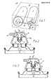
- the apparatus comprises a high volume/low pressure source of gas, e.g. a vessel in the form of an aerosol can 1 containing carbon dioxide under pressure; a standard aerosol can valve 2; a container in the form of a bottle 3 which is made e.g. of polyethyleneterephthalate (PET) and contains the liquid to be aerated (viz.
- a high volume/low pressure source of gas e.g. a vessel in the form of an aerosol can 1 containing carbon dioxide under pressure
- a standard aerosol can valve 2 e.g. of polyethyleneterephthalate (PET) and contains the liquid to be aerated (viz.
- PET polyethyleneterephthalate
- the beverage to be carbonated and which is connected to the can 1 via the valve 2, a conduit 14 and a pressure regulator 4, which is capable of delivering the carbon dioxide to the bottle 3 at a reduced pressure (about 0.1 MPa) substantially lower than the source pressure (about 1 MPa) under which the carbon dioxide is kept in the can 1; and flow control means in the form of a 3-way tap 5, which permits delivery of the carbon dioxide to, and dispensing of the carbonated beverage from, the bottle 3, as hereinbefore described.
- the aforesaid integers 1-5 are packed into an enclosure in the form of a cardboard outer box 6.
- the regulator 4 comprises a housing 7 defining a "button" which, when depressed in the direction of the arrow A, converts the apparatus from an "in transit” to an "in use” condition.
- the housing 7 has a skirt portion 7a and an outlet 8 for the carbon dioxide from the can 1 into the bottle 3.
- the housing 7 sits on a curl 9 on a cup 10 in which the valve 2 is mounted.
- the regulator 4 further comprises a needle valve 11 which cooperates with a valve seat 12, and a resilient diaphragm 13; the latter is so dimensioned that the required pressure acting on its downstream area overcomes its initial set away from the valve seat, thus closing off the gas supply. Gas is then supplied to said container at a substantially constant pressure.
- the 3-way tap 5 shown is screwed on to the neck of the bottle 3 by rotation about the latter's longitudinal axis along which a dip tube 15 extends into the bottle 3.
- the tap 5 has an inlet 16 for the carbon dioxide and a gasket 17 of flowed-in lining compound seals the tap 5 to the bottle 3.
- the conduit 14 (Fig. 1) interconnects the outlet 8 of the regulator 4 with the inlet of the tap 5.
- the tap 5 In its three angular positions with respect to the bottle 3, the tap 5 respectively (1) closes the bottle 3 for transit; (2) communicates with the can 1 so as to receive the carbon dioxide therefrom under pressure when the can 1 has been actuated by the regulator 4 being in the position shown in Figure 3 (as will be hereinafter described); and (3) puts the bottle 3 into communication with atmosphere (viz. for dispensing the beverage therefrom) through the dip tube 15 and a spout 18).
- the tap 5 shown in Figure 5 has a body portion provided with a tapered hole into which fits a similarly tapered plug 19 shown in cross-section in Fig. 4.
- the main working part of all the plugs 19 shown in Figs. 5 to 7 is the same. It is partly hollow (as shown in Fig. 7) and provided with an arcuate surface channel 20 for the carbon dioxide and a hole 21 communicating with the beverage in the bottle 3 via the dip tube 15, and with the spout 18 via a hollow in the plug 19.
- the plug 19 according to Fig. 5 has a handle 22 having a boss 23 of square cross-section is arranged to mate with a corresponding square-section recess 24 in the end of the plug 19, for manually rotating the plug for selective communication as described with reference to the tap shown in Figure 4 (whose handle is not shown).
- the plug 19 shown in Figure 6 differs from that shown in Figure 5 only in that the handle 22, instead of being detachable from the plug 19, is moulded integrally therewith.
- the plug 19 shown in Figure 7 has a "spike" handle 25 for insertion in transverse holes 26 in a boss 27 extending axially from the plug 19.
- the channel 20 for the carbon dioxide is provided in a relatively thick region of the moulded plug 19 so as to have a relatively small effect on the rigidity of the latter, whilst the hole 21 for the beverage is provided in a thinner region of the tapered plug 19, this being tolerable because the quality of sealing for the liquid beverage is less critical than that for the pressurized carbon dioxide gas.
- the consumer opens a prepared panel (not shown) in the cardboard outer box 6. This reveals a further card panel (not snown), projecting through which is the tap 5 and a large diameter plastics button defined by the top of the housing 7.
- Depressing this button locks open the aerosol valve 2 by resiliently snapping the skirt portion 7a of the housing 7 over, so as to engage, the curl 9 on the cup 10 (see Figures 2 and 3).
- Carbon dioxide passes at a so controlled pressure into the bottle 3 as required to maintain the required internal pressure. Opening of the tap 5 to dispense beverage reduces the pressure in the bottle 3 but the regulator 4 makes it up to the desired "keeping pressure”.
- the size of the can 1 and the characteristics of the diaphragm 13 are tailored to suit the particular carbonation requirements for specific beverages.
- the main advantage of the apparatus embodying the invention is its construction which enables the apparatus to be produced cheaply enough for it to be disposable after use. Because the known apparatus uses a high-pressure bulb as a source of gas, the means for the attachment and bursting of the bulb and the associated regulator must use engineered parts of metal so that they are very expensive (about £5.00). In contrast, an apparatus according to the invention uses a low-pressure source of gas. It uses no bursting means and the regulator is, as shown, made of plastics mouldings which snap fit together during assembly, so that its cost is so low (about £0.05) that the whole apparatus is disposable. This brings about the advantage that the user need not fit the source of gas and clean the regulator. A further advantage is that the provision of a package which is safe in transit because the gas is in a can sealed by a valve and the bottle of liquid id firmly closed.
Abstract
Description
- This invention relates to apparatus for storing and dispensing a quantity of aerated liquid. The apparatus is especially intended, though not exclusively suitable, for the storage and dispensing of so-called "carbonated beverages". By the term "carbonated beverages" is meant beverages which are colloquially usually referred to as "fizzy drinks", viz. lemonade, beers and other beverages which are made "fizzy" by the introduction of a gas. The gas most frequently used for this purpose is carbon dioxide. Likewise the term "aerated liquid" as used herein connotes a liquid which has been made "fizzy" by the introduction of any such gas as aforesaid.
- The present invention may, for example, find application where, in order to avoid deterioration during storage owing to its chemical reaction with its environmental atmosphere, a liquid must be maintained in contact with a particular gas under a predetermined substantially constant pressure. However, the main field of application of the invention is presently thought to be that of such carbonated beverages as aforesaid; for convenience therefore, but without prejudice to the generality of the scope of the invention as hereinbefore stated and as hereinafter defined in the claims, the invention will hereinafter be discussed and exemplified in the context of such beverages.
- Apparatus presently available for storing and dispensing a carbonated beverage includes the well-known beer can tap, which has a regulator but which uses a low volume/high-pressure source in the form of high-pressure bulbs containing carbon dioxide (at a pressure of about 7 MPa) which have no valve - only a bursting disc - and where once use has started there is no way to shut off the Pas supply.
- There has also previously been proposed a liquid or powder spray, the subject of British patent ?22 347. The complete specification of that patent discloses such a sprayer having separate containers for a product and a propellant joined so that pressure on a joint handle releases the propellant into the product container and then the exit valve opens and the product can discharge. The disclosure includes a mechanical coupling of the delivery valve to a gas supply valve, but does not propose any automatic pressure regulating means.
- It is an object of the present invention to provide apparatus which, unlike the prior art apparatus hereinbefore outlined, enables the storage and dispensing of an aerated liquid product over a period of time, e.g. fizzy drinks glass by glass, without deterioration of the product, viz. without progressive loss of "fizz" or "sparkle".
- For this purpose, in accordance with the present invention, apparatus for storing and dispensing a quantity of aerated liquid in which the extent of aeration is maintained as said quantity is progressively dispensed, comprises a low-pressure source of gas in the form of a vessel; a valve closing said vessel; a container for said liquid, said container being connected to said vessel via a plastics pressure regulator, which is capable of delivering said gas to said container at a pressure substantially lower than said pressure under which said gas is kept in said vessel; and flow control means which permit delivery of said gas to, and dispensing of said liquid from, said container.
- One form of apparatus embodying the invention, viz. a said apparatus for maintaining the carbonation of a beverage in a container, will now be described, by way of example, with reference to the accompanying diagrammatic drawings, in which:-
- Figure 1 is a perspective general assembly drawing of the apparatus;
- Figures 2 and 3 are sectional elevations of the regulator showing the latter respectively when the apparatus is in transit and when it is in use;
- Figure 4 is a sectional elevation of the flow control means, in the form of a 3-way tap;
- Figures 5 and 6 are perspective views of alternative flow control means; and
- Figure 7 is a sectional elevation of a modified form of the flow control means shown in Figures 5 and 6.
- Referring now to Figures 1 to 3, the apparatus comprises a high volume/low pressure source of gas, e.g. a vessel in the form of an aerosol can 1 containing carbon dioxide under pressure; a standard aerosol can
valve 2; a container in the form of abottle 3 which is made e.g. of polyethyleneterephthalate (PET) and contains the liquid to be aerated (viz. the beverage to be carbonated) and which is connected to thecan 1 via thevalve 2, aconduit 14 and a pressure regulator 4, which is capable of delivering the carbon dioxide to thebottle 3 at a reduced pressure (about 0.1 MPa) substantially lower than the source pressure (about 1 MPa) under which the carbon dioxide is kept in thecan 1; and flow control means in the form of a 3-way tap 5, which permits delivery of the carbon dioxide to, and dispensing of the carbonated beverage from, thebottle 3, as hereinbefore described. - The aforesaid integers 1-5 are packed into an enclosure in the form of a cardboard
outer box 6. - The regulator 4 comprises a housing 7 defining a "button" which, when depressed in the direction of the arrow A, converts the apparatus from an "in transit" to an "in use" condition.
- The housing 7 has a
skirt portion 7a and an outlet 8 for the carbon dioxide from thecan 1 into thebottle 3. In the "in transit" condition (Figure 2) the housing 7 sits on acurl 9 on acup 10 in which thevalve 2 is mounted. - The regulator 4 further comprises a
needle valve 11 which cooperates with avalve seat 12, and aresilient diaphragm 13; the latter is so dimensioned that the required pressure acting on its downstream area overcomes its initial set away from the valve seat, thus closing off the gas supply. Gas is then supplied to said container at a substantially constant pressure. - Referring now to Figure 4, the 3-
way tap 5 shown is screwed on to the neck of thebottle 3 by rotation about the latter's longitudinal axis along which adip tube 15 extends into thebottle 3. - The
tap 5 has aninlet 16 for the carbon dioxide and agasket 17 of flowed-in lining compound seals thetap 5 to thebottle 3. The conduit 14 (Fig. 1) interconnects the outlet 8 of the regulator 4 with the inlet of thetap 5. - In its three angular positions with respect to the
bottle 3, thetap 5 respectively (1) closes thebottle 3 for transit; (2) communicates with thecan 1 so as to receive the carbon dioxide therefrom under pressure when thecan 1 has been actuated by the regulator 4 being in the position shown in Figure 3 (as will be hereinafter described); and (3) puts thebottle 3 into communication with atmosphere (viz. for dispensing the beverage therefrom) through thedip tube 15 and a spout 18). - The
tap 5 shown in Figure 5 has a body portion provided with a tapered hole into which fits a similarlytapered plug 19 shown in cross-section in Fig. 4. The main working part of all theplugs 19 shown in Figs. 5 to 7 is the same. It is partly hollow (as shown in Fig. 7) and provided with anarcuate surface channel 20 for the carbon dioxide and ahole 21 communicating with the beverage in thebottle 3 via thedip tube 15, and with thespout 18 via a hollow in theplug 19. - The
plug 19 according to Fig. 5 has ahandle 22 having aboss 23 of square cross-section is arranged to mate with a corresponding square-section recess 24 in the end of theplug 19, for manually rotating the plug for selective communication as described with reference to the tap shown in Figure 4 (whose handle is not shown). - The
plug 19 shown in Figure 6 differs from that shown in Figure 5 only in that thehandle 22, instead of being detachable from theplug 19, is moulded integrally therewith. - The
plug 19 shown in Figure 7 has a "spike"handle 25 for insertion intransverse holes 26 in aboss 27 extending axially from theplug 19. It will also be noted that thechannel 20 for the carbon dioxide is provided in a relatively thick region of themoulded plug 19 so as to have a relatively small effect on the rigidity of the latter, whilst thehole 21 for the beverage is provided in a thinner region of thetapered plug 19, this being tolerable because the quality of sealing for the liquid beverage is less critical than that for the pressurized carbon dioxide gas. - In use, the consumer opens a prepared panel (not shown) in the cardboard
outer box 6. This reveals a further card panel (not snown), projecting through which is thetap 5 and a large diameter plastics button defined by the top of the housing 7. - Depressing this button locks open the
aerosol valve 2 by resiliently snapping theskirt portion 7a of the housing 7 over, so as to engage, thecurl 9 on the cup 10 (see Figures 2 and 3). - Carbon dioxide passes at a so controlled pressure into the
bottle 3 as required to maintain the required internal pressure. Opening of thetap 5 to dispense beverage reduces the pressure in thebottle 3 but the regulator 4 makes it up to the desired "keeping pressure". - The size of the
can 1 and the characteristics of thediaphragm 13 are tailored to suit the particular carbonation requirements for specific beverages. - The main advantage of the apparatus embodying the invention is its construction which enables the apparatus to be produced cheaply enough for it to be disposable after use. Because the known apparatus uses a high-pressure bulb as a source of gas, the means for the attachment and bursting of the bulb and the associated regulator must use engineered parts of metal so that they are very expensive (about £15.00). In contrast, an apparatus according to the invention uses a low-pressure source of gas. It uses no bursting means and the regulator is, as shown, made of plastics mouldings which snap fit together during assembly, so that its cost is so low (about £0.05) that the whole apparatus is disposable. This brings about the advantage that the user need not fit the source of gas and clean the regulator. A further advantage is that the provision of a package which is safe in transit because the gas is in a can sealed by a valve and the bottle of liquid id firmly closed.
Claims (5)
Priority Applications (1)
| Application Number | Priority Date | Filing Date | Title |
|---|---|---|---|
| AT86307262T ATE58357T1 (en) | 1985-09-24 | 1986-09-22 | STORAGE AND DELIVERY DEVICE FOR AERATED LIQUIDS. |
Applications Claiming Priority (2)
| Application Number | Priority Date | Filing Date | Title |
|---|---|---|---|
| GB8523575 | 1985-09-24 | ||
| GB08523575A GB2185537A (en) | 1985-09-24 | 1985-09-24 | Aerated liquid storage/dispensing apparatus |
Publications (3)
| Publication Number | Publication Date |
|---|---|
| EP0217615A2 true EP0217615A2 (en) | 1987-04-08 |
| EP0217615A3 EP0217615A3 (en) | 1988-02-17 |
| EP0217615B1 EP0217615B1 (en) | 1990-11-14 |
Family
ID=10585659
Family Applications (1)
| Application Number | Title | Priority Date | Filing Date |
|---|---|---|---|
| EP86307262A Expired - Lifetime EP0217615B1 (en) | 1985-09-24 | 1986-09-22 | Aerated liquid storage/dispensing apparatus |
Country Status (11)
| Country | Link |
|---|---|
| US (2) | US4785977A (en) |
| EP (1) | EP0217615B1 (en) |
| JP (1) | JPS62122988A (en) |
| AT (1) | ATE58357T1 (en) |
| CA (1) | CA1275982C (en) |
| DE (1) | DE3675620D1 (en) |
| DK (1) | DK164042C (en) |
| ES (1) | ES2002192A6 (en) |
| GB (2) | GB2185537A (en) |
| IE (1) | IE59384B1 (en) |
| ZA (1) | ZA867226B (en) |
Cited By (5)
| Publication number | Priority date | Publication date | Assignee | Title |
|---|---|---|---|---|
| EP0299767A1 (en) * | 1987-07-14 | 1989-01-18 | The Coca-Cola Company | Premix dispensing system |
| US4804116A (en) * | 1986-09-11 | 1989-02-14 | Metal Box Public Limited Company | Valve for dispensing fluid from a container |
| EP0342977A1 (en) * | 1988-05-18 | 1989-11-23 | Sca Packaging Limited | Dispensing valve |
| EP0342978A1 (en) * | 1988-05-18 | 1989-11-23 | Sca Packaging Limited | Dispensers for gasified beverages |
| WO1999011562A1 (en) * | 1997-09-01 | 1999-03-11 | Sapporo Breweries Ltd. | Method and apparatus of dispensing carbonated drink which prevents excessive supply of carbon dioxide gas |
Families Citing this family (21)
| Publication number | Priority date | Publication date | Assignee | Title |
|---|---|---|---|---|
| GB2185537A (en) * | 1985-09-24 | 1987-07-22 | Metal Box Plc | Aerated liquid storage/dispensing apparatus |
| IN174351B (en) * | 1988-03-08 | 1994-11-12 | British Tech Group | |
| US5108337A (en) * | 1990-11-05 | 1992-04-28 | Sloan John D | Inflatable balloon system |
| US5635232A (en) * | 1994-11-23 | 1997-06-03 | Perlage Systems, Inc. | Safe method and apparatus for preserving and re-carbonating beverages |
| NL1009292C1 (en) | 1998-05-29 | 1999-11-30 | Packaging Tech Holding Sa | Pressure control device for maintaining a constant predetermined pressure in a container. |
| NL1012754C2 (en) * | 1999-07-30 | 2001-02-01 | Presstech N V | Pressure control device. |
| DE10222750C1 (en) * | 2002-05-23 | 2003-11-06 | Walter Schmidt | Carbon monoxide inhalation device for testing blood volume and haemoglobin has device for controlled opening of carbon monoxide container positioned between oxygen bag and mouthpiece |
| AU2002353492A1 (en) * | 2002-10-15 | 2004-05-04 | Claudio Ferrari | Device for preserving the gas content of carbonated drinks even as they are being poured out |
| NL1022456C2 (en) * | 2003-01-21 | 2004-07-22 | Packaging Tech Holding Sa | Pressure package system for applying a working pressure to a fluid contained in a pressure package. |
| NL1022455C2 (en) * | 2003-01-21 | 2004-07-22 | Packaging Tech Holding Sa | System for applying a working pressure to a content of a pressure package with the aid of a propellant. |
| FR2899210A1 (en) * | 2006-03-30 | 2007-10-05 | Ad Venta Sarl | Pneumatic component for micro-diffusion of e.g. perfume, has fixation system forming intermediate chamber between piston and upper part of container, where body has orifice communicating with chamber when body is fixed on container |
| US20080217363A1 (en) * | 2007-03-09 | 2008-09-11 | Vitantonio Marc L | Beverage dispensing assembly |
| US20090140006A1 (en) * | 2007-03-09 | 2009-06-04 | Vitantonio Marc L | Beverage dispensing assembly |
| US8070023B2 (en) * | 2007-03-09 | 2011-12-06 | On Tap Llc | Beverage dispensing assembly |
| US20080217362A1 (en) * | 2007-03-09 | 2008-09-11 | On Tap Llc | Beverage dispensing assembly |
| US20090321443A1 (en) * | 2007-03-09 | 2009-12-31 | Taggart Jeffrey S | Method for filling a vessel with a gas entrained beverage and a consumable consumer product including the beverage |
| US20090302038A1 (en) * | 2007-03-09 | 2009-12-10 | Taggart Jeffrey S | Beverage Dispensing Assembly |
| US20100108556A1 (en) * | 2008-10-30 | 2010-05-06 | Joseph Claffy | Storage container |
| IT1394818B1 (en) * | 2009-07-10 | 2012-07-13 | Drechsel | THROUGH-FLOW PRESSURE REGULATOR DEVICE FOR IRRIGATION SYSTEMS |
| IT1400344B1 (en) * | 2010-05-07 | 2013-05-24 | Drechsel | PRESSURE REGULATOR FOR IRRIGATION SYSTEMS |
| US9803163B2 (en) * | 2012-04-05 | 2017-10-31 | Anheuser-Busch Llc | Systems for carbonating customized beverages |
Citations (6)
| Publication number | Priority date | Publication date | Assignee | Title |
|---|---|---|---|---|
| NL290697A (en) * | 1900-01-01 | |||
| GB922347A (en) * | 1958-11-21 | 1963-03-27 | Union Carbide Corp | Improvements in and relating to spraying |
| GB1177288A (en) * | 1966-05-27 | 1970-01-07 | Nat Distillers Chem Corp | Carbonated Beverage Dispenser for Removable Attachment to a Beverage Container |
| US3843027A (en) * | 1971-12-29 | 1974-10-22 | Reynolds Metals Co | Fluid dispensing container construction |
| CH613912A5 (en) * | 1974-03-05 | 1979-10-31 | Zieh Press Und Stanzwerk Zwint | Actuation closure for containers of liquids subjected to compressed gas |
| EP0026077A1 (en) * | 1979-09-21 | 1981-04-01 | Clearline Home & Leisure Products Limited | Gas injection apparatus |
Family Cites Families (21)
| Publication number | Priority date | Publication date | Assignee | Title |
|---|---|---|---|---|
| US973609A (en) * | 1910-04-25 | 1910-10-25 | John A Abrams | Pressure-regulating valve for gas-burners. |
| US1072239A (en) * | 1912-05-25 | 1913-09-02 | Arthur Kleinfeldt | Siphon for dispensing liquids. |
| DE645987C (en) * | 1935-10-18 | 1937-06-10 | Fried Krupp Akt Ges | Self-donor |
| US2571433A (en) * | 1948-03-23 | 1951-10-16 | Joseph L Fine | Beverage dispensing receptacle |
| US3240403A (en) * | 1960-04-28 | 1966-03-15 | Modern Lab Inc | Pressurized dispensing device |
| GB938528A (en) * | 1961-06-26 | 1963-10-02 | Guinness Son & Co Ltd A | Connecting head for use with casks, and like receptacles containing liquid under pressure |
| US3161327A (en) * | 1962-02-15 | 1964-12-15 | Wilhelm Schmidding | Siphon dispenser |
| US3186599A (en) * | 1963-10-15 | 1965-06-01 | Evelyn S Levinson | Dispenser for liquid in upright container with controlled atmosphere |
| US3259194A (en) * | 1964-04-20 | 1966-07-05 | Stoppafire Ltd | Light-weight portable fire extinguishers |
| GB1135971A (en) * | 1965-02-12 | 1968-12-11 | British Oxygen Co Ltd | Valve assembly and mechanism for dispensing liquids by gaseous pressure |
| US3327899A (en) * | 1965-09-13 | 1967-06-27 | Conax Corp | Beverage dispensing apparatus |
| GB1196965A (en) * | 1967-09-19 | 1970-07-01 | Nat Can Corp | Attachment for Supplying Gas Pressure to and Dispensing a Product from a Disposable Container |
| GB1236645A (en) * | 1968-04-30 | 1971-06-23 | Euracom Sa | Apparatus for dispensing gas-charged liquids |
| US3613954A (en) * | 1968-06-20 | 1971-10-19 | Schlitz Brewing Co J | Dispensing apparatus |
| FR2045204A6 (en) * | 1969-06-19 | 1971-02-26 | Giroud Henri | |
| US3756472A (en) * | 1971-10-18 | 1973-09-04 | Hohnsom & Son Inc S | Micro-emitter |
| GB1422334A (en) * | 1972-03-21 | 1976-01-28 | ||
| BE826799R (en) * | 1974-03-25 | 1975-07-16 | BEER TAP DEVICE | |
| US3930519A (en) * | 1975-02-13 | 1976-01-06 | The United States Of America As Represented By The Secretary Of The Army | Pressure regulator |
| JPS6221593Y2 (en) * | 1981-06-05 | 1987-06-01 | ||
| GB2185537A (en) * | 1985-09-24 | 1987-07-22 | Metal Box Plc | Aerated liquid storage/dispensing apparatus |
-
1985
- 1985-09-24 GB GB08523575A patent/GB2185537A/en not_active Withdrawn
-
1986
- 1986-09-12 DK DK439386A patent/DK164042C/en not_active IP Right Cessation
- 1986-09-16 GB GB8622256A patent/GB2180890B/en not_active Expired
- 1986-09-18 US US06/908,992 patent/US4785977A/en not_active Expired - Fee Related
- 1986-09-22 EP EP86307262A patent/EP0217615B1/en not_active Expired - Lifetime
- 1986-09-22 DE DE8686307262T patent/DE3675620D1/en not_active Expired - Lifetime
- 1986-09-22 AT AT86307262T patent/ATE58357T1/en not_active IP Right Cessation
- 1986-09-23 ZA ZA867226A patent/ZA867226B/en unknown
- 1986-09-23 CA CA000518794A patent/CA1275982C/en not_active Expired - Lifetime
- 1986-09-23 IE IE251686A patent/IE59384B1/en not_active IP Right Cessation
- 1986-09-24 ES ES8602135A patent/ES2002192A6/en not_active Expired
- 1986-09-24 JP JP61223928A patent/JPS62122988A/en active Granted
-
1988
- 1988-05-26 US US07/199,290 patent/US4940169A/en not_active Expired - Fee Related
Patent Citations (6)
| Publication number | Priority date | Publication date | Assignee | Title |
|---|---|---|---|---|
| NL290697A (en) * | 1900-01-01 | |||
| GB922347A (en) * | 1958-11-21 | 1963-03-27 | Union Carbide Corp | Improvements in and relating to spraying |
| GB1177288A (en) * | 1966-05-27 | 1970-01-07 | Nat Distillers Chem Corp | Carbonated Beverage Dispenser for Removable Attachment to a Beverage Container |
| US3843027A (en) * | 1971-12-29 | 1974-10-22 | Reynolds Metals Co | Fluid dispensing container construction |
| CH613912A5 (en) * | 1974-03-05 | 1979-10-31 | Zieh Press Und Stanzwerk Zwint | Actuation closure for containers of liquids subjected to compressed gas |
| EP0026077A1 (en) * | 1979-09-21 | 1981-04-01 | Clearline Home & Leisure Products Limited | Gas injection apparatus |
Cited By (9)
| Publication number | Priority date | Publication date | Assignee | Title |
|---|---|---|---|---|
| US4804116A (en) * | 1986-09-11 | 1989-02-14 | Metal Box Public Limited Company | Valve for dispensing fluid from a container |
| EP0299767A1 (en) * | 1987-07-14 | 1989-01-18 | The Coca-Cola Company | Premix dispensing system |
| EP0342977A1 (en) * | 1988-05-18 | 1989-11-23 | Sca Packaging Limited | Dispensing valve |
| EP0342978A1 (en) * | 1988-05-18 | 1989-11-23 | Sca Packaging Limited | Dispensers for gasified beverages |
| US5014886A (en) * | 1988-05-18 | 1991-05-14 | Reed Packaging Limited | Dispensing valve |
| AU618354B2 (en) * | 1988-05-18 | 1991-12-19 | Reed Packaging Limited | Dispensers for gasified beverages |
| US5111974A (en) * | 1988-05-18 | 1992-05-12 | Reed Pakaging Limited | Dispensers for gasified beverages |
| AU627457B2 (en) * | 1988-05-18 | 1992-08-27 | Reed Packaging Limited | Dispensing valve |
| WO1999011562A1 (en) * | 1997-09-01 | 1999-03-11 | Sapporo Breweries Ltd. | Method and apparatus of dispensing carbonated drink which prevents excessive supply of carbon dioxide gas |
Also Published As
| Publication number | Publication date |
|---|---|
| GB2180890B (en) | 1989-11-15 |
| IE59384B1 (en) | 1994-02-23 |
| ZA867226B (en) | 1987-05-27 |
| CA1275982C (en) | 1990-11-06 |
| EP0217615B1 (en) | 1990-11-14 |
| GB2180890A (en) | 1987-04-08 |
| DK439386D0 (en) | 1986-09-12 |
| DK164042C (en) | 1992-09-28 |
| ES2002192A6 (en) | 1988-07-16 |
| GB8523575D0 (en) | 1985-10-30 |
| GB2185537A (en) | 1987-07-22 |
| IE862516L (en) | 1987-03-24 |
| US4940169A (en) | 1990-07-10 |
| EP0217615A3 (en) | 1988-02-17 |
| JPH032755B2 (en) | 1991-01-16 |
| DK164042B (en) | 1992-05-04 |
| GB8622256D0 (en) | 1986-10-22 |
| DK439386A (en) | 1987-03-25 |
| ATE58357T1 (en) | 1990-11-15 |
| DE3675620D1 (en) | 1990-12-20 |
| US4785977A (en) | 1988-11-22 |
| JPS62122988A (en) | 1987-06-04 |
Similar Documents
| Publication | Publication Date | Title |
|---|---|---|
| EP0217615A2 (en) | Aerated liquid storage/dispensing apparatus | |
| US5443186A (en) | Fluid dispenser which has a button actuated regulator valve and a pressure relief port in the button | |
| US8251257B2 (en) | Vessel having CO2 compressed gas source | |
| US5180081A (en) | Pouring spout and carbonation retention apparatus | |
| US5329975A (en) | Apparatus for pressurizing containers and carbonating liquids | |
| US8763866B2 (en) | Vessel having compressed CO2 gas source | |
| US4867209A (en) | Portable hand holdable carbonating apparatus | |
| US5139179A (en) | Apparatus for dispensing and preserving liquids | |
| US10160560B2 (en) | Carbonation preservation device | |
| US5040703A (en) | Bottle closure system with repressurization and dispensing means | |
| US20110147406A1 (en) | Two piece dispenser | |
| US4871096A (en) | Liquid dispenser for a bottle | |
| US4804116A (en) | Valve for dispensing fluid from a container | |
| EP0328598A1 (en) | Improved beverage dispenser | |
| AU2006254390A1 (en) | Vessel having pressurized CO2 gas source | |
| EP0420561A1 (en) | Container for dispensing carbonated liquids | |
| US6079458A (en) | Carbon acid dispenser | |
| JP2002337991A (en) | Beverage discharging device | |
| EP0281607A4 (en) | Liquid dispenser. | |
| WO2000024650A1 (en) | Beverage container for a carbonated beverage | |
| Oberhofer et al. | Vessel having CO 2 compressed gas source | |
| RO118710B1 (en) | Closing device for discharging pressurized liquids from containers | |
| AU2120088A (en) | Improved beverage dispenser |
Legal Events
| Date | Code | Title | Description |
|---|---|---|---|
| PUAI | Public reference made under article 153(3) epc to a published international application that has entered the european phase |
Free format text: ORIGINAL CODE: 0009012 |
|
| 17P | Request for examination filed |
Effective date: 19860929 |
|
| AK | Designated contracting states |
Kind code of ref document: A2 Designated state(s): AT BE CH DE FR IT LI LU NL SE |
|
| PUAL | Search report despatched |
Free format text: ORIGINAL CODE: 0009013 |
|
| AK | Designated contracting states |
Kind code of ref document: A3 Designated state(s): AT BE CH DE FR IT LI LU NL SE |
|
| 17Q | First examination report despatched |
Effective date: 19890227 |
|
| RAP1 | Party data changed (applicant data changed or rights of an application transferred) |
Owner name: MB GROUP PLC |
|
| RAP1 | Party data changed (applicant data changed or rights of an application transferred) |
Owner name: CMB PACKAGING (UK) LIMITED |
|
| RAP1 | Party data changed (applicant data changed or rights of an application transferred) |
Owner name: CMB FOODCAN PLC |
|
| GRAA | (expected) grant |
Free format text: ORIGINAL CODE: 0009210 |
|
| AK | Designated contracting states |
Kind code of ref document: B1 Designated state(s): AT BE CH DE FR IT LI LU NL SE |
|
| REF | Corresponds to: |
Ref document number: 58357 Country of ref document: AT Date of ref document: 19901115 Kind code of ref document: T |
|
| REF | Corresponds to: |
Ref document number: 3675620 Country of ref document: DE Date of ref document: 19901220 |
|
| ET | Fr: translation filed | ||
| ITF | It: translation for a ep patent filed |
Owner name: STUDIO TORTA SOCIETA' SEMPLICE |
|
| PLBE | No opposition filed within time limit |
Free format text: ORIGINAL CODE: 0009261 |
|
| STAA | Information on the status of an ep patent application or granted ep patent |
Free format text: STATUS: NO OPPOSITION FILED WITHIN TIME LIMIT |
|
| 26N | No opposition filed | ||
| ITTA | It: last paid annual fee | ||
| EPTA | Lu: last paid annual fee | ||
| EAL | Se: european patent in force in sweden |
Ref document number: 86307262.5 |
|
| PGFP | Annual fee paid to national office [announced via postgrant information from national office to epo] |
Ref country code: LU Payment date: 19950801 Year of fee payment: 10 |
|
| PGFP | Annual fee paid to national office [announced via postgrant information from national office to epo] |
Ref country code: FR Payment date: 19950803 Year of fee payment: 10 |
|
| PGFP | Annual fee paid to national office [announced via postgrant information from national office to epo] |
Ref country code: SE Payment date: 19950814 Year of fee payment: 10 Ref country code: CH Payment date: 19950814 Year of fee payment: 10 Ref country code: AT Payment date: 19950814 Year of fee payment: 10 |
|
| PGFP | Annual fee paid to national office [announced via postgrant information from national office to epo] |
Ref country code: NL Payment date: 19950817 Year of fee payment: 10 |
|
| PGFP | Annual fee paid to national office [announced via postgrant information from national office to epo] |
Ref country code: DE Payment date: 19950823 Year of fee payment: 10 |
|
| PGFP | Annual fee paid to national office [announced via postgrant information from national office to epo] |
Ref country code: BE Payment date: 19950824 Year of fee payment: 10 |
|
| PG25 | Lapsed in a contracting state [announced via postgrant information from national office to epo] |
Ref country code: LU Free format text: LAPSE BECAUSE OF NON-PAYMENT OF DUE FEES Effective date: 19960922 Ref country code: AT Effective date: 19960922 |
|
| PG25 | Lapsed in a contracting state [announced via postgrant information from national office to epo] |
Ref country code: SE Effective date: 19960923 |
|
| PG25 | Lapsed in a contracting state [announced via postgrant information from national office to epo] |
Ref country code: LI Effective date: 19960930 Ref country code: FR Effective date: 19960930 Ref country code: CH Effective date: 19960930 Ref country code: BE Effective date: 19960930 |
|
| BERE | Be: lapsed |
Owner name: CMB FOODCAN P.L.C. Effective date: 19960930 |
|
| PG25 | Lapsed in a contracting state [announced via postgrant information from national office to epo] |
Ref country code: NL Effective date: 19970401 |
|
| REG | Reference to a national code |
Ref country code: CH Ref legal event code: PL |
|
| NLV4 | Nl: lapsed or anulled due to non-payment of the annual fee |
Effective date: 19970401 |
|
| PG25 | Lapsed in a contracting state [announced via postgrant information from national office to epo] |
Ref country code: DE Effective date: 19970603 |
|
| EUG | Se: european patent has lapsed |
Ref document number: 86307262.5 |
|
| REG | Reference to a national code |
Ref country code: FR Ref legal event code: ST |
|
| REG | Reference to a national code |
Ref country code: FR Ref legal event code: ST |
|
| PG25 | Lapsed in a contracting state [announced via postgrant information from national office to epo] |
Ref country code: IT Free format text: LAPSE BECAUSE OF NON-PAYMENT OF DUE FEES;WARNING: LAPSES OF ITALIAN PATENTS WITH EFFECTIVE DATE BEFORE 2007 MAY HAVE OCCURRED AT ANY TIME BEFORE 2007. THE CORRECT EFFECTIVE DATE MAY BE DIFFERENT FROM THE ONE RECORDED. Effective date: 20050922 |