EP0219334A2 - Cavity transfer mixing extruder - Google Patents
Cavity transfer mixing extruder Download PDFInfo
- Publication number
- EP0219334A2 EP0219334A2 EP86307883A EP86307883A EP0219334A2 EP 0219334 A2 EP0219334 A2 EP 0219334A2 EP 86307883 A EP86307883 A EP 86307883A EP 86307883 A EP86307883 A EP 86307883A EP 0219334 A2 EP0219334 A2 EP 0219334A2
- Authority
- EP
- European Patent Office
- Prior art keywords
- cavity
- cavities
- rotor
- stator
- rows
- Prior art date
- Legal status (The legal status is an assumption and is not a legal conclusion. Google has not performed a legal analysis and makes no representation as to the accuracy of the status listed.)
- Granted
Links
- 238000001125 extrusion Methods 0.000 claims abstract description 36
- 239000000463 material Substances 0.000 abstract description 61
- 229920001971 elastomer Polymers 0.000 description 22
- 239000005060 rubber Substances 0.000 description 22
- 150000001875 compounds Chemical class 0.000 description 18
- 239000004033 plastic Substances 0.000 description 7
- 229920003023 plastic Polymers 0.000 description 7
- 239000011346 highly viscous material Substances 0.000 description 6
- 244000043261 Hevea brasiliensis Species 0.000 description 3
- 239000012530 fluid Substances 0.000 description 3
- 230000020169 heat generation Effects 0.000 description 3
- 238000002844 melting Methods 0.000 description 3
- 230000008018 melting Effects 0.000 description 3
- 229920003052 natural elastomer Polymers 0.000 description 3
- 229920001194 natural rubber Polymers 0.000 description 3
- 238000010008 shearing Methods 0.000 description 3
- 239000000126 substance Substances 0.000 description 3
- 101000738911 Homo sapiens Mismatch repair endonuclease PMS2 Proteins 0.000 description 1
- 102100037480 Mismatch repair endonuclease PMS2 Human genes 0.000 description 1
- 230000001419 dependent effect Effects 0.000 description 1
- 238000007599 discharging Methods 0.000 description 1
Images


Classifications
-
- B—PERFORMING OPERATIONS; TRANSPORTING
- B29—WORKING OF PLASTICS; WORKING OF SUBSTANCES IN A PLASTIC STATE IN GENERAL
- B29C—SHAPING OR JOINING OF PLASTICS; SHAPING OF MATERIAL IN A PLASTIC STATE, NOT OTHERWISE PROVIDED FOR; AFTER-TREATMENT OF THE SHAPED PRODUCTS, e.g. REPAIRING
- B29C48/00—Extrusion moulding, i.e. expressing the moulding material through a die or nozzle which imparts the desired form; Apparatus therefor
- B29C48/25—Component parts, details or accessories; Auxiliary operations
- B29C48/36—Means for plasticising or homogenising the moulding material or forcing it through the nozzle or die
- B29C48/50—Details of extruders
- B29C48/505—Screws
- B29C48/56—Screws having grooves or cavities other than the thread or the channel
-
- B—PERFORMING OPERATIONS; TRANSPORTING
- B29—WORKING OF PLASTICS; WORKING OF SUBSTANCES IN A PLASTIC STATE IN GENERAL
- B29C—SHAPING OR JOINING OF PLASTICS; SHAPING OF MATERIAL IN A PLASTIC STATE, NOT OTHERWISE PROVIDED FOR; AFTER-TREATMENT OF THE SHAPED PRODUCTS, e.g. REPAIRING
- B29C48/00—Extrusion moulding, i.e. expressing the moulding material through a die or nozzle which imparts the desired form; Apparatus therefor
- B29C48/25—Component parts, details or accessories; Auxiliary operations
- B29C48/36—Means for plasticising or homogenising the moulding material or forcing it through the nozzle or die
- B29C48/465—Means for plasticising or homogenising the moulding material or forcing it through the nozzle or die using rollers
- B29C48/467—Means for plasticising or homogenising the moulding material or forcing it through the nozzle or die using rollers using single rollers, e.g. provided with protrusions, closely surrounded by a housing with movement of the material in the axial direction
- B29C48/468—Cavity transfer mixing devices, i.e. a roller and surrounding barrel both provided with cavities; Barrels and rollers therefor
-
- B—PERFORMING OPERATIONS; TRANSPORTING
- B29—WORKING OF PLASTICS; WORKING OF SUBSTANCES IN A PLASTIC STATE IN GENERAL
- B29C—SHAPING OR JOINING OF PLASTICS; SHAPING OF MATERIAL IN A PLASTIC STATE, NOT OTHERWISE PROVIDED FOR; AFTER-TREATMENT OF THE SHAPED PRODUCTS, e.g. REPAIRING
- B29C48/00—Extrusion moulding, i.e. expressing the moulding material through a die or nozzle which imparts the desired form; Apparatus therefor
- B29C48/03—Extrusion moulding, i.e. expressing the moulding material through a die or nozzle which imparts the desired form; Apparatus therefor characterised by the shape of the extruded material at extrusion
-
- B—PERFORMING OPERATIONS; TRANSPORTING
- B29—WORKING OF PLASTICS; WORKING OF SUBSTANCES IN A PLASTIC STATE IN GENERAL
- B29C—SHAPING OR JOINING OF PLASTICS; SHAPING OF MATERIAL IN A PLASTIC STATE, NOT OTHERWISE PROVIDED FOR; AFTER-TREATMENT OF THE SHAPED PRODUCTS, e.g. REPAIRING
- B29C48/00—Extrusion moulding, i.e. expressing the moulding material through a die or nozzle which imparts the desired form; Apparatus therefor
- B29C48/25—Component parts, details or accessories; Auxiliary operations
- B29C48/36—Means for plasticising or homogenising the moulding material or forcing it through the nozzle or die
- B29C48/50—Details of extruders
- B29C48/505—Screws
- B29C48/53—Screws having a varying channel depth, e.g. varying the diameter of the longitudinal screw trunk
-
- B—PERFORMING OPERATIONS; TRANSPORTING
- B29—WORKING OF PLASTICS; WORKING OF SUBSTANCES IN A PLASTIC STATE IN GENERAL
- B29C—SHAPING OR JOINING OF PLASTICS; SHAPING OF MATERIAL IN A PLASTIC STATE, NOT OTHERWISE PROVIDED FOR; AFTER-TREATMENT OF THE SHAPED PRODUCTS, e.g. REPAIRING
- B29C48/00—Extrusion moulding, i.e. expressing the moulding material through a die or nozzle which imparts the desired form; Apparatus therefor
- B29C48/25—Component parts, details or accessories; Auxiliary operations
- B29C48/36—Means for plasticising or homogenising the moulding material or forcing it through the nozzle or die
- B29C48/50—Details of extruders
- B29C48/505—Screws
- B29C48/67—Screws having incorporated mixing devices not provided for in groups B29C48/52 - B29C48/66
-
- B—PERFORMING OPERATIONS; TRANSPORTING
- B29—WORKING OF PLASTICS; WORKING OF SUBSTANCES IN A PLASTIC STATE IN GENERAL
- B29C—SHAPING OR JOINING OF PLASTICS; SHAPING OF MATERIAL IN A PLASTIC STATE, NOT OTHERWISE PROVIDED FOR; AFTER-TREATMENT OF THE SHAPED PRODUCTS, e.g. REPAIRING
- B29C48/00—Extrusion moulding, i.e. expressing the moulding material through a die or nozzle which imparts the desired form; Apparatus therefor
- B29C48/25—Component parts, details or accessories; Auxiliary operations
- B29C48/36—Means for plasticising or homogenising the moulding material or forcing it through the nozzle or die
- B29C48/50—Details of extruders
- B29C48/68—Barrels or cylinders
- B29C48/685—Barrels or cylinders characterised by their inner surfaces, e.g. having grooves, projections or threads
- B29C48/686—Barrels or cylinders characterised by their inner surfaces, e.g. having grooves, projections or threads having grooves or cavities
Definitions
- the present invention relates to a cavity transfer mixing extruder for uniformly mixing and extruding highly viscous materials, such as molten plastics or fluid rubbers, and, more specifically, to a cavity transfer mixing extruder having a stator provided with cavities of improved shape in the inner circumference and a rotor provided with cavities of improved shape in the outer circumference, and capable of achieving satisfactory extrusion of the materials.
- Cavity transfer mixing extruders for uniformly mixing and extruding highly viscous materials are disclosed in Japanese Patent Provisional Publication Nos. 60-107306 and 57-87344.
- the cavity transfer mixing extruder disclosed in Japanese Patent Provisional Publication No. 60-107306 is illustrated in Figs. 10 to 12.
- the cavity transfer mixing extruder has a cylindrical housing 1, a cylindrical stator 2 fixedly fitted in the cylindrical housing 1, a cylindrical rotor 3 coaxially and rotatably extended within the stator 2.
- the rotor 3 is connected at one end thereof to an extruding member such as a screw shaft, and is driven for rotation by a motor.
- a group of cavities 8 comprising cavity rows 6 arranged along the axial direction Y-Y and each having a plurality of cavities 4 arranged side by side along the circumferential direction X-X
- a cavity group 9 comprising cavity rows 7 arranged along the axial direction Y-Y and each having a plurality of cavities 5 arranged side by side along the circumferential direction X-X are formed in the inner circumference of the stator 2 excluding the opposite ends thereof and in the outer circumference of the rotor 3 excluding the opposite ends thereof, respectively.
- the respective cavities 4 and 5 of the cavity groups 8 and 9 are arranged close to each other at very small intervals so that the cavities 4 and 5 are densely distributed.
- the respective cavities 4 and 5 of the succeeding cavity rows 6 and 7 of the cavity groups 8 and 9 are spaced by a distance lx along the circumferential direction in the respective directions or relative rotation of the cavity groups 8 and 9, namely, in a direction opposite the direction R of rotation of the rotor 3 for the cavity group 8 of the stator 2 and in the direction R of rotation of the rotor 3 for the cavity group 9 of the rotor 3, relative to the respective adjacent cavities 4 and 5 of the adjacent preceding cavity rows 6 and 7, respectively.
- the cavities 4 of the cavity rows 6 of the cavity group 8 of the stator 2 are spaced by a distance ly corresponding to a half the axial pitch (interval along the axial direction Y-Y) of the cavity rows 6 and 7 relative to the corresponding cavities 5 of the cavity group 9 of the rotor 3. Accordingly, the cavities 4 of each cavity row 6 of th cavity group 8 overlap the adjacent cavities 5 of the two adjacent cavity rows 7 of the cavity group 9.
- each cavity 4 (5) has an oblong shape consisting of a rectangular section 10 (11) and a pair of semicircular sections 12 (13) formed at the opposite ends of the rectangular section 10 (11).
- the respective center axes 14 and 15 of the cavities 4 and 5 of the cavity groups 8 and 9 are inclined at the same angle ⁇ to the direction of extrusion Z, hence to the axial direction Y-Y, to the left and to the right, respectively.
- the rotor 3 and the extruding member are rotated by the motor to press a plurality of highly viscous materials, such as molten plastics or fluid rubbers through the inlet into the stator 2. Then, the mateials are moved in the extrusion direction Z from the cavities 4 and 5 to the overlapping cavities 4 and 5 successively by the thrusting force of the extruding member. Since the rotor 3 is rotating, the materials which differ in quality or color are dispersed and mixed uniformly as they are transferred from the cavities 4 and 5 to the adjacent cavities 4 and 5 by the complex combined action of deflective thrust force and circumferential shearing force.
- the materials filling the cavities 4 and 5 are compelled to move toward the front of the cavities 4 and 5, namely, in the extrusion direction Z , by the edges of the cavities 5 and 4.
- the materials are impelled in the opposite direction in the front semicircular portions of the cavities 4 and 5, and hence the materials tend to stagnate in portions A of the cavities 4 and in portions B in the cavities 5.
- This phenomenon will be understood more clearly when the oblong cavities 4 and 5 are simulated by rectangular cavities 4' and 5' as illustrated in Fig. 14.
- the edges C corresponding to the semicircular edges of the oblong cavities 4 and 5 impel the materials in a direction opposite to the extrusion direction Z , and hence the materials tend to stagnate behind the edges C.
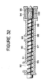
- Fig. 32 illustrates another known cavity transfer mixing extruder having a vent for discharging moisture and volatile substances contained in the materials.
- This cavity transfer mixing extruder comprises a barrel 90, a screw 91 coaxially and rotatably extended within the barrel 90, a housing 94 and a stator 95 fitted in the housing 94.
- the barrel 90 has an inlet opening 92 at the rear end and a vent 93 at the middle.
- the housing 94 is joined to the front end of the barrel 90.
- the screw 91 has a first feed section 96 corresponding to the inlet opening 92, a first metering section 97 extending behind the vent 93, a vent section 98 corresponding to the vent 93, a second metering section 99 before the stator 95, and a rotor section 100 corresponding to the stator 95.
- the housing 94, the stator 95 and the rotor section 100 constitute a cavity transfer mixing unit.
- the productivity of the cavity transfer mixing extruder of this type is dependent on the extruding capacity of the second extruding zone, namely, a section after the vent 93, which is reduced due to pressure drop in the cavity transfer mixing unit joined to the front end of the extruding unit. Furthermore, since heat is generated in the cavity transfer mixing unit due to the cavity transfer mixing action of the cavity transfer mixing unit, the rotating speed of the screw 91 has been limited to a certain level and it has been impossible to extrude a material having a viscosity exceeding a certain level.
- the respective cavities 23 and 24 of the stator and the rotor are formed so that the ridges 29 and 30 defining the opposite longitudinal edges of the cavities 23 and 24 extend parallel to the direction R1 of the rotation of the stator relative to the rotor and to the direction R2 of the rotation of the rotor relative to the stator. Consequently, any force that acts in a direction opposite the extrusion Z direction will not be produced.
- each of the cavities formed in the inner circumference of the stator and in the outer circumference of the rotor has, as viewed in a development, the shape of a parallelogram having a pair of opposite side extending in a direction perpendicular to the axial direction and a pair of opposite sides extending at an angle to the axial direction.
- an annular restricting member is provided detachably mounted at the junction of the screw and the mixing rotor so as to divide the extruding section and the mixing section.
- the screw and the mixing rotor are rotated by a motor, and a plurality of kinds of materials are fed through a feed opening into the cylinder 4 and are advanced by the screw.
- the screw is of the deep-groove type exterting an extrusive force on the materials at a small work rate, so that less heat is generated in the materials in the extruding unit. In some cases, air bubbles are formed in the materials in the extruding unit.
- annular restricting member dividing the extruding unit and the mixing unit increases the pressure of the materials in the front portion of the extruding unit, the air bubbles contained in the materials are eliminated. Since the annular restricting member is detachable, an annular restricting member having a diameter suitable for adjusting the pressure of the materials to a desired degree can be employed.
- a cavity transfer mixing extruder comprising a barrel having a feed opening in the rear end, a vent in the middle and an outlet opening in the front end, and a screw coaxially and rotatably extended within the barrel is provided with a cavity transfer mixing unit before the vent. Materials fed through the feed opening into the barrel is conveyed to the cavity transfer mixing unit, where the materials are melted and mixed. Then, moisture and volatile substances contained in the materials are discharged through the vent as the molten and mixed materials are conveyed further toward the outlet opening.
- the excellent mixing action and heat generating action of the cavity transfer mixing unit is utilized effectively for melting and mixing the materials, and hence the length of the first section necessary for plasticizing or melting the materials can be reduced. Furthermore, the molten or plasticized materials and the unmelted or unplasticized materials are mixed uniformly and efficiently by the excellent mixing performance of the cavity transfer mixing unit. Still further, since the cavity transfer mixing unit is provided in the first section, only a pressure corresponding to a pressure drop in the cavity transfer mixing unit is required for passing the materials through the cavity transfer mixing unit, the reduction of the extruding rate due to the provision of the cavity transfer mixing unit is limited to a small extent.
- Figures 1 to 9 are illustrations to assist in explaining a cavity transfer mixing extruder according to the present invention
- Figures 10 to 12 are illustrations to assist in explaining a conventional cavity transfer mixing extruder, in which:
- a cavity transfer mixing extruder comprising a first embodiment, of the present invention will be described hereinafter with reference to Fig. 1 to 8 particularly illustrating the cavity transfer mixing unit.
- a cylindrical housing 20 a cylindrical stator 21 fixedly fitted in the housing 20, and a generally cylindrical rotor 22 coaxially and rotatably extending within the stator 21.
- the rotor 22 is coupled at one end thereof with a extruding member, namely, a screw, not shown.
- the rotor 22 is rotated by a motor, not shown.
- a cavity group 27 comprising cavity rows 25 arranged along the axial direction (Y-Y) and each having a plurality of cavities 23 arranged side by side along the circumferential direction (X-X), and a cavity group 28 comprising cavity rows 26 arranged along the axial direction Y-Y and each having a plurality of cavities 24 arranged side by side along the circumferential direction X-X are formed in the inner circumference of the stator 21 (excluding the opposite ends of the stator 21) and in the outer circumference of the rotor 22 (excluding the opposite ends of the rotor 22), respectively.
- the respective cavities 23 and 24 of the cavity groups 27 and 28 are disposed at very small spacing so that the cavities are distributed densely.
- the cavity groups 27 and 28 are the same, when developed on a plane, in arrangement, shape and size except that the cavities 23 and 24 of the cavity groups 27 and 28 are inclined in opposite directions, respectively, with respet to the axial direction Y-Y.
- the cavities 23 of the cavity rows 25 of the cavity group 27 of the stator 21 are spaced by a distance ly corresponding to a half the axial pitch, namely, the axial interval between the adjacent cavity rows 25 and 26, relative to the corresponding cavities 24 of the cavity rgroup 26 of the rotor 22. Accordingly, the cavities 23 of each cavity row 25 of the cavity group 27 overlap the adjacent cavities 24 of the two adjacent cavity rows 26 of the cavity group 28.
- the cavities 23 and 24 each has a parallelogrammic shape defined by a pair of opposite, parallel straight walls 29 and 30 extending perpendicularly to the axial direction Y-Y, and a pair of opposite, parallel straight walls 31 and 32 extending at an angle to the axial direction Y-Y.
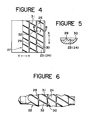
- the corners of the bottom surface of each one of cavities 23 and 24 is rounded as shown in Fig. 5 to prevent the stagnation of the material in the cavities 23 and 24.
- the respective longitudinal center axes 33 and 34 of the cavities 25 and 26 of the cavity groups 27 and 28 are inclined at the same angle ⁇ to the axial direction Y-Y to the left and to the right, respectively, with respect to the extrusion direction Z.
- the rotor 22 and the screw are rotated by the motor to squeeze a plurality of kinds highly viscous materials, such as plastics or rubbers, through the feed opening into the stator 21 by the screw.
- the materials thus squeezed into the stator are moved in the extrusion direction Z by the squeezing pressure applied thereto by the screw from the cavities 23 and 24 to the overlapping adjacent cavities 23 and 24. Since the rotor 22 is rotated, the materials are subjected to the complex combined action of deflective thrust force and circumferential shearing force as they are transferred from cavities 23 and 24 to the cavities 23 and 24, whereby materials which are different from each other in color or quality are mixed and dispersed uniformly.
- the cavities 23 and 24 are parallelogrammic cavities each are defined by a pair of the parallel straight walls 29 and 30, and pair of the parallel straight walls 31 and 32.
- the longitudinal axis of each cavity is inclined at an angle to the axial direction Y-Y, the materials filling the cavities 23 and 24 substantially in the extrusion direction Z by an additional force, which is different from the squeezing force produced by the screw, as the materials are sheared between the stator 21 and the rotor 22.
- the walls 29 and 30 are parallel to the circumferential direction of the stator 21 and the rotor 22, no force that acts on the materials in a direction opposite the direction of extrusion is produced, and hence the materials never staagnate within the cavities 23 and 24.
- the materials are advanced through the stator 21 by the combined action of the squeezing pressure produced by the screw, namely, the extruding member, and the pressure produced by the rotor 22, and the stagnation of the materials in the cavities 23 and 24 is prevented. Accordingly, the materials can be changed in a short time, and the loss of material in this changeover is reduced.
- the rotation of the rotor 22 reduces resistance against the flow of the materials through the stator 21, prevents the stagnation of the materials in the stator 21 effectively and reduces pressure drop in the stator 21. Consequently, the extrusion efficiency is improved, the extrusion rate is increased and the productivity is enhanced.
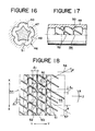
- a cold-feed type cavity transfer mixing extruder for rubber providing a second embodiment of the invention will be described hereinafter with reference to Figs. 15 to 20.
- Fig. 15 there are shown an extrusion unit 1 and a mixing unit 2 disposed after the extrusion unit 1 with respect to the extrusion direction Z
- the extrusion unit 1 comprises a barrel 4 provided with a feed opening 3, and a screw 5 coaxially extending through the barrel 4.
- the screw 5 is of a deep-groove type having a length shorter than the conventional screw. The screw is rotated by a motor, not shown.
- the mixing unit 2 comprises a stator assembly 6 consisting of a housing 8 and a stator 9 fitted in the housing 8, and a rotor 7 coaxially extended through the stator 9.
- the rotor 7 is joined detachably to the front end of the screw 5 by screwing the threaded portion of the same into the screw 5.
- a cavity group 14 comprising cavity rows 12 arranged along the axial direction Y-Y and each having a plurality of cavities 10 arranged side by side along the circumferential direction X-X
- a cavity group 15 comprising cavity rows 13 arranged along the axial direction Y-Y and each having a plurality of cavities 11 arranged side by side along the circumferential direction X-X are formed in the inner circumference of the stator 9 and in the outer circumference of the rotor 7, respectively.
- the respective cavities 10 and 11 of the cavity groups 14 and 15 are arranged at very small intervals so that the cavities are distributed densely.
- the respective cavities 10 and 11 of the succeeding cavity rows 14 and 15 of the cavity groups 14 and 15 are spaced by distance lx in the circumferential direction in the respective directions of relative rotation of the cavity groups 14 and 15, namely, in a direction opposite the direction R of rotation of the rotor 7 for the cavity groups 14 of the stator 9 and in the direction R of rotation of the rotor 7 for the cavity group 15 of the rotor 7, relative to the respective adjacent cavities 10 and 1 of the adjacent preceding cavity rows 12 and 13, respectively.
- the cavities 10 and 11 are densely distributed by shifting the respective cavities 10 and 11 of the succeeding cavity rows 12 and 13 relative to the adjacent cavities 10 and 11 of the preceding cavity rows, respectively.
- the relative distribution of the cavities 10 and 11, and shape of the cavities, and the inclination of the longitudinal axes of the cavities 10 and 11 are the same as those of the first embodiment.
- an annular restricting member 18 is fitted detachably on the rear portion of the rotor 7, and is held fixedly between the rotor 7 and the screw 5.
- the restricting member 18 has an outside diameter greater than those of the screw 5 and the rotor 7, so that the extrusion unit 1 and the mixing unit 2 are divided by the restricting member 18.
- Fig. 20 illustrates another restricting member according to the present invention.
- This restricting member 18 is provided with axial grooves 19 formed in the circumference thereof at regular angular intervals to facilitate the passage of the materials across the restricting member 18 from the extrusion unit 1 into the mixing unit 2. Therefore, this restricting member 18 is effective for preventing the burning of the materials, particularly, in extruding the mixing highly viscous materials such as rubbers.
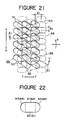
- a cold-feed type cavity transfer mixing extruder comprising a third embodiment, of the present invention will be described hereinafter with reference to Fig. 21 and 22.
- the constitution of the third embodiment is substantially the same as that of the second embodiment, except that the respective cavities 10 and 11 of the stator 6 and the rotor 7 are different from those of the second embodiment. Accordingly, the third embodiment will be described only in terms of the shape and distribution of the cavities 10 and 11.
- the cavities 10 and 11 have the same oblong shape.
- the cavities 10 and 11 consists of rectangular sections 21 and 22, and a pair of semicircular sections 23 and a pair of semicircular sections 24 joined to the opposite axial ends of the rectangular sections 21 and 22, respectively.
- Only the cavities 11 of the rotor 7 each has a longitudinal axis inclined at an angle ⁇ with respect to the axial direction Y-Y.
- the cavities 10 of the stator 6 are arranged so that the circumferential distance lx' between the center of the cavity 10 of one of the cavity rows 12 and the center of the adjacent cavity 10 of the adjacent cavity row 12 is a half the circumferential distance between the respective centers of the cavities of the same cavity row 12.
- the distance lx' is considerably greater than the circumferential distance lx between the center of the cavity 11 of one of the cavity rows 13 and the center of the adjacent cavity 11 of the adjacent cavity row 13.
- cavities 10 of the stator 6, instead of the cavities 11 of the rotor 7, may be inclined with respect to the axial direction Y-Y, and the cavities 10 and 11 may be elliptic cavities.
- the cold-feed type cavity transfer mixing extruder has a screw having an L/D ratio of eight, a stator provided with three cavity rows, and a rotor provided with three cavity rows.
- Blue natural rubber compound ribbons and yellow natural rubber compound ribbons (Mooney viscosity MLH4: 60 at 100°C) were subjected to experimental mixing extrusion on the cold-feed type cavity transfer mixing extruder. The results of the experimental operation are shown in Fig. 23 showing the variations of the extrusion rate and extrusion temperature with the rotating speed of the screw and the rotor.
- the extrusion rate was 580 kg/hr and the extrusion temperature, namely, the temperature of the materials extruded, was 93°C, when the rotating speed of the screw and the rotor was 80 rpm.
- Well mixed and kneaded green natural rubber compound having a small variation in temperature distribution was obtained.
- the rubber compounds were mixed satisfactorily, the extrusion temperature remained at a low level, and the temperature variation in the extruded compound was as small as ⁇ 1°C, regardless of the rotating speed of the screw and the rotor. It was proved that the performance of the cold-feed type cavity transfer mixing extruder incorporating the present invention is superior to that of the conventional cold-feed type cavity transfer mixing extruder.
- the heat generation of the cavity transfer mixing extruder can be reduced even in mixing and extruding highly viscous materials without sacrificing the degree of mixing and productivity, and even materials which required the severe restriction on the extrusion temperature can be uniformly and satisfactorily mixed and extruded at high efficiency.
- the provision of the restricting member between the screw and the rotor prevents materials containing air bubbles being squeezed into the mixing unit.
- the restricting member is detachable, the squeezing pressure can be adjusted to a desired value by choosing a suitable restricting member from among a plurality of spare restricting members.
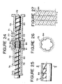
- a cavity transfer mixing extruder comprising a fourth embodiment, of the present invention will be described hereinafter with reference to Figs. 24 and 31.
- a cavity transfer mixing extruder comprising a fourth embodiment of the present invention, comprising a barrel 1 consisting of a first barrel section 2 and a second barrel section 3, a housing 4 disposed between and fixedly joined to the first and second barrel sections 2 and 3, a stator 5 fixedly fitted in the housing 4, and a screw shaft 9 coaxially and rotatably extending through the barrel 1.
- a feed opening y is formed at the rear end of the first barrel section 2; a vent 7 is formed at the rear end, namely, at a position near the housing 4, of the second barrel section 3; an outlet opening 8 is formed at the front end of the second barrel section 3.
- a die, not shown, is attached to the front end of the second barrel section 3.
- the screw shaft 9 has a first screw section 10 corresponding to the first barrel section 2, a rotor section 11 corresponding to the stator 5, a second screw section 12 corresponding to a portion having the vent 7 of the second barrel section 3, and a matering screw section 13 corresponding to the front portion of the second barrel section 3.
- the housing 4, the stator 5 and the rotor section 11 constitute a mixing unit.
- the stator 5 is provided at its inner circumferencial portion with cavities 14 each having a longitudinal axis extending at an angle to the axial direction Y-Y as viewed in a development best shown in Fig. 27.
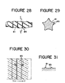
- the rotor section 11 is provided at its outer circumferencial portion with cavities 15 each having a longitudinal axis extending at an angle to the axial direction Y-Y as viewed in a development best shown in Fig. 30.
- the relative circumferential movement of the cavities 14 and 15 causes the material to advance.
- the cavities 14 and 15 are formed close to each other, respectively, so that the upper surfaces of the lands, namely, the walls, defining the cavities 14 and 15 are of small width to reduce the pressure loss due to the resistance of the inner circumference of the stator 5 and the outer circumference of the rotor section 11 against the flow of the material to the least extent in order that heat generation in the mixing unit attributable to the resistance of the stator 5 and the rotor section 11 against the flow of the material is reduced.
- the raw rubber compounds fed through the feed opening are pushed forward by the first screw section 10 into the mixing unit, where the raw rubber compounds are mixed between the respective cavities 14 and 15 of the stator 5 and the rotor section 11, and are plasticized by being heated uniformly. While the mixed rubber compounds are pushed forward by the second screw section 12, moisture and volatile substances contained in the mixed rubber compounds are discharged through the vent 7. Then, the mixed rubber compounds thus deaerated are pushed further forward, and then the mixed rubber compounds are extruded through the die, not shown, after passing the metering section 13.
- the material are urged forward by the lands of the cavities 14 and 15 as the screw shaft 9 is rotated. Accordingly, the pressure loss and the increase of temperature in the mixing unit is reduced; consequently, the screw shaft 9 may be rotated at a high rotating speed to enhance the productivity of the cavity transfer mixing extruder even when mixing and extruding materials which requires the processing temperature to be kept below a certain level to prevent scorching, such as rubber compounds.
- the cavity transfer mixing extruder of the present invention requires less time for changing the materials as compared with the conventional cavity transfer mixing extruder employing semispherical cavities.
- the first screw section 10 In mixing and extruding plastics with the cavity transfer mixing extruder, it is desirable to provide the first screw section 10 with a compressing unit in order that the plasticization and melting of the plastics are accelerated by the shearing action of the first screw section 10.
- the cavity transfer mixing extruder of the present invention is able to extrude a satisfactory mixed rubber compound of uniform temperature even when a deep grooved screw is employed as the first screw section, because the air bubbles are discharged through the vent while the mixed rubber compounds are advanced by the second screw section.
- the cavities may be semispherical cavities or oblong cavities.
Abstract
Description
- The present invention relates to a cavity transfer mixing extruder for uniformly mixing and extruding highly viscous materials, such as molten plastics or fluid rubbers, and, more specifically, to a cavity transfer mixing extruder having a stator provided with cavities of improved shape in the inner circumference and a rotor provided with cavities of improved shape in the outer circumference, and capable of achieving satisfactory extrusion of the materials.
- Cavity transfer mixing extruders for uniformly mixing and extruding highly viscous materials, such as molten plastics or fluid rubbers, are disclosed in Japanese Patent Provisional Publication Nos. 60-107306 and 57-87344.
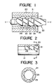
- The cavity transfer mixing extruder disclosed in Japanese Patent Provisional Publication No. 60-107306 is illustrated in Figs. 10 to 12. As illustrated in Fig. 10, the cavity transfer mixing extruder has a cylindrical housing 1, a
cylindrical stator 2 fixedly fitted in the cylindrical housing 1, acylindrical rotor 3 coaxially and rotatably extended within thestator 2. Therotor 3 is connected at one end thereof to an extruding member such as a screw shaft, and is driven for rotation by a motor. - As illustrated in Fig. 12, a group of
cavities 8 comprising cavity rows 6 arranged along the axial direction Y-Y and each having a plurality ofcavities 4 arranged side by side along the circumferential direction X-X, and acavity group 9 comprising cavity rows 7 arranged along the axial direction Y-Y and each having a plurality ofcavities 5 arranged side by side along the circumferential direction X-X are formed in the inner circumference of thestator 2 excluding the opposite ends thereof and in the outer circumference of therotor 3 excluding the opposite ends thereof, respectively. Therespective cavities cavity groups cavities - The
respective cavities cavity groups cavity groups rotor 3 for thecavity group 8 of thestator 2 and in the direction R of rotation of therotor 3 for thecavity group 9 of therotor 3, relative to the respectiveadjacent cavities - The
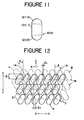
cavities 4 of the cavity rows 6 of thecavity group 8 of thestator 2 are spaced by a distance ℓy corresponding to a half the axial pitch (interval along the axial direction Y-Y) of the cavity rows 6 and 7 relative to thecorresponding cavities 5 of thecavity group 9 of therotor 3. Accordingly, thecavities 4 of each cavity row 6 ofth cavity group 8 overlap theadjacent cavities 5 of the two adjacent cavity rows 7 of thecavity group 9. - As illustrated in Fig. 11, each cavity 4 (5) has an oblong shape consisting of a rectangular section 10 (11) and a pair of semicircular sections 12 (13) formed at the opposite ends of the rectangular section 10 (11). The
respective center axes cavities cavity groups - In mixing operation, the
rotor 3 and the extruding member are rotated by the motor to press a plurality of highly viscous materials, such as molten plastics or fluid rubbers through the inlet into thestator 2. Then, the mateials are moved in the extrusion direction Z from thecavities cavities rotor 3 is rotating, the materials which differ in quality or color are dispersed and mixed uniformly as they are transferred from thecavities adjacent cavities oblong cavities stator 2 and that of the outer circumference of therotor 2, thecavities 4 of thestator 2 move in the direction of the arrow R1 relative to the outer circumference of therotor 3, while thecavities 5 of therotor 3 move in the direction of the arrow R2 relative to the inner circumference of thestator 2. Then, the materials filling thecavities cavities cavities cavities cavities 4 and in portions B in thecavities 5. This phenomenon will be understood more clearly when theoblong cavities oblong cavities - Fig. 32 illustrates another known cavity transfer mixing extruder having a vent for discharging moisture and volatile substances contained in the materials. This cavity transfer mixing extruder comprises a
barrel 90, ascrew 91 coaxially and rotatably extended within thebarrel 90, ahousing 94 and astator 95 fitted in thehousing 94. Thebarrel 90 has an inlet opening 92 at the rear end and avent 93 at the middle. Thehousing 94 is joined to the front end of thebarrel 90. Thescrew 91 has afirst feed section 96 corresponding to the inlet opening 92, afirst metering section 97 extending behind thevent 93, avent section 98 corresponding to thevent 93, asecond metering section 99 before thestator 95, and arotor section 100 corresponding to thestator 95. Thehousing 94, thestator 95 and therotor section 100 constitute a cavity transfer mixing unit. - Generally, the productivity of the cavity transfer mixing extruder of this type is dependent on the extruding capacity of the second extruding zone, namely, a section after the
vent 93, which is reduced due to pressure drop in the cavity transfer mixing unit joined to the front end of the extruding unit. Furthermore, since heat is generated in the cavity transfer mixing unit due to the cavity transfer mixing action of the cavity transfer mixing unit, the rotating speed of thescrew 91 has been limited to a certain level and it has been impossible to extrude a material having a viscosity exceeding a certain level. - Still further, since the first zone extending before the
vent 93 needs to be sufficiently long to heat the material so that the material is sufficiently plasticized, an elongate screw having a very large L/D ratio, for example, and L/D ratio in the range of 18 to 20 for rubber and in the range of 28 to 35 for plastics, is necessary, which is disadvantageous in respect of mechanical stability. - We will describe a cavity transfer mixing extruder having cavities capable of always causing the material to move in the extrusion direction.
- We will describe a cavity transfer mixing extruder having a vent, capable of operating at a high extrusion rate regardless of the type of materials and having a short extrusion screw as compared with the conventional extrusion screw.
- According to one aspect of the present invention, as illustrated in Fig. 9, the
respective cavities ridges cavities - According to another aspect of the invention, an annular restricting member is provided detachably mounted at the junction of the screw and the mixing rotor so as to divide the extruding section and the mixing section. In operation, the screw and the mixing rotor are rotated by a motor, and a plurality of kinds of materials are fed through a feed opening into the
cylinder 4 and are advanced by the screw. The screw is of the deep-groove type exterting an extrusive force on the materials at a small work rate, so that less heat is generated in the materials in the extruding unit. In some cases, air bubbles are formed in the materials in the extruding unit. However, since the annular restricting member dividing the extruding unit and the mixing unit increases the pressure of the materials in the front portion of the extruding unit, the air bubbles contained in the materials are eliminated. Since the annular restricting member is detachable, an annular restricting member having a diameter suitable for adjusting the pressure of the materials to a desired degree can be employed. - According to the further aspect of the present invention, a cavity transfer mixing extruder comprising a barrel having a feed opening in the rear end, a vent in the middle and an outlet opening in the front end, and a screw coaxially and rotatably extended within the barrel is provided with a cavity transfer mixing unit before the vent. Materials fed through the feed opening into the barrel is conveyed to the cavity transfer mixing unit, where the materials are melted and mixed. Then, moisture and volatile substances contained in the materials are discharged through the vent as the molten and mixed materials are conveyed further toward the outlet opening. Thus, in the first section before the vent, the excellent mixing action and heat generating action of the cavity transfer mixing unit is utilized effectively for melting and mixing the materials, and hence the length of the first section necessary for plasticizing or melting the materials can be reduced. Furthermore, the molten or plasticized materials and the unmelted or unplasticized materials are mixed uniformly and efficiently by the excellent mixing performance of the cavity transfer mixing unit. Still further, since the cavity transfer mixing unit is provided in the first section, only a pressure corresponding to a pressure drop in the cavity transfer mixing unit is required for passing the materials through the cavity transfer mixing unit, the reduction of the extruding rate due to the provision of the cavity transfer mixing unit is limited to a small extent.
- The above and other objects, features and advantages of the present invention will become more apparent from the following description taken in conjunction with the accompanying drawings.
- Figures 1 to 9 are illustrations to assist in explaining a cavity transfer mixing extruder according to the present invention, and Figures 10 to 12 are illustrations to assist in explaining a conventional cavity transfer mixing extruder, in which:
- Figure 1 is a longitudinal sectional view of a cavity transfer mixing unit, comprising a preferred embodiment, of the present invention;
- Figure 2 is a partially sectional side elevation of a stator;
- Figure 3 is a sectional view taken on line A-A in Fig. 2;
- Figure 4 is a development of a portion of the inner circumference of the stator of Fig. 2;
- Figure 5 is a sectional view taken on line B-B in Fig. 4;
- Figure 6 is a side elevation of a rotor;
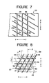
- Figure 7 is a development of a portion of the outer circumference of the rotor of Fig. 6;
- Figure 8 is a development showing the relative disposition of the cavity groups;
- Figure 9 is an illustration to assist in explaining the action of cavities according to the present invention;
- Figure 10 is a fragmentary longitudinal sectional view of a conventional cavity transfer mixing unit;
- Figure 11 is an enlarged view of a cavity of the cavity transfer mixing unit of Fig. 10;
- Figure 12 is a development showing the relative disposition of the cavity groups of the cavity transfer mixing unit of Fig. 10;
- Figures 13 and 14 are illustrations to assist in explaining the action of the conventional cavities;
- figure 15 is a fragmentary longitudinal sectional view of a cavity transfer mixing extruder, comprising a second embodiment according to the present invention;
- Figure 16 is a sectional view taken on line A-A in Fig. 15;
- Figure 17 is a partially sectional view of the stator of the cavity transfer mixing extruder of Fig. 15;
- Figure 18 is a development showing the disposition of the cavity groups of the cavity transfer mixing extruder of Fig. 15;
- Figure 19 is a fragmentary sectional view of a portion of the cavity transfer mixing extruder of Fig. 15, provided with an annular restricting member;
- Figure 20 is a fragmentary cutaway view showing another annular restricting member;
- Figure 21 is a development showing the disposition of cavity groups of a cavity transfer mixing extruder comprising a third embodiment, of the present invention;
- Figure 22 is an enlarged plan view of a cavity employed in the the third embodiment;
- Figure 23 is a graph showing the variations of extrusion rate and extrusion temperature with the rotating speed of the screw;
- Figure 24 is a longitudinal sectional view of a cavity transfer mixing extruder, comprising a fourth embodiment, of the present invention;
- Figure 25 is a partially sectional view of the stator of the fourth embodiment;
- Figure 26 is a sectional view taken on line B-B in Fig. 25;
- Figure 27 is a development of the inner circumference of the stator of the fourth embodiment;
- Figure 28 is a fragmentary side elevation of the rotor of the fourth embodiment;
- Figure 29 is a sectional view taken on line C-C in Fig. 28;
- Figure 30 is a development of the outer circumference of the rotor of the fourth embodiment;
- Figure 31 is a sectional view taken on line D-D in Fig. 31; and
- Figure 32 is a longitudinal sectional view of a conventional cavity transfer mixing extruder.
- A cavity transfer mixing extruder, comprising a first embodiment, of the present invention will be described hereinafter with reference to Fig. 1 to 8 particularly illustrating the cavity transfer mixing unit.
- In Fig. 1, there are shown a
cylindrical housing 20, acylindrical stator 21 fixedly fitted in thehousing 20, and a generallycylindrical rotor 22 coaxially and rotatably extending within thestator 21. Therotor 22 is coupled at one end thereof with a extruding member, namely, a screw, not shown. Therotor 22 is rotated by a motor, not shown. - As illustrated in Figs. 2 to 8, a
cavity group 27 comprisingcavity rows 25 arranged along the axial direction (Y-Y) and each having a plurality ofcavities 23 arranged side by side along the circumferential direction (X-X), and acavity group 28 comprisingcavity rows 26 arranged along the axial direction Y-Y and each having a plurality ofcavities 24 arranged side by side along the circumferential direction X-X are formed in the inner circumference of the stator 21 (excluding the opposite ends of the stator 21) and in the outer circumference of the rotor 22 (excluding the opposite ends of the rotor 22), respectively. Therespective cavities cavity groups cavities cavity groups - As best shown in Fig. 8, the
cavities 23 of thecavity rows 25 of thecavity group 27 of thestator 21 are spaced by a distance ℓy corresponding to a half the axial pitch, namely, the axial interval between theadjacent cavity rows cavities 24 of thecavity rgroup 26 of therotor 22. Accordingly, thecavities 23 of eachcavity row 25 of thecavity group 27 overlap theadjacent cavities 24 of the twoadjacent cavity rows 26 of thecavity group 28. - When developed on a plane, the
cavities straight walls straight walls cavities cavities - The respective longitudinal center axes 33 and 34 of the
cavities cavity groups - In operation, the
rotor 22 and the screw are rotated by the motor to squeeze a plurality of kinds highly viscous materials, such as plastics or rubbers, through the feed opening into thestator 21 by the screw. The materials thus squeezed into the stator are moved in the extrusion direction Z by the squeezing pressure applied thereto by the screw from thecavities adjacent cavities rotor 22 is rotated, the materials are subjected to the complex combined action of deflective thrust force and circumferential shearing force as they are transferred fromcavities cavities - Since the
cavities straight walls straight walls cavities stator 21 and therotor 22. Since thewalls stator 21 and therotor 22, no force that acts on the materials in a direction opposite the direction of extrusion is produced, and hence the materials never staagnate within thecavities - Thus, the materials are advanced through the
stator 21 by the combined action of the squeezing pressure produced by the screw, namely, the extruding member, and the pressure produced by therotor 22, and the stagnation of the materials in thecavities - Furthermore, the rotation of the
rotor 22 reduces resistance against the flow of the materials through thestator 21, prevents the stagnation of the materials in thestator 21 effectively and reduces pressure drop in thestator 21. Consequently, the extrusion efficiency is improved, the extrusion rate is increased and the productivity is enhanced. - Still further, since the resistance against the flow of the materials through the
stator 21 is reduced, heat generation in the materials is mitigated, which enables the satisfactory mixing of materials sensitive to heat. - A cold-feed type cavity transfer mixing extruder for rubber, providing a second embodiment of the invention will be described hereinafter with reference to Figs. 15 to 20.
- In Fig. 15, there are shown an extrusion unit 1 and a
mixing unit 2 disposed after the extrusion unit 1 with respect to the extrusion direction Z The extrusion unit 1 comprises abarrel 4 provided with afeed opening 3, and ascrew 5 coaxially extending through thebarrel 4. Thescrew 5 is of a deep-groove type having a length shorter than the conventional screw. The screw is rotated by a motor, not shown. - As illustrated in Fig. 15, the mixing
unit 2 comprises a stator assembly 6 consisting of ahousing 8 and astator 9 fitted in thehousing 8, and a rotor 7 coaxially extended through thestator 9. The rotor 7 is joined detachably to the front end of thescrew 5 by screwing the threaded portion of the same into thescrew 5. - As illustrated in Fig. 18, a
cavity group 14 comprisingcavity rows 12 arranged along the axial direction Y-Y and each having a plurality ofcavities 10 arranged side by side along the circumferential direction X-X, and acavity group 15 comprisingcavity rows 13 arranged along the axial direction Y-Y and each having a plurality ofcavities 11 arranged side by side along the circumferential direction X-X are formed in the inner circumference of thestator 9 and in the outer circumference of the rotor 7, respectively. Therespective cavities cavity groups - The
respective cavities cavity rows cavity groups cavity groups cavity groups 14 of thestator 9 and in the direction R of rotation of the rotor 7 for thecavity group 15 of the rotor 7, relative to the respectiveadjacent cavities 10 and 1 of the adjacent precedingcavity rows cavities respective cavities cavity rows adjacent cavities - The relative distribution of the
cavities cavities - As illustrated in Fig. 19, an annular restricting member 18 is fitted detachably on the rear portion of the rotor 7, and is held fixedly between the rotor 7 and the
screw 5. The restricting member 18 has an outside diameter greater than those of thescrew 5 and the rotor 7, so that the extrusion unit 1 and themixing unit 2 are divided by the restricting member 18. - Fig. 20 illustrates another restricting member according to the present invention. This restricting member 18 is provided with axial grooves 19 formed in the circumference thereof at regular angular intervals to facilitate the passage of the materials across the restricting member 18 from the extrusion unit 1 into the
mixing unit 2. Therefore, this restricting member 18 is effective for preventing the burning of the materials, particularly, in extruding the mixing highly viscous materials such as rubbers. - A cold-feed type cavity transfer mixing extruder, comprising a third embodiment, of the present invention will be described hereinafter with reference to Fig. 21 and 22.
- The constitution of the third embodiment is substantially the same as that of the second embodiment, except that the
respective cavities cavities - The
cavities cavities rectangular sections semicircular sections 23 and a pair ofsemicircular sections 24 joined to the opposite axial ends of therectangular sections cavities 11 of the rotor 7 each has a longitudinal axis inclined at an angle ϑ with respect to the axial direction Y-Y. - The
cavities 10 of the stator 6 are arranged so that the circumferential distance ℓx' between the center of thecavity 10 of one of thecavity rows 12 and the center of theadjacent cavity 10 of theadjacent cavity row 12 is a half the circumferential distance between the respective centers of the cavities of thesame cavity row 12. The distance ℓx' is considerably greater than the circumferential distance ℓx between the center of thecavity 11 of one of thecavity rows 13 and the center of theadjacent cavity 11 of theadjacent cavity row 13. - Only the
cavities 10 of the stator 6, instead of thecavities 11 of the rotor 7, may be inclined with respect to the axial direction Y-Y, and thecavities - The performance of a cold-feed type cavity transfer mixing extruder incorporating the present invention was confirmed experimentally.
- The cold-feed type cavity transfer mixing extruder has a screw having an L/D ratio of eight, a stator provided with three cavity rows, and a rotor provided with three cavity rows. Blue natural rubber compound ribbons and yellow natural rubber compound ribbons (Mooney viscosity MLH4: 60 at 100°C) were subjected to experimental mixing extrusion on the cold-feed type cavity transfer mixing extruder. The results of the experimental operation are shown in Fig. 23 showing the variations of the extrusion rate and extrusion temperature with the rotating speed of the screw and the rotor.
- It is known from Fig. 23 that the extrusion rate was 580 kg/hr and the extrusion temperature, namely, the temperature of the materials extruded, was 93°C, when the rotating speed of the screw and the rotor was 80 rpm. Well mixed and kneaded green natural rubber compound having a small variation in temperature distribution was obtained. The rubber compounds were mixed satisfactorily, the extrusion temperature remained at a low level, and the temperature variation in the extruded compound was as small as ± 1°C, regardless of the rotating speed of the screw and the rotor. It was proved that the performance of the cold-feed type cavity transfer mixing extruder incorporating the present invention is superior to that of the conventional cold-feed type cavity transfer mixing extruder.
- When the cold-feed type cavity transfer mixing extruder was operated without the restricting member 18, some air bubbles were contained in the extruded rubber compound.
- Thus, according to the present invention, the heat generation of the cavity transfer mixing extruder can be reduced even in mixing and extruding highly viscous materials without sacrificing the degree of mixing and productivity, and even materials which required the severe restriction on the extrusion temperature can be uniformly and satisfactorily mixed and extruded at high efficiency. The provision of the restricting member between the screw and the rotor prevents materials containing air bubbles being squeezed into the mixing unit. Furthermore, since the restricting member is detachable, the squeezing pressure can be adjusted to a desired value by choosing a suitable restricting member from among a plurality of spare restricting members.
- A cavity transfer mixing extruder, comprising a fourth embodiment, of the present invention will be described hereinafter with reference to Figs. 24 and 31.
- In Fig. 24, there is shown a cavity transfer mixing extruder comprising a fourth embodiment of the present invention, comprising a barrel 1 consisting of a
first barrel section 2 and asecond barrel section 3, ahousing 4 disposed between and fixedly joined to the first andsecond barrel sections stator 5 fixedly fitted in thehousing 4, and ascrew shaft 9 coaxially and rotatably extending through the barrel 1. A feed opening y is formed at the rear end of thefirst barrel section 2; a vent 7 is formed at the rear end, namely, at a position near thehousing 4, of thesecond barrel section 3; anoutlet opening 8 is formed at the front end of thesecond barrel section 3. A die, not shown, is attached to the front end of thesecond barrel section 3. - The
screw shaft 9 has afirst screw section 10 corresponding to thefirst barrel section 2, arotor section 11 corresponding to thestator 5, asecond screw section 12 corresponding to a portion having the vent 7 of thesecond barrel section 3, and amatering screw section 13 corresponding to the front portion of thesecond barrel section 3. - The
housing 4, thestator 5 and therotor section 11 constitute a mixing unit. - As illustrated in Figs. 25 to 27, the
stator 5 is provided at its inner circumferencial portion withcavities 14 each having a longitudinal axis extending at an angle to the axial direction Y-Y as viewed in a development best shown in Fig. 27. - As illustrated in Figs. 28 to 31, the
rotor section 11 is provided at its outer circumferencial portion withcavities 15 each having a longitudinal axis extending at an angle to the axial direction Y-Y as viewed in a development best shown in Fig. 30. - Thus, the relative circumferential movement of the
cavities cavities cavities stator 5 and the outer circumference of therotor section 11 against the flow of the material to the least extent in order that heat generation in the mixing unit attributable to the resistance of thestator 5 and therotor section 11 against the flow of the material is reduced. - In mixing and extruding raw rubber compounds on the cavity transfer mixing extruder, the raw rubber compounds fed through the feed opening are pushed forward by the
first screw section 10 into the mixing unit, where the raw rubber compounds are mixed between therespective cavities stator 5 and therotor section 11, and are plasticized by being heated uniformly. While the mixed rubber compounds are pushed forward by thesecond screw section 12, moisture and volatile substances contained in the mixed rubber compounds are discharged through the vent 7. Then, the mixed rubber compounds thus deaerated are pushed further forward, and then the mixed rubber compounds are extruded through the die, not shown, after passing themetering section 13. - Since the
respective cavities stator 5 and therotor section 11 are arranged with their longitudinal axes inclined at an angle to the axial direction Y-Y, the material are urged forward by the lands of thecavities screw shaft 9 is rotated. Accordingly, the pressure loss and the increase of temperature in the mixing unit is reduced; consequently, thescrew shaft 9 may be rotated at a high rotating speed to enhance the productivity of the cavity transfer mixing extruder even when mixing and extruding materials which requires the processing temperature to be kept below a certain level to prevent scorching, such as rubber compounds. Furthermore, since thecavities - In mixing and extruding plastics with the cavity transfer mixing extruder, it is desirable to provide the
first screw section 10 with a compressing unit in order that the plasticization and melting of the plastics are accelerated by the shearing action of thefirst screw section 10. - In mixing and extruding rubbers, the use of a combination of a deep grooved screw and the mixing unit enhances the extrusion rate remarkably, whereas it is possible, with some kinds of rubber compounds, that air bubbles are formed in the mixed rubber compounds. However, the cavity transfer mixing extruder of the present invention is able to extrude a satisfactory mixed rubber compound of uniform temperature even when a deep grooved screw is employed as the first screw section, because the air bubbles are discharged through the vent while the mixed rubber compounds are advanced by the second screw section.
- Although the parallelogrammic cavities are most desirable, the cavities may be semispherical cavities or oblong cavities.
- Although the invention has been described in its preferred forms with a certain degree of particularity, it is to be understood that many variations and changes are possible in the invention without departing from the scope and spirit thereof.
Claims (3)
a mixing unit comprising: a housing; a stator fixedly fitted in the housing and provided with a first cavity group including circumferential cavity rows of cavities in the inner circumference thereof excluding the opposite ends thereof; and a rotor joined coaxially to the front end of the screw shaft, coaxially and rotatably extended through the stator, and provided with a second cavity group including circumferential cavity rows of cavities in the outer circumference thereof excluding the opposite ends thereof,
characterized in that the respective cavities of the first and second cavity groups, when developed on a plane, each has a parallelogrammic shape defined by a pair of opposite, parallel straight walls extending perpendicularly to the axial direction, and a pair of opposite, parallel straight walls inclined at an angle to the axial direction; the longitudinal axes of the cavities of the first cavity group and the longitudinal axes of the cavities of the second cavity group are inclined in opposite directions with respect to the axial direction; the cavity rows of the first cavity group and the cavity rows of the second cavity group have the same axial pitch; and the cavity rows of the first cavity group are shifted axially relative to the cavity rows of the second cavity group by a distance corresponding to a half the axial pitch so that each cavity of each cavity row of the first cavity group overlaps the adjacent cavities of the adjacent cavity rows of the second cavity group.
Applications Claiming Priority (6)
| Application Number | Priority Date | Filing Date | Title |
|---|---|---|---|
| JP229573/85 | 1985-10-14 | ||
| JP60229573A JPS6287308A (en) | 1985-10-14 | 1985-10-14 | Mixer for extrusion |
| JP1986025998U JPS62138015U (en) | 1986-02-24 | 1986-02-24 | |
| JP25998/86 | 1986-02-24 | ||
| JP33484/86 | 1986-03-07 | ||
| JP1986033484U JPS62144621U (en) | 1986-03-07 | 1986-03-07 |
Publications (3)
| Publication Number | Publication Date |
|---|---|
| EP0219334A2 true EP0219334A2 (en) | 1987-04-22 |
| EP0219334A3 EP0219334A3 (en) | 1988-03-16 |
| EP0219334B1 EP0219334B1 (en) | 1991-01-09 |
Family
ID=27285229
Family Applications (1)
| Application Number | Title | Priority Date | Filing Date |
|---|---|---|---|
| EP86307883A Expired - Lifetime EP0219334B1 (en) | 1985-10-14 | 1986-10-10 | Cavity transfer mixing extruder |
Country Status (4)
| Country | Link |
|---|---|
| US (1) | US4695165A (en) |
| EP (1) | EP0219334B1 (en) |
| KR (1) | KR900001957B1 (en) |
| DE (1) | DE3676779D1 (en) |
Cited By (7)
| Publication number | Priority date | Publication date | Assignee | Title |
|---|---|---|---|---|
| GB2202785A (en) * | 1987-02-27 | 1988-10-05 | Reifenhaeuser Masch | Apparatus for blending of thermoplasticised synthetic materials |
| GB2216844A (en) * | 1988-04-08 | 1989-10-18 | Reifenhaeuser Masch | Cavity transfer mixer device for extrusion blending thermoplasticised synthetic materials. |
| GB2216843A (en) * | 1988-04-08 | 1989-10-18 | Reifenhaeuser Masch | Blending thermoplasticised synthetic materials, with additives pumped into a cavity transfer mixer. |
| EP0490360A1 (en) * | 1990-12-14 | 1992-06-17 | HERMANN BERSTORFF Maschinenbau GmbH | Method and extruder for the processing and the manufacture of rubber and plastic materials |
| EP0490058A1 (en) * | 1990-12-14 | 1992-06-17 | HERMANN BERSTORFF Maschinenbau GmbH | Extruder with a high capacity |
| EP0666161A2 (en) * | 1994-01-29 | 1995-08-09 | Röhm GmbH | Method for short-term treatment of thermoplastic molten material with a fluid treating agent and obtained thermoplastic material |
| US7255472B2 (en) | 2002-10-21 | 2007-08-14 | Basf Aktiengesellschaft | Mixing device with mixing ring having offset channels with spaced baffles |
Families Citing this family (17)
| Publication number | Priority date | Publication date | Assignee | Title |
|---|---|---|---|---|
| US5094058A (en) * | 1988-04-01 | 1992-03-10 | Slocum Donald H | Roofing shingle |
| US4840492A (en) * | 1988-04-25 | 1989-06-20 | Kensaku Nakamura | Rotational screw for mixing |
| FR2664197B1 (en) * | 1990-07-06 | 1994-05-06 | Clextral | SHEATH FOR MATERIAL EXTRUSION MACHINE. |
| DE4137969C1 (en) * | 1990-12-14 | 1992-10-15 | Berstorff Gmbh Masch Hermann | |
| US5267847A (en) * | 1990-12-24 | 1993-12-07 | Bridgestone Corporation | Compact precision extrusion system |
| US5178458A (en) * | 1991-03-08 | 1993-01-12 | Cincinnati Milacron Inc. | Extruder screw mixing head |
| GB2254283B (en) * | 1991-03-26 | 1995-02-15 | Frenkel Ag C D | Improvements in plasticising units for screw injection moulding machines |
| DE4301431C2 (en) * | 1992-02-27 | 1996-03-14 | Mitsubishi Heavy Ind Ltd | Two-stage extruder |
| US5356281A (en) * | 1992-08-10 | 1994-10-18 | Three Bond Co., Ltd. | Screw-type resin injection apparatus for injection molding |
| ZA9510847B (en) * | 1994-12-23 | 1997-06-20 | Unilever Plc | Process for the production of liquid compositions |
| US5957576A (en) * | 1995-06-30 | 1999-09-28 | Sumitomo Bakelite Company Limited | Screw for in-line screw type thermosetting resin injection molding machine |
| AT405537B (en) * | 1997-02-14 | 1999-09-27 | Andritz Patentverwaltung | DEVICE FOR DRAINING AND FASTENING LIGNOCELLULOSE MATERIAL |
| JP3656957B2 (en) | 2001-01-16 | 2005-06-08 | 株式会社神戸製鋼所 | Biaxial continuous kneader and kneading method using the same |
| US8313051B2 (en) * | 2008-03-05 | 2012-11-20 | Sealed Air Corporation (Us) | Process and apparatus for mixing a polymer composition and composite polymers resulting therefrom |
| EP2755749B1 (en) | 2011-09-16 | 2015-09-30 | Unilever N.V. | Mixing apparatus, and method of manufacture of an edible dispersion in such an apparatus |
| CN104526896A (en) * | 2014-11-05 | 2015-04-22 | 华文蔚 | Method for mixing viscous materials |
| DE102016108108A1 (en) * | 2016-05-02 | 2017-11-02 | Marco Systemanalyse Und Entwicklung Gmbh | DEVICE AND METHOD FOR MIXING COMPONENTS |
Citations (6)
| Publication number | Priority date | Publication date | Assignee | Title |
|---|---|---|---|---|
| US3475788A (en) * | 1968-03-28 | 1969-11-04 | Nrm Corp | Extruder |
| GB1568888A (en) * | 1977-05-19 | 1980-06-11 | Geyer P | Extrusion and mixing apparatus |
| US4243629A (en) * | 1978-03-29 | 1981-01-06 | P.W.T. Plastic World Technology Limited | Method and apparatus for the continuous extrusion and blowing of thin films of plastic material in particular rigid PVC |
| EP0048590A1 (en) * | 1980-09-23 | 1982-03-31 | Rapra Technology Limited | Extruder mixer |
| JPS59169826A (en) * | 1983-03-17 | 1984-09-25 | Ube Ind Ltd | Kneading plasticizing device of resin |
| JPS60107306A (en) * | 1983-11-15 | 1985-06-12 | Kobe Steel Ltd | Extrusion mixer |
Family Cites Families (5)
| Publication number | Priority date | Publication date | Assignee | Title |
|---|---|---|---|---|
| US2669750A (en) * | 1950-11-21 | 1954-02-23 | Monsanto Chemicals | Injection molding device |
| DE2520807A1 (en) * | 1975-05-09 | 1976-11-18 | Wacker Chemie Gmbh | PROCESS FOR THE MANUFACTURING OF SOFT PVC FOAM |
| AU552376B2 (en) * | 1982-03-29 | 1986-05-29 | Unilever Plc | Processing soap - production of transparent bars |
| US4595546A (en) * | 1983-11-14 | 1986-06-17 | Crompton & Knowles Corporation | Manufacture of elongated extruded cross-linked products |
| US4639143A (en) * | 1985-02-28 | 1987-01-27 | New Castle Industries, Inc. | Extrusion screw |
-
1986
- 1986-10-10 DE DE8686307883T patent/DE3676779D1/en not_active Expired - Fee Related
- 1986-10-10 EP EP86307883A patent/EP0219334B1/en not_active Expired - Lifetime
- 1986-10-14 KR KR1019860008600A patent/KR900001957B1/en not_active IP Right Cessation
- 1986-10-14 US US06/918,548 patent/US4695165A/en not_active Expired - Fee Related
Patent Citations (6)
| Publication number | Priority date | Publication date | Assignee | Title |
|---|---|---|---|---|
| US3475788A (en) * | 1968-03-28 | 1969-11-04 | Nrm Corp | Extruder |
| GB1568888A (en) * | 1977-05-19 | 1980-06-11 | Geyer P | Extrusion and mixing apparatus |
| US4243629A (en) * | 1978-03-29 | 1981-01-06 | P.W.T. Plastic World Technology Limited | Method and apparatus for the continuous extrusion and blowing of thin films of plastic material in particular rigid PVC |
| EP0048590A1 (en) * | 1980-09-23 | 1982-03-31 | Rapra Technology Limited | Extruder mixer |
| JPS59169826A (en) * | 1983-03-17 | 1984-09-25 | Ube Ind Ltd | Kneading plasticizing device of resin |
| JPS60107306A (en) * | 1983-11-15 | 1985-06-12 | Kobe Steel Ltd | Extrusion mixer |
Non-Patent Citations (2)
| Title |
|---|
| PATENT ABSTRACTS OF JAPAN, vol. 9, no. 25 (M-355)[1748], 2nd February 1985; & JP-A-59 169 826 (UBE KOSAN K.K.) 25-09-1984 * |
| PATENT ABSTRACTS OF JAPAN, vol. 9, no. 256 (M-421)[1979], 15th October 1985; & JP-A-60 107 306 (KOBE SEIKOSHO K.K.) 12-06-1985 * |
Cited By (12)
| Publication number | Priority date | Publication date | Assignee | Title |
|---|---|---|---|---|
| GB2202785A (en) * | 1987-02-27 | 1988-10-05 | Reifenhaeuser Masch | Apparatus for blending of thermoplasticised synthetic materials |
| GB2202785B (en) * | 1987-02-27 | 1990-07-18 | Reifenhaeuser Masch | Blending of thermoplasticised synthetic materials |
| GB2216844A (en) * | 1988-04-08 | 1989-10-18 | Reifenhaeuser Masch | Cavity transfer mixer device for extrusion blending thermoplasticised synthetic materials. |
| GB2216843A (en) * | 1988-04-08 | 1989-10-18 | Reifenhaeuser Masch | Blending thermoplasticised synthetic materials, with additives pumped into a cavity transfer mixer. |
| GB2216843B (en) * | 1988-04-08 | 1992-03-11 | Reifenhaeuser Masch | Blending thermoplasticised synthetic materials |
| GB2216844B (en) * | 1988-04-08 | 1992-03-11 | Reifenhaeuser Masch | Blending device for the introduction of additives into thermoplasticised synthetic material |
| EP0490360A1 (en) * | 1990-12-14 | 1992-06-17 | HERMANN BERSTORFF Maschinenbau GmbH | Method and extruder for the processing and the manufacture of rubber and plastic materials |
| EP0490058A1 (en) * | 1990-12-14 | 1992-06-17 | HERMANN BERSTORFF Maschinenbau GmbH | Extruder with a high capacity |
| EP0666161A2 (en) * | 1994-01-29 | 1995-08-09 | Röhm GmbH | Method for short-term treatment of thermoplastic molten material with a fluid treating agent and obtained thermoplastic material |
| EP0666161A3 (en) * | 1994-01-29 | 1995-11-15 | Roehm Gmbh | Method for short-term treatment of thermoplastic molten material with a fluid treating agent and obtained thermoplastic material. |
| US5548033A (en) * | 1994-01-29 | 1996-08-20 | Roehm Gmbh Chemische Fabrik | Process for the short-time treatment of a plastic melt with a liquid treatment agent and the plastic thus produced |
| US7255472B2 (en) | 2002-10-21 | 2007-08-14 | Basf Aktiengesellschaft | Mixing device with mixing ring having offset channels with spaced baffles |
Also Published As
| Publication number | Publication date |
|---|---|
| EP0219334B1 (en) | 1991-01-09 |
| DE3676779D1 (en) | 1991-02-14 |
| US4695165A (en) | 1987-09-22 |
| KR900001957B1 (en) | 1990-03-27 |
| KR870003860A (en) | 1987-05-04 |
| EP0219334A3 (en) | 1988-03-16 |
Similar Documents
| Publication | Publication Date | Title |
|---|---|---|
| EP0219334B1 (en) | Cavity transfer mixing extruder | |
| US5127741A (en) | High-performance extruder | |
| US5033860A (en) | Rotary kneading screw | |
| US4875847A (en) | Twin-screw extruder having respective conical nose screw sections | |
| US4227870A (en) | Apparatus for working rubber compounds | |
| EP0048590B1 (en) | Extruder mixer | |
| US4277182A (en) | Extruder with short cycle multichannel wave screw | |
| US5000900A (en) | Twin screw extruder | |
| US4639143A (en) | Extrusion screw | |
| EP1711322B1 (en) | Apparatus for plasticating thermoplastics | |
| EP1768823B1 (en) | Apparatus for plasticating thermoplastic resin including polypropylene | |
| US5413475A (en) | Serial two-stage extruder | |
| EP1028839A1 (en) | Screw extruder with various dispersive mixing elements | |
| US3486194A (en) | Extruder | |
| EP0839631A2 (en) | Screw for plasticating apparatus and method of use | |
| JPS5818138B2 (en) | continuous mixer | |
| EP2093037B1 (en) | Kneading disc segment and twin-screw extruder | |
| US5370456A (en) | Continuous kneading apparatus provided with rotatable kneading members and fixed kneading members | |
| US4840492A (en) | Rotational screw for mixing | |
| US4935183A (en) | Method of extruding material through a twin-screw extruder having respective conical nose screw sections | |
| US5302106A (en) | Double-worm extruder with polygonal-disk kneader | |
| US3411179A (en) | Extruder screw mixing section | |
| US4776784A (en) | Extruder | |
| EP1123154B1 (en) | Rotor-stator mixing apparatus especially for single screw extruder | |
| US5221504A (en) | Process and apparatus for optimal operation of a high-speed extruder |
Legal Events
| Date | Code | Title | Description |
|---|---|---|---|
| PUAI | Public reference made under article 153(3) epc to a published international application that has entered the european phase |
Free format text: ORIGINAL CODE: 0009012 |
|
| 17P | Request for examination filed |
Effective date: 19861015 |
|
| AK | Designated contracting states |
Kind code of ref document: A2 Designated state(s): DE GB |
|
| PUAL | Search report despatched |
Free format text: ORIGINAL CODE: 0009013 |
|
| AK | Designated contracting states |
Kind code of ref document: A3 Designated state(s): DE GB |
|
| 17Q | First examination report despatched |
Effective date: 19890407 |
|
| GRAA | (expected) grant |
Free format text: ORIGINAL CODE: 0009210 |
|
| AK | Designated contracting states |
Kind code of ref document: B1 Designated state(s): DE GB |
|
| REF | Corresponds to: |
Ref document number: 3676779 Country of ref document: DE Date of ref document: 19910214 |
|
| PG25 | Lapsed in a contracting state [announced via postgrant information from national office to epo] |
Ref country code: GB Effective date: 19911010 |
|
| PLBE | No opposition filed within time limit |
Free format text: ORIGINAL CODE: 0009261 |
|
| STAA | Information on the status of an ep patent application or granted ep patent |
Free format text: STATUS: NO OPPOSITION FILED WITHIN TIME LIMIT |
|
| 26N | No opposition filed | ||
| GBPC | Gb: european patent ceased through non-payment of renewal fee | ||
| PG25 | Lapsed in a contracting state [announced via postgrant information from national office to epo] |
Ref country code: DE Effective date: 19920701 |