EP0220563B1 - Adaptive noise suppressor - Google Patents
Adaptive noise suppressor Download PDFInfo
- Publication number
- EP0220563B1 EP0220563B1 EP86113983A EP86113983A EP0220563B1 EP 0220563 B1 EP0220563 B1 EP 0220563B1 EP 86113983 A EP86113983 A EP 86113983A EP 86113983 A EP86113983 A EP 86113983A EP 0220563 B1 EP0220563 B1 EP 0220563B1
- Authority
- EP
- European Patent Office
- Prior art keywords
- noise
- signal
- transforming
- signals
- frequency
- Prior art date
- Legal status (The legal status is an assumption and is not a legal conclusion. Google has not performed a legal analysis and makes no representation as to the accuracy of the status listed.)
- Expired - Lifetime
Links
Images

Classifications
-
- G—PHYSICS
- G10—MUSICAL INSTRUMENTS; ACOUSTICS
- G10L—SPEECH ANALYSIS OR SYNTHESIS; SPEECH RECOGNITION; SPEECH OR VOICE PROCESSING; SPEECH OR AUDIO CODING OR DECODING
- G10L21/00—Processing of the speech or voice signal to produce another audible or non-audible signal, e.g. visual or tactile, in order to modify its quality or its intelligibility
- G10L21/02—Speech enhancement, e.g. noise reduction or echo cancellation
- G10L21/0208—Noise filtering
-
- H—ELECTRICITY
- H03—ELECTRONIC CIRCUITRY
- H03H—IMPEDANCE NETWORKS, e.g. RESONANT CIRCUITS; RESONATORS
- H03H21/00—Adaptive networks
- H03H21/0012—Digital adaptive filters
- H03H21/0025—Particular filtering methods
- H03H21/0027—Particular filtering methods filtering in the frequency domain
-
- H—ELECTRICITY
- H04—ELECTRIC COMMUNICATION TECHNIQUE
- H04R—LOUDSPEAKERS, MICROPHONES, GRAMOPHONE PICK-UPS OR LIKE ACOUSTIC ELECTROMECHANICAL TRANSDUCERS; DEAF-AID SETS; PUBLIC ADDRESS SYSTEMS
- H04R25/00—Deaf-aid sets, i.e. electro-acoustic or electro-mechanical hearing aids; Electric tinnitus maskers providing an auditory perception
- H04R25/45—Prevention of acoustic reaction, i.e. acoustic oscillatory feedback
- H04R25/453—Prevention of acoustic reaction, i.e. acoustic oscillatory feedback electronically
-
- H—ELECTRICITY
- H04—ELECTRIC COMMUNICATION TECHNIQUE
- H04R—LOUDSPEAKERS, MICROPHONES, GRAMOPHONE PICK-UPS OR LIKE ACOUSTIC ELECTROMECHANICAL TRANSDUCERS; DEAF-AID SETS; PUBLIC ADDRESS SYSTEMS
- H04R2225/00—Details of deaf aids covered by H04R25/00, not provided for in any of its subgroups
- H04R2225/43—Signal processing in hearing aids to enhance the speech intelligibility
-
- H—ELECTRICITY
- H04—ELECTRIC COMMUNICATION TECHNIQUE
- H04R—LOUDSPEAKERS, MICROPHONES, GRAMOPHONE PICK-UPS OR LIKE ACOUSTIC ELECTROMECHANICAL TRANSDUCERS; DEAF-AID SETS; PUBLIC ADDRESS SYSTEMS
- H04R3/00—Circuits for transducers, loudspeakers or microphones
- H04R3/02—Circuits for transducers, loudspeakers or microphones for preventing acoustic reaction, i.e. acoustic oscillatory feedback
Definitions
- the invention is in the field of adaptive noise suppression. More particularly, the invention is directed to a microprocessing controlled digital noise suppression device employing adaptive digital filtering techniques.
- Noise suppression devices have significant applications in the enhancement of narrowband spectral lines in a broadband noise field when there is a poor signal-to-noise ratio at the input where there is insufficient a priori information on which to design appropriate filters.
- the device automatically filters out the components of the signal which are uncorrelated in time and passes the correlated portions. Since the properties of the device are determined solely by the input signal statistics, the properties of the filter automatically adjust to variations in the input signal statistics to obtain the least means square (LMS) approximation to a Wiener-Hopf filter. The device will thus track slowly varying spectral lines in broadband noise.
- LMS least means square
- noise suppression devices may be found, for example, in hearing aids for the hearing impaired.
- Present day digital filtering techniques are not effective for providing truly high fidelity frequency compensation in hearing aids and often suffer from muffled sound outputs, and intolerable noise and ringing problems.
- a further problem in the conventional design of hearing aids is the inadequate treatment of background noise. Since the vowels have the greatest energy content they are typically louder than the consonants, and a related problem with conventional hearing aid design is that the user will normally reduce the volume control to moderate the higher intensity vowel energy but, at the same time sacrifice intelligence by simultaneously reducing the intensity of the lower energy consonants. Further, hearing aids which employ automatic gain control (decreasing gain as input levels increases) have the disadvantage of decreasing the gain as a function not only of the lower frequency stronger vowel sounds contained in speech but also by the large energy, low frequency background noises. The fact that the background noise as well as vowels can have the same effect on the gain control introduces an abnormal relationship between speech sounds.
- Consonants are not amplified sufficiently in the present of background noises resulting in greatly reduced speech intelligence.
- Conventional systems may be compared with a public address system in which all sounds are amplified. To persons with normal hearing one may generally say that the louder the sound the more easily it is heard. However, in the presence of background noises, the adverse amplification of these background noises greatly mask speech intelligence.
- a particular troublesome area for the hearing impaired occurs during normal conversation in a background environment of a conference or large office. Persons with normal hearing are able to selectively listen to conversations from just one other person.
- the hearing impaired person has no such ability and experiences a phenomenon known as "speech babble" in which all sounds are woven into an undecipherable fabric of noise and distortion.
- speech babble a phenomenon known as "speech babble" in which all sounds are woven into an undecipherable fabric of noise and distortion.
- Yet another object of the invention is to provide a microprocessor controlled noise and feedback suppression device employing digital filtering techniques.
- a noise suppression device according to the present invention is as defined in claim 1 and a method for noise suppression is as defined in claim 8, respectively.
- Adaptive filters are filters that adjust themselves automatically based on a given performance criteria. The most common such filter is the LMS adaptive filter.
- Figure 1 is a block diagram of a prior art adaptive canceller 50 which has an adaptive filter 52 which adjusts itself so as to minimize the means square error between the desired input and the filter output.
- This filter was first proposed by Widrow et al reference (9). By analyzing the expectation of signals at various points in the structure, it can be easily shown that components of the desired input that are correlated with components of the reference input will be cancelled from the error output leaving only uncorrelated components.
- This structure is commonly employed in the filtering of narrow band speech corrupted by noise.
- Figure 1 illustrates a two microphone configuration wherein speech and noise signals are presented to the desired input 54, while a sample of the noise alone is presented to the reference input 56. Ideally the two noise inputs are correlated with each other while the speech and noise are uncorrelated. Thus, the noise component is removed from the signal in adder 58, leaving speech in error output 60. Any speech signal present at the reference input 56 limits the maximum possible signal to noise gain to the inverse of the speech to noise ratio at the reference input.
- a one microphone configuration is employed as shown by the adaptive enhancer 70 of Figure 2.
- an adaptive filter 72 is fed a combined speech and noise signal applied from the input 74 through a delay 76.
- the delayed speech and noise signals thus serve as a reference input to the adaptive filter 72 and are fed thereto along line 78.
- the delay 76 is chosen such that the noise components of the desired and reference inputs are uncorrelated with each other while the signal components remain correlated.
- the correlated components in this case the speech, are cancelled in adder 80 leaving noise in the error output 82, and speech in the filter output 84.
- the structure of the adaptive filters 52 and 72 may comprise a standard tapped delay line filter where the error output is multiplied by a gains ⁇ and used to modify the filter weights W O , W1...W N .
- Such a filter structure for adaptive filter 72 (Fig. 2) is shown in Figure 3 and is per se well known as shown, for example in references (10) and (11).
- the relationship between the mean square error and the weight values is quadratic.
- a plot of the mean square error against a single weight yields a parabola.
- Plotting the mean square error against N weights in N dimensions yields a concave hyperparaboloidal surface.
- the weight update consists of computing an estimate of the gradient; scaling it by a scaler adaptive learning constant, ⁇ ; and subtracting this from the previous weight value.
- Time-domain and frequency-domain adaptive filtering techniques have been utilized with varying degrees of success to filter background noise from speech. e.g., see references 1-12.
- Prior filtering algorithms have, however, failed to provide the desired results producing speech that sounds muffled or has a large reverberation component.
- These undesirable effects result from the non-periodic nature of the input signal and the utilization of the discrete FFT to perform the digital filtering.
- the FFT is derived from the Fourier series expansion of the signal which assumes that the input function is periodic. With this assumption, the input signal is sampled to obtain a discrete Fourier transform, the transform coefficients are then processed and the inverse discrete Fourier transform is taken on the manipulated coefficients.
- Dentino discusses adaptive filtering in the frequency-domain but fails to adequately take into effect the circular convolution introduced by the FFT.
- These circular or wrap-around effects may be seen, for example, in the time-domain by considering a circular convolution of an input signal which is L samples long and utilizing a filter which is M samples long. The output of the filter is the convolution sum of L + M samples. If one does a circular convolution without adding zeros prior to taking the convolution one will obtain circular or wrap-around effects which introduce harmonics of the noise which is sought to be cancelled.
- the wrap-around effects are not limited solely to harmonics but may introduce sub-harmonics of the wrap-around frequency resulting from alising.
- Ferrara (reference 2) employed the FFT to obtain high speed convolution with the overlap and save technique for a block updated version of the time-domain LMS algorithm.
- This fast LMS algorithm required five FFT's but provided a computational savings over the time-domain implementation for moderate to very large filter lengths.
- the time-domain technique of Ferrara suffers from a common deficiency of all time-domain approaches in that they are too slow.
- Such techniques typically attempt to minimize mean-square error by taking the frequency component that has the most error and work to minimize that error first, then take the next highest error, minimizing it and so forth. When such techniques are applied to speech, the lower frequency components which have the most energy are first minimized, then the intermediate frequency components, having the intermediate energy, and finally the higher frequency components which have the least energy.
- time-domain filters have a response time on the order of 200-300 ms which is quite long as compared to the dynamics of speech which is in the range of 20-40 ms.
- time-domain filtering the background noises which appear in the higher frequency components are not effectively filtered, a result which subjectively "muffles" the speech.
- ⁇ determines how fast the filter learns, the larger ⁇ corresponding to the shorter learning time.
- ⁇ determines how fast the filter learns, the larger ⁇ corresponding to the shorter learning time.
- ⁇ is selected to be inversely proportional to the power in each frequency bin.
- Utilizing a vector ⁇ selected specifically for each bin has the advantage of enabling separate and simultaneous mean square fits for each frequency bin wherein the computations may be performed in a parallel mode.
- Transforms may be obtained using the matrix FFT L as.
- the weight update equation using the method of steepest descents becomes where the symbol * denotes conjugation, ⁇ specifies the rate of leakage, and the quantity ⁇ is The fact that the weights have been obtained by circular convolution is denoted by .
- the frequency-domain weight vector is obtained as where is the L m xl m identity matrix.
- the truncation of the weight vector in equation (12) insures that the last half of a time-domain representation of the weights is identically zero.
- Clark et al have already noted the similarity between the Dentino and UFLMS algorithms and the unified block LMS algorithm.
- the derivation showing the equivalence of the Dentino (or frequency-domain adaptive filter, FDAF) and the block LMS is incorrect in that the error used in equation (39) for the FDAF is not the same as the error used in equation (32) for the time-domain block adaptive filter in that paper.
- circular convolution results are introduced into the gradient estimate.
- the UFLMS (reference 3) and the general algorithm may be related by insuring that the input signal meets certain requirements. Specifically, by applying the constraint that the system to be modelled is an FIR filter of order less than or equal to the order of the adaptive filter, the projection operation in equation (12) may be eliminated and the two algorithms become equivalent.
- the transform domain algorithm proposed by Narayan blocks the data so that only one output point is obtained with each filter operation.
- the inverse transform is then imbedded in the filter coefficients and circular convolution effects are avoided; however, an increased computational burden is imposed.
- a similar result may be obtained by the present frequency-domain algorithm if one eliminates the zero-padding in equations (9) and (12) and only a single output point is extracted from each block computation and each block of length 2L m overlaps the previous block by all but one sample.
- Equation (1)-(14) allows an ALE to be implemented which incorporates a vector ⁇ and preserves the constraint intended by the delay in the reference channel. Additionally, the value of ⁇ may be allowed to vary in the case of non-stationary inputs. Such a feature becomes important in speech modelling, for example, where the speech spectrum is not white and inputs are non-stationary.
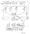
- FIG. 5 is a block diagram for an adaptive noise suppresser showing data flow in accordance with equations (1)-(14).
- the adaptive noise suppresser may be utilized for example as an adaptive line enhancer (ALE).
- ALE adaptive line enhancer
- FIG. 5 includes input 74, error output 82, filter output 84 and adder 80.
- the adaptive noise suppresser of Figure 5 is also seen to comprise a delay 102, FFT 104 and 105, IFFT 108, window 110 vector ⁇ calculating device 112, summer 114, vector multipliers 116, 118 and 120 and a projection operator 122.
- Window 110 serves to zero the first L terms of the error output as per equation (9).
- the vector ⁇ calculating device 112 determines the value of the vector ⁇ (k) in accordance with equation (14) utilizing stored values for ⁇ min and ⁇ .
- Vector multipliers 116, 118 and 120 perform the element by element, outer product vector multiplication.
- Multiplier 120 forms the weighted means for multiplying the frequency coefficients of FFT 104 by the vector weights to permit adaptive filtering using a mean square algorithm.
- the projection operator 122 serves to remove the effects of circular convolution to provide an output which corresponds to a linear convolution.
- the projection operator is defined by equation (12) and is seen to comprise IFFT 124, window 126 and FFT 128. Window 126 operates to zero the last L terms of data and is effective for removing circular convolution effects.
- the loop identified by Z ⁇ 1 in Figure 5 represents the feedback of the previous weight as called for in equation (10).
- the noise suppressed signal is taken at filter output 84.
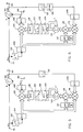
- FIG. 6 An alternate embodiment of the invention is illustrated in Figure 6 which is identical to Figure 5 with the exception of a stack 130 positioned after window 110.
- the stack is a memory store which serves to store the windowed data and to combine it with a second group of windowed stored data so that a full block of data may be fed to the FFT 106.
- the groups In combining the two groups of data, the groups are simply placed adjacent one another to produce a full block of data without the added zeros.
- equation (9) is replaced by: Stacking has been found to introduce negligible effects due to alisning. Data stacking is not necessary but will allow a more efficient operation in performing the FFT 106, thus reducing power consumption.
- Figure 7 Yet another embodiment of the invention is illustrated in Figure 7. This embodiment is similar to Figure 6 but the delayed weight sample is now taken after the projection operator 122.
- equation (10) is replaced by:
- the stack 130 is optional and may be removed to achieve a similar embodiment as in Figure 5 using equation (9).
- the delay and adaptive filters for speech processing be chosen to be equal to a pitch period which is approximately 8 ms, e.g., reference 12.
- a pitch period which is approximately 8 ms, e.g., reference 12.
- the delay of a pitch period while suitable for vowels is not suitable for fricatives or plosive sounds. Such sounds are destroyed by the large delay making it difficult to distinguish, for example, "tired” from "dired.”
- the s, sh, d, t may be largely confused and non-distinguishable.
- speech intelligibility is greatly improved by selecting the delay to be on the order of 1-3 ms and most preferably to be about 1 ms. Such selection will preserve speech intelligibility for all sounds, especially for plosive and fricative sounds.
- Another important aspect of the invention is to utilize a leak factor ⁇ as per equation (10) so as to make the filter forgetting time the same as the filter learning time. It has been noted that absent a leak factor, noise reverberation builds up at the output of the filter especially at the end of a word. This reverberation has much the same effect as a jet aircraft passing overhead, i.e., it produces a shshsh sound at the end of every word. The reverberation takes place because at the end of a word there is zero or very little energy entering a particular frequency bin. If there is no forgetting time, the filter weights are maintained and subsequent residual noise coming through the filter is amplified with the existing weights resulting in the reverberation.
- a "leak" constant ⁇ representation of the weight forgetting time is utilized as a multiplier of the weights in computing the updated weights.
- a minimum ⁇ is selected such that the updated ⁇ will be equal to the minimum ⁇ plus a calculated value of ⁇ .
- This minimum ⁇ is important to prevent an over compensation of the filter weights which would result with a zero or very little energy content within a particular frequency bin. For example, since ⁇ is selected to be inversely proportional to the power within a particular frequency bin and a zero power within a particular bin will result in an infinite choice ford ⁇ . On the next sample, however, a relatively small amplitude signal will be multiplied by the infinite (very large) ⁇ resulting in over compensation and undesirable noise.
- the frequency spectrum in these bins tends to become very noisy.
- Introduction of a minimum ⁇ however eliminates this noise background and eliminates the over compensation.
- the minimum value of ⁇ may be selected to be different for each frequency bin and may be chosen to be inversely proportional to the power spectrum of speech.
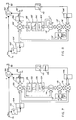
- a feedback suppression device is illustrated by the block diagram of Figure 8. It is noted that Figure 8 is similar to Figure 5 and the corresponding elements have been identified corresponding primed numbers. The formula in equations (1)-(14) also apply; however, for the frequency suppression device the output is taken from the error output 82' rather than the filter output 84'. Furthermore, delay 102' now replaces delay 102. Delay 102' is selected to filter out feedback squeal and is selected to be relatively large, as for example, on the order of 100 ms. With these modifications, the details of the filter algorithm utilized to implement Figure 8 are the same as those shown in Figure 5 with regard to noise suppression.
- the embodiment of the invention shown in Figure 9 incorporates a noise suppression device 40 and a feedback suppression device 42 into a hearing aid having a microphone 200, A/D converter 400, D/A converter 600 and output device 800.
- the hearing aid device may typically be designed utilizing a mircoprocessor or range scale integrated circuits such that the entire device may be small enough to be fitted into the ear as in present day hearing aids.
- the output device 800 may be a speaker or earphone for transmitting the final analog output of the hearing aid to the eardrum of the hearing aid user.
- the adaptive speech enhancer 100 of Figure 5 and the feedback suppression device of Figure 8 may be utilized to form the respective noise suppression device 40 and feedback suppression device 42 of Figure 10.
- noise suppression device 40 as well as feedback suppression device 42 may be implemented in the form of a program algorithm, either software or firmware stored in the memory of a microprocessor.
- the microprocessor may be a conventional single chip microprocessor or a specially designed LSI or VLSI circuit operable to perform the noise and feedback suppression as set forth herein.
- Reference to individual "devices" in reference to the functions of the noise and feedback elements is simply a term to facilitate the explanation of the individual components and does not necessarily imply that these components must appear on separate and distinct integrated circuits.
- the noise suppression device 40 and feedback suppression device 42 are arranged in series as shown in Figure 9, it is only necessary to take the output 84 of Figure 5 (the noise suppressed output) and feed it as an input signal into the input 74' of Figure 8.
- the error output 82' will then represent not only the noise suppressed output but also the feedback suppressed output as desired.
- the order of noise and feedback suppression may be reversed such that frequency suppression is performed first. In the latter case, the output 82' of Figure 8 is fed as to input 74 of Figure 5 with the output taken at output 84.
- Time-domain feedback suppression may utilize the techniques exemplified in reference 11 with the delay 102' selected as indicated above and with the output taken from the error output 82'.
- the adaptive filter would essentially be represented by the embodiment of Figure 3 utilizing tapped delay lines.
- the delay 102' in Figure 8 is important to select the delay 102' in Figure 8 to be at least greater than one phonem.
- the length is selected to be 50-150 ms so that the delay 102' should be on the order of 50 ms or greater.
- the delay should be in the range of 50-500 ms with the more preferred range of 75-125 ms.
- Most preferably the delay should be selected at approximately 100 ms.
- Typical speech phonems are stationary on the order of about 20-40 ms so that the selection of 100 ms typically ensures that the phonem (or word) in the delayed and undelayed channels are completely uncorrelated by the time they are summed in adder 80'. Feedback squeal on the other hand will still be present in both the delayed and undelayed channels so that they will be correlated and summed to zero in the adder 80' providing a feedback free signal at output 82'.
- Another important aspect of the instant invention pertaining to feedback suppression is to select the number of weights in the adaptive filter to be relatively small, namely between 16 and 32 weights and most preferably at approximately 22 weights. Such a relatively small number of weights is desirable because of the nature of the feedback tone which may center around a band of frequencies. For example, assuming that the initial frequency squeal occurs at f0, the adaptive filter basically serves as a notch filter at frequency f0 to eliminate the squeal. If the frequency contains a lot of weights and has a great deal of resolution it will specifically remove the frequency f0.
- the filter is so finely tuned that a small change in the frequency feedback typically puts the squeal outside of the filter notch and the squeal begins to appear even though at a slightly different frequency.
- a high resolution filter will then have to relearn and readjust the notch to the new feedback frequency.
- This relearning takes time, and the higher the filter resolution the longer time it takes. It is thus desirable, in accordance with the invention, to produce a broad notch filter with a relatively small number of weights. Such a design will not distinguish between small changes in the feedback frequency and will thus eliminate a broader range of feedback signals without having to readjust the filter weights for each change in environment.
- the utilization of a vector ⁇ in Figure 8 is quite important in controlling the fidelity of the frequency spectrum just as in the case of the noise suppression device of Figure 5.
- the utilization of a vector ⁇ in accordance with equations 1-14 above does not represent a LMS algorithm but is rather a mean-square algorithm in the frequency-domain. Effectively, the algorithm minimizes mean-square error concurrently within each frequency bin. The result is not necessarily the same as a minimization of the total mean-square error.
- the utilization of the vector ⁇ enables the filter to response very quickly to the feedback squeal before it in fact develops into a large enough amplitude to be notices.
- the feedback suppression device of Figure 8 may be modified in a similar manner as set forth above in connection with the noise suppression device of Figures 6 and 7.
- the invention has many applications and is not limited to a hearing aid device as described in relation to Figure 9.
- the noise suppression network set forth in Figures 4 and 8 may, for example, be utilized in all types of telecommunications systems in which it is desired to eliminate background or channel noise.
- the feedback suppression network may be utilized in loud speaker systems and all sorts of audio amplification networks.
Description
- The invention is in the field of adaptive noise suppression. More particularly, the invention is directed to a microprocessing controlled digital noise suppression device employing adaptive digital filtering techniques.
-
- 1. M. Dentino, J. McCool, and B. Widrow, "Adaptive Filtering in the Frequency Domain," Proceedings IEEE, vol. 66, pp. 1658-1659, December 1978.
- 2. Earl R. Ferrara, "Fast Implementation of LMS Adaptive Filters," IEEE Trans. ASSP, vol. ASSP-28, no. 4, pp. 474-5, August 1980.
- 3. David Mansour and A. H. Gray, Jr., "Unconstrained Frequency-Domain Adaptive Filter," IEEE Trans. ASSP, vol. ASSP-30, no. 5, pp. 726,734, October 1982.
- 4. S. Shankar Narayan, Allen M. Peterson, and Madihally J. Narasimha, "Transform Domain LMS Algorithm," IEEE Trans. ASSP, vol. ASSP-31, no. 3, pp. 609-615, June, 1983.
- 5. Gregory A. Clark, Sydney R. Parker, and Sanjit K. Mitra, "A Unified Approach to Time- and Frequency-Domain Realization of FIR Adaptive Digital Filters," IEEE Trans. ASSP, vol. ASSP-31, no. 5, pp. 1073-1083, October 1983.
- 6. D. Lynn, D. M. Chabries, and R. W. Christiansen, "Noise Reduction in Speech Using Adaptive Filtering I: Signal Processing Algorithms," 103rd ASA Conference, Chicago, Ill., April 26, 1982.
- 7. Juan Carlos Ogue, Tsuneo Saito, and Yukio Hoshiko, "A Fast Convergence Frequency Domain Adaptive Filter," IEEE Trans. ASSP, vol. ASSP-31, no. 5, pp. 1312-1314, October 1983.
- 8. Francis A. Reed and Paul L. Feintuch, "A Comparison of LMS Adaptive Cancellers Implemented in the Frequency Domain," IEEE Trans. Circuits and Systems, vol. CAS-28, no. 6, pp. 610-615, June 1981.
- 9. B. Widrow, J. R. Glover, J. M. McCool, J. Kaunitz, C. S. Williams, R. H. Hearn, J. R. Zeidler, E. Dong, and R. C. Goodlin, "Adaptive Noise Cancelling: Principles and Applications," Proceedings of the IEEE, vol. 63, no. 12, pp. 1692-1716, December 1975.
- 10. B. Widrow, "Adaptive Filters," Aspects of Network and system Theory, Edited by Kalman and DeClaris, pp. 563-587, Holt, Rinehart & Winston, Inc., N.Y. 1970.
- 11. U.S. Patent 4,238,746 to McCool et al entitled Adaptive Line Enhancer.
- 12. Marvin Sambur, "Adaptive Noise Cancelling for Speech Signals," IEEE Transaction on Acoustics, Speech and Signal Processing, vol. ASSP-26, no. 5, October 1978, pp. 419-423.
- Noise suppression devices have significant applications in the enhancement of narrowband spectral lines in a broadband noise field when there is a poor signal-to-noise ratio at the input where there is insufficient a priori information on which to design appropriate filters. The device automatically filters out the components of the signal which are uncorrelated in time and passes the correlated portions. Since the properties of the device are determined solely by the input signal statistics, the properties of the filter automatically adjust to variations in the input signal statistics to obtain the least means square (LMS) approximation to a Wiener-Hopf filter. The device will thus track slowly varying spectral lines in broadband noise.
- One application of noise suppression devices may be found, for example, in hearing aids for the hearing impaired. Present day digital filtering techniques are not effective for providing truly high fidelity frequency compensation in hearing aids and often suffer from muffled sound outputs, and intolerable noise and ringing problems.
- A further problem in the conventional design of hearing aids is the inadequate treatment of background noise. Since the vowels have the greatest energy content they are typically louder than the consonants, and a related problem with conventional hearing aid design is that the user will normally reduce the volume control to moderate the higher intensity vowel energy but, at the same time sacrifice intelligence by simultaneously reducing the intensity of the lower energy consonants. Further, hearing aids which employ automatic gain control (decreasing gain as input levels increases) have the disadvantage of decreasing the gain as a function not only of the lower frequency stronger vowel sounds contained in speech but also by the large energy, low frequency background noises. The fact that the background noise as well as vowels can have the same effect on the gain control introduces an abnormal relationship between speech sounds. Consonants, for example, are not amplified sufficiently in the present of background noises resulting in greatly reduced speech intelligence. Conventional systems may be compared with a public address system in which all sounds are amplified. To persons with normal hearing one may generally say that the louder the sound the more easily it is heard. However, in the presence of background noises, the adverse amplification of these background noises greatly mask speech intelligence.
- A particular troublesome area for the hearing impaired occurs during normal conversation in a background environment of a conference or large office. Persons with normal hearing are able to selectively listen to conversations from just one other person. The hearing impaired person has no such ability and experiences a phenomenon known as "speech babble" in which all sounds are woven into an undecipherable fabric of noise and distortion. Under these circumstances, speech itself competes with noise and the hearing impaired person is constantly burdened with the mental strain of trying to filter out the sound he or she wishes to hear. The result is poor communication, frustration and fatigue.
- Yet another performance shortcoming of the conventional hearing aid resides in the area of audio feedback. The amplified signal is literally fed back to the hearing aid input microphone and passed through the amplification system repeatedly so as to produce an extremely irritating whistling or ringing. While feedback may be controlled in most fixed listening situations, i.e., concert halls and theaters, it has not been controllable for the hearing aid user who faces an ever changing acoustic environment.
- It is an object of the invention to provide a device adapted to filter background noises from speech in real time so as to improve speech intelligence.
- Yet another object of the invention is to provide a microprocessor controlled noise and feedback suppression device employing digital filtering techniques.
A noise suppression device according to the present invention is as defined inclaim 1 and a method for noise suppression is as defined inclaim 8, respectively. - The invention may be understood in reference to the detailed description set forth below taken in conjunction with the drawings wherein:
- Figure 1 is a diagram of a prior art adaptive canceller;
- Figure 2 is a block diagram of a prior art adaptive line enhancer;
- Figure 3 is a diagram of a delay line forming part of the adaptive enhancer of Figure 2;
- Figure 4 is a time-domain representation of a digital adaptive filter with M references of length Lm;
- Figure 5 is a diagram of an adaptive line enhancer in accordance with the invention;
- Figures 6-7 are other embodiments of the adaptive line enhancer similar to that of Figure 5;
- Figure 8 is another embodiment of the invention suitable for feedback suppression and similar to that of Figure 5; and
- Figure 9 is a block diagram of noise and frequency suppressers incorporated in a hearing aid device.
- Adaptive filters are filters that adjust themselves automatically based on a given performance criteria. The most common such filter is the LMS adaptive filter.
- Figure 1 is a block diagram of a prior art
adaptive canceller 50 which has anadaptive filter 52 which adjusts itself so as to minimize the means square error between the desired input and the filter output. This filter was first proposed by Widrow et al reference (9). By analyzing the expectation of signals at various points in the structure, it can be easily shown that components of the desired input that are correlated with components of the reference input will be cancelled from the error output leaving only uncorrelated components. This structure is commonly employed in the filtering of narrow band speech corrupted by noise. Figure 1 illustrates a two microphone configuration wherein speech and noise signals are presented to the desiredinput 54, while a sample of the noise alone is presented to thereference input 56. Ideally the two noise inputs are correlated with each other while the speech and noise are uncorrelated. Thus, the noise component is removed from the signal inadder 58, leaving speech inerror output 60. Any speech signal present at thereference input 56 limits the maximum possible signal to noise gain to the inverse of the speech to noise ratio at the reference input. - In many applications, such as hearing aid applications, an independent sample of the noise is typically not available. In such cases, a one microphone configuration is employed as shown by the
adaptive enhancer 70 of Figure 2. In this configuration, anadaptive filter 72 is fed a combined speech and noise signal applied from theinput 74 through adelay 76. The delayed speech and noise signals thus serve as a reference input to theadaptive filter 72 and are fed thereto alongline 78. Thedelay 76 is chosen such that the noise components of the desired and reference inputs are uncorrelated with each other while the signal components remain correlated. To minimize the mean square error, the correlated components, in this case the speech, are cancelled inadder 80 leaving noise in theerror output 82, and speech in thefilter output 84. - The structure of the
adaptive filters - The relationship between the mean square error and the weight values is quadratic. A plot of the mean square error against a single weight yields a parabola. Plotting the mean square error against N weights in N dimensions yields a concave hyperparaboloidal surface. To minimize the mean square error, the weights are adjusted according to the negative gradient of this error surface. The weight update consists of computing an estimate of the gradient; scaling it by a scaler adaptive learning constant, µ ; and subtracting this from the previous weight value.
- Time-domain and frequency-domain adaptive filtering techniques have been utilized with varying degrees of success to filter background noise from speech. e.g., see references 1-12. Prior filtering algorithms have, however, failed to provide the desired results producing speech that sounds muffled or has a large reverberation component. These undesirable effects result from the non-periodic nature of the input signal and the utilization of the discrete FFT to perform the digital filtering. The FFT is derived from the Fourier series expansion of the signal which assumes that the input function is periodic. With this assumption, the input signal is sampled to obtain a discrete Fourier transform, the transform coefficients are then processed and the inverse discrete Fourier transform is taken on the manipulated coefficients. Ideally, one desires to obtain the same result as if one were utilizing a non-periodic transform. Dentino (reference 1) discusses adaptive filtering in the frequency-domain but fails to adequately take into effect the circular convolution introduced by the FFT. These circular or wrap-around effects may be seen, for example, in the time-domain by considering a circular convolution of an input signal which is L samples long and utilizing a filter which is M samples long. The output of the filter is the convolution sum of L + M samples. If one does a circular convolution without adding zeros prior to taking the convolution one will obtain circular or wrap-around effects which introduce harmonics of the noise which is sought to be cancelled. Moreover, the wrap-around effects are not limited solely to harmonics but may introduce sub-harmonics of the wrap-around frequency resulting from alising.
- Ferrara (reference 2) employed the FFT to obtain high speed convolution with the overlap and save technique for a block updated version of the time-domain LMS algorithm. This fast LMS algorithm required five FFT's but provided a computational savings over the time-domain implementation for moderate to very large filter lengths. The time-domain technique of Ferrara suffers from a common deficiency of all time-domain approaches in that they are too slow. Such techniques typically attempt to minimize mean-square error by taking the frequency component that has the most error and work to minimize that error first, then take the next highest error, minimizing it and so forth. When such techniques are applied to speech, the lower frequency components which have the most energy are first minimized, then the intermediate frequency components, having the intermediate energy, and finally the higher frequency components which have the least energy. However, by the time the adaptive filter treats the higher frequency components there is little or no time left. For example, time-domain filters have a response time on the order of 200-300 ms which is quite long as compared to the dynamics of speech which is in the range of 20-40 ms. As a result, in time-domain filtering the background noises which appear in the higher frequency components are not effectively filtered, a result which subjectively "muffles" the speech.
- An important part of applicant's invention is to utilize a vector variable, µ, used as an update to the filter. µ determines how fast the filter learns, the larger µ corresponding to the shorter learning time. However, in an adaptive filter, the faster the filter learns, the more error is present so that while the output signal appears at the filtered
output 84 quickly it nevertheless contains output errors similar to noise. The faster the filter adapts, the more noise is present. - Employing a vector µ, in accordance with the principles of the invention, one is able to utilize a different learning time for each frequency bin in the input spectrum. The objective is to minimize mean-square error. However, in order to preserve fidelity, the learning time constant is normalized to the power in each frequency bin. Thus, µ is selected to be inversely proportional to the power in each frequency bin. As a result, the time it takes for each frequency bin to adapt to the incoming signal is identical, that is, the filter takes the same time to learn the lower frequency as it does to learn the higher frequency components. The result is greatly improved fidelity and intelligibility since the input waveform is processed in a distortion free manner.
- Utilizing a vector µ selected specifically for each bin has the advantage of enabling separate and simultaneous mean square fits for each frequency bin wherein the computations may be performed in a parallel mode.
- Although the concept of a vector µ has been utilized by Mansour and Gray (reference 3) and by Narayan et al (reference 4) and Ogue et al (reference 7) these teachings utilize erroneous computational techniques or are adapted to the two microphone input such as shown in the adaptive canceller of Figure 1.
- An illustration of the noise cancellation algorithm employed in the adaptive filter enhancer is found in reference to Figures 4-5.
- The mathematical nomenclature is introduced in reference to the classical adaptive noise cancellation problem shown in Figure 4, and may also be found from the literature references 1-12.
- Defining the primary input as d(n), the filter output y(n) and the reference inputs as xm(n), with n the sample index, the desired and reference inputs and the filter output may be divided into blocks with index k and represented by the vectors

as follows
where
m=0,1,2,...,M-1=reference channel number
Lm= 2αm
L = 2α
and
α,αm = integers specifying the block lengths.
Transforms may be obtained using the matrix FFTL as.
and
Further, let
represent the FFT of the (k-1)st and kth consecutive blocks of the mth reference given as
and the output of the mth filter
where the notation A Ⓧ B denotes the element by element multiplication of the two vectors A and B which results in a vector. The sum of the outputs from all filters of various lengths, Lm, blocked to L output samples is
and
Similarly, the error blocked to L samples becomes
Padding with zeroes and transforming,
- where the definition

will be used. The weight update equation using the method of steepest descents becomes
where the symbol * denotes conjugation, ρ specifies the rate of leakage, and the quantity µ is
The fact that the weights have been obtained by circular convolution is denoted by. To force the resultant output

to correspond to a linear convolution, the frequency-domain weight vector is obtained as
where
is the Lmxlm identity matrix. The truncation of the weight vector in equation (12) insures that the last half of a time-domain representation of the weights is identically zero. - The weight vector corresponding to the mth reference,

is updated once each Lm samples and the output vector
is obtained from equation (5). y(n) in Figure 5 represents one of the elements of the vector
- The fast LMS (FLMS) algorithm (reference 2) is an implementation of the time-domain LMS algorithm with the constraint that the filter weights are updated once for each block of input data and employs the overlap and save technique for fast convolution. If the vector µ of equation (11) is replaced with a scalar times the identity matrix (i.e. µ = µI), the truncation operation of equation (12) effects only the second term of the expression for

In this case the order of the µ scaling and truncation operation are rearranged. With this ordering of the operations and the substitution L=Lm, the frequency-domain algorithm yields the FLMS algorithm. - The addition of the vector feedback coefficients, µ , in the general algorithm allows faster convergence for the cases where the reference input autocorrelation matrix exhibits large eigenvalue disparity. One technique for selecting the values of µ, which make up µ is described in (reference 7):

A preferred embodiment for selecting µ(k) which is robust in rapidly changing, non-stationary problems is to select an µmin which represents a bound on the minimum values that µ will take on in each frequency bin and average exponentially as
The value for β may be chosen to achieve an exponentially averaged time constant for µ of approximately [1-β]⁻¹. The choice of λ controls the rate of convergence for those frequency bins where λ times the respective eigenvalue of
are much greater than the same component of µmin. This implementation of µ(k) in equation (14) tends to normalize the convergence rate in each frequency bin to a common time constant. - Clark et al (reference 5) have already noted the similarity between the Dentino and UFLMS algorithms and the unified block LMS algorithm. In (reference 5) however, the derivation showing the equivalence of the Dentino (or frequency-domain adaptive filter, FDAF) and the block LMS is incorrect in that the error used in equation (39) for the FDAF is not the same as the error used in equation (32) for the time-domain block adaptive filter in that paper. Specifically, circular convolution results are introduced into the gradient estimate.
- In the Dentino algorithm (reference 1), the blocking is not described and the elimination of the blocking is tantamount to the removal of the windows (or equivalently zero padding) in equations (9) and (12). Reed (reference 8) compared the Dentino algorithm with the LMS time-domain algorithm and noted that under appropriate conditions the block processing effects could be minimized. Further, use of the Dentino algorithm in the implementation of an adaptive line enhancer (reference 9) with reference delays less than the block length allows for a minimum mean-square error solution due to circular convolution, thereby changing the effect of the time-domain delay as a constraint.
- The UFLMS (reference 3) and the general algorithm may be related by insuring that the input signal meets certain requirements. Specifically, by applying the constraint that the system to be modelled is an FIR filter of order less than or equal to the order of the adaptive filter, the projection operation in equation (12) may be eliminated and the two algorithms become equivalent.
- The transform domain algorithm proposed by Narayan (reference 4) blocks the data so that only one output point is obtained with each filter operation. The inverse transform is then imbedded in the filter coefficients and circular convolution effects are avoided; however, an increased computational burden is imposed. A similar result may be obtained by the present frequency-domain algorithm if one eliminates the zero-padding in equations (9) and (12) and only a single output point is extracted from each block computation and each block of
length 2Lm overlaps the previous block by all but one sample. - The algorithm in equations (1)-(14) allows an ALE to be implemented which incorporates a vector µ and preserves the constraint intended by the delay in the reference channel. Additionally, the value of µ may be allowed to vary in the case of non-stationary inputs. Such a feature becomes important in speech modelling, for example, where the speech spectrum is not white and inputs are non-stationary.
- In the application of the algorithm to the processing of speech signals, three considerations are of special importance:
- 1. the rate of learning may be selected by choosing β in equation (14) and the rate should be set equal to the "forgetting" rate determined by ρ in equation (10).
- 2. the amount of delay in the adaptive line enhancer of Figure 5 should be set in the range of 1-3 ms and most preferably at about 1 ms.
- 3. the selection of µmin should be chosen to vary inversly as the energy in the speech spectrum to be processed.
- The formulation of the general frequency-domain algorithm in equations (1)-(14) allows the implementation of these features.
- Figure 5 is a block diagram for an adaptive noise suppresser showing data flow in accordance with equations (1)-(14). The adaptive noise suppresser may be utilized for example as an adaptive line enhancer (ALE). Features of Figure 5 in common with Figure 2 have been similarly labeled, and include
input 74,error output 82,filter output 84 andadder 80. The adaptive noise suppresser of Figure 5 is also seen to comprise adelay 102,FFT 104 and 105,IFFT 108,window 110 vectorµ calculating device 112,summer 114,vector multipliers projection operator 122.Window 110 serves to zero the first L terms of the error output as per equation (9). The vector µ calculatingdevice 112 determines the value of the vector µ(k) in accordance with equation (14) utilizing stored values for µmin and β .Vector multipliers Multiplier 120 forms the weighted means for multiplying the frequency coefficients ofFFT 104 by the vector weights to permit adaptive filtering using a mean square algorithm. Theprojection operator 122 serves to remove the effects of circular convolution to provide an output which corresponds to a linear convolution. The projection operator is defined by equation (12) and is seen to compriseIFFT 124,window 126 andFFT 128.Window 126 operates to zero the last L terms of data and is effective for removing circular convolution effects. - The loop identified by Z⁻¹ in Figure 5 represents the feedback of the previous weight as called for in equation (10).
- The noise suppressed signal is taken at
filter output 84. - An alternate embodiment of the invention is illustrated in Figure 6 which is identical to Figure 5 with the exception of a
stack 130 positioned afterwindow 110. The stack is a memory store which serves to store the windowed data and to combine it with a second group of windowed stored data so that a full block of data may be fed to theFFT 106. In combining the two groups of data, the groups are simply placed adjacent one another to produce a full block of data without the added zeros. In so doing, equation (9) is replaced by:
Stacking has been found to introduce negligible effects due to alisning. Data stacking is not necessary but will allow a more efficient operation in performing theFFT 106, thus reducing power consumption. - Yet another embodiment of the invention is illustrated in Figure 7. This embodiment is similar to Figure 6 but the delayed weight sample is now taken after the
projection operator 122. In this case, equation (10) is replaced by:
In Figure 7, thestack 130 is optional and may be removed to achieve a similar embodiment as in Figure 5 using equation (9). - In implementing the invention in accordance with the block diagram of Figures 5-7 care must be taken in selecting the
delay 102. Most noise is impulsive in nature resembling a click or tap. This impulsive noise is very short lived, and after passing through even ashort delay 102 will be uncorrelated with the desired (undelayed) signal inputted intoadder 80. That is, the impulsive noise in the undelayed channel will already have passed through theadder 80 by the time delayed impulse arrives thereto. Speech, however, has a great deal of redundancy and is much longer lived than impulsive noise. As a result, delayed speech arriving at theadder 80 is still correlated with the undelayed speech input. - An important aspect of the invention is the proper selection of the
delay 102. It has been suggested, for example, that the delay and adaptive filters for speech processing be chosen to be equal to a pitch period which is approximately 8 ms, e.g., reference 12. However, in accordance with the invention it has been found that the delay of a pitch period, while suitable for vowels is not suitable for fricatives or plosive sounds. Such sounds are destroyed by the large delay making it difficult to distinguish, for example, "tired" from "dired." Thus, the s, sh, d, t, may be largely confused and non-distinguishable. In accordance with the invention speech intelligibility is greatly improved by selecting the delay to be on the order of 1-3 ms and most preferably to be about 1 ms. Such selection will preserve speech intelligibility for all sounds, especially for plosive and fricative sounds. - Another important aspect of the invention is to utilize a leak factor ρ as per equation (10) so as to make the filter forgetting time the same as the filter learning time. It has been noted that absent a leak factor, noise reverberation builds up at the output of the filter especially at the end of a word. This reverberation has much the same effect as a jet aircraft passing overhead, i.e., it produces a shshsh sound at the end of every word. The reverberation takes place because at the end of a word there is zero or very little energy entering a particular frequency bin. If there is no forgetting time, the filter weights are maintained and subsequent residual noise coming through the filter is amplified with the existing weights resulting in the reverberation. In accordance with the invention a "leak" constant ρ representation of the weight forgetting time is utilized as a multiplier of the weights in computing the updated weights. Further, a minimum µ is selected such that the updated µ will be equal to the minimum µ plus a calculated value of µ . This minimum µ is important to prevent an over compensation of the filter weights which would result with a zero or very little energy content within a particular frequency bin. For example, since µ is selected to be inversely proportional to the power within a particular frequency bin and a zero power within a particular bin will result in an infinite choice ford µ . On the next sample, however, a relatively small amplitude signal will be multiplied by the infinite (very large) µ resulting in over compensation and undesirable noise. In bins where there is very little speech for any length of time the frequency spectrum in these bins tends to become very noisy. Introduction of a minimum µ however eliminates this noise background and eliminates the over compensation. Further, the minimum value of µ may be selected to be different for each frequency bin and may be chosen to be inversely proportional to the power spectrum of speech.
- A feedback suppression device is illustrated by the block diagram of Figure 8. It is noted that Figure 8 is similar to Figure 5 and the corresponding elements have been identified corresponding primed numbers. The formula in equations (1)-(14) also apply; however, for the frequency suppression device the output is taken from the error output 82' rather than the filter output 84'. Furthermore, delay 102' now replaces
delay 102. Delay 102' is selected to filter out feedback squeal and is selected to be relatively large, as for example, on the order of 100 ms. With these modifications, the details of the filter algorithm utilized to implement Figure 8 are the same as those shown in Figure 5 with regard to noise suppression. - The embodiment of the invention shown in Figure 9 incorporates a
noise suppression device 40 and afeedback suppression device 42 into a hearing aid having a microphone 200, A/D converter 400, D/A converter 600 and output device 800. The hearing aid device may typically be designed utilizing a mircoprocessor or range scale integrated circuits such that the entire device may be small enough to be fitted into the ear as in present day hearing aids. The output device 800 may be a speaker or earphone for transmitting the final analog output of the hearing aid to the eardrum of the hearing aid user. The adaptive speech enhancer 100 of Figure 5 and the feedback suppression device of Figure 8 may be utilized to form the respectivenoise suppression device 40 andfeedback suppression device 42 of Figure 10. It is understood that the embodiment of Figure 9 may be utilized with only one or both of these noise and feedback suppression devices as they operate independently of one another. Moreover, it is understood thatnoise suppression device 40 as well asfeedback suppression device 42 may be implemented in the form of a program algorithm, either software or firmware stored in the memory of a microprocessor. Moreover, the microprocessor may be a conventional single chip microprocessor or a specially designed LSI or VLSI circuit operable to perform the noise and feedback suppression as set forth herein. Reference to individual "devices" in reference to the functions of the noise and feedback elements is simply a term to facilitate the explanation of the individual components and does not necessarily imply that these components must appear on separate and distinct integrated circuits. - When the
noise suppression device 40 andfeedback suppression device 42 are arranged in series as shown in Figure 9, it is only necessary to take theoutput 84 of Figure 5 (the noise suppressed output) and feed it as an input signal into the input 74' of Figure 8. The error output 82' will then represent not only the noise suppressed output but also the feedback suppressed output as desired. Alternately, the order of noise and feedback suppression may be reversed such that frequency suppression is performed first. In the latter case, the output 82' of Figure 8 is fed as to input 74 of Figure 5 with the output taken atoutput 84. - If feedback suppression is implemented in the frequency-domain as shown in Figure 8, and is further utilized with the noise suppression device of Figure 5, it is not necessary to take the
IFFT 108 in Figure 5 and then take the FFT 104' in Figure 8. Rather, some savings may be made by taking the output of themultiplier 120 of Figure 5, and feeding it directly to the input 74' of Figure 8. The FFT 104' of Figure 8 will then be eliminated thus permitting computational savings in taking the inverse and its transform to achieve the noise and feedback suppression. - It is also noted, that the feedback suppression may be implemented in the time-domain as long as the delay is selected to be equal to or greater than 100 ms. Time-domain feedback suppression may utilize the techniques exemplified in reference 11 with the delay 102' selected as indicated above and with the output taken from the error output 82'. In this case, the adaptive filter would essentially be represented by the embodiment of Figure 3 utilizing tapped delay lines.
- It is important to select the delay 102' in Figure 8 to be at least greater than one phonem. Typically the length is selected to be 50-150 ms so that the delay 102' should be on the order of 50 ms or greater. Preferably, the delay should be in the range of 50-500 ms with the more preferred range of 75-125 ms. Most preferably the delay should be selected at approximately 100 ms. Typical speech phonems are stationary on the order of about 20-40 ms so that the selection of 100 ms typically ensures that the phonem (or word) in the delayed and undelayed channels are completely uncorrelated by the time they are summed in adder 80'. Feedback squeal on the other hand will still be present in both the delayed and undelayed channels so that they will be correlated and summed to zero in the adder 80' providing a feedback free signal at output 82'.
- Another important aspect of the instant invention pertaining to feedback suppression is to select the number of weights in the adaptive filter to be relatively small, namely between 16 and 32 weights and most preferably at approximately 22 weights. Such a relatively small number of weights is desirable because of the nature of the feedback tone which may center around a band of frequencies. For example, assuming that the initial frequency squeal occurs at f₀, the adaptive filter basically serves as a notch filter at frequency f₀ to eliminate the squeal. If the frequency contains a lot of weights and has a great deal of resolution it will specifically remove the frequency f₀. However, if the environment of the hearing aid changes, as for example by the user placing an object next to the ear, the filter is so finely tuned that a small change in the frequency feedback typically puts the squeal outside of the filter notch and the squeal begins to appear even though at a slightly different frequency. A high resolution filter will then have to relearn and readjust the notch to the new feedback frequency. This relearning takes time, and the higher the filter resolution the longer time it takes. It is thus desirable, in accordance with the invention, to produce a broad notch filter with a relatively small number of weights. Such a design will not distinguish between small changes in the feedback frequency and will thus eliminate a broader range of feedback signals without having to readjust the filter weights for each change in environment.
- The utilization of a vector µ in Figure 8 is quite important in controlling the fidelity of the frequency spectrum just as in the case of the noise suppression device of Figure 5. The utilization of a vector µ in accordance with equations 1-14 above does not represent a LMS algorithm but is rather a mean-square algorithm in the frequency-domain. Effectively, the algorithm minimizes mean-square error concurrently within each frequency bin. The result is not necessarily the same as a minimization of the total mean-square error. For the feedback application the utilization of the vector µ enables the filter to response very quickly to the feedback squeal before it in fact develops into a large enough amplitude to be notices. Thus, rather than utilizing a scaler µ and treating the total frequency spectrum by concentrating on only the higher energy components first and then treating the lower energy components etc. one is able to treat all frequency bins at the same time to minimize error within each bin concurrently. The would be feedback squeal is filtered at its very inception so that it never really develops into any noticeable squeal. As in noise suppression, µ is selected such that the learning time for all frequency bins is identical.
- The feedback suppression device of Figure 8 may be modified in a similar manner as set forth above in connection with the noise suppression device of Figures 6 and 7.
- It is understood that the arrangement shown in Figure 9 for the hearing aid device may take many forms and does not have to be embodied in the exact forms shown. For example,
feedback suppression device 42 may preceed thenoise suppression device 40. - The invention has many applications and is not limited to a hearing aid device as described in relation to Figure 9. In particular, the noise suppression network set forth in Figures 4 and 8 may, for example, be utilized in all types of telecommunications systems in which it is desired to eliminate background or channel noise. Further, the feedback suppression network may be utilized in loud speaker systems and all sorts of audio amplification networks.
- While the invention has been described in reference to various embodiments, it is understood that many modifications and improvements may be made by those skilled in the art without departing from the scope of the claims.
Claims (8)
- A noise suppression device for providing a noise filtered speech signal comprising:
means (102) for delaying an input signal X by a fixed delay Δ, Δ being on the order of less than a pitch period;
means (104) for transforming the delayed signal into the frequency domain;
weighted means, having weights and having inputs connected to the transforming means (104), for adaptably filtering the delayed, transformed signal using a mean square algorithm in the frequency domain;
means (108) for transforming the output of the weighted means into a time domain signal comprising the noise filtered speech signal Y;
means (80), having as inputs the signals X and Y for subtracting the signal Y from X, the output of the subtracting means being a noise error signal ε ;
means (106) for transforming the noise error signal into the frequency domain to produce a transformed error signals;
means for multiplying the transformed noise error signals by a vector gain µ;
projection operator means receiving the output of the multiplying means for removing the effects of circular convolution, the output of the projection operator means (122) being fed back to the weighted means to cause the weights of the weighted means to be readjusted in a manner to minimize the difference between the signal X and the signal Y, thereby minimizing the error signal and producing noise suppressed speech in the filtered speech signal Y,
wherein the vector gain µ is selected in each frequency bin of the frequency spectrum to be inversely proportional to the power in the frequency spectrum, whereby spectrum fidelity is preserved, and
wherein said signals X, Y, and ε comprise a plurality of digital signals representing a sampled group of speech and noise data and said device further comprises means (110)for zeroing the last half of the ε data signals in the sampled group of data for providing zeroed ε data signals to said noise error signal transforming means and wherein said transforming means receive said zeroed ε data signals for transforming same into the frequency domain. - A noise suppression device as recited in Claim 1, wherein Δ is on the order of 1-3 ms.
- A noise suppression device as recited in Claim 2, wherein Δ is on the order of 1 ms.
- A noise suppression device as recited in Claim 1 further comprising means for combining a second group of zeroed ε data signals at the end of a first group of zeroed ε data signals for producing a full group of ε data signals for providing same to said noise error signal transforming means and wherein said transforming means receives said full group of ε data signals for transforming same into the frequency domain.
- A noise suppression device as recited in claim 1, further comprising means for multiplying said weights by a leak factor ρ so as to decrease the value of said weights in inverse proportion to the power in the frequency spectrum.
- A method of noise suppression for providing a noise filtered speech signal comprising the steps of:a) delaying an input signal X by a fixed delay Δ, Δ being on the order of less than a pitch period;b) transforming the delayed signal into the frequency domain;c) adaptably filtering the delayed, transformed signal using a plurality of weights and a mean square algorithm in the frequency domain to provide a filtered output signal;d) transforming the filtered output signals into a time domain signal comprising the noise filtered speech signal Y;e) subtracting the signal Y from X for obtaining a noise error signal ε;f) transforming the noise error signal into the frequency domain to produce a transformed error signals;g) multiplying the transformed noise error signals by a vector gain µ;h) removing the effects of circular convolution from the multiplied noise error signal; andi) feeding back the results of step h) to adjust the weights in the mean square algorithm in a manner to minimize the difference between the signal X and the signal Y, thereby minimizing the error signal ε and producing noise suppressed speech in the noise filtered speech signal Y,j) selecting the vector gain µ in each frequency bin of the frequency spectrum to be inversely proportional to the power in the frequency spectrum, whereby spectrum fidelity is reserved, and wherein said signals X, Y, and ε comprise a plurality of digital signals representing a sampled group or speech and noise data and, after said subtracting step e), said method further comprises the step of zeroing the first half of the ε data signals in the sampled group of data for providing zeroed ε data signals for transforming in accordance with step f).
- The method of Claim 6, wherein the step of delaying the input signal comprises delaying the input signal on the order of 50-500 ms.
- Use of the device and for method of any of the preceding claims in a hearing aid.
Applications Claiming Priority (2)
| Application Number | Priority Date | Filing Date | Title |
|---|---|---|---|
| US785999 | 1985-10-10 | ||
| US06/785,999 US4658426A (en) | 1985-10-10 | 1985-10-10 | Adaptive noise suppressor |
Publications (2)
| Publication Number | Publication Date |
|---|---|
| EP0220563A1 EP0220563A1 (en) | 1987-05-06 |
| EP0220563B1 true EP0220563B1 (en) | 1992-05-27 |
Family
ID=25137296
Family Applications (1)
| Application Number | Title | Priority Date | Filing Date |
|---|---|---|---|
| EP86113983A Expired - Lifetime EP0220563B1 (en) | 1985-10-10 | 1986-10-09 | Adaptive noise suppressor |
Country Status (7)
| Country | Link |
|---|---|
| US (1) | US4658426A (en) |
| EP (1) | EP0220563B1 (en) |
| JP (1) | JPS62155606A (en) |
| AU (1) | AU582018B2 (en) |
| CA (1) | CA1250348A (en) |
| DE (1) | DE3685474D1 (en) |
| DK (1) | DK485986A (en) |
Families Citing this family (143)
| Publication number | Priority date | Publication date | Assignee | Title |
|---|---|---|---|---|
| JPS62135020A (en) * | 1985-12-06 | 1987-06-18 | Nec Corp | Noise erasing device |
| US5029217A (en) * | 1986-01-21 | 1991-07-02 | Harold Antin | Digital hearing enhancement apparatus |
| US4939685A (en) * | 1986-06-05 | 1990-07-03 | Hughes Aircraft Company | Normalized frequency domain LMS adaptive filter |
| US4926488A (en) * | 1987-07-09 | 1990-05-15 | International Business Machines Corporation | Normalization of speech by adaptive labelling |
| US5157596A (en) * | 1987-07-17 | 1992-10-20 | Hughes Aircraft Company | Adaptive noise cancellation in a closed loop control system |
| GB8801014D0 (en) * | 1988-01-18 | 1988-02-17 | British Telecomm | Noise reduction |
| US5111419A (en) * | 1988-03-23 | 1992-05-05 | Central Institute For The Deaf | Electronic filters, signal conversion apparatus, hearing aids and methods |
| US5225836A (en) * | 1988-03-23 | 1993-07-06 | Central Institute For The Deaf | Electronic filters, repeated signal charge conversion apparatus, hearing aids and methods |
| US5016280A (en) * | 1988-03-23 | 1991-05-14 | Central Institute For The Deaf | Electronic filters, hearing aids and methods |
| US5046103A (en) * | 1988-06-07 | 1991-09-03 | Applied Acoustic Research, Inc. | Noise reducing system for voice microphones |
| US5091952A (en) * | 1988-11-10 | 1992-02-25 | Wisconsin Alumni Research Foundation | Feedback suppression in digital signal processing hearing aids |
| US4893082A (en) * | 1989-02-13 | 1990-01-09 | Letcher Iii John H | Noise suppression in magnetic resonance imaging |
| CA2015253A1 (en) * | 1989-05-25 | 1990-11-25 | Robert T. Beierle | Adaptive analysis apparatus |
| US5126681A (en) * | 1989-10-16 | 1992-06-30 | Noise Cancellation Technologies, Inc. | In-wire selective active cancellation system |
| US5097510A (en) * | 1989-11-07 | 1992-03-17 | Gs Systems, Inc. | Artificial intelligence pattern-recognition-based noise reduction system for speech processing |
| US5243661A (en) * | 1990-04-09 | 1993-09-07 | Sony Corporation | Microphone apparatus |
| DE69118486T2 (en) * | 1990-06-13 | 1996-12-19 | Sabine Musical Mfg Co Inc | METHOD AND DEVICE FOR ADAPTIVELY FILTERING AN AUDIORESONANCE FREQUENCY |
| CA2054606C (en) * | 1990-11-01 | 1994-06-28 | Akihiko Sugiyama | Tap-weight adaptation control using stepsize inversely variable with signal power level |
| US5263019A (en) * | 1991-01-04 | 1993-11-16 | Picturetel Corporation | Method and apparatus for estimating the level of acoustic feedback between a loudspeaker and microphone |
| US5305307A (en) * | 1991-01-04 | 1994-04-19 | Picturetel Corporation | Adaptive acoustic echo canceller having means for reducing or eliminating echo in a plurality of signal bandwidths |
| US5309378A (en) * | 1991-11-18 | 1994-05-03 | Hughes Aircraft Company | Multi-channel adaptive canceler |
| US5412735A (en) * | 1992-02-27 | 1995-05-02 | Central Institute For The Deaf | Adaptive noise reduction circuit for a sound reproduction system |
| US5402496A (en) * | 1992-07-13 | 1995-03-28 | Minnesota Mining And Manufacturing Company | Auditory prosthesis, noise suppression apparatus and feedback suppression apparatus having focused adaptive filtering |
| US6563931B1 (en) * | 1992-07-29 | 2003-05-13 | K/S Himpp | Auditory prosthesis for adaptively filtering selected auditory component by user activation and method for doing same |
| US5396414A (en) * | 1992-09-25 | 1995-03-07 | Hughes Aircraft Company | Adaptive noise cancellation |
| US5355418A (en) * | 1992-10-07 | 1994-10-11 | Westinghouse Electric Corporation | Frequency selective sound blocking system for hearing protection |
| US5416847A (en) * | 1993-02-12 | 1995-05-16 | The Walt Disney Company | Multi-band, digital audio noise filter |
| US5353348A (en) * | 1993-05-14 | 1994-10-04 | Jrc International, Inc. | Double echo cancelling system |
| EP0707763B1 (en) * | 1993-07-07 | 2001-08-29 | Picturetel Corporation | Reduction of background noise for speech enhancement |
| DE4330243A1 (en) * | 1993-09-07 | 1995-03-09 | Philips Patentverwaltung | Speech processing facility |
| EP0585976A3 (en) * | 1993-11-10 | 1994-06-01 | Phonak Ag | Hearing aid with cancellation of acoustic feedback |
| JP3235925B2 (en) * | 1993-11-19 | 2001-12-04 | 松下電器産業株式会社 | Howling suppression device |
| US5581620A (en) * | 1994-04-21 | 1996-12-03 | Brown University Research Foundation | Methods and apparatus for adaptive beamforming |
| US6020782A (en) * | 1994-05-25 | 2000-02-01 | The United States Of America As Represented By The Secretary Of The Navy | Noise assisted signal processor with nonlinearly coupled arrays of nonlinear dynamic elements |
| DE4420894C2 (en) * | 1994-06-15 | 1997-01-23 | Daimler Benz Ag | Method of reducing speech signal interference |
| US6072885A (en) * | 1994-07-08 | 2000-06-06 | Sonic Innovations, Inc. | Hearing aid device incorporating signal processing techniques |
| US5500902A (en) * | 1994-07-08 | 1996-03-19 | Stockham, Jr.; Thomas G. | Hearing aid device incorporating signal processing techniques |
| US8085959B2 (en) * | 1994-07-08 | 2011-12-27 | Brigham Young University | Hearing compensation system incorporating signal processing techniques |
| US5577116A (en) * | 1994-09-16 | 1996-11-19 | North Carolina State University | Apparatus and method for echo characterization of a communication channel |
| US5526426A (en) * | 1994-11-08 | 1996-06-11 | Signalworks | System and method for an efficiently constrained frequency-domain adaptive filter |
| US5978783A (en) * | 1995-01-10 | 1999-11-02 | Lucent Technologies Inc. | Feedback control system for telecommunications systems |
| JP2760373B2 (en) * | 1995-03-03 | 1998-05-28 | 日本電気株式会社 | Noise canceller |
| US5612978A (en) * | 1995-05-30 | 1997-03-18 | Motorola, Inc. | Method and apparatus for real-time adaptive interference cancellation in dynamic environments |
| JP2685031B2 (en) * | 1995-06-30 | 1997-12-03 | 日本電気株式会社 | Noise cancellation method and noise cancellation device |
| FR2738692B1 (en) * | 1995-09-08 | 1997-10-31 | France Telecom | ADAPTIVE DIGITAL FILTERING METHOD IN THE FREQUENTIAL FIELD |
| US5737433A (en) * | 1996-01-16 | 1998-04-07 | Gardner; William A. | Sound environment control apparatus |
| US5848163A (en) * | 1996-02-02 | 1998-12-08 | International Business Machines Corporation | Method and apparatus for suppressing background music or noise from the speech input of a speech recognizer |
| JP2882364B2 (en) * | 1996-06-14 | 1999-04-12 | 日本電気株式会社 | Noise cancellation method and noise cancellation device |
| US5825898A (en) * | 1996-06-27 | 1998-10-20 | Lamar Signal Processing Ltd. | System and method for adaptive interference cancelling |
| US5742694A (en) * | 1996-07-12 | 1998-04-21 | Eatwell; Graham P. | Noise reduction filter |
| US5963899A (en) * | 1996-08-07 | 1999-10-05 | U S West, Inc. | Method and system for region based filtering of speech |
| US6098038A (en) * | 1996-09-27 | 2000-08-01 | Oregon Graduate Institute Of Science & Technology | Method and system for adaptive speech enhancement using frequency specific signal-to-noise ratio estimates |
| JP3556419B2 (en) * | 1996-12-09 | 2004-08-18 | 株式会社東芝 | Portable wireless telephone |
| US6178248B1 (en) | 1997-04-14 | 2001-01-23 | Andrea Electronics Corporation | Dual-processing interference cancelling system and method |
| AU764316C (en) * | 1997-04-16 | 2004-06-24 | Emma Mixed Signal C.V. | Apparatus for noise reduction, particulary in hearing aids |
| CA2286268C (en) | 1997-04-16 | 2005-01-04 | Dspfactory Ltd. | Method and apparatus for noise reduction, particularly in hearing aids |
| US5978489A (en) * | 1997-05-05 | 1999-11-02 | Oregon Graduate Institute Of Science And Technology | Multi-actuator system for active sound and vibration cancellation |
| US6122610A (en) * | 1998-09-23 | 2000-09-19 | Verance Corporation | Noise suppression for low bitrate speech coder |
| CA2358203A1 (en) | 1999-01-07 | 2000-07-13 | Tellabs Operations, Inc. | Method and apparatus for adaptively suppressing noise |
| US6363345B1 (en) | 1999-02-18 | 2002-03-26 | Andrea Electronics Corporation | System, method and apparatus for cancelling noise |
| US6408318B1 (en) | 1999-04-05 | 2002-06-18 | Xiaoling Fang | Multiple stage decimation filter |
| US6507623B1 (en) * | 1999-04-12 | 2003-01-14 | Telefonaktiebolaget Lm Ericsson (Publ) | Signal noise reduction by time-domain spectral subtraction |
| US7146013B1 (en) * | 1999-04-28 | 2006-12-05 | Alpine Electronics, Inc. | Microphone system |
| ATE339865T1 (en) | 1999-07-19 | 2006-10-15 | Oticon As | FEEDBACK SUPPRESSION USING BANDWIDTH DETECTION |
| EP1081985A3 (en) * | 1999-09-01 | 2006-03-22 | Northrop Grumman Corporation | Microphone array processing system for noisy multipath environments |
| SE514875C2 (en) * | 1999-09-07 | 2001-05-07 | Ericsson Telefon Ab L M | Method and apparatus for constructing digital filters |
| US6480610B1 (en) | 1999-09-21 | 2002-11-12 | Sonic Innovations, Inc. | Subband acoustic feedback cancellation in hearing aids |
| US6594367B1 (en) | 1999-10-25 | 2003-07-15 | Andrea Electronics Corporation | Super directional beamforming design and implementation |
| US6757395B1 (en) | 2000-01-12 | 2004-06-29 | Sonic Innovations, Inc. | Noise reduction apparatus and method |
| US6766292B1 (en) * | 2000-03-28 | 2004-07-20 | Tellabs Operations, Inc. | Relative noise ratio weighting techniques for adaptive noise cancellation |
| AU4323800A (en) | 2000-05-06 | 2001-11-20 | Nanyang Technological University | System for noise suppression, transceiver and method for noise suppression |
| EP1314246A1 (en) * | 2000-08-21 | 2003-05-28 | Koninklijke Philips Electronics N.V. | Partioned block frequency domain adaptive filter |
| JP2004507923A (en) * | 2000-08-21 | 2004-03-11 | コーニンクレッカ フィリップス エレクトロニクス エヌ ヴィ | Divided block frequency domain adaptive filter |
| US7613529B1 (en) * | 2000-09-09 | 2009-11-03 | Harman International Industries, Limited | System for eliminating acoustic feedback |
| US6963649B2 (en) * | 2000-10-24 | 2005-11-08 | Adaptive Technologies, Inc. | Noise cancelling microphone |
| EP1211671A3 (en) * | 2000-11-16 | 2003-09-10 | Alst Innovation Technologies | Automatic gain control with noise suppression |
| US6664460B1 (en) | 2001-01-05 | 2003-12-16 | Harman International Industries, Incorporated | System for customizing musical effects using digital signal processing techniques |
| DE10110258C1 (en) * | 2001-03-02 | 2002-08-29 | Siemens Audiologische Technik | Method for operating a hearing aid or hearing aid system and hearing aid or hearing aid system |
| GB0116493D0 (en) | 2001-07-06 | 2001-08-29 | Koninkl Philips Electronics Nv | Receiver having an adaptive filter and method of optimising the filter |
| CA2357200C (en) * | 2001-09-07 | 2010-05-04 | Dspfactory Ltd. | Listening device |
| US6694029B2 (en) * | 2001-09-14 | 2004-02-17 | Fender Musical Instruments Corporation | Unobtrusive removal of periodic noise |
| US7177614B2 (en) * | 2002-01-02 | 2007-02-13 | Sirf Technology, Inc. | Narrowband noise mitigation in location-determining signal processing |
| WO2003079721A1 (en) * | 2002-03-13 | 2003-09-25 | Harman International Industries, Incorporated | Audio feedback processing system |
| JP2004061617A (en) * | 2002-07-25 | 2004-02-26 | Fujitsu Ltd | Received speech processing apparatus |
| US7725314B2 (en) * | 2004-02-16 | 2010-05-25 | Microsoft Corporation | Method and apparatus for constructing a speech filter using estimates of clean speech and noise |
| US7386142B2 (en) | 2004-05-27 | 2008-06-10 | Starkey Laboratories, Inc. | Method and apparatus for a hearing assistance system with adaptive bulk delay |
| US7660340B2 (en) * | 2004-06-22 | 2010-02-09 | Alcatel-Lucent Usa Inc. | Method of receiver processing of CDMA signals in a CDMA system |
| US20060133621A1 (en) * | 2004-12-22 | 2006-06-22 | Broadcom Corporation | Wireless telephone having multiple microphones |
| US7983720B2 (en) * | 2004-12-22 | 2011-07-19 | Broadcom Corporation | Wireless telephone with adaptive microphone array |
| US20060147063A1 (en) * | 2004-12-22 | 2006-07-06 | Broadcom Corporation | Echo cancellation in telephones with multiple microphones |
| US8509703B2 (en) * | 2004-12-22 | 2013-08-13 | Broadcom Corporation | Wireless telephone with multiple microphones and multiple description transmission |
| US20070116300A1 (en) * | 2004-12-22 | 2007-05-24 | Broadcom Corporation | Channel decoding for wireless telephones with multiple microphones and multiple description transmission |
| DE102005039621A1 (en) * | 2005-08-19 | 2007-03-01 | Micronas Gmbh | Method and apparatus for the adaptive reduction of noise and background signals in a speech processing system |
| CA2624629A1 (en) * | 2005-10-31 | 2007-05-10 | Telefonaktiebolaget L M Ericsson (Publ) | Reduction of digital filter delay |
| US8345890B2 (en) * | 2006-01-05 | 2013-01-01 | Audience, Inc. | System and method for utilizing inter-microphone level differences for speech enhancement |
| US8194880B2 (en) * | 2006-01-30 | 2012-06-05 | Audience, Inc. | System and method for utilizing omni-directional microphones for speech enhancement |
| US8744844B2 (en) * | 2007-07-06 | 2014-06-03 | Audience, Inc. | System and method for adaptive intelligent noise suppression |
| US8204252B1 (en) | 2006-10-10 | 2012-06-19 | Audience, Inc. | System and method for providing close microphone adaptive array processing |
| US9185487B2 (en) * | 2006-01-30 | 2015-11-10 | Audience, Inc. | System and method for providing noise suppression utilizing null processing noise subtraction |
| FR2898209B1 (en) * | 2006-03-01 | 2008-12-12 | Parrot Sa | METHOD FOR DEBRUCTING AN AUDIO SIGNAL |
| WO2007100137A1 (en) | 2006-03-03 | 2007-09-07 | Nippon Telegraph And Telephone Corporation | Reverberation removal device, reverberation removal method, reverberation removal program, and recording medium |
| US8949120B1 (en) | 2006-05-25 | 2015-02-03 | Audience, Inc. | Adaptive noise cancelation |
| US8204253B1 (en) | 2008-06-30 | 2012-06-19 | Audience, Inc. | Self calibration of audio device |
| US8150065B2 (en) * | 2006-05-25 | 2012-04-03 | Audience, Inc. | System and method for processing an audio signal |
| US8934641B2 (en) * | 2006-05-25 | 2015-01-13 | Audience, Inc. | Systems and methods for reconstructing decomposed audio signals |
| US8849231B1 (en) | 2007-08-08 | 2014-09-30 | Audience, Inc. | System and method for adaptive power control |
| WO2008051570A1 (en) * | 2006-10-23 | 2008-05-02 | Starkey Laboratories, Inc. | Entrainment avoidance with an auto regressive filter |
| US20080187147A1 (en) * | 2007-02-05 | 2008-08-07 | Berner Miranda S | Noise reduction systems and methods |
| US8259926B1 (en) | 2007-02-23 | 2012-09-04 | Audience, Inc. | System and method for 2-channel and 3-channel acoustic echo cancellation |
| US8189766B1 (en) | 2007-07-26 | 2012-05-29 | Audience, Inc. | System and method for blind subband acoustic echo cancellation postfiltering |
| US20090103744A1 (en) * | 2007-10-23 | 2009-04-23 | Gunnar Klinghult | Noise cancellation circuit for electronic device |
| US8428661B2 (en) * | 2007-10-30 | 2013-04-23 | Broadcom Corporation | Speech intelligibility in telephones with multiple microphones |
| US8180064B1 (en) | 2007-12-21 | 2012-05-15 | Audience, Inc. | System and method for providing voice equalization |
| US8143620B1 (en) | 2007-12-21 | 2012-03-27 | Audience, Inc. | System and method for adaptive classification of audio sources |
| US8194882B2 (en) | 2008-02-29 | 2012-06-05 | Audience, Inc. | System and method for providing single microphone noise suppression fallback |
| US8355511B2 (en) | 2008-03-18 | 2013-01-15 | Audience, Inc. | System and method for envelope-based acoustic echo cancellation |
| US8571244B2 (en) | 2008-03-25 | 2013-10-29 | Starkey Laboratories, Inc. | Apparatus and method for dynamic detection and attenuation of periodic acoustic feedback |
| US8774423B1 (en) | 2008-06-30 | 2014-07-08 | Audience, Inc. | System and method for controlling adaptivity of signal modification using a phantom coefficient |
| US8521530B1 (en) | 2008-06-30 | 2013-08-27 | Audience, Inc. | System and method for enhancing a monaural audio signal |
| KR101732339B1 (en) * | 2009-05-11 | 2017-05-04 | 코닌클리케 필립스 엔.브이. | Audio noise cancelling |
| US8737636B2 (en) | 2009-07-10 | 2014-05-27 | Qualcomm Incorporated | Systems, methods, apparatus, and computer-readable media for adaptive active noise cancellation |
| JP5787126B2 (en) | 2009-11-06 | 2015-09-30 | 日本電気株式会社 | Signal processing method, information processing apparatus, and signal processing program |
| US8219394B2 (en) * | 2010-01-20 | 2012-07-10 | Microsoft Corporation | Adaptive ambient sound suppression and speech tracking |
| US9008329B1 (en) | 2010-01-26 | 2015-04-14 | Audience, Inc. | Noise reduction using multi-feature cluster tracker |
| US8630437B2 (en) * | 2010-02-23 | 2014-01-14 | University Of Utah Research Foundation | Offending frequency suppression in hearing aids |
| JP5156043B2 (en) * | 2010-03-26 | 2013-03-06 | 株式会社東芝 | Voice discrimination device |
| US8942398B2 (en) | 2010-04-13 | 2015-01-27 | Starkey Laboratories, Inc. | Methods and apparatus for early audio feedback cancellation for hearing assistance devices |
| US8917891B2 (en) | 2010-04-13 | 2014-12-23 | Starkey Laboratories, Inc. | Methods and apparatus for allocating feedback cancellation resources for hearing assistance devices |
| US9654885B2 (en) | 2010-04-13 | 2017-05-16 | Starkey Laboratories, Inc. | Methods and apparatus for allocating feedback cancellation resources for hearing assistance devices |
| US8798290B1 (en) | 2010-04-21 | 2014-08-05 | Audience, Inc. | Systems and methods for adaptive signal equalization |
| US8611570B2 (en) | 2010-05-25 | 2013-12-17 | Audiotoniq, Inc. | Data storage system, hearing aid, and method of selectively applying sound filters |
| US9131915B2 (en) | 2011-07-06 | 2015-09-15 | University Of New Brunswick | Method and apparatus for noise cancellation |
| US9286907B2 (en) * | 2011-11-23 | 2016-03-15 | Creative Technology Ltd | Smart rejecter for keyboard click noise |
| US9640194B1 (en) | 2012-10-04 | 2017-05-02 | Knowles Electronics, Llc | Noise suppression for speech processing based on machine-learning mask estimation |
| US9536540B2 (en) | 2013-07-19 | 2017-01-03 | Knowles Electronics, Llc | Speech signal separation and synthesis based on auditory scene analysis and speech modeling |
| US10149047B2 (en) * | 2014-06-18 | 2018-12-04 | Cirrus Logic Inc. | Multi-aural MMSE analysis techniques for clarifying audio signals |
| US9613634B2 (en) * | 2014-06-19 | 2017-04-04 | Yang Gao | Control of acoustic echo canceller adaptive filter for speech enhancement |
| DE112015003945T5 (en) | 2014-08-28 | 2017-05-11 | Knowles Electronics, Llc | Multi-source noise reduction |
| JP6391197B2 (en) * | 2015-01-14 | 2018-09-19 | ヴェーデクス・アクティーセルスカプ | Hearing aid system operating method and hearing aid system |
| DE102015207706B3 (en) * | 2015-04-27 | 2016-08-18 | Sivantos Pte. Ltd. | Method for frequency-dependent noise suppression of an input signal |
| US9691378B1 (en) * | 2015-11-05 | 2017-06-27 | Amazon Technologies, Inc. | Methods and devices for selectively ignoring captured audio data |
| CN111870223A (en) * | 2020-07-13 | 2020-11-03 | 上海电机学院 | Adaptive noise reduction method based on variable domain LMS algorithm |
| CN114757242B (en) * | 2022-06-16 | 2022-09-23 | 中国空气动力研究与发展中心低速空气动力研究所 | Helicopter noise enhancement method and detection method based on cyclic wiener filtering |
Family Cites Families (9)
| Publication number | Priority date | Publication date | Assignee | Title |
|---|---|---|---|---|
| US4185168A (en) * | 1976-05-04 | 1980-01-22 | Causey G Donald | Method and means for adaptively filtering near-stationary noise from an information bearing signal |
| US4025721A (en) * | 1976-05-04 | 1977-05-24 | Biocommunications Research Corporation | Method of and means for adaptively filtering near-stationary noise from speech |
| US4135590A (en) * | 1976-07-26 | 1979-01-23 | Gaulder Clifford F | Noise suppressor system |
| JPS53105303A (en) * | 1977-02-25 | 1978-09-13 | Hitachi Ltd | Preprocessing system for audio recognition |
| US4321686A (en) * | 1980-01-24 | 1982-03-23 | Communications Satellite Corporation | Correction processor of self-adaptive filters |
| JPS5864895A (en) * | 1981-10-14 | 1983-04-18 | Shigetaro Muraoka | Howling preventing method |
| EP0091926B1 (en) * | 1981-10-21 | 1987-08-26 | Sound Attenuators Limited | Improved method and apparatus for cancelling vibrations |
| US4468804A (en) * | 1982-02-26 | 1984-08-28 | Signatron, Inc. | Speech enhancement techniques |
| JPS6021612A (en) * | 1983-07-15 | 1985-02-04 | Matsushita Electric Ind Co Ltd | Graphic equalizer |
-
1985
- 1985-10-10 US US06/785,999 patent/US4658426A/en not_active Expired - Fee Related
-
1986
- 1986-10-08 CA CA000520142A patent/CA1250348A/en not_active Expired
- 1986-10-09 EP EP86113983A patent/EP0220563B1/en not_active Expired - Lifetime
- 1986-10-09 AU AU63653/86A patent/AU582018B2/en not_active Ceased
- 1986-10-09 DE DE8686113983T patent/DE3685474D1/en not_active Expired - Lifetime
- 1986-10-09 JP JP61241197A patent/JPS62155606A/en active Pending
- 1986-10-10 DK DK485986A patent/DK485986A/en not_active Application Discontinuation
Also Published As
| Publication number | Publication date |
|---|---|
| DK485986A (en) | 1987-04-11 |
| CA1250348A (en) | 1989-02-21 |
| AU6365386A (en) | 1987-04-16 |
| AU582018B2 (en) | 1989-03-09 |
| JPS62155606A (en) | 1987-07-10 |
| EP0220563A1 (en) | 1987-05-06 |
| US4658426A (en) | 1987-04-14 |
| DK485986D0 (en) | 1986-10-10 |
| DE3685474D1 (en) | 1992-07-02 |
Similar Documents
| Publication | Publication Date | Title |
|---|---|---|
| EP0220563B1 (en) | Adaptive noise suppressor | |
| EP1417756B1 (en) | Sub-band adaptive signal processing in an oversampled filterbank | |
| US5553014A (en) | Adaptive finite impulse response filtering method and apparatus | |
| US7035415B2 (en) | Method and device for acoustic echo cancellation combined with adaptive beamforming | |
| US9456275B2 (en) | Cardioid beam with a desired null based acoustic devices, systems, and methods | |
| US6505057B1 (en) | Integrated vehicle voice enhancement system and hands-free cellular telephone system | |
| Doclo et al. | Frequency-domain criterion for the speech distortion weighted multichannel Wiener filter for robust noise reduction | |
| US6246760B1 (en) | Subband echo cancellation method for multichannel audio teleconference and echo canceller using the same | |
| US5590241A (en) | Speech processing system and method for enhancing a speech signal in a noisy environment | |
| EP1169883B1 (en) | System and method for dual microphone signal noise reduction using spectral subtraction | |
| EP1090382A1 (en) | A noise suppressor having weighted gain smoothing | |
| US20080112574A1 (en) | Directional audio signal processing using an oversampled filterbank | |
| US20060147032A1 (en) | Acoustic echo devices and methods | |
| JP6351538B2 (en) | Multiband signal processor for digital acoustic signals. | |
| Schobben | Real-time adaptive concepts in acoustics: Blind signal separation and multichannel echo cancellation | |
| US20050118956A1 (en) | Audio enhancement system having a spectral power ratio dependent processor | |
| Chabries et al. | Application of adaptive digital signal processing to speech enhancement for the hearing impaired | |
| JP4041770B2 (en) | Acoustic echo cancellation method, apparatus, program, and recording medium | |
| Masuyama et al. | Causal distortionless response beamforming by alternating direction method of multipliers | |
| CA2397080C (en) | Sub-band adaptive signal processing in an oversampled filterbank | |
| Vashkevich et al. | Petralex: A smartphone-based real-time digital hearing aid with combined noise reduction and acoustic feedback suppression | |
| Chau et al. | A subband beamformer on an ultra low-power miniature DSP platform | |
| Benesty et al. | Adaptive algorithms for MIMO acoustic echo cancellation | |
| CN117241200A (en) | Low-delay self-adaptive acoustic feedback elimination method and device | |
| Brandt | Adaptive Filter Algorithms for Acoustic Echo Cancellation |
Legal Events
| Date | Code | Title | Description |
|---|---|---|---|
| PUAI | Public reference made under article 153(3) epc to a published international application that has entered the european phase |
Free format text: ORIGINAL CODE: 0009012 |
|
| AK | Designated contracting states |
Kind code of ref document: A1 Designated state(s): CH DE FR GB LI SE |
|
| RIN1 | Information on inventor provided before grant (corrected) |
Inventor name: LYNN, DOUGLAS Inventor name: CHRISTIANSEN, RICHARD W. Inventor name: KENWORTHY, GARY R. Inventor name: CHABRIES, DOUGLAS |
|
| 17P | Request for examination filed |
Effective date: 19871106 |
|
| 17Q | First examination report despatched |
Effective date: 19891127 |
|
| GRAA | (expected) grant |
Free format text: ORIGINAL CODE: 0009210 |
|
| AK | Designated contracting states |
Kind code of ref document: B1 Designated state(s): CH DE FR GB LI SE |
|
| PG25 | Lapsed in a contracting state [announced via postgrant information from national office to epo] |
Ref country code: SE Effective date: 19920527 |
|
| REF | Corresponds to: |
Ref document number: 3685474 Country of ref document: DE Date of ref document: 19920702 |
|
| ET | Fr: translation filed | ||
| PLBE | No opposition filed within time limit |
Free format text: ORIGINAL CODE: 0009261 |
|
| STAA | Information on the status of an ep patent application or granted ep patent |
Free format text: STATUS: NO OPPOSITION FILED WITHIN TIME LIMIT |
|
| 26N | No opposition filed | ||
| PGFP | Annual fee paid to national office [announced via postgrant information from national office to epo] |
Ref country code: GB Payment date: 19931006 Year of fee payment: 8 |
|
| PGFP | Annual fee paid to national office [announced via postgrant information from national office to epo] |
Ref country code: FR Payment date: 19931011 Year of fee payment: 8 |
|
| PGFP | Annual fee paid to national office [announced via postgrant information from national office to epo] |
Ref country code: CH Payment date: 19931013 Year of fee payment: 8 |
|
| PGFP | Annual fee paid to national office [announced via postgrant information from national office to epo] |
Ref country code: DE Payment date: 19931026 Year of fee payment: 8 |
|
| PG25 | Lapsed in a contracting state [announced via postgrant information from national office to epo] |
Ref country code: GB Effective date: 19941009 |
|
| PG25 | Lapsed in a contracting state [announced via postgrant information from national office to epo] |
Ref country code: LI Effective date: 19941031 Ref country code: CH Effective date: 19941031 |
|
| GBPC | Gb: european patent ceased through non-payment of renewal fee |
Effective date: 19941009 |
|
| PG25 | Lapsed in a contracting state [announced via postgrant information from national office to epo] |
Ref country code: FR Effective date: 19950630 |
|
| REG | Reference to a national code |
Ref country code: CH Ref legal event code: PL |
|
| PG25 | Lapsed in a contracting state [announced via postgrant information from national office to epo] |
Ref country code: DE Effective date: 19950701 |
|
| REG | Reference to a national code |
Ref country code: FR Ref legal event code: ST |