EP0220837A2 - Improved switch for a high-voltage interrupting module - Google Patents
Improved switch for a high-voltage interrupting module Download PDFInfo
- Publication number
- EP0220837A2 EP0220837A2 EP86307377A EP86307377A EP0220837A2 EP 0220837 A2 EP0220837 A2 EP 0220837A2 EP 86307377 A EP86307377 A EP 86307377A EP 86307377 A EP86307377 A EP 86307377A EP 0220837 A2 EP0220837 A2 EP 0220837A2
- Authority
- EP
- European Patent Office
- Prior art keywords
- piston
- movable contact
- switch
- energy
- conductive member
- Prior art date
- Legal status (The legal status is an assumption and is not a legal conclusion. Google has not performed a legal analysis and makes no representation as to the accuracy of the status listed.)
- Granted
Links
Images
Classifications
-
- H—ELECTRICITY
- H01—ELECTRIC ELEMENTS
- H01H—ELECTRIC SWITCHES; RELAYS; SELECTORS; EMERGENCY PROTECTIVE DEVICES
- H01H39/00—Switching devices actuated by an explosion produced within the device and initiated by an electric current
- H01H39/006—Opening by severing a conductor
-
- H—ELECTRICITY
- H01—ELECTRIC ELEMENTS
- H01H—ELECTRIC SWITCHES; RELAYS; SELECTORS; EMERGENCY PROTECTIVE DEVICES
- H01H9/00—Details of switching devices, not covered by groups H01H1/00 - H01H7/00
- H01H9/10—Adaptation for built-in fuses
- H01H9/106—Adaptation for built-in fuses fuse and switch being connected in parallel
Abstract
Description
- The present invention relates to an improved switch for a high-voltage interrupting module wherein the capabilities are improved to transfer current from a main current path to a current-limiting shunt path. The present invention is an improvement over the switches disclosed and claimed in U.S. Patent Nos.: 4,342,978; 4,370,531; 4,490,707; 4,494,103; 4,460,886; 4,467,307; and 4,499,446.
- The aforementioned patents relate to various aspects of a pressure- operated switch and to a high-voltage interrupting module containing the switch. The switch may include a pair of contacts, which are normally electrically interconnected, for example, by direct abutment therebetween or, preferably, by interconnecting them with a shearable or tearable metallic disc or membrane. In preferred embodiments of the switch, one contact is stationary, while the other is movable, although both may be movable. The contacts are separable by relative movement apart along a fixed line of direction to open a gap therebetween, thereby opening the switch. One of the contacts, preferably the stationary contact, contains a bore which, in conjunction with a piston or trailer positioned between the movable contact and the bore, defines a closed chamber. The chamber houses a power cartridge or similar pressure-generating device.
- The switch may be in electrical shunt with a fusible element; the switch and the fusible element preferably residing within a common housing. When the switch is closed (i.e., when the contacts thereof are electrically interconnected), the impedance of the current path through the switch is much lower than the impedance of the current path through the fusible element, and, accordingly, a negligible portion of the current flowing through the module flows through the fusible element. The switch is designed to carry much higher currents than the fusible element. Thus, the module has a very high continuous current rating. Separation of the contacts is achieved by igniting the power cartridge, which generates a high pressure within the chamber. The power cartridge in this type of switch may be ignited in response to a trip signal produced by apparatus which senses a fault current or other over-current in a circuit in which the interrupting module is connected for protection thereof. Suitable trip-signal-producing apparatus is disclosed in U.S. Patent No. 4,571,658 and in European Patent Application No. 83305992.6. The high pressure that is evolved by the ignition of the power cartridge acts against the piston and the forces produced thereby rapidly drive the piston and the movable contact away from the stationary contact, which shears the disc to break the normal electrical interconnection and open the switch. Upon opening the switch, the contacts separate and current is rapidly commutated from the switch to the fusible element where it is interrupted. The switch is required to transfer or commutate high currents from the main current path of the switch to the fusible element. Specifically, the maximum instantaneous current that the switch can rapidly transfer into the fusible element can be a limiting factor regarding the maximum interrupting capability of the interrupting module and the capability to interrupt highfrequency currents. For higher voltage ratings or other purposes, as the length of the fusible element is increased and the length of the switch, and therefore, its mass is also increased, the rapid transfer of current to the fusible element is exacerbated due to an increase in the impedance of the fusible element and the delay in moving the mass of the movable portion of the switch. Accordingly, because the pressure in the chamber is applied to one end of the piston in a very short time, e.g. several hundred microseconds, at this rate of rise of pressure, the time for the force to travel through the piston to operate the movable contact becomes an appreciable factor. Various dynamic-reaction and rebounding effects can occur between the piston and the movable contact, some of which detract from the desired objective to move the piston and the movable contact rapidly and simultaneously along the same path to rapidly open the switch and transfer current to the fusible element.
- In specific embodiments of the switch and associated apparatus described in the above patents and patent applications, a second stationary contact is included. While the switch is closed, the movable contact and the second stationary contact are electrically interconnected with a second shearable disc. When the power cartridge is ignited, movement of the movable contact also shears the second disc. As the movable contact moves away from the first stationary contact, it is telescoped into a bore formed in the second stationary contact. This bore may be lined with an insulative sleeve and the movable contact may be covered with an insulative sleeve, so that such telescoping results in the formation of a second gap between the movable contact and the second stationary contact.
- The movable contact moves rapidly away from the first stationary contact through a passageway in an insulative liner, which the piston may also enter. The piston also enters the passageway in the liner to compress and extinguish the arc that forms between the moving contact and the first stationary contact. In preferred embodiments of the switch, the stationary contacts and the liner are engageably surrounded, and have their relative positions fixed, by an insulative housing, which maintains the stationary contacts and the liner end-to-end with the bores and the passageway being axially aligned.
- According to the present invention, an energy-absorbing element is provided between an insulative piston and a movable contact of a switch for a high-voltage device. In arrangements where a fusible element is in electrical shunt with the switch, the energy-absorbing element improves the rapid commutation of the current from the switch to the fusible element where final circuit interruption takes place. The switch is of the general type in which ignition of a power cartridge moves the insulative piston, which is normally located in a bore formed in a conductive member, away therefrom and into a passageway formed in an insulative liner. The movement of the piston moves the movable contact through the passageway and away from the conductive member to break an electrical interconnection between the conductive member and the movable contact. This forms a gap between the conductive member and the movable contact and opens the switch. The ignition of the power cartridge evolves high pressure within a chamber defined by the piston and the bore. This high pressure acts against the piston and the resulting forces rapidly drive the piston; the movable contact being driven via the transmission of forces through the energy-absorbing element. The energy-absorbing element enhances the rapid and simultaneous movement of the piston and the movable contact. The energy-absorbing element absorbs sufficient energy at the interface between the piston and the movable contact to prevent rebounding between the piston and the movable contact.
- In one arrangement, the energy-absorbing element is formed as a cake or cylindrical solid from a suitable material providing interstices in the cake. During switch-opening operation, the high pressures transmitted through the piston crush the cake into a powdered state; the crushing action suitably absorbing energy to prevent undesirable dynamic interaction and rebounding between the piston and the movable contact. Further, the buffering interface provided by the energy-absorbing element prevents the formation of gaps between the piston, the energy-absorbing element and the movable contact. Any such gaps would delay the transfer of current to the fusible element and thereby lead to excessive contamination of the switch gap by the arc that forms between the movable contact and the conductive member. In a specific arrangement, the material of the energy-absorbing element is selected to provide arc-extinguishing properties. In specific embodiments, the energy-absorbing element is fabricated from boric acid or polytetrafluoroethylene. Accordingly, the arc-extinguishing material aids in the interruption of current in the main current section of the switch as the energy-absorbing element is crushed and at least some of the material is distributed and dispersed along the interfaces of the various portions of the switch.
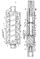
- FIGURE 1 is a front elevation of a portion of an interrupting module which includes an improved switch according to the present invention; and
- FIGURE 2 is a partially sectioned front elevation of a portion of FIG. 1 which shows in greater detail the improved switch hereof in the closed position.
- DETAILED DESCRIPTION Referring to FIGURE I, the
switch 22 of the present invention is for use as part of amodule 12. Themodule 12 includes a generally cylindrical open-endedinsulative housing 14, which is closed byend plates 16. The housing andend plates fusible element 18 helically wound around a central axis of thehousing 14 and may also surround a mass 20 of a particulate fulgurite-forming medium, such as silica sand. The silica sand is in intimate engagement with one or morefusible elements 18. Thefusible element 18, which may be silver, copper, or the like and the sand 20 interrupt fault currents or other over-currents therethrough in a current-limiting or energy-limiting manner, according to well-known principles. Thefusible element 18 may be similar to those disclosed in U.S. Patent Nos. 4,359,708 and 4,481,495. Thehousing 14 also surrounds theswitch 22 around which thefusible element 18 may be maintained in its helical configuration byinsulative supports 23. - The
switch 22, which is improved by the present invention, may be generally constructed in accordance with the aforemetnioned U.S. patent Nos.: 4,342,978; 4,370,531; 4,490,707; 4,494,103; 4,460,886; 4,467,307; and 4,499,446. Referring now to FIG. 2, theswitch 22 includes a firstconductive member 24, to which theleft end plate 16 is attached, and a secondconductive member 26 to which theright end plate 16 is attached. The firstconductive member 24 serves as a first stationary contact of theswitch 22, while the secondconductive member 26 serves as a second stationary contact of theswitch 22. The ends of thefusible element 18 may be rendered electrically continuous with thestationary contacts facililties 27 described more fully in U.S. Patent No. 4,491,820 Theswitch 22 also includes amovable contact 28. Normally, themovable contact 28 is electrically continuous with bothstationary contacts members movable contact 28. Because the impedance of this path is lower than the impedance of thefusible element 18, while theswitch 22 is closed, as depicted in FIGURE 2, all but a negligible portion of the current flowing through themodule 12 is normally shunted through theswitch 22 which is designed to carry much higher currents than the fusible element and away from thefusible element 18. When theswitch 22 opens, as described below, the current formerly flowing through thestationary contacts movable contact 28 is commutated to thefusible element 18 for interruption. - The first
stationary contact 24 has acentral bore 30. At the left end of thecentral bore 30, apower cartridge 32 or other pressure-generating device is located. The secondstationary contact 26 also contains acentral bore 36. This bore 36 may be lined with aninsulative sleeve 38. Themovable contact 28 comprises aconductive member 40 surrounded by aninsulative sleeve 42. Themovable contact 28 is normally located between thestationary contacts passageway 44 formed through aninsulative liner 46 between thestationary contacts - The
stationary contacts liner 46 are held with thebores passageway 44 aligned therebetween by aninsulative housing 48 which engageably surrounds thestationary contacts liner 46 may overlap thestationary contacts insulative support 23 may comprise notchedfins 49, and thefusible element 18 may be helically maintained about thehousing 48 by thefins 49. With themovable contact 28 occupying the position shown in FIGURE 2, theconductive member 40 thereof is electrically interconnected to thestationary contact 24 by aconductive shear disc 50 or other metallic diaphragm or member, which is shearable, tearable or the like. To the left of thediaphragm 50 is located aninsulative piston 52. In the normal position of themovable contact 28 shown in FIGURE 2, thepiston 52 normally occupies thebore 30 in the firststationary contact 24 and themovable contact 28 occupies thepassageway 44 in theliner 46. - In accordance with important aspects of the present invention, an energy-absorbing member or
element 51 is disposed between thepiston 52 and themovable contact 28. It is also preferred that the material used for the energy-absorbingelement 51 have excellent arc-extinguishing properties. The energy-absorbingelement 51 has a thickness that is defined in accordance with the material from which theelement 51 is fabricated, in accordance with its diameter, and in accordance with the amount of energy that must be absorbed to prevent rebounding or the formation of gaps between thepiston 52, the energy-absorbingelement 51, and themovable contact 28. The right end of theconductive member 40 is normally electrically interconnected to the secondstationary contact 26 by ashear disc 54, which may be similar to theshear disc 50. The interior of theinsulative sleeve 38 is sufficiently large to receive theconductive member 40 with itsinsulative sleeve 42 thereon. Thepassageway 44 of theliner 46 is suitably dimensioned to receive theconductive member 40 with theinsulative sleeve 42 thereon and thepiston 52. In preferred embodiments, thebores passageway 44, themovable contact 28, thepiston 52, the energy-absorbingelement 51, and the interior of thesleeve 38 all have circular cross-sections. - In the normal condition of the
module 12, as shown in FIGURE 2 and as previously described, theswitch 22 carries a majority of the current flowing in a protected high-voltage circuit (not shown) to which themodule 12 is connected. This current flows through thestationary contacts discs movable contact 28. Little current normally flows through thefusible element 18. Should a fault current or other over-current occur in the protected circuit (not shown) to which themodule 12 is sonnected, apparatus (not shown) detects this condition and ignites thepower cartridge 32. Ignition of thepower cartridge 32 causes it to evolve highpressure gas which acts on the left end of thepiston 52. The force applied to thepiston 52 by the high pressure moves thepiston 52 rightwardly. Additionally, themovable contact 28 including theconductive member 40 and theinsulative sleeve 42 also moves rightwardly via the transmission of force through the energy-absorbingelement 51. Rightward movement of thepiston 52 and of themovable contact 28 severs, rips or tears thediscs movable contact 28 and bothstationary contacts discs portions 50',50" and twoportions 54',54" respeetively. Two gaps are thereby opened by theswitch 22. The first gap exists between the left end of theconductive member 40 and the right end of the firststationary contact 24, while the second gap exists between the right end of theconductive member 40 and the left end of the secondstationary contact 26. Both gaps are electrically insulated. Specifically, the first gap is electrically insulated by the reception of thepiston 52 within thepassageway 44 in theliner 46. The second gap is electrically insulated by the reception of theinsulative sleeve 42 within thebore 36 of theinsulative sleeve 38. The reception of thepiston 52 by thepassageway 44 in theliner 46 is intended to compress and extinguish the arc that forms between themovable contact 28 and thestationary contact 24. In a preferred arrangement, alip seal 66 is provided at the end of thepiston 52 proximal to thepower cartridge 32. Thelip seal 66 comprises aninsulative body 67 containing ablind bore 68 formed in the end of thebody 67 proximal to thepower cartridge 32. Preferably, the sidewall of the blind bore 68 is flared so that pressure-produced forces acting thereon tend to deform or flare the exterior of thebody 67 outwardly. As set forth more fully in U.S. Patent No. 4,499,446, it has been found that the pressure produced by thepower cartridge 32 urges the exterior of thebody 67 into sealing engagement with thebore 30. This lessens the flow of ignition products past thelip seal 66 as thepiston 52 and thelip seal 66 move rightwardly. When theswitch 22 opens, the current previously flowing therethrough is commutated to thefusible element 18. The action of thefusible element 18 and of the silica sand 20 (FIGURE 1) ultimately extinguishes this current, as is well known. - While the pressure that is generated during opening exhibits a rapid rate of rise in a very short time (e.g. several hundred microseconds), the time for the force to travel through the
piston 52 to the right end thereof becomes an appreciable factor. Without the provision of the energy-absorbingelement 51, various dynamic-reaction or rebounding effects can occur between the piston and the movable contact, some of which may detract from the desired objective to move thepiston 52 and themovable contact 28 rapidly and simultaneously to rapidly open theswitch 22. For example, without the energy-absorbingelement 51, it is believed that at applicable rates of rise of pressure, forces transmitted through arigid piston 52 fabricated from a plastic such as polymethylpentene can cause rebounding at the interface between thepiston 52 and themovable contact 28. Accordingly, themovable contact 28 may at certain times move faster than thepiston 52. As a result, thepiston 52 is separated from the movable contact so as to require a small, but possibly significant, time interval to catch up to themovable contact 28. Additonally, due to reaction forces, it is even possible for thepiston 52 to be moving away from themovable contact 28 as themovable contact 28 moves rightwardly. These reaction effects can detract from the performance of theswitch 22. For example, as soon as the movable contact begins to move rightwardly, the gap of theswitch 22 can become excessively contaminated by arc products if thepiston 52 does not move along with themovable contact 28. Concerning themodule 12 of FIGURE 1, theswitch 22 is required to commutate high currents from the main current path of theswitch 22 to thefusible element 18. Specifically, the maximum instantaneous current that theswitch 22 can rapidly transfer to thefusible element 18 can be a limiting factor regarding the maximum interrupting capability of themodule 12 and the capability to interrupt high frequency currents. For example, the high currents must be transferred to thefusible element 18 before interruption can occur. Any excessive delay in the transfer time will cause thefusible element 18 to melt before the transfer of current from theswitch 22 to thefusible element 18 is complete. While arc voltage builds up as soon as themovable contact 28 begins to move so as to begin to transfer current to thefusible element 18, the transfer of current from the main current path of theswitch 22 to thefusible element 18 is enchanced by thepiston 52 entering thepassageway 44 in theliner 46. In summary, any delay in the movement of thepiston 52 reduces or detracts from the ability of theswitch 22 to rapidly transfer current to thefusible element 18. Additionally, any time interval during which thepiston 52 does not move along with themovable contact 28 can cause excessive contamination of the gap of theswitch 22 by the arc that forms between the movable contact and thestationary contact 26 which can further reduce the ability of theswitch 22 to transfer current to thefusible element 18. Of course, the magnitude of any dynamic reaction to cause the aforementioned condition depends on the properties and dimension of the associated parts. - In accordance with the present invention, the energy-absorbing
element 51 absorbs sufficient energy at the interface between thepiston 52 and themovable contact 28 to prevent rebounding caused by the transmission of forces between thepiston 52 and themovable contact 28. The energy-absorbingelement 51 functions as a buffer between thepiston 52 and themovable contact 28. - In one arrangement, the energy-absorbing
element 51 is formed as a cake or cylindrical solid from a suitable material providing interstices in the cake. During switch-opening operation, the high pressures transmitted through the piston crush the cake into a powdered state; the crushing action suitably absorbing energy to prevent undesirable dynamic interaction and rebounding between the piston and the movable contact. Further, the buffering interface provided by the energy-absorbingelement 51 prevents the formation of gaps between thepiston 52, the energy-absorbingelement 51, and themovable contact 28. Any such gaps would delay the transfer of current to the fusible element and thereby lead to excessive contamination of the switch gap by arc products. Further, such arc products reduce the dielectric strength of the switch; a sufficient dielectric strength being required to withstand the current-limiting arc voltage that is developed across the switch upon melting of thefusible element 18. In a specific arrangement, the material of the energy-absorbingelement 51 is selected to provide arc- extinghishing properties. In specific embodiments, the energy-absorbing element is fabricated form boric acid or polytetrafluoroethylene. Accordingly, the arc-extinguishing material aids in the interruption of current in the main current section of theswitch 22 as the energy-absorbingelement 51 is crushed and at least some of the material is distributed and dispersed along the interfaces of the various portions of the switch. - While the energy-absorbing
element 51 as described hereinbefore is entirely suitable for a variety of applications of the switch, the aforementioned description is intended in the form of specific exemplary arrangements and should not be interpreted in any limiting sense. Accordingly, it should also be realized that other materials and configurations for the energy-absorbingelement 51 are aslo possible other than as providing a crushing mechanism. For example, other materials for the energy-absorbingelement 51 are also suitable for the objective of the present invention which is to provide the absorbing of energy.
Claims (11)
Priority Applications (1)
| Application Number | Priority Date | Filing Date | Title |
|---|---|---|---|
| AT86307377T ATE63789T1 (en) | 1985-10-25 | 1986-09-25 | SWITCH FOR A HIGH VOLTAGE SWITCHING MODULE. |
Applications Claiming Priority (2)
| Application Number | Priority Date | Filing Date | Title |
|---|---|---|---|
| US791178 | 1985-10-25 | ||
| US06/791,178 US4692577A (en) | 1985-10-25 | 1985-10-25 | Switch for a high-voltage interrupting module |
Publications (3)
| Publication Number | Publication Date |
|---|---|
| EP0220837A2 true EP0220837A2 (en) | 1987-05-06 |
| EP0220837A3 EP0220837A3 (en) | 1989-08-02 |
| EP0220837B1 EP0220837B1 (en) | 1991-05-22 |
Family
ID=25152900
Family Applications (1)
| Application Number | Title | Priority Date | Filing Date |
|---|---|---|---|
| EP86307377A Expired - Lifetime EP0220837B1 (en) | 1985-10-25 | 1986-09-25 | Improved switch for a high-voltage interrupting module |
Country Status (5)
| Country | Link |
|---|---|
| US (1) | US4692577A (en) |
| EP (1) | EP0220837B1 (en) |
| AT (1) | ATE63789T1 (en) |
| CA (1) | CA1254602A (en) |
| DE (1) | DE3679370D1 (en) |
Families Citing this family (20)
| Publication number | Priority date | Publication date | Assignee | Title |
|---|---|---|---|---|
| US5952815A (en) * | 1997-07-25 | 1999-09-14 | Minnesota Mining & Manufacturing Co. | Equalizer system and method for series connected energy storing devices |
| US6104967A (en) * | 1997-07-25 | 2000-08-15 | 3M Innovative Properties Company | Fault-tolerant battery system employing intra-battery network architecture |
| US6146778A (en) | 1997-07-25 | 2000-11-14 | 3M Innovative Properties Company | Solid-state energy storage module employing integrated interconnect board |
| US6099986A (en) * | 1997-07-25 | 2000-08-08 | 3M Innovative Properties Company | In-situ short circuit protection system and method for high-energy electrochemical cells |
| US6100702A (en) * | 1997-07-25 | 2000-08-08 | 3M Innovative Properties Company | In-situ fault detection apparatus and method for an encased energy storing device |
| US6087036A (en) * | 1997-07-25 | 2000-07-11 | 3M Innovative Properties Company | Thermal management system and method for a solid-state energy storing device |
| US6117584A (en) * | 1997-07-25 | 2000-09-12 | 3M Innovative Properties Company | Thermal conductor for high-energy electrochemical cells |
| US6046514A (en) * | 1997-07-25 | 2000-04-04 | 3M Innovative Properties Company | Bypass apparatus and method for series connected energy storage devices |
| US6120930A (en) | 1997-07-25 | 2000-09-19 | 3M Innovative Properties Corporation | Rechargeable thin-film electrochemical generator |
| US6235425B1 (en) | 1997-12-12 | 2001-05-22 | 3M Innovative Properties Company | Apparatus and method for treating a cathode material provided on a thin-film substrate |
| US7772958B2 (en) * | 2004-09-09 | 2010-08-10 | Lisa Dräxlmaier GmbH | Load shedder |
| DE102007014339A1 (en) * | 2007-03-26 | 2008-10-02 | Robert Bosch Gmbh | Thermal fuse for use in electrical modules |
| CA171088S (en) * | 2016-04-22 | 2018-01-15 | Siemens Ag | Transformer |
| CA170961S (en) * | 2016-04-22 | 2017-10-30 | Siemens Ag | Power transformer |
| USD829659S1 (en) * | 2016-05-17 | 2018-10-02 | Eaton Intelligent Power Limited | Conductor |
| USD801930S1 (en) * | 2016-05-17 | 2017-11-07 | Eaton Corporation | Conductor |
| USD829660S1 (en) * | 2016-05-17 | 2018-10-02 | Eaton Intelligent Power Limited | Conductor |
| USD795809S1 (en) * | 2016-05-17 | 2017-08-29 | Eaton Corporation | Conductor |
| EP4095876B1 (en) * | 2021-05-25 | 2023-12-27 | ABB S.p.A. | Breaking device |
| EP4113561B1 (en) * | 2021-06-30 | 2024-02-07 | ABB S.p.A. | Breaking device |
Citations (5)
| Publication number | Priority date | Publication date | Assignee | Title |
|---|---|---|---|---|
| GB979854A (en) * | 1960-03-24 | 1965-01-06 | Graviner Manufacturing Co | Improvements in or relating to explosively operated electric switches |
| US3264438A (en) * | 1964-04-29 | 1966-08-02 | Atlas Chem Ind | Positive action circuit breaking switch |
| US4460886A (en) * | 1982-11-01 | 1984-07-17 | S&C Electric Company | Pressure-operated switch for a current-limiting, high-voltage interrupting module |
| US4494103A (en) * | 1980-08-18 | 1985-01-15 | S&C Electric Company | High-speed, multi-break electrical switch |
| EP0134071A2 (en) * | 1983-08-17 | 1985-03-13 | S & C ELECTRIC COMPANY | Pressure-operated switch for a high-voltage interrupting module |
Family Cites Families (8)
| Publication number | Priority date | Publication date | Assignee | Title |
|---|---|---|---|---|
| US2277422A (en) * | 1940-03-08 | 1942-03-24 | Gen Electric | Electric circuit breaker |
| US2477837A (en) * | 1944-08-25 | 1949-08-02 | Westinghouse Electric Corp | Circuit interrupter |
| GB930980A (en) * | 1960-04-13 | 1963-07-10 | Jose Munoz De Vargas | Improvements in electric switches |
| BE635001A (en) * | 1962-07-16 | |||
| US4342978A (en) * | 1979-03-19 | 1982-08-03 | S&C Electric Company | Explosively-actuated switch and current limiting, high voltage fuse using same |
| US4490707A (en) * | 1980-08-18 | 1984-12-25 | S&C Electric Company | Explosively-actuated, multi-gap high voltage switch |
| US4370531A (en) * | 1980-09-19 | 1983-01-25 | S&C Electric Company | Electric switch and improved device using same |
| US4499446A (en) * | 1983-08-22 | 1985-02-12 | S&C Electric Company | Pressure-operated switch for a high-voltage interrupting module |
-
1985
- 1985-10-25 US US06/791,178 patent/US4692577A/en not_active Expired - Lifetime
-
1986
- 1986-07-03 CA CA000513007A patent/CA1254602A/en not_active Expired
- 1986-09-25 AT AT86307377T patent/ATE63789T1/en not_active IP Right Cessation
- 1986-09-25 DE DE8686307377T patent/DE3679370D1/en not_active Expired - Fee Related
- 1986-09-25 EP EP86307377A patent/EP0220837B1/en not_active Expired - Lifetime
Patent Citations (5)
| Publication number | Priority date | Publication date | Assignee | Title |
|---|---|---|---|---|
| GB979854A (en) * | 1960-03-24 | 1965-01-06 | Graviner Manufacturing Co | Improvements in or relating to explosively operated electric switches |
| US3264438A (en) * | 1964-04-29 | 1966-08-02 | Atlas Chem Ind | Positive action circuit breaking switch |
| US4494103A (en) * | 1980-08-18 | 1985-01-15 | S&C Electric Company | High-speed, multi-break electrical switch |
| US4460886A (en) * | 1982-11-01 | 1984-07-17 | S&C Electric Company | Pressure-operated switch for a current-limiting, high-voltage interrupting module |
| EP0134071A2 (en) * | 1983-08-17 | 1985-03-13 | S & C ELECTRIC COMPANY | Pressure-operated switch for a high-voltage interrupting module |
Also Published As
| Publication number | Publication date |
|---|---|
| EP0220837B1 (en) | 1991-05-22 |
| CA1254602A (en) | 1989-05-23 |
| US4692577A (en) | 1987-09-08 |
| DE3679370D1 (en) | 1991-06-27 |
| ATE63789T1 (en) | 1991-06-15 |
| EP0220837A3 (en) | 1989-08-02 |
Similar Documents
| Publication | Publication Date | Title |
|---|---|---|
| EP0220837B1 (en) | Improved switch for a high-voltage interrupting module | |
| US4342978A (en) | Explosively-actuated switch and current limiting, high voltage fuse using same | |
| CA1231360B (en) | Multi-gap high-voltage switch | |
| US4370531A (en) | Electric switch and improved device using same | |
| US4490707A (en) | Explosively-actuated, multi-gap high voltage switch | |
| US4065741A (en) | Thermal fuse with a fusible temperature sensitive pellet | |
| US4691085A (en) | High voltage interrupting switch with improved contact connection arrangement and method | |
| EP0210778B1 (en) | Fuse for an alternating current power circuit | |
| US4460886A (en) | Pressure-operated switch for a current-limiting, high-voltage interrupting module | |
| IE852967L (en) | Electric switch¹852968¹¹¹during breaking | |
| EP0134071B1 (en) | Pressure-operated switch for a high-voltage interrupting module | |
| US4494103A (en) | High-speed, multi-break electrical switch | |
| US4499446A (en) | Pressure-operated switch for a high-voltage interrupting module | |
| EP0135247B1 (en) | Pressure-operated switch for a high-voltage interrupting module | |
| CA1196941A (en) | Brake and operation indicator for a high-voltage switch | |
| US4680434A (en) | Explosive-driven, high speed, arcless switch | |
| US4183005A (en) | Circuit interrupting device | |
| CA1129460A (en) | Pressure-operated high-voltage circuit protecting device with high continuous current rating | |
| US4472704A (en) | Pressure-operated switch for a high-voltage interrupting module | |
| USRE32321E (en) | Electric switch and improved device using same | |
| EP0133632B1 (en) | Improved high-speed, multi-break electrical switch | |
| CN220208763U (en) | Self-triggering arc-extinguishing intelligent switch | |
| US4229723A (en) | Diaphragm having a pattern of reduced thickness in a high voltage, circuit-interrupting device | |
| RU2177186C2 (en) | Expulsion fuse | |
| US4491820A (en) | Device for terminating a fusible element of an interrupting module |
Legal Events
| Date | Code | Title | Description |
|---|---|---|---|
| PUAI | Public reference made under article 153(3) epc to a published international application that has entered the european phase |
Free format text: ORIGINAL CODE: 0009012 |
|
| AK | Designated contracting states |
Kind code of ref document: A2 Designated state(s): AT BE CH DE FR GB IT LI NL SE |
|
| PUAL | Search report despatched |
Free format text: ORIGINAL CODE: 0009013 |
|
| AK | Designated contracting states |
Kind code of ref document: A3 Designated state(s): AT BE CH DE FR GB IT LI NL SE |
|
| 17P | Request for examination filed |
Effective date: 19900119 |
|
| 17Q | First examination report despatched |
Effective date: 19900726 |
|
| GRAA | (expected) grant |
Free format text: ORIGINAL CODE: 0009210 |
|
| STAA | Information on the status of an ep patent application or granted ep patent |
Free format text: STATUS: THE PATENT HAS BEEN GRANTED |
|
| AK | Designated contracting states |
Kind code of ref document: B1 Designated state(s): AT BE CH DE FR GB IT LI NL SE |
|
| PG25 | Lapsed in a contracting state [announced via postgrant information from national office to epo] |
Ref country code: IT Free format text: LAPSE BECAUSE OF FAILURE TO SUBMIT A TRANSLATION OF THE DESCRIPTION OR TO PAY THE FEE WITHIN THE PRESCRIBED TIME-LIMIT;WARNING: LAPSES OF ITALIAN PATENTS WITH EFFECTIVE DATE BEFORE 2007 MAY HAVE OCCURRED AT ANY TIME BEFORE 2007. THE CORRECT EFFECTIVE DATE MAY BE DIFFERENT FROM THE ONE RECORDED. Effective date: 19910522 Ref country code: AT Effective date: 19910522 Ref country code: NL Effective date: 19910522 Ref country code: SE Effective date: 19910522 |
|
| REF | Corresponds to: |
Ref document number: 63789 Country of ref document: AT Date of ref document: 19910615 Kind code of ref document: T |
|
| REF | Corresponds to: |
Ref document number: 3679370 Country of ref document: DE Date of ref document: 19910627 |
|
| ET | Fr: translation filed | ||
| NLV1 | Nl: lapsed or annulled due to failure to fulfill the requirements of art. 29p and 29m of the patents act | ||
| PLBE | No opposition filed within time limit |
Free format text: ORIGINAL CODE: 0009261 |
|
| 26N | No opposition filed | ||
| PGFP | Annual fee paid to national office [announced via postgrant information from national office to epo] |
Ref country code: FR Payment date: 20010911 Year of fee payment: 16 |
|
| PGFP | Annual fee paid to national office [announced via postgrant information from national office to epo] |
Ref country code: GB Payment date: 20010926 Year of fee payment: 16 |
|
| PGFP | Annual fee paid to national office [announced via postgrant information from national office to epo] |
Ref country code: DE Payment date: 20011009 Year of fee payment: 16 |
|
| PGFP | Annual fee paid to national office [announced via postgrant information from national office to epo] |
Ref country code: CH Payment date: 20011015 Year of fee payment: 16 |
|
| PGFP | Annual fee paid to national office [announced via postgrant information from national office to epo] |
Ref country code: BE Payment date: 20011116 Year of fee payment: 16 |
|
| REG | Reference to a national code |
Ref country code: GB Ref legal event code: IF02 |
|
| PG25 | Lapsed in a contracting state [announced via postgrant information from national office to epo] |
Ref country code: GB Free format text: LAPSE BECAUSE OF NON-PAYMENT OF DUE FEES Effective date: 20020925 |
|
| PG25 | Lapsed in a contracting state [announced via postgrant information from national office to epo] |
Ref country code: CH Free format text: LAPSE BECAUSE OF NON-PAYMENT OF DUE FEES Effective date: 20020930 Ref country code: LI Free format text: LAPSE BECAUSE OF NON-PAYMENT OF DUE FEES Effective date: 20020930 Ref country code: BE Free format text: LAPSE BECAUSE OF NON-PAYMENT OF DUE FEES Effective date: 20020930 |
|
| BERE | Be: lapsed |
Owner name: *S & C ELECTRIC CY Effective date: 20020930 |
|
| PG25 | Lapsed in a contracting state [announced via postgrant information from national office to epo] |
Ref country code: DE Free format text: LAPSE BECAUSE OF NON-PAYMENT OF DUE FEES Effective date: 20030401 |
|
| GBPC | Gb: european patent ceased through non-payment of renewal fee |
Effective date: 20020925 |
|
| REG | Reference to a national code |
Ref country code: CH Ref legal event code: PL |
|
| PG25 | Lapsed in a contracting state [announced via postgrant information from national office to epo] |
Ref country code: FR Free format text: LAPSE BECAUSE OF NON-PAYMENT OF DUE FEES Effective date: 20030603 |
|
| REG | Reference to a national code |
Ref country code: FR Ref legal event code: ST |