EP0220959B1 - Ceramic electronic device and method of manufacturing the same - Google Patents
Ceramic electronic device and method of manufacturing the same Download PDFInfo
- Publication number
- EP0220959B1 EP0220959B1 EP86308344A EP86308344A EP0220959B1 EP 0220959 B1 EP0220959 B1 EP 0220959B1 EP 86308344 A EP86308344 A EP 86308344A EP 86308344 A EP86308344 A EP 86308344A EP 0220959 B1 EP0220959 B1 EP 0220959B1
- Authority
- EP
- European Patent Office
- Prior art keywords
- ceramic
- green sheet
- pattern
- laminated body
- ink
- Prior art date
- Legal status (The legal status is an assumption and is not a legal conclusion. Google has not performed a legal analysis and makes no representation as to the accuracy of the status listed.)
- Expired - Lifetime
Links
- 239000000919 ceramic Substances 0.000 title claims description 124
- 238000004519 manufacturing process Methods 0.000 title claims description 38
- 239000011347 resin Substances 0.000 claims description 52
- 229920005989 resin Polymers 0.000 claims description 52
- 238000000034 method Methods 0.000 claims description 38
- 239000011368 organic material Substances 0.000 claims description 19
- 239000000463 material Substances 0.000 claims description 18
- 239000011230 binding agent Substances 0.000 claims description 17
- 229910010293 ceramic material Inorganic materials 0.000 claims description 15
- 238000005245 sintering Methods 0.000 claims description 15
- 238000003825 pressing Methods 0.000 claims description 9
- 239000000853 adhesive Substances 0.000 claims description 5
- 230000001070 adhesive effect Effects 0.000 claims description 5
- 238000005520 cutting process Methods 0.000 claims description 5
- 238000010438 heat treatment Methods 0.000 claims description 5
- 230000001681 protective effect Effects 0.000 claims description 5
- 238000004080 punching Methods 0.000 claims description 3
- 230000005540 biological transmission Effects 0.000 claims description 2
- 238000007639 printing Methods 0.000 claims description 2
- 239000003990 capacitor Substances 0.000 claims 1
- 229910052751 metal Inorganic materials 0.000 description 19
- 239000002184 metal Substances 0.000 description 19
- 239000002002 slurry Substances 0.000 description 12
- 239000000843 powder Substances 0.000 description 9
- 238000007796 conventional method Methods 0.000 description 7
- NIXOWILDQLNWCW-UHFFFAOYSA-N acrylic acid group Chemical group C(C=C)(=O)O NIXOWILDQLNWCW-UHFFFAOYSA-N 0.000 description 6
- 239000012298 atmosphere Substances 0.000 description 6
- 230000015572 biosynthetic process Effects 0.000 description 6
- 239000002985 plastic film Substances 0.000 description 6
- 229920006255 plastic film Polymers 0.000 description 6
- 229910020698 PbZrO3 Inorganic materials 0.000 description 5
- QVGXLLKOCUKJST-UHFFFAOYSA-N atomic oxygen Chemical compound [O] QVGXLLKOCUKJST-UHFFFAOYSA-N 0.000 description 5
- 238000005452 bending Methods 0.000 description 5
- 238000005266 casting Methods 0.000 description 5
- 229910052760 oxygen Inorganic materials 0.000 description 5
- 239000001301 oxygen Substances 0.000 description 5
- 238000007650 screen-printing Methods 0.000 description 5
- 239000002904 solvent Substances 0.000 description 5
- 239000004925 Acrylic resin Substances 0.000 description 4
- 229920000178 Acrylic resin Polymers 0.000 description 4
- ZWEHNKRNPOVVGH-UHFFFAOYSA-N Methyl ethyl ketone Natural products CCC(C)=O ZWEHNKRNPOVVGH-UHFFFAOYSA-N 0.000 description 4
- 230000015556 catabolic process Effects 0.000 description 4
- 238000006731 degradation reaction Methods 0.000 description 4
- 238000007606 doctor blade method Methods 0.000 description 4
- 230000000694 effects Effects 0.000 description 4
- 239000007772 electrode material Substances 0.000 description 4
- 239000011521 glass Substances 0.000 description 4
- 238000002347 injection Methods 0.000 description 4
- 239000007924 injection Substances 0.000 description 4
- 229920006267 polyester film Polymers 0.000 description 4
- 239000000758 substrate Substances 0.000 description 4
- OKTJSMMVPCPJKN-UHFFFAOYSA-N Carbon Chemical compound [C] OKTJSMMVPCPJKN-UHFFFAOYSA-N 0.000 description 3
- 229910052799 carbon Inorganic materials 0.000 description 3
- 238000003475 lamination Methods 0.000 description 3
- 239000000203 mixture Substances 0.000 description 3
- 230000007261 regionalization Effects 0.000 description 3
- 239000004677 Nylon Substances 0.000 description 2
- BQCADISMDOOEFD-UHFFFAOYSA-N Silver Chemical compound [Ag] BQCADISMDOOEFD-UHFFFAOYSA-N 0.000 description 2
- 239000002585 base Substances 0.000 description 2
- 239000003985 ceramic capacitor Substances 0.000 description 2
- 239000004020 conductor Substances 0.000 description 2
- 238000010276 construction Methods 0.000 description 2
- 230000003247 decreasing effect Effects 0.000 description 2
- 230000000593 degrading effect Effects 0.000 description 2
- 239000002003 electrode paste Substances 0.000 description 2
- 238000005530 etching Methods 0.000 description 2
- 230000001788 irregular Effects 0.000 description 2
- 238000010030 laminating Methods 0.000 description 2
- 239000007769 metal material Substances 0.000 description 2
- 238000000465 moulding Methods 0.000 description 2
- 229920001778 nylon Polymers 0.000 description 2
- 239000011295 pitch Substances 0.000 description 2
- BASFCYQUMIYNBI-UHFFFAOYSA-N platinum Chemical compound [Pt] BASFCYQUMIYNBI-UHFFFAOYSA-N 0.000 description 2
- 230000010287 polarization Effects 0.000 description 2
- 229910052709 silver Inorganic materials 0.000 description 2
- 239000004332 silver Substances 0.000 description 2
- 239000004593 Epoxy Substances 0.000 description 1
- 239000005062 Polybutadiene Substances 0.000 description 1
- ATJFFYVFTNAWJD-UHFFFAOYSA-N Tin Chemical compound [Sn] ATJFFYVFTNAWJD-UHFFFAOYSA-N 0.000 description 1
- 239000003513 alkali Substances 0.000 description 1
- PNEYBMLMFCGWSK-UHFFFAOYSA-N aluminium oxide Inorganic materials [O-2].[O-2].[O-2].[Al+3].[Al+3] PNEYBMLMFCGWSK-UHFFFAOYSA-N 0.000 description 1
- 239000005388 borosilicate glass Substances 0.000 description 1
- 238000006243 chemical reaction Methods 0.000 description 1
- 239000003795 chemical substances by application Substances 0.000 description 1
- 238000000576 coating method Methods 0.000 description 1
- 229910003460 diamond Inorganic materials 0.000 description 1
- 239000010432 diamond Substances 0.000 description 1
- 230000005684 electric field Effects 0.000 description 1
- 238000007772 electroless plating Methods 0.000 description 1
- 239000003822 epoxy resin Substances 0.000 description 1
- 230000009477 glass transition Effects 0.000 description 1
- 238000005470 impregnation Methods 0.000 description 1
- 230000002452 interceptive effect Effects 0.000 description 1
- 238000004806 packaging method and process Methods 0.000 description 1
- 238000000059 patterning Methods 0.000 description 1
- 239000004033 plastic Substances 0.000 description 1
- 229920003023 plastic Polymers 0.000 description 1
- 229910052697 platinum Inorganic materials 0.000 description 1
- 238000005498 polishing Methods 0.000 description 1
- 229920002857 polybutadiene Polymers 0.000 description 1
- 229920000647 polyepoxide Polymers 0.000 description 1
- 229920005749 polyurethane resin Polymers 0.000 description 1
- 238000002360 preparation method Methods 0.000 description 1
- 229910001925 ruthenium oxide Inorganic materials 0.000 description 1
- WOCIAKWEIIZHES-UHFFFAOYSA-N ruthenium(iv) oxide Chemical compound O=[Ru]=O WOCIAKWEIIZHES-UHFFFAOYSA-N 0.000 description 1
- 238000010345 tape casting Methods 0.000 description 1
Images


Classifications
-
- H—ELECTRICITY
- H01—ELECTRIC ELEMENTS
- H01K—ELECTRIC INCANDESCENT LAMPS
- H01K3/00—Apparatus or processes adapted to the manufacture, installing, removal, or maintenance of incandescent lamps or parts thereof
- H01K3/22—Exhausting, degassing, filling, or cleaning vessels
-
- B—PERFORMING OPERATIONS; TRANSPORTING
- B41—PRINTING; LINING MACHINES; TYPEWRITERS; STAMPS
- B41J—TYPEWRITERS; SELECTIVE PRINTING MECHANISMS, i.e. MECHANISMS PRINTING OTHERWISE THAN FROM A FORME; CORRECTION OF TYPOGRAPHICAL ERRORS
- B41J2/00—Typewriters or selective printing mechanisms characterised by the printing or marking process for which they are designed
- B41J2/005—Typewriters or selective printing mechanisms characterised by the printing or marking process for which they are designed characterised by bringing liquid or particles selectively into contact with a printing material
- B41J2/01—Ink jet
- B41J2/135—Nozzles
- B41J2/16—Production of nozzles
- B41J2/1607—Production of print heads with piezoelectric elements
- B41J2/1609—Production of print heads with piezoelectric elements of finger type, chamber walls consisting integrally of piezoelectric material
-
- B—PERFORMING OPERATIONS; TRANSPORTING
- B41—PRINTING; LINING MACHINES; TYPEWRITERS; STAMPS
- B41J—TYPEWRITERS; SELECTIVE PRINTING MECHANISMS, i.e. MECHANISMS PRINTING OTHERWISE THAN FROM A FORME; CORRECTION OF TYPOGRAPHICAL ERRORS
- B41J2/00—Typewriters or selective printing mechanisms characterised by the printing or marking process for which they are designed
- B41J2/005—Typewriters or selective printing mechanisms characterised by the printing or marking process for which they are designed characterised by bringing liquid or particles selectively into contact with a printing material
- B41J2/01—Ink jet
- B41J2/135—Nozzles
- B41J2/16—Production of nozzles
- B41J2/1621—Manufacturing processes
- B41J2/1631—Manufacturing processes photolithography
-
- B—PERFORMING OPERATIONS; TRANSPORTING
- B41—PRINTING; LINING MACHINES; TYPEWRITERS; STAMPS
- B41J—TYPEWRITERS; SELECTIVE PRINTING MECHANISMS, i.e. MECHANISMS PRINTING OTHERWISE THAN FROM A FORME; CORRECTION OF TYPOGRAPHICAL ERRORS
- B41J2/00—Typewriters or selective printing mechanisms characterised by the printing or marking process for which they are designed
- B41J2/005—Typewriters or selective printing mechanisms characterised by the printing or marking process for which they are designed characterised by bringing liquid or particles selectively into contact with a printing material
- B41J2/01—Ink jet
- B41J2/135—Nozzles
- B41J2/16—Production of nozzles
- B41J2/1621—Manufacturing processes
- B41J2/1632—Manufacturing processes machining
-
- C—CHEMISTRY; METALLURGY
- C04—CEMENTS; CONCRETE; ARTIFICIAL STONE; CERAMICS; REFRACTORIES
- C04B—LIME, MAGNESIA; SLAG; CEMENTS; COMPOSITIONS THEREOF, e.g. MORTARS, CONCRETE OR LIKE BUILDING MATERIALS; ARTIFICIAL STONE; CERAMICS; REFRACTORIES; TREATMENT OF NATURAL STONE
- C04B41/00—After-treatment of mortars, concrete, artificial stone or ceramics; Treatment of natural stone
- C04B41/009—After-treatment of mortars, concrete, artificial stone or ceramics; Treatment of natural stone characterised by the material treated
-
- C—CHEMISTRY; METALLURGY
- C04—CEMENTS; CONCRETE; ARTIFICIAL STONE; CERAMICS; REFRACTORIES
- C04B—LIME, MAGNESIA; SLAG; CEMENTS; COMPOSITIONS THEREOF, e.g. MORTARS, CONCRETE OR LIKE BUILDING MATERIALS; ARTIFICIAL STONE; CERAMICS; REFRACTORIES; TREATMENT OF NATURAL STONE
- C04B41/00—After-treatment of mortars, concrete, artificial stone or ceramics; Treatment of natural stone
- C04B41/45—Coating or impregnating, e.g. injection in masonry, partial coating of green or fired ceramics, organic coating compositions for adhering together two concrete elements
- C04B41/50—Coating or impregnating, e.g. injection in masonry, partial coating of green or fired ceramics, organic coating compositions for adhering together two concrete elements with inorganic materials
- C04B41/51—Metallising, e.g. infiltration of sintered ceramic preforms with molten metal
- C04B41/5194—Metallisation of multilayered ceramics, e.g. for the fabrication of multilayer ceramic capacitors
-
- C—CHEMISTRY; METALLURGY
- C04—CEMENTS; CONCRETE; ARTIFICIAL STONE; CERAMICS; REFRACTORIES
- C04B—LIME, MAGNESIA; SLAG; CEMENTS; COMPOSITIONS THEREOF, e.g. MORTARS, CONCRETE OR LIKE BUILDING MATERIALS; ARTIFICIAL STONE; CERAMICS; REFRACTORIES; TREATMENT OF NATURAL STONE
- C04B41/00—After-treatment of mortars, concrete, artificial stone or ceramics; Treatment of natural stone
- C04B41/80—After-treatment of mortars, concrete, artificial stone or ceramics; Treatment of natural stone of only ceramics
- C04B41/81—Coating or impregnation
- C04B41/85—Coating or impregnation with inorganic materials
- C04B41/88—Metals
-
- H—ELECTRICITY
- H01—ELECTRIC ELEMENTS
- H01L—SEMICONDUCTOR DEVICES NOT COVERED BY CLASS H10
- H01L21/00—Processes or apparatus adapted for the manufacture or treatment of semiconductor or solid state devices or of parts thereof
- H01L21/70—Manufacture or treatment of devices consisting of a plurality of solid state components formed in or on a common substrate or of parts thereof; Manufacture of integrated circuit devices or of parts thereof
- H01L21/702—Manufacture or treatment of devices consisting of a plurality of solid state components formed in or on a common substrate or of parts thereof; Manufacture of integrated circuit devices or of parts thereof of thick-or thin-film circuits or parts thereof
- H01L21/705—Manufacture or treatment of devices consisting of a plurality of solid state components formed in or on a common substrate or of parts thereof; Manufacture of integrated circuit devices or of parts thereof of thick-or thin-film circuits or parts thereof of thick-film circuits or parts thereof
-
- H—ELECTRICITY
- H03—ELECTRONIC CIRCUITRY
- H03H—IMPEDANCE NETWORKS, e.g. RESONANT CIRCUITS; RESONATORS
- H03H9/00—Networks comprising electromechanical or electro-acoustic devices; Electromechanical resonators
- H03H9/15—Constructional features of resonators consisting of piezoelectric or electrostrictive material
- H03H9/17—Constructional features of resonators consisting of piezoelectric or electrostrictive material having a single resonator
- H03H9/176—Constructional features of resonators consisting of piezoelectric or electrostrictive material having a single resonator consisting of ceramic material
-
- H—ELECTRICITY
- H03—ELECTRONIC CIRCUITRY
- H03H—IMPEDANCE NETWORKS, e.g. RESONANT CIRCUITS; RESONATORS
- H03H9/00—Networks comprising electromechanical or electro-acoustic devices; Electromechanical resonators
- H03H9/46—Filters
- H03H9/54—Filters comprising resonators of piezo-electric or electrostrictive material
- H03H9/56—Monolithic crystal filters
- H03H9/562—Monolithic crystal filters comprising a ceramic piezoelectric layer
-
- B—PERFORMING OPERATIONS; TRANSPORTING
- B41—PRINTING; LINING MACHINES; TYPEWRITERS; STAMPS
- B41J—TYPEWRITERS; SELECTIVE PRINTING MECHANISMS, i.e. MECHANISMS PRINTING OTHERWISE THAN FROM A FORME; CORRECTION OF TYPOGRAPHICAL ERRORS
- B41J2/00—Typewriters or selective printing mechanisms characterised by the printing or marking process for which they are designed
- B41J2/005—Typewriters or selective printing mechanisms characterised by the printing or marking process for which they are designed characterised by bringing liquid or particles selectively into contact with a printing material
- B41J2/01—Ink jet
- B41J2/135—Nozzles
- B41J2/14—Structure thereof only for on-demand ink jet heads
- B41J2/14201—Structure of print heads with piezoelectric elements
- B41J2/14209—Structure of print heads with piezoelectric elements of finger type, chamber walls consisting integrally of piezoelectric material
- B41J2002/14217—Multi layer finger type piezoelectric element
-
- C—CHEMISTRY; METALLURGY
- C04—CEMENTS; CONCRETE; ARTIFICIAL STONE; CERAMICS; REFRACTORIES
- C04B—LIME, MAGNESIA; SLAG; CEMENTS; COMPOSITIONS THEREOF, e.g. MORTARS, CONCRETE OR LIKE BUILDING MATERIALS; ARTIFICIAL STONE; CERAMICS; REFRACTORIES; TREATMENT OF NATURAL STONE
- C04B2111/00—Mortars, concrete or artificial stone or mixtures to prepare them, characterised by specific function, property or use
- C04B2111/00474—Uses not provided for elsewhere in C04B2111/00
- C04B2111/00844—Uses not provided for elsewhere in C04B2111/00 for electronic applications
-
- H—ELECTRICITY
- H04—ELECTRIC COMMUNICATION TECHNIQUE
- H04R—LOUDSPEAKERS, MICROPHONES, GRAMOPHONE PICK-UPS OR LIKE ACOUSTIC ELECTROMECHANICAL TRANSDUCERS; DEAF-AID SETS; PUBLIC ADDRESS SYSTEMS
- H04R17/00—Piezoelectric transducers; Electrostrictive transducers
- H04R17/04—Gramophone pick-ups using a stylus; Recorders using a stylus
- H04R17/08—Gramophone pick-ups using a stylus; Recorders using a stylus signals being recorded or played back by vibration of a stylus in two orthogonal directions simultaneously
-
- Y—GENERAL TAGGING OF NEW TECHNOLOGICAL DEVELOPMENTS; GENERAL TAGGING OF CROSS-SECTIONAL TECHNOLOGIES SPANNING OVER SEVERAL SECTIONS OF THE IPC; TECHNICAL SUBJECTS COVERED BY FORMER USPC CROSS-REFERENCE ART COLLECTIONS [XRACs] AND DIGESTS
- Y10—TECHNICAL SUBJECTS COVERED BY FORMER USPC
- Y10T—TECHNICAL SUBJECTS COVERED BY FORMER US CLASSIFICATION
- Y10T29/00—Metal working
- Y10T29/49—Method of mechanical manufacture
- Y10T29/49002—Electrical device making
- Y10T29/49082—Resistor making
- Y10T29/49083—Heater type
-
- Y—GENERAL TAGGING OF NEW TECHNOLOGICAL DEVELOPMENTS; GENERAL TAGGING OF CROSS-SECTIONAL TECHNOLOGIES SPANNING OVER SEVERAL SECTIONS OF THE IPC; TECHNICAL SUBJECTS COVERED BY FORMER USPC CROSS-REFERENCE ART COLLECTIONS [XRACs] AND DIGESTS
- Y10—TECHNICAL SUBJECTS COVERED BY FORMER USPC
- Y10T—TECHNICAL SUBJECTS COVERED BY FORMER US CLASSIFICATION
- Y10T29/00—Metal working
- Y10T29/49—Method of mechanical manufacture
- Y10T29/49002—Electrical device making
- Y10T29/49117—Conductor or circuit manufacturing
- Y10T29/49124—On flat or curved insulated base, e.g., printed circuit, etc.
- Y10T29/49155—Manufacturing circuit on or in base
- Y10T29/49158—Manufacturing circuit on or in base with molding of insulated base
Definitions
- the present invention relates to a ceramic electronic device and a method of manufacturing the same.
- a paste such as a carbon paste to be decomposed and removed at a temperature up to a ceramic sintering temperature is coated in ceramic plates, or a press plate is compressed on a ceramic green sheet.
- a paste containing carbon is coated on a green sheet, and sheets including the sheet with a paste layer were stacked, pressed and sintered to form cavities at the paste portions.
- a metal such as silver, lead or tin is impregnated in the cavities under pressure to form internal electrodes (Fabrication of Multilayer Ceramic Capacitors by Metal Impregnation; IEEE TRANSACTION ON PARTS, HYBRIDS, AND PACKAGING, VOL. PHP-9, No. 3 SEPT. 1973, pp. 144 - 147).
- the first drawback of a piezoelectric electroacoustic transducer device prepared by conventional techniques lies in the fact that a piezoelectric plate, an elastic plate, and a casing are separately prepared and are finally assembled together. In order to assemble such devices in the mass production line, a large number of assembly steps are required. Even if an automated assembly system is used, a considerably high investment capital is required, thus increasing the product cost.
- the second drawback of the piezoelectric electroacoustic transducer device is degradation of the performance and reliability caused by adhering the piezoelectric and elastic plates by an adhesive or the like. If a bending resonator is flexed upon reception of an electrical signal or an external sound pressure, a large stress is concentrated in the adhesion layer portion. If the transducer is driven at a large amplitude for a long period of time, the adhesion layer is damaged. In addition, vibration energy is absorbed in the adhesion layer to degrade operational efficiency. Furthermore, the temperature characteristics of the transducer are degraded by an influence of the adhesive.
- the third drawback of the piezoelectric electroacoustic transducer device is the limitations of a decrease in thickness of the piezoelectric plate.
- the resonant frequency of the bending resonator is proportional to its thickness and is in inverse proportion to the square of its diameter.
- the thickness of the piezoelectric plate In order to obtain a compact transducer device usable in a low frequency, the thickness of the piezoelectric plate must be minimized.
- its thickness is limited, as described above. Even if a thin piezoelectric plate is prepared, it is mechanically damaged when it is adhered to the elastic plate. Therefore, as compared with the case wherein a piezoelectric plate having a relatively large thickness is used, the yield of the piezoelectric plates is greatly decreased.
- the fourth drawback of the piezoelectric electroacoustic transducer device is to require fine finish for forming a flat surface of the piezoelectric plate.
- the plate Upon adhesion of the piezoelectric plate to the elastic plate, if the piezoelectric plate is warped or has a large recess, the plate is damaged and the contact density of the piezoelectric plate adhered to the elastic plate is undesirably decreased. Furthermore, incomplete adhesion also leads to the degradation of energy conversion efficiency of the bending resonator.
- a metal press plate is pressed on a green sheet or an acrylic die is set in a green sheet, thereby forming cavities (Japanese Patent Prepublication No. 58-87060).
- the conventional cavity or space formation method satisfactory precision cannot be obtained, or the height of the cavity is undesirably small.
- the minimum order is restricted to the formation of a micropattern having a width of 100 ⁇ m at a pitch of 200 ⁇ m. In this case, the pattern has only a maximum height of 10 ⁇ m. Therefore, the resultant cavity is not enough to be used as a cavity for electronic device.
- a ceramic sheet serving as a cover member is stacked thereon and thermally pressed.
- part of the overlying green sheet is undesirably inserted in the recess to cause irregular depths of the cavities.
- the ceramic electronic devices are operated through electrodes.
- a conventional preparation method it is difficult to form an electrode inside the ceramic body or at a surface portion defining the cavity formed therein.
- a thick film is printed or plated to form electrodes on the resultant structure.
- the electrodes are formed on only the surface of the resultant structure.
- the use of a piezoelectric ceramic material limits a variety of applications. As a result, it is very difficult to prepare high-performance electronic devices.
- ink ejection members such as an ink supply member, an ink channel groove, and an nozzle are made of a ceramic material.
- a metal press plate is compressed on a green sheet to form grooves.
- An acrylic die is pressed and inserted in the green sheet, and another ceramic green sheet serving as a cover member is placed thereon.
- the stacked sheets are then pressed and sintered.
- a means for generating or applying mechanical vibrations is formed on the upper surface of the sintered body.
- a piezoelectric sheet is used as an upper cover member 010 and sintered.
- driving electrodes 012 and 013 are formed on the both major surfaces of the upper cover member 010.
- the upper cover member 010 can be easily adhered to a plate 009 with ink channel grooves.
- the conventional head does not have high precision of ink channels.
- the nozzle tip is not maintained in the top condition so that the ink ejection is warped.
- nozzle apertures are constituted by stacking a cover plate 006 on a base plate 001. If misalignment between the plates 006 and 001 occurs at their corresponding edges, ink drops are warped toward a direction of an extended one of the plates 001 and 006.
- the edge of the nozzle portion is cut or polished to eliminate a step on the adhesion end face.
- burrs are inserted in the nozzles by cutting and polishing. Many problems are left unsolved in order to obtain a flat nozzle end face.
- electrodes are formed by printing a thick conductive paste film on the surface after the ceramic material is sintered.
- the electrodes 012 in Fig. 2 are formed by this method.
- corresponding electrodes 013 are required. These electrodes 013 are formed on the inner wall surfaces defining corresponding pressure chambers 011.
- These electrodes can be formed by electroless plating.
- the wall sandwiched by the electrodes stretches or shrinks upon application of the voltage across the electrodes. Therefore, the wall does not substantially generate a force for ejecting the ink from the pressure chambers. If any, the force is not stable due to bending deformation of the wall. According to the conventional method, therefore, since the electrodes are formed only on the both sides of the pressure chamber wall portions, a sufficient pressure cannot be effectively generated.
- a method of manufacturing a ceramic electronic device containing cavities characterised by including the steps of: forming a pattern of a predetermined shape to define said cavities using a material to be removed upon heating thereof to a temperature not higher than a sintering temperature of a ceramic material; forming an electrical circuit element in a ceramic green sheet; stacking and compressing together said pattern, said ceramic green sheet having said electrical circuit element, and at least another ceramic green sheet to obtain a laminated body heating the laminated body to remove this pattern material and sintering said laminated body to obtain a sintered body.
- a ceramic electronic device device comprising a cavity and an electrical circuit element formed in a ceramic body, and characterised in that the ceramic body is of the same material throughout and does not contains layers of adhesives.
- Fig. 3A and Figs. 3B(a) to 3B(f) show the process for manufacturing a ceramic electronic device.
- a photosensitive resin 1 is coated on a carrier film 2 such as a polyester film to form a resin sheet having a predetermined thickness.
- a photomask 3 having a predetermined pattern is brought into contact with the resin sheet, and the resin sheet is exposed with light. The exposed resin sheet is then developed to form a predetermined cavity pattern 4.
- a ceramic green sheet 5 is prepared in the following manner.
- a ceramic powder, an organic binder, and a plastisizer are mixed and dispersed in a solvent to obtain a slurry according to a known method.
- the slurry is applied to a plastic film, a glass plate, or a metal sheet by a doctor blade method or casting, and is dried to prepare the ceramic green sheet 5.
- the ceramic green sheet is peeled from the film or plate after the sheet is dried.
- the resultant ceramic green sheet is punched or cut to obtain a predetermined size. Through holes are formed in the resultant green sheet by punching or the like, and an electrode paste 6, a resistive paste, or a dielectric paste is printed on the surface of the ceramic green sheet.
- the cavity pattern 4 is peeled from the carrier film 2 and placed together with the ceramic green sheet 5 in a press mold such that the cavities, electrodes and other patterns are three-dimensionally arranged.
- the stacked body is compressed to obtain a laminated body. In this case, heat may be applied under pressure, as needed.
- a resultant laminated body 7 is cut into portions of a predetermined size.
- An organic material contained in the cavity pattern and the ceramic green sheets is gradually heated, decomposed, and oxidized in an oxygen atmosphere in the binder removing step.
- such an organic material is normally completely decomposed and oxidized when it is heated to a temperature of 500°C to 600°C.
- the rate of temperature rise is 25°C/hour or less, and the temperature is kept at 500°C to 600°C for a long period of time, so that the organic material is completely removed.
- the binder removing step After the binder removing step is completed, no organic material is left in the laminated body.
- the cavity pattern is left as cavities 9 in the laminated body.
- the laminated body is then sintered at a predetermined temperature to obtain a ceramic body 10.
- the ceramic body 10 is cut into pieces of a predetermined size, as needed, thereby obtaining ceramic electronic devices.
- Fig. 4A and Figs. 4B(a) to 4B(g) show another embodiment of a method of manufacturing a ceramic electronic device according to the present invention.
- the method in Fig. 4A and Figs. 4B(a) to 4B(g) differs from that in Fig. 3A and Figs. 3B(a) to 3B(f) in the following points.
- a ceramic paste having the same powder and the same binder composition as those of the ceramic green sheet described above, or a slurry obtained by dispersing a ceramic powder in a solvent is applied by screen printing or casting to a cavity pattern 4 formed on a carrier film 2.
- the resultant ceramic layer is dried to obtain a ceramic sheet.
- a green sheet 5 with the cavity pattern being embedded therein is formed.
- the green sheet 5 with the cavity pattern 4 is punched to obtain a sheet of a predetermined size.
- the resultant green sheet is stacked together with other green sheets in a mold such that cavities, electrodes, and other printed patterns are three-dimensionally arranged.
- the stacked sheets are compressed to obtain a laminated body. In this process, heat may be applied under pressure, as needed.
- the photosensitive resin examples include photocurable acrylic resin, nylon resin, epoxy resin, polyurethane resin, and polybutadiene resin.
- the pressing temperature is a glass transition temperature of a binder resin used in the green sheet. A small amount of solvent may be sprayed onto the green sheet prior to pressing.
- the cavity pattern is made of a photosensitive resin, a micropattern can be formed with high precision.
- patterns each having a width of 10 ⁇ m may be easily formed at pitches of 20 ⁇ m according to current patterning techniques.
- the height of the cavity can be increased to a maximum of several millimeters. Therefore, an aspect ratio as the ratio of width to thickness of the pattern can be 1 or more.
- the depth of the cavity pattern is limited to up to about several microns. Furthermore, in order to deeply embed the cavity pattern in the green sheet, a high pressure is required, thus causing deformation of the cavity pattern and hence resulting in precision degradation.
- the photosensitive resin is exposed with light through a photomask.
- a ceramic paste having the same binder composition as that of the ceramic sheet or a slurry is applied to the developed cavity pattern by screen printing or casting (e.g., the doctor blade method).
- the applied paste or slurry is dried to fill the recesses defined by the cavity pattern, thereby obtaining a flat surface of the cavity pattern.
- a uniform pressure is applied to the cavity pattern to greatly decrease the deformation of the cavity pattern and to improve the dimensional precision of cavities.
- electrodes are formed on the surfaces of the ceramic green sheets to form electrodes inside the sintered ceramic body, on ceramic inner walls defining the cavities, and on outer surface of the ceramic body.
- the electrodes formed on the surface of the cavity pattern, inside the ceramic body, and on the outer surface of the ceramic body can be three-dimensionally wired.
- a resistor green sheet, a dielectric green sheet, and a ceramic green sheet with an electrode the material of which is different from the-metal conductors described above may be expected to be connected so as to provide a structure having electronic and electric functions.
- Fig. 5 shows an embodiment of a piezoelectric electroacoustic transducer device.
- a sound wave transmitting/receiving piezoelectric plate 11, electrodes 12 and 12', an elastic plate 13, and a case 15 are integrally formed with each other. Other portions excluding the electrodes are made of a piezoelectric ceramic material.
- an AC electrical signal is supplied between electrode terminals 14 and 14'.
- the piezoelectric plate 11 sandwiched between the electrodes 12 and 12' stretches or shrinks along the horizontal direction by a piezoelectric effect.
- the piezoelectric plate 11 is bonded to the elastic plate 13 which is piezoelectrically inactive, an integral body constituted by the piezoelectric plate 11, the electrodes 12 and 12', and the elastic plate 13 is bent upward or downward. In this manner, the input electrical signal is transduced into acoustic energy, so that a sound is produced outside through through holes 16 formed in the upper wall of the case 15.
- the sound wave transmitting/receiving plate 11 is simultaneously integrally formed with the case, and no adhesive is used to prepare such an integral body. Therefore, all drawbacks of the devices manufactured by the conventional methods can be eliminated.
- Fig. 6 shows another electroacoustic piezoelectric transducer according to the present invention.
- a piezoelectric plate 21 is sandwiched between metal electrodes 22 and 23.
- the metal electrode 23 also serves as an elastic plate.
- a metal has a higher bending strength than a piezoelectric ceramic material. It is therefore possible to increase the mechanical strength of the sound wave transmitting/receiving plate as compared with the construction of Fig. 5.
- Fig. 7 shows an embodiment of the ceramic resonator according to the present invention.
- metal electrode films 32 and 32' are formed on the upper and lower surfaces of a ceramic piezoelectric resonant plate 31 at the center thereof.
- the metal electrode films 32 and 32' are connected to external pads 34 and 34' through electrode leads 33 and 33', respectively.
- the cavities 35 and 35' are formed to allow free resonance of the resonant plate 31.
- the resonant plate 31 is disposed in a protective case 36 made of the same material as the resonant plate 31.
- the protective case 36 is integrally formed with the resonant plate 31 in the piezoelectric resonator having the construction described above, a separate protective case and a molding resin for protecting the resonator need not be used. In addition, assembly and molding are eliminated. Since the resonant plate, the electrodes and the protective case are simultaneously integrally formed by tape casting to prepare the resonator shown in Fig. 7, it is suitably manufactured in a mass production line. Therefore, the fabrication cost can be greatly reduced.
- Fig. 8 shows another embodiment of a ceramic resonator according to the present invention.
- the electrode film formed on the upper surface of a resonant plate 41 is divided into electrode films 42 and 42'.
- the films 42 and 42' are connected to external electrode pads 46 and 46' through electrode leads 44 and 44', respectively.
- An electrode film 43 is formed on the lower surface of the resonant plate and is connected to an external electrode pad 46' through an electrode lead 45, thereby constituting a 3-terminal filter.
- the resonator in Fig. 7 is a single mode resonator, while the resonator in Fig. 8 is a double mode filter.
- Figs. 9(a) and 9(b) are respectively a plan view and a sectional view of an on-demand ink-jet head with integral electrodes.
- a piezoelectric ceramic body 51 comprised a PbTiO3-PbZrO3 based ceramic material.
- Electrodes 52 were made of an electrode paste having an Ag/Pd ratio of 70/30 (mass ratio).
- a photosensitive resin for forming a cavity pattern was an UV curable acrylic resin to be cured with ultraviolet rays, and the exposed resin was developed by methyl ethyl ketone.
- the ceramic green sheet and the green sheet with the cavity pattern embedded therein were pressed at a pressure of 250 kg/cm2 and at a temperature of 110°C for 30 minutes.
- the laminated body was heated in air at a rate of temperature rise being 5°C/hour.
- the laminated body was kept at 500°C for 3 hours to decompose and oxidize the organic material. Sintering of the laminated body was performed in air at 1,150°C for 2 hours.
- Figs. 10(a) and 10(b) are respectively a plan view and a sectional view of another on-demand ink-jet head according to the present invention.
- a powder mixture of lead borosilicate glass and alumina was used a material for an insulating ceramic body 65.
- a paste for conductive films 66 had an Ag/Pd ratio of 85/15 (weight ratio).
- a photosensitive resin for a cavity pattern was a UV curable nylon resin to be cured with ultraviolet rays. The exposed resin pattern was developed by an alkali.
- the ceramic green sheet and the green sheet with the cavity pattern contained therein are pressed at a pressure of 300 kg/cm2 at a temperature of 80°C.
- Heater resistors 69 for generating bubbles were formed by a ruthenium oxide paste. After the organic material was decomposed at a temperature of 500°C, and the laminated body was sintered at 900°C for 2 hours.
- An ink is filled in an ink fountain 68, and an RF pulse is applied to the resistors 69 in the ink-jet head.
- the ink was found to be injected from a nozzle 67.
- the opening size of the nozzle 67 was 50 ⁇ m x 50 ⁇ m.
- Figs. 11(a) and 11(b) are respectively a plan view and a sectional view of a piezoelectric sound generator.
- a PbTiO3-PbZrO3 based piezoelectric material was used as a material for a piezoelectric body 61, and platinum was used as an electrode material.
- Air chambers 74 were formed in the interior of the sound generator through a driving portion (including electrodes 71) of the piezoelectric ceramic body 61.
- the air chambers 74 communicated with an outer atmosphere through cavities 73.
- Electrodes 72 were arranged in the ceramic body 61. After a laminated body was sintered to obtain the ceramic body 61, an AC voltage was applied between the electrodes 72 to produce a 1-kHz sound. In this case, portions of the case above and below the resonator are constructed to produce sound through the cavities since the cavities are formed in the corresponding portions of the green sheets.
- Figs. 12(a) and 12(b) show an on-demand ink-jet head according to the present invention, in which Fig. 12(a) is a partially cutaway perspective view thereof, and Fig. 12(b) is a sectional view of the ink-jet head of Fig. 12(a) taken along the line A - A' thereof.
- a ceramic substrate 80 made of a piezoelectric or electrostrictive material, an upper cover(I) 85, and an upper cover (II) 87 are stacked together.
- the contact portions between the substrate 80 and the upper cover(I) 85 and between the upper cover(I) and the upper cover(II) are integrally formed.
- Cavities for nozzle apertures 81, ink channels 82, pressure chambers 83, and a common ink chamber 84 to which an ink is externally supplied are formed in the flat laminated body.
- Electrodes 88 are embedded and interposed between the upper cover(I) 85 and the upper cover (II) 87.
- the internal electrodes 88 are connected to a terminal 91 through a wiring pattern 89 embedded in the laminated body and a through hole 90 formed in the upper cover(I) 85 and the upper cover(II) 87.
- Other electrodes 86 are formed on the outer surface of the upper cover(II) 87 and are respectively connected to terminals 93 through wiring patterns 92.
- the electrodes 86 and 88 are formed on parts of the walls defining the pressure chambers 83. Upon application of a voltage across the electrodes, only the wall portions sandwiched therebetween are subjected to stretch and shrinkage. As a result, the wall portions are curved toward the pressure chambers to apply a pressure to the ink stored therein.
- the shape of electrode is not limited but preferably the substantially same as that of the corresponding pressure chamber from the viewpoint of efficiency.
- One of the electrodes 86 and 88 preferably has a width smaller than that of the corresponding pressure chamber.
- the nozzle end is finished by a known cutting method using a wire saw, a diamond cutter, or the like to obtain a sharp nozzle edge since the head is made of the ceramic material and does not produce burrs upon its cutting.
- the cut nozzle edge may be polished to obtain a smooth end face. In this case, burrs are not produced either.
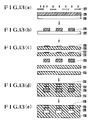
- Figs. 13(a) to 13(e) show a method of manufacturing the head of Figs. 12(a) and 12(b), for explaining the steps from ink channel pattern formation to sintering of the laminated body.
- the ink channel pattern is formed as follows.
- a photosensitive resin 226 is uniformly coated on a carrier film 225 such as a polyester film to form a resin layer having a predetermined thickness.
- the resin layer is exposed with light through a photomask having an ink channel pattern (Fig. 13(a)). Thereafter, the exposed resin pattern is developed to obtain a predetermined channel pattern 228 (Fig. 13(b)).
- a ceramic powder, an organic binder, and a plastisizer are mixed and dispersed in a solvent according to a known method to obtain a slurry.
- the slurry is coated on a plastic film, a glass plate, or a metal sheet by a doctor blade method or casting.
- the slurry layer is then dried and peeled from the plastic film, the glass plate or the metal sheet to obtain a ceramic green sheet.
- the ceramic green sheet is punched or cut to obtain a desired shape.
- a conductive paste is applied by screen printing onto the sheet having the desired shape, so that desired electrode and wiring patterns are formed in order to apply voltage thereto.
- an external electrode pattern 230 was formed on a first green sheet 229, and an internal electrode pattern 232 was formed on a second green sheet 231. Through holes are formed in the electrode connecting portions of the second green sheet.
- the channel pattern 228 is peeled from the carrier film 225.
- the channel pattern 228 is stacked together with the green sheets 229 and 231 with electrode patterns, and other green sheets 233 for forming ink channels (Fig. 13(c)) in a press mold such that cavities, electrodes, and other printed patterns are three-dimensionally arranged.
- the stacked sheets are pressed to obtain a laminated body so as to define the channel pattern 228.
- heat may be used under pressure (Fig. 13(d)).
- the laminated body may be cut into pieces as needed.
- the channel pattern resin material and the organic material contained in the ceramic green sheet are slowly heated in the oxygen atmosphere in the binder removing step to decompose and oxidize them.
- the organic material is normally completely decomposed and oxidized at a temperature of 500°C to 600°C. However, an abrupt temperature rise causes the damage to the laminated body. The rate of temperature rise is 25°C/hour or less.
- the laminated body is then kept at a temperature of 500°C to 600°C for a long period of time to completely remove the organic material.
- the ink channel pattern resin portions in the laminated body 235 constitute an ink channel pattern 236.
- the external and internal electrode patterns 230 and 232 are formed on and inside the laminated body.
- the laminated body is then sintered at a predetermined temperature to obtain a sintered body (Fig. 13(e)).
- the sintered body is cut into pieces of a predetermined size as needed, and the nozzle end face is cut to prepare
- a PbTiO3-PbZrO3 based powder was used as the ceramic powder in the fabrication process.
- a conductive paste having an Ag/Pd ratio of 70/30 (weight ratio) was used as the electrode material.
- a UV curable acrylic resin was used as the photosensitive resin for forming the ink channel pattern. The resin sheet was exposed with ultraviolet rays. Ethyl methyl ketone was used as a developing agent.
- the ceramic green sheet and the ink channel pattern were pressed at a pressure of 250 kg/cm2 and at a temperature of 110°C for 30 minutes.
- the lamination step was performed such that a rate of temperature rise was 5°C/hour in air, and the temperature was kept at 500°C for 3 hours to remove the organic material. Sintering was performed in air at 1,150°C for 2 hours.
- each green sheet was about 100 ⁇ m, and the thickness of the photosensitive resin was about 100 ⁇ m.
- the sectional size of the nozzle is about 80 ⁇ m x 80 ⁇ m.
- the height of other channels was 80 ⁇ m.
- a pulsed voltage of about 50 V was applied to the resultant head, and ink drops were found to be injected from the nozzles.
- Fig. 14 shows still another embodiment of the ink-jet head, showing a section at the pressure chamber.
- the pressure chamber walls are formed to be symmetrial about the plane B - B' of Fig. 14.
- Electrodes 239, 240, 241, and 242 driven upon reception of the drive voltage are formed to be symmetrical about the plane B - B' in the pressure chamber wall and on the outer surface thereof.
- Each electrode 239 is connected to the corresponding electrode 241, and each electrode 240 is connected to the corresponding electrode 242.
- These electrodes receive the external drive voltage.
- Upper and lower wall portions are deformed symmetrically about the plane B - B', and the ink is injected from the pressure chamber 238 and is sprayed from a corresponding nozzle (not shown) communicating therewith.
- vibrations accompanied by deformation of the wall of the pressure chamber are transmitted to a flat head plate 237 and then to other pressure chambers, thus interfering ink injection of other nozzles and generating large noise caused by vibrations of the flat plate 237.
- the electrodes are symmetrically arranged, the vibrations generated by the upper and lower walls are cancelled to each other because of their opposite phases. Therefore, vibrations are not substantially generated by the head plate 237.
- the vibration level could be reduced to 1/10 as compared with the case wherein the electrodes are arranged at one side with respect to the plane B - B'. Therefore, even if the thickness of the head is reduced, a compact head with the symmetrical electrode arrangement can be obtained at low vibration and noise levels.
- the wall is deformed at two locations, so that the size of the pressure chamber can be reduced into 1/2 as compared with the arrangement wherein the electrodes are arranged at one side with respect to the plane B - B'. If the size of the pressure chamber is kept unchanged, the level of the drive voltage can be reduced into 1/2.
- a method of manufacturing the head of Fig. 14 may be achieved such that green sheets 229 and 231 are reversely stacked in place of the green sheets 233 in Fig. 13(c).
- Figs. 15(a) and 15(b) are respectively a perspective view of still another embodiment of an ink-jet head according to the present invention, and a sectional view thereof taken along the line A - A' of Fig. 15(a).
- the head in Figs. 15(a) and 15(b) has a flat structure obtained by stacking and laminating ceramic plates of a piezoelectric or electrostrictive material.
- the head has pressure chambers 316 for applying a pressure to the ink upon ink injection in the same manner as in the conventional on-demand head.
- the pressure chambers 316 respectively communicate with nozzle apertures 311 through ink channels.
- Each pressure chamber has an ink inlet port connected to a common ink chamber communicating with an external ink tank.
- electrodes 312 and 318 are formed in the wall defining each pressure chamber 316 and on the outer surface of the wall.
- the shape of each electrode is substantially the same as that of the corresponding pressure chamber. In this case, the electrode is rectangular.
- Each internal electrode 318 is located substantially at the center of the wall along a direction of thickness thereof.
- Each internal electrode 318 is connected, through a wiring pattern embedded in the wall, to a corresponding terminal 314 via a corresponding through hole 317 formed in the wall.
- Each external electrode 312 is connected to a corresponding terminal 313 through a corresponding wiring pattern.
- Elongated grooves 315 are formed at both sides of each electrode 312.
- Each groove 315 has at least a depth corresponding to the level of the corresponding electrode 318.
- the depth of the groove 315 is not restricted to the one described above.
- two grooves are formed at both sides of each of the electrodes corresponding to the plurality of pressure chambers.
- the adjacent grooves between the adjacent electrodes may be replaced with a single groove to obtain the same effect as described above.
- a drive voltage is applied to the terminals 313 and 314.
- the polarities of the drive voltage are determined such that a layer sandwiched between the electrodes 312 and 318 stretches or shrinks by the effect of the electric field.
- the stress occurs to cause the layer sandwiched between the electrode 312 and 318 to stretch or shrink. Since this portion is separated from other wall portions by the grooves formed at both sides of the corresponding electrode 312, the portion does not receive any external force which prevents stretch or shrinkage. Therefore, this portion can be effectively deformed as a bimorph element.
- an identical deformation magnitude can be obtained by a small voltage amplitude.
- the internal stress of the wall is reduced to remove the damage to the wall caused by the stress exceeding the elastic limits of the wall and the damage to the wall caused by the fatigue.
- Figs. 16(a) to 16(f) show the steps in manufacturing the ink-jet head of Figs. 15(a) and 15(b).
- PbTiO3-PbZrO3 based ceramic green sheets were used as a ceramic material to constitute a head body. The thickness of each green sheet was about 100 ⁇ m. A silver paste was used as the electrode material.
- the green sheet is cut into pieces of a predetermined shape.
- the steps from ink channel pattern formation to sintering are illustrated in Figs. 16(a) to 16(f).
- a photosensitive resin 422 is applied to a carrier film 421 such as a polyester film to form a resin layer having a predetermined thickness.
- a photomask 420 having the ink channel pattern is brought into contact with the resin layer, and the resin layer is exposed with light through the photomask 420 (Figs. 16(a)). Thereafter, the exposed resin layer is developed to obtain a predetermined channel pattern 423 (Fig. 16(b)).
- Electrode and wiring patterns for receiving a drive voltage are formed on green sheets by screen printing.
- an external electrode pattern 425 is formed on a first green sheet 424
- an internal electrode pattern 427 is formed on a second green sheet 426.
- Through holes are formed in the first green sheet so as to connect the internal electrode pattern to an external wiring when the green sheets are stacked.
- the green sheet 424 with the electrode pattern and the through hole pattern, the green sheet 426 having the electrode pattern, other green sheets 428, and the ink channel pattern 423 peeled from the carrier film are stacked in a mold such that the cavities, the electrodes, and other printed patterns are three-dimensionally formed (Fig. 16(c)).
- the stacked individual sheets are pressed to constitute a laminated body so as to surround the ink channel pattern 423.
- Grooves 429 are formed by a cutter between the electrodes on the laminated body 430 (Fig. 16(e)).
- the depth of each groove substantially corresponds to the thickness of the first green sheet 424.
- the grooves are formed up to the depth corresponding to the level of the internal electrodes 427.
- the resultant laminated body is cut into pieces of a predetermined size.
- the ink channel pattern resin 423 and the organic material in the laminated body are removed in the binder removing step by slowly heating the laminated body in an oxygen atmosphere, so that the organic material is decomposed and oxidized. In this case, an abrupt temperature rise causes the damage to the laminated body. Therefore, the laminated body is preferably heated at a rate of 25°C/hour and is kept at a temperature of 500°C to 600°C for a long period of time, thereby completely removing the organic material. After this process, no resin is left in the laminated body 430, and thus cavities 431 corresponding to the ink channel pattern are formed.
- the electrode patterns 425 and 427 are formed on the outer surface of the laminated body and inside the laminated body, respectively.
- This laminated body is sintered in air at about 1,150°C for 2 hours to obtain a sintered body (Fig. 16(f)).
- the sintered body is cut at a portion corresponding to the nozzle end face.
- the nozzle end face is then polished to achieve stable ink drop injection.
- the green sheets are stacked and pressed to obtain the laminated body, and the grooves are formed in the laminated body.
- the grooves need not be formed in the laminated body, but may be formed in the sintered body to obtain the same ink-jet head as described above.
- Figs. 17(a) to 17(e) are sectional views showing other steps in manufacturing the ink-jet head of Figs. 15(a) and 15(b). According to this method, groove formation is simultaneously performed with stacking and pressing, thereby simplifying the fabrication process.
- a photosensitive resin is used to form an ink channel pattern 523, and electrodes 525 and 527 and wiring patterns are formed on green sheets 524 and 526 in the same manner as in the steps of Figs. 16(a) and 16(b) (Figs. 17(a) and 17(b)).
- a mold 532 used for stacking has projections 533 corresponding to the grooves to be formed between the electrodes 525.
- the first green sheet 524, the second green sheet 526, the channel pattern 523, and other green sheets 528 are stacked such that cavities, electrodes and the like are three-dimensionally arranged (Fig. 17(c)), and the stacked sheets are pressed to obtain a laminated body (Fig. 17(d)).
- the green sheets are deformed to fill the gaps therebetween and are brought into tight contact with each other to constitute the laminated body. In this case, heat may be applied under pressure. Therefore, lamination of the green sheets can be simultaneously performed with groove formation.
- the laminated body 535 is cut into pieces as needed, the resin and organic material are removed in the binder removing step, and the laminated body is sintered and converted into a sintered body in the same manner as in Fig. 16(f) (Fig. 17(e)).
- Figs. 18(a) and 18(b) are sectional views showing stacking and pressing steps according to still another embodiment of a method of manufacturing the ink-jet head of Figs. 15(a) and 15(b).
- deformation of grooves is improved when the laminated body is released from the mold with projections used in Figs. 17(c) and 17(d).
- a groove pattern 640 is formed between the electrodes by using a photosensitive resin for forming an ink channel pattern.
- a groove pattern 640, green sheets 624 and 625 having electrode and wiring patterns, an ink channel pattern 623, and other green sheets 628 are stacked in a mold 641 such that grooves, cavities, and electrodes are three-dimensionally arranged.
- the stacked sheets and patterns are pressed to obtain a laminated body.
- the groove pattern 640 is embedded into the corresponding green sheet.
- the laminated body 642 is heated in an oxygen atmosphere in the binder removing step to decompose and oxidize the organic material such as a resin. Therefore, the ink channel pattern and the grooves are formed.
- the groove pattern is formed by using the photosensitive resin.
- the process for forming the groove pattern is not limited to this method.
- grooves may be formed by a plastic film punched so as to have a groove pattern shape.
- Fig. 19 is a perspective view showing still another embodiment of a ceramic ink-jet head according to the present invention.
- An ink is supplied to a connecting port 705 from an ink fountain through an ink pipe.
- the ink is sprayed outside from each nozzle 703 through a common ink chamber 704, a corresponding ink supply port 701, and a corresponding pressure chamber 702.
- the ink passage from the common ink chamber 704 to the respective nozzles 703 is constituted by four parallel channels to constitute a 4-nozzle head.
- the number of nozzles is arbitrarily determined to satisfy a desired recording speed.
- the members excluding the electrodes are made of a ceramic material having electromechanical transducer characteristics. Fig.
- each pressure chamber 702 comprises a plurality of ceramic layers 706 (four layers in this case).
- the number of layers is not limited to four, but may be arbitrarily determined according to the thickness of each layer and the electrode area. Electrodes are formed on the upper surface of each ceramic layer 706.
- the electrodes of each layer comprise driving electrodes 707 and wiring electrodes for connecting the driving electrodes to a drive circuit (not shown).
- the patterns of the driving electrodes 707 on the surfaces of the ceramic layers 706 are identical and vertically stacked. However, the pattern of the wiring electrodes of the odd-numbered layer in Fig. 20(a) is different from that of the even-numbered layer in Fig. 20(b). More specifically, the electrode patterns of the first and third layers counted from the side near the corresponding pressure chamber are arranged such that the driving electrodes 707 are commonly connected to a wiring electrode 709 through wiring electrodes 709, and the wiring electrode 709 is connected to the drive circuit, as shown in Fig. 20(a). The electrode patterns of the second and fourth layers are arranged such that the driving electrodes 707 are respectively connected to wiring electrodes 710 which are then connected to the drive circuit, as shown in Fig. 20(b).
- the electrode patterns in Figs. 20(a) and 20(b) are alternately stacked in the vertical direction, as shown in Fig. 21.
- the corresponding electrodes 710 of the odd-numbered layers are connected to each other at terminals 712, and the corresponding electrodes 709 of the even-numbered layers are connected to each other at a terminal 711.
- the connections of the electrodes are performed along the stacking direction as follows.
- Through holes 713 are formed at the centers of the terminals 711 and 712 so as to extend through the ceramic layers. Before or after the laminated body of the ceramic layers is sintered, a conductive paste is filled in the through holes to achieve electrical connections.
- the ceramic layers between the electrodes must be polarized in advance. This polarization is performed in the same manner as in the conventional laminated actuator.
- a predetermined high voltage is applied between the electrode terminals 711 and 712 for a short period of time.
- the ceramic portion sandwiched between the driving electrodes 707 is polarized along a direction perpendicular to the surface of the electrode. The polarization directions of each adjacent electrodes are opposite.
- Figs. 22(a) to 22(e) show a method of manufacturing the ink-jet head, explaining steps from the cavity pattern formation for the ink channel pattern to sintering of the laminated body.
- the cavity pattern is formed as follows.
- a photosensitive resin 715 is uniformly applied to a carrier film 714 such as a polyester film to form a resin layer having a predetermined thickness.
- a photomask 717 having the same pattern as the ink channel pattern is brought into contact with a photosensitive resin sheet 716, and the sheet 716 is then exposed with light.
- the exposed sheet is developed to obtain a predetermined cavity pattern 718.
- the ceramic green sheets are stacked such that the cavity pattern 718 is sandwiched therebetween.
- the ceramic green sheet is prepared as follows. A ceramic powder, an organic binder, a plastisizer, and the like are mixed and dispersed in a solvent according to a known method to prepare a slurry. The slurry is applied to a substrate such as a plastic film, a glass plate, or a metal sheet by a known coating method such as a doctor blade method and casting to form a slurry layer having a predetermined thickness. The slurry layer is then dried, and the dried layer is peeled from the substrate to obtain a ceramic green sheet. Thereafter, the ceramic green sheet is cut or punched to obtain a predetermined shape.
- through holes are formed in the green sheet by punching, and a conductive paste is screen-printed to form a surface electrode pattern.
- a conductive paste is screen-printed to form a surface electrode pattern.
- two green sheets 720a having an identical electrode pattern 719a and two green sheets 720b having an identical electrode pattern 719b are alternately stacked, i.e., serve as the second and fourth layers and the first and third layers.
- Through holes 713 are formed at centers of electrode terminals 711 and 712 in the green sheets having the surface electrode patterns, as shown in Fig. 21.
- green sheets 721 do not have surface electrode patterns or through holes, but have the same outer dimensions as those of the green sheets 720a and 720b. These green sheets 720a, 720b, and 721 are stacked together with the cavity pattern 718 peeled from the carrier film in a press mold according to a predetermined order. The stacked sheets are pressed to obtain a laminated body 722, as shown in Fig. 22(d). In the pressing step, heat may be applied under pressure. The green sheets are partially deformed to completely surround the cavity pattern, thereby obtaining a laminated body 722.
- the resultant laminated body 722 is cut into pieces of a predetermined shape and is subjected to removing of binder.
- the laminated body is slowly heated in the oxygen atmosphere to decompose and remove the resin constituting the cavity pattern and the organic material contained in the ceramic green sheets.
- the organic material is normally completely decomposed and oxidized at a temperature of 500°C to 600°C.
- an abrupt temperature rise causes the damage to the laminated body.
- the rate of temperature rise is 25°C/hour or less, and the temperature is kept at 500°C to 600°C for a long period of time to completely remove the organic material.
- the cavity pattern 718 in the laminated body 722 is removed, and thus cavities are left to constitute ink channels.
- the binder When the binder is removed from the laminated body 722, it is then sintered at a predetermined temperature to obtain a sintered body 723 as shown in Fig. 22(e). Thereafter, the sintered body is cut into pieces of a predetermined size, and the nozzle end face is polished to prepare an ink-jet head.
- a PbTiO3-PbZrO3 based piezoelectric material was used as a ceramic powder constituting the green sheet.
- a conductive paste having an Ag/Pd ratio of 70/30 (weight ratio) was used as the electrode material.
- a UV curable acrylic resin was used as a photosensitive resin for forming the cavity pattern. After the resin was exposed with ultraviolet rays, it was developed by methyl ethyl ketone.
- the ceramic green sheets and the cavity pattern were pressed at a pressure of 250 kg/cm2 and at a temperature of 110°C for 30 minutes.
- the binder was removed such that the laminated body was heated in air at a temperature rise rate of 5°C/hour. After the laminated body was heated to 500°C and kept thereat for 3 hours. Sintering was performed at 1,150°C for 2 hours.
- each green sheet and the photosensitive resin pattern was about 100 ⁇ m.
- the sectional size of the nozzle is about 80 ⁇ m x 80 ⁇ m.
- the height of the channel inside the sintered body was about 80 ⁇ m.
- An experimental head of Fig. 19 was prepared under the above conditions, and stable ink ejection can be achieved.
- the pulse voltage amplitude was controlled such that the volumes of the ink drops and ejection speeds thereof became identical. Variations in voltage fell within the range of 34 V to 37 V. Therefore, it was found that the uniform ejection characteristics of the nozzles could be obtained.
- a two-layer ink-jet head i.e., the number of layers is reduced to 1/2 as compared with the head of Fig. 19
- an application voltage greatly varied from 55 V to 70 V.
- the method of the present invention provides a ceramic ink-jet head incorporating a laminated actuator having a large number of electromechanical transducer elements along the direction of thickness.
- a laminated actuator is built into as an individual component
- the positional precision of the laminated actuator can be improved to provide an ink-jet head having good and uniform ejection characteristics.
- the fabrication techniques do not require skills, and the head can be easily manufactured in a mass production line.
- the device cost can be greatly reduced.
- the use of the laminated actuator greatly reduces the drive voltage, and a simple drive circuit can be used with high reliability, thereby further reducing the cost.
Description
- The present invention relates to a ceramic electronic device and a method of manufacturing the same.
- In order to form cavities in ceramic electronic devices according to conventional methods, a paste such as a carbon paste to be decomposed and removed at a temperature up to a ceramic sintering temperature is coated in ceramic plates, or a press plate is compressed on a ceramic green sheet. For example, in order to prepare a conventional laminated ceramic capacitor, a paste containing carbon is coated on a green sheet, and sheets including the sheet with a paste layer were stacked, pressed and sintered to form cavities at the paste portions. Thereafter, a metal such as silver, lead or tin is impregnated in the cavities under pressure to form internal electrodes (Fabrication of Multilayer Ceramic Capacitors by Metal Impregnation; IEEE TRANSACTION ON PARTS, HYBRIDS, AND PACKAGING, VOL. PHP-9, No. 3 SEPT. 1973, pp. 144 - 147).
- The first drawback of a piezoelectric electroacoustic transducer device prepared by conventional techniques lies in the fact that a piezoelectric plate, an elastic plate, and a casing are separately prepared and are finally assembled together. In order to assemble such devices in the mass production line, a large number of assembly steps are required. Even if an automated assembly system is used, a considerably high investment capital is required, thus increasing the product cost.
- The second drawback of the piezoelectric electroacoustic transducer device is degradation of the performance and reliability caused by adhering the piezoelectric and elastic plates by an adhesive or the like. If a bending resonator is flexed upon reception of an electrical signal or an external sound pressure, a large stress is concentrated in the adhesion layer portion. If the transducer is driven at a large amplitude for a long period of time, the adhesion layer is damaged. In addition, vibration energy is absorbed in the adhesion layer to degrade operational efficiency. Furthermore, the temperature characteristics of the transducer are degraded by an influence of the adhesive.
- The third drawback of the piezoelectric electroacoustic transducer device is the limitations of a decrease in thickness of the piezoelectric plate. The resonant frequency of the bending resonator is proportional to its thickness and is in inverse proportion to the square of its diameter. In order to obtain a compact transducer device usable in a low frequency, the thickness of the piezoelectric plate must be minimized. In the process for preparing a thin piezoelectric plate, its thickness is limited, as described above. Even if a thin piezoelectric plate is prepared, it is mechanically damaged when it is adhered to the elastic plate. Therefore, as compared with the case wherein a piezoelectric plate having a relatively large thickness is used, the yield of the piezoelectric plates is greatly decreased.
- The fourth drawback of the piezoelectric electroacoustic transducer device is to require fine finish for forming a flat surface of the piezoelectric plate. Upon adhesion of the piezoelectric plate to the elastic plate, if the piezoelectric plate is warped or has a large recess, the plate is damaged and the contact density of the piezoelectric plate adhered to the elastic plate is undesirably decreased. Furthermore, incomplete adhesion also leads to the degradation of energy conversion efficiency of the bending resonator.
- In a conventional ink-jet head, a metal press plate is pressed on a green sheet or an acrylic die is set in a green sheet, thereby forming cavities (Japanese Patent Prepublication No. 58-87060).
- However, according to the conventional cavity or space formation method, satisfactory precision cannot be obtained, or the height of the cavity is undesirably small. In order to form a cavity pattern by screen printing such that a carbon paste to be decomposed and removed at a high temperature is coated on the green sheet, the minimum order is restricted to the formation of a micropattern having a width of 100 µm at a pitch of 200 µm. In this case, the pattern has only a maximum height of 10 µm. Therefore, the resultant cavity is not enough to be used as a cavity for electronic device.
- In the conventional case of forming cavities by using a metal press plate or a plastic film press plate, deformation under pressure results in degradation of precision of the pattern.
- In particular, if a recess is formed on the green sheet under pressure by using a metal press plate, a ceramic sheet serving as a cover member is stacked thereon and thermally pressed. In this case, part of the overlying green sheet is undesirably inserted in the recess to cause irregular depths of the cavities.
- Even if an acrylic sheet is used as a press plate and inserted in the green sheet, the acrylic sheet is deformed, thus degrading the dimensional precision.
- In general, the ceramic electronic devices are operated through electrodes. According to a conventional preparation method, it is difficult to form an electrode inside the ceramic body or at a surface portion defining the cavity formed therein. According to the conventional method, after the ceramic sheet is sintered, a thick film is printed or plated to form electrodes on the resultant structure.
- According to this method, the electrodes are formed on only the surface of the resultant structure. The use of a piezoelectric ceramic material limits a variety of applications. As a result, it is very difficult to prepare high-performance electronic devices.
- In an ink-jet head described in Japanese Patent Prepublication No. 58-87060, ink ejection members such as an ink supply member, an ink channel groove, and an nozzle are made of a ceramic material. In this head, a metal press plate is compressed on a green sheet to form grooves. An acrylic die is pressed and inserted in the green sheet, and another ceramic green sheet serving as a cover member is placed thereon. The stacked sheets are then pressed and sintered. After sintering, a means for generating or applying mechanical vibrations is formed on the upper surface of the sintered body. As shown in Fig. 2, a piezoelectric sheet is used as an
upper cover member 010 and sintered. After sintering, drivingelectrodes upper cover member 010. - By using this ceramic body, the
upper cover member 010 can be easily adhered to aplate 009 with ink channel grooves. However, the conventional head does not have high precision of ink channels. The nozzle tip is not maintained in the top condition so that the ink ejection is warped. - Grooves for the ink channels are formed by etching, as shown in Figs. 1(a) and 1(b). In this case, the etching precision has limitations. Variations in nozzle diameter greatly degrading the ink injection characteristics are undesirably increased. In the head structure of Figs. 1(a) and 1(b), nozzle apertures are constituted by stacking a
cover plate 006 on abase plate 001. If misalignment between theplates plates base plate 001 is bonded to thecover plate 006, the edge of the nozzle portion is cut or polished to eliminate a step on the adhesion end face. In this case, if a metal material is used to constitute theplates 110 and 006, burrs are inserted in the nozzles by cutting and polishing. Many problems are left unsolved in order to obtain a flat nozzle end face. - When a conventional ceramic material is used, as shown in Fig. 2, it is difficult to form the ink channels with high precision using metal and plastic press plates since the ceramic material is deformed under pressure. In particular, when recesses are formed in the green sheet by using a metal plate, the green sheet serving as the cover member is partially inserted in the recesses under pressure to result in irregular depths of cavities, i.e., the ink channels. Furthermore, even if an acrylic sheet is used and pressed into the green sheet, a large pressure is required to embed the entire acrylic sheet, and the sheet is inevitably deformed to degrade the precision of ink channels.
- According to a conventional method, electrodes are formed by printing a thick conductive paste film on the surface after the ceramic material is sintered. The
electrodes 012 in Fig. 2 are formed by this method. In order to apply a voltage to this head,corresponding electrodes 013 are required. Theseelectrodes 013 are formed on the inner wall surfaces definingcorresponding pressure chambers 011. These electrodes can be formed by electroless plating. With this electrode structure, the wall sandwiched by the electrodes stretches or shrinks upon application of the voltage across the electrodes. Therefore, the wall does not substantially generate a force for ejecting the ink from the pressure chambers. If any, the force is not stable due to bending deformation of the wall. According to the conventional method, therefore, since the electrodes are formed only on the both sides of the pressure chamber wall portions, a sufficient pressure cannot be effectively generated. - It is an object of the present invention to solve the conventional problems described above, form microcavities in a ceramic body with high precision, and at the same time form electrodes therein, thereby providing a high-performance electronic device.
- It is another object of the present invention to address the problems described above and to provide a method of manufacturing a high-performance piezoelectric electroacoustic transducer device which is compact and lightweight and has a high yield with good reproducibility at low cost in a mass production line.
- It is still another object of the present invention to address the conventional problems described above and to provide a high-performance ink-jet head wherein ink channels are formed in a ceramic body with high precision and at the same time electrodes can be formed inside the ceramic body.
- According to an aspect of the present invention, there is provided a method of manufacturing a ceramic electronic device containing cavities, characterised by including the steps of: forming a pattern of a predetermined shape to define said cavities using a material to be removed upon heating thereof to a temperature not higher than a sintering temperature of a ceramic material; forming an electrical circuit element in a ceramic green sheet; stacking and compressing together said pattern, said ceramic green sheet having said electrical circuit element, and at least another ceramic green sheet to obtain a laminated body heating the laminated body to remove this pattern material and sintering said laminated body to obtain a sintered body.
- According to another aspect of the present invention, there is provided a ceramic electronic device device comprising a cavity and an electrical circuit element formed in a ceramic body, and characterised in that the ceramic body is of the same material throughout and does not contains layers of adhesives.
- Figs. 1(a) and 1(b) are perspective views showing a conventional ceramic electronic device;
- Fig. 2 is a sectional view showing another conventional ceramic electronic device;
- Fig. 3A shows a fabrication process of an embodiment of a method of manufacturing a ceramic electronic device according to the present invention;
- Figs. 3B(a) to 3B(f) are sectional views for explaining the steps in the fabrication process of Fig. 3A;
- Fig. 4A shows a fabrication process of another embodiment of a method of manufacturing a ceramic electronic device according to the present invention;
- Figs. 4B(a) to 4B(g) are sectional views for explaining the steps in the fabrication process of Fig. 4A;
- Fig. 5 is a sectional view showing an embodiment of a ceramic electronic device according to the present invention;
- Fig. 6 is a sectional view showing another embodiment of a ceramic electronic device according to the present invention;
- Fig. 7 is a view showing planar and sectional structures of still another embodiment of a ceramic electronic device according to the present invention;
- Fig. 8 is a view showing planar and sectional structures of still another embodiment of a ceramic electronic device according to the present invention;
- Figs. 9(a) and 9(b) are respectively a plan view and a sectional view of still another embodiment of a ceramic electronic device according to the present invention;
- Figs. 10(a) and 10(b) are respectively a plan view and a sectional view of still another embodiment of a ceramic electronic device according to the present invention;
- Figs. 11(a) and 11(b) are respectively a plan view and a sectional view of still another embodiment of a ceramic electronic device according to the present invention;
- Figs. 12(a) and 12(b) are respectively a partially cutaway perspective view and a sectional view of still another embodiment of a ceramic electronic device according to the present invention;
- Figs. 13(a) to 13(e) are sectional views for explaining the steps in manufacturing the device of Figs. 12(a) and 12(b);
- Fig. 14 is a sectional view showing still another embodiment of a ceramic electronic device according to the present invention;
- Figs. 15(a) and 15(b) are respectively a perspective view and a sectional view of still another embodiment of a ceramic electronic device according to the present invention;
- Figs. 16(a) to 16(f) are sectional views for explaining the steps in manufacturing the ceramic electronic device in Figs. 15(a) and 15(b);
- Figs. 17(a) to 17(e) are sectional views for explaining other steps in manufacturing the ceramic electronic device in Figs. 15(a) and 15(b);
- Figs. 18(a) and 18(b) are sectional views for explaining still other steps in manufacturing the ceramic electronic device in Figs. 15(a) and 15(b);
- Fig. 19 is a partially cutaway perspective view showing still another embodiment of a ceramic electronic device according to the present invention;
- Figs. 20(a) and 20(b) are perspective views showing the electrode patterns in the embodiment of Fig. 19;
- Fig. 21 is a perspective view showing the electrode connections in the embodiment of Fig. 19; and
- Figs. 22(a) to 22(e) are sectional views for explaining the steps in manufacturing the ceramic electronic device in Fig. 19.
- Preferred embodiments of ceramic electronic devices and its fabrication methods according to the present invention will be described with reference to the accompanying drawings.
- Fig. 3A and Figs. 3B(a) to 3B(f) show the process for manufacturing a ceramic electronic device. A
photosensitive resin 1 is coated on acarrier film 2 such as a polyester film to form a resin sheet having a predetermined thickness. A photomask 3 having a predetermined pattern is brought into contact with the resin sheet, and the resin sheet is exposed with light. The exposed resin sheet is then developed to form apredetermined cavity pattern 4. A ceramicgreen sheet 5 is prepared in the following manner. A ceramic powder, an organic binder, and a plastisizer are mixed and dispersed in a solvent to obtain a slurry according to a known method. The slurry is applied to a plastic film, a glass plate, or a metal sheet by a doctor blade method or casting, and is dried to prepare the ceramicgreen sheet 5. - The ceramic green sheet is peeled from the film or plate after the sheet is dried. The resultant ceramic green sheet is punched or cut to obtain a predetermined size. Through holes are formed in the resultant green sheet by punching or the like, and an
electrode paste 6, a resistive paste, or a dielectric paste is printed on the surface of the ceramic green sheet. - The
cavity pattern 4 is peeled from thecarrier film 2 and placed together with the ceramicgreen sheet 5 in a press mold such that the cavities, electrodes and other patterns are three-dimensionally arranged. The stacked body is compressed to obtain a laminated body. In this case, heat may be applied under pressure, as needed. - A resultant
laminated body 7 is cut into portions of a predetermined size. An organic material contained in the cavity pattern and the ceramic green sheets is gradually heated, decomposed, and oxidized in an oxygen atmosphere in the binder removing step. In this case, such an organic material is normally completely decomposed and oxidized when it is heated to a temperature of 500°C to 600°C. However, if a temperature rise is abrupt, thelaminated body 7 itself is damaged. The rate of temperature rise is 25°C/hour or less, and the temperature is kept at 500°C to 600°C for a long period of time, so that the organic material is completely removed. - After the binder removing step is completed, no organic material is left in the laminated body. The cavity pattern is left as
cavities 9 in the laminated body. The laminated body is then sintered at a predetermined temperature to obtain aceramic body 10. Theceramic body 10 is cut into pieces of a predetermined size, as needed, thereby obtaining ceramic electronic devices. - Fig. 4A and Figs. 4B(a) to 4B(g) show another embodiment of a method of manufacturing a ceramic electronic device according to the present invention. The method in Fig. 4A and Figs. 4B(a) to 4B(g) differs from that in Fig. 3A and Figs. 3B(a) to 3B(f) in the following points.
- A ceramic paste having the same powder and the same binder composition as those of the ceramic green sheet described above, or a slurry obtained by dispersing a ceramic powder in a solvent is applied by screen printing or casting to a
cavity pattern 4 formed on acarrier film 2. The resultant ceramic layer is dried to obtain a ceramic sheet. - According to this method, a
green sheet 5 with the cavity pattern being embedded therein is formed. - The
green sheet 5 with thecavity pattern 4 is punched to obtain a sheet of a predetermined size. The resultant green sheet is stacked together with other green sheets in a mold such that cavities, electrodes, and other printed patterns are three-dimensionally arranged. The stacked sheets are compressed to obtain a laminated body. In this process, heat may be applied under pressure, as needed. - In the above methods, it is important to use a photosensitive resin to obtain a microcavity pattern with high precision. It is also important to prepare a ceramic green sheet with a cavity pattern, laminate it with another ceramic green sheet with spaces corresponding to the cavity pattern, and press a laminated body, unlike in the case wherein the cavity pattern is embedded in the ceramic sheet under pressure.
- Examples of the photosensitive resin are photocurable acrylic resin, nylon resin, epoxy resin, polyurethane resin, and polybutadiene resin. The pressing temperature is a glass transition temperature of a binder resin used in the green sheet. A small amount of solvent may be sprayed onto the green sheet prior to pressing.
- Since the cavity pattern is made of a photosensitive resin, a micropattern can be formed with high precision.
- When a photosensitive resin is used, patterns each having a width of 10 µm may be easily formed at pitches of 20 µm according to current patterning techniques. In addition, the height of the cavity can be increased to a maximum of several millimeters. Therefore, an aspect ratio as the ratio of width to thickness of the pattern can be 1 or more.
- In the cavity or space formation process, if the cavity pattern is embedded into the green sheet under pressure, as in the conventional technique, the depth of the cavity pattern is limited to up to about several microns. Furthermore, in order to deeply embed the cavity pattern in the green sheet, a high pressure is required, thus causing deformation of the cavity pattern and hence resulting in precision degradation.
- However, according to the method of the present invention, the photosensitive resin is exposed with light through a photomask. A ceramic paste having the same binder composition as that of the ceramic sheet or a slurry is applied to the developed cavity pattern by screen printing or casting (e.g., the doctor blade method). The applied paste or slurry is dried to fill the recesses defined by the cavity pattern, thereby obtaining a flat surface of the cavity pattern.
- In the subsequent step, i.e., laminating and pressing, a uniform pressure is applied to the cavity pattern to greatly decrease the deformation of the cavity pattern and to improve the dimensional precision of cavities.
- Furthermore, electrodes are formed on the surfaces of the ceramic green sheets to form electrodes inside the sintered ceramic body, on ceramic inner walls defining the cavities, and on outer surface of the ceramic body. By forming the through holes in the ceramic green sheets, the electrodes formed on the surface of the cavity pattern, inside the ceramic body, and on the outer surface of the ceramic body can be three-dimensionally wired.
- In addition to metal conductors, a resistor green sheet, a dielectric green sheet, and a ceramic green sheet with an electrode the material of which is different from the-metal conductors described above may be expected to be connected so as to provide a structure having electronic and electric functions.
- Fig. 5 shows an embodiment of a piezoelectric electroacoustic transducer device. Referring to Fig. 5, a sound wave transmitting/receiving
piezoelectric plate 11,electrodes 12 and 12', anelastic plate 13, and acase 15 are integrally formed with each other. Other portions excluding the electrodes are made of a piezoelectric ceramic material. In the sound wave transmission mode, an AC electrical signal is supplied betweenelectrode terminals 14 and 14'. Thepiezoelectric plate 11 sandwiched between theelectrodes 12 and 12' stretches or shrinks along the horizontal direction by a piezoelectric effect. However, since thepiezoelectric plate 11 is bonded to theelastic plate 13 which is piezoelectrically inactive, an integral body constituted by thepiezoelectric plate 11, theelectrodes 12 and 12', and theelastic plate 13 is bent upward or downward. In this manner, the input electrical signal is transduced into acoustic energy, so that a sound is produced outside through through holes 16 formed in the upper wall of thecase 15. - The sound wave transmitting/receiving
plate 11 is simultaneously integrally formed with the case, and no adhesive is used to prepare such an integral body. Therefore, all drawbacks of the devices manufactured by the conventional methods can be eliminated. - Fig. 6 shows another electroacoustic piezoelectric transducer according to the present invention. In this embodiment, a
piezoelectric plate 21 is sandwiched betweenmetal electrodes metal electrode 23 also serves as an elastic plate. A metal has a higher bending strength than a piezoelectric ceramic material. It is therefore possible to increase the mechanical strength of the sound wave transmitting/receiving plate as compared with the construction of Fig. 5. - An embodiment of a piezoelectric ceramic resonator prepared by the method of the present invention will be described with reference to Fig. 7.
- Fig. 7 shows an embodiment of the ceramic resonator according to the present invention. Referring to Fig. 7,
metal electrode films 32 and 32' are formed on the upper and lower surfaces of a ceramic piezoelectric resonant plate 31 at the center thereof. Themetal electrode films 32 and 32' are connected toexternal pads 34 and 34' through electrode leads 33 and 33', respectively. Thecavities 35 and 35' are formed to allow free resonance of the resonant plate 31. The resonant plate 31 is disposed in aprotective case 36 made of the same material as the resonant plate 31. Since theprotective case 36 is integrally formed with the resonant plate 31 in the piezoelectric resonator having the construction described above, a separate protective case and a molding resin for protecting the resonator need not be used. In addition, assembly and molding are eliminated. Since the resonant plate, the electrodes and the protective case are simultaneously integrally formed by tape casting to prepare the resonator shown in Fig. 7, it is suitably manufactured in a mass production line. Therefore, the fabrication cost can be greatly reduced. - Fig. 8 shows another embodiment of a ceramic resonator according to the present invention. Referring to Fig. 8, the electrode film formed on the upper surface of a resonant plate 41 is divided into
electrode films 42 and 42'. Thefilms 42 and 42' are connected to external electrode pads 46 and 46' through electrode leads 44 and 44', respectively. Anelectrode film 43 is formed on the lower surface of the resonant plate and is connected to an external electrode pad 46' through anelectrode lead 45, thereby constituting a 3-terminal filter. The resonator in Fig. 7 is a single mode resonator, while the resonator in Fig. 8 is a double mode filter. - Figs. 9(a) and 9(b) are respectively a plan view and a sectional view of an on-demand ink-jet head with integral electrodes. In the on-demand ink-jet head, a piezoelectric
ceramic body 51 comprised a PbTiO₃-PbZrO₃ based ceramic material.Electrodes 52 were made of an electrode paste having an Ag/Pd ratio of 70/30 (mass ratio). A photosensitive resin for forming a cavity pattern was an UV curable acrylic resin to be cured with ultraviolet rays, and the exposed resin was developed by methyl ethyl ketone. - The ceramic green sheet and the green sheet with the cavity pattern embedded therein were pressed at a pressure of 250 kg/cm² and at a temperature of 110°C for 30 minutes.
- The laminated body was heated in air at a rate of temperature rise being 5°C/hour. The laminated body was kept at 500°C for 3 hours to decompose and oxidize the organic material. Sintering of the laminated body was performed in air at 1,150°C for 2 hours.
- An AC voltage of 40 V was applied to the electrodes of the resultant ink-jet head, the electrode formation portion was vibrated by the piezoelectric effect. In this case, ink drops were ejected from a
nozzle 53. The nozzle cross-section had a rectangular shape with each side of 100 µm. A cavity at apressure chamber 54 had a height of 100 µm and a maximum width of 5 mm. - Figs. 10(a) and 10(b) are respectively a plan view and a sectional view of another on-demand ink-jet head according to the present invention. In this head, a powder mixture of lead borosilicate glass and alumina was used a material for an insulating
ceramic body 65. A paste forconductive films 66 had an Ag/Pd ratio of 85/15 (weight ratio). A photosensitive resin for a cavity pattern was a UV curable nylon resin to be cured with ultraviolet rays. The exposed resin pattern was developed by an alkali. The ceramic green sheet and the green sheet with the cavity pattern contained therein are pressed at a pressure of 300 kg/cm² at a temperature of 80°C. Heater resistors 69 for generating bubbles were formed by a ruthenium oxide paste. After the organic material was decomposed at a temperature of 500°C, and the laminated body was sintered at 900°C for 2 hours. - An ink is filled in an
ink fountain 68, and an RF pulse is applied to theresistors 69 in the ink-jet head. In this case, the ink was found to be injected from anozzle 67. The opening size of thenozzle 67 was 50 µm x 50 µm. - Figs. 11(a) and 11(b) are respectively a plan view and a sectional view of a piezoelectric sound generator.
- A PbTiO₃-PbZrO₃ based piezoelectric material was used as a material for a piezoelectric body 61, and platinum was used as an electrode material.
- A 500-µm thick epoxy-based material was used as the photosensitive resin for forming a cavity pattern.
Air chambers 74 were formed in the interior of the sound generator through a driving portion (including electrodes 71) of the piezoelectric ceramic body 61. Theair chambers 74 communicated with an outer atmosphere throughcavities 73.Electrodes 72 were arranged in the ceramic body 61. After a laminated body was sintered to obtain the ceramic body 61, an AC voltage was applied between theelectrodes 72 to produce a 1-kHz sound. In this case, portions of the case above and below the resonator are constructed to produce sound through the cavities since the cavities are formed in the corresponding portions of the green sheets. - Various types of on-demand ink-jet heads and their manufacturing methods will be described with reference to other embodiments below.
- Figs. 12(a) and 12(b) show an on-demand ink-jet head according to the present invention, in which Fig. 12(a) is a partially cutaway perspective view thereof, and Fig. 12(b) is a sectional view of the ink-jet head of Fig. 12(a) taken along the line A - A' thereof.
- In this head, a
ceramic substrate 80 made of a piezoelectric or electrostrictive material, an upper cover(I) 85, and an upper cover (II) 87 are stacked together. In this case, the contact portions between thesubstrate 80 and the upper cover(I) 85 and between the upper cover(I) and the upper cover(II) are integrally formed. Cavities fornozzle apertures 81, ink channels 82,pressure chambers 83, and acommon ink chamber 84 to which an ink is externally supplied are formed in the flat laminated body.Electrodes 88 are embedded and interposed between the upper cover(I) 85 and the upper cover (II) 87. Theinternal electrodes 88 are connected to a terminal 91 through awiring pattern 89 embedded in the laminated body and a throughhole 90 formed in the upper cover(I) 85 and the upper cover(II) 87.Other electrodes 86 are formed on the outer surface of the upper cover(II) 87 and are respectively connected toterminals 93 through wiring patterns 92. As shown in Fig. 12(b), theelectrodes pressure chambers 83. Upon application of a voltage across the electrodes, only the wall portions sandwiched therebetween are subjected to stretch and shrinkage. As a result, the wall portions are curved toward the pressure chambers to apply a pressure to the ink stored therein. The shape of electrode is not limited but preferably the substantially same as that of the corresponding pressure chamber from the viewpoint of efficiency. One of theelectrodes - The nozzle end is finished by a known cutting method using a wire saw, a diamond cutter, or the like to obtain a sharp nozzle edge since the head is made of the ceramic material and does not produce burrs upon its cutting. The cut nozzle edge may be polished to obtain a smooth end face. In this case, burrs are not produced either.
- A method of manufacturing the head of Figs. 12(a) and 12(b) will be described below.
- Figs. 13(a) to 13(e) show a method of manufacturing the head of Figs. 12(a) and 12(b), for explaining the steps from ink channel pattern formation to sintering of the laminated body. The ink channel pattern is formed as follows. A
photosensitive resin 226 is uniformly coated on acarrier film 225 such as a polyester film to form a resin layer having a predetermined thickness. The resin layer is exposed with light through a photomask having an ink channel pattern (Fig. 13(a)). Thereafter, the exposed resin pattern is developed to obtain a predetermined channel pattern 228 (Fig. 13(b)). - A ceramic powder, an organic binder, and a plastisizer are mixed and dispersed in a solvent according to a known method to obtain a slurry. The slurry is coated on a plastic film, a glass plate, or a metal sheet by a doctor blade method or casting. The slurry layer is then dried and peeled from the plastic film, the glass plate or the metal sheet to obtain a ceramic green sheet. The ceramic green sheet is punched or cut to obtain a desired shape. A conductive paste is applied by screen printing onto the sheet having the desired shape, so that desired electrode and wiring patterns are formed in order to apply voltage thereto. In this embodiment, an
external electrode pattern 230 was formed on a firstgreen sheet 229, and aninternal electrode pattern 232 was formed on a secondgreen sheet 231. Through holes are formed in the electrode connecting portions of the second green sheet. - Thereafter, the
channel pattern 228 is peeled from thecarrier film 225. Thechannel pattern 228 is stacked together with thegreen sheets green sheets 233 for forming ink channels (Fig. 13(c)) in a press mold such that cavities, electrodes, and other printed patterns are three-dimensionally arranged. The stacked sheets are pressed to obtain a laminated body so as to define thechannel pattern 228. In this case, heat may be used under pressure (Fig. 13(d)). - The laminated body may be cut into pieces as needed. The channel pattern resin material and the organic material contained in the ceramic green sheet are slowly heated in the oxygen atmosphere in the binder removing step to decompose and oxidize them. The organic material is normally completely decomposed and oxidized at a temperature of 500°C to 600°C. However, an abrupt temperature rise causes the damage to the laminated body. The rate of temperature rise is 25°C/hour or less. The laminated body is then kept at a temperature of 500°C to 600°C for a long period of time to completely remove the organic material. After the binder is removed, the ink channel pattern resin portions in the laminated body 235 constitute an
ink channel pattern 236. The external andinternal electrode patterns - A PbTiO₃-PbZrO₃ based powder was used as the ceramic powder in the fabrication process. A conductive paste having an Ag/Pd ratio of 70/30 (weight ratio) was used as the electrode material. A UV curable acrylic resin was used as the photosensitive resin for forming the ink channel pattern. The resin sheet was exposed with ultraviolet rays. Ethyl methyl ketone was used as a developing agent.
- The ceramic green sheet and the ink channel pattern were pressed at a pressure of 250 kg/cm² and at a temperature of 110°C for 30 minutes.
- The lamination step was performed such that a rate of temperature rise was 5°C/hour in air, and the temperature was kept at 500°C for 3 hours to remove the organic material. Sintering was performed in air at 1,150°C for 2 hours.
- The thickness of each green sheet was about 100 µm, and the thickness of the photosensitive resin was about 100 µm. After sintering, the sectional size of the nozzle is about 80 µm x 80 µm. The height of other channels was 80 µm. A pulsed voltage of about 50 V was applied to the resultant head, and ink drops were found to be injected from the nozzles.
- Fig. 14 shows still another embodiment of the ink-jet head, showing a section at the pressure chamber.
- In this embodiment, the pressure chamber walls are formed to be symmetrial about the plane B - B' of Fig. 14.
Electrodes electrode 239 is connected to thecorresponding electrode 241, and eachelectrode 240 is connected to thecorresponding electrode 242. These electrodes receive the external drive voltage. Upper and lower wall portions are deformed symmetrically about the plane B - B', and the ink is injected from thepressure chamber 238 and is sprayed from a corresponding nozzle (not shown) communicating therewith. In this case, vibrations accompanied by deformation of the wall of the pressure chamber are transmitted to aflat head plate 237 and then to other pressure chambers, thus interfering ink injection of other nozzles and generating large noise caused by vibrations of theflat plate 237. However, since the electrodes are symmetrically arranged, the vibrations generated by the upper and lower walls are cancelled to each other because of their opposite phases. Therefore, vibrations are not substantially generated by thehead plate 237. The vibration level could be reduced to 1/10 as compared with the case wherein the electrodes are arranged at one side with respect to the plane B - B'. Therefore, even if the thickness of the head is reduced, a compact head with the symmetrical electrode arrangement can be obtained at low vibration and noise levels. The wall is deformed at two locations, so that the size of the pressure chamber can be reduced into 1/2 as compared with the arrangement wherein the electrodes are arranged at one side with respect to the plane B - B'. If the size of the pressure chamber is kept unchanged, the level of the drive voltage can be reduced into 1/2. - A method of manufacturing the head of Fig. 14 may be achieved such that
green sheets green sheets 233 in Fig. 13(c). - Figs. 15(a) and 15(b) are respectively a perspective view of still another embodiment of an ink-jet head according to the present invention, and a sectional view thereof taken along the line A - A' of Fig. 15(a).
- The head in Figs. 15(a) and 15(b) has a flat structure obtained by stacking and laminating ceramic plates of a piezoelectric or electrostrictive material. The head has
pressure chambers 316 for applying a pressure to the ink upon ink injection in the same manner as in the conventional on-demand head. Thepressure chambers 316 respectively communicate withnozzle apertures 311 through ink channels. Each pressure chamber has an ink inlet port connected to a common ink chamber communicating with an external ink tank. As shown in Fig. 15(b),electrodes pressure chamber 316 and on the outer surface of the wall. The shape of each electrode is substantially the same as that of the corresponding pressure chamber. In this case, the electrode is rectangular. Eachinternal electrode 318 is located substantially at the center of the wall along a direction of thickness thereof. - Each
internal electrode 318 is connected, through a wiring pattern embedded in the wall, to acorresponding terminal 314 via a corresponding throughhole 317 formed in the wall. Eachexternal electrode 312 is connected to acorresponding terminal 313 through a corresponding wiring pattern.Elongated grooves 315 are formed at both sides of eachelectrode 312. Eachgroove 315 has at least a depth corresponding to the level of thecorresponding electrode 318. However, the depth of thegroove 315 is not restricted to the one described above. In the embodiment of Figs. 15(a) and 15(b), two grooves are formed at both sides of each of the electrodes corresponding to the plurality of pressure chambers. However, the adjacent grooves between the adjacent electrodes may be replaced with a single groove to obtain the same effect as described above. A drive voltage is applied to theterminals - The polarities of the drive voltage are determined such that a layer sandwiched between the
electrodes electrode corresponding electrode 312, the portion does not receive any external force which prevents stretch or shrinkage. Therefore, this portion can be effectively deformed as a bimorph element. As compared with the conventional arrangement, an identical deformation magnitude can be obtained by a small voltage amplitude. The internal stress of the wall is reduced to remove the damage to the wall caused by the stress exceeding the elastic limits of the wall and the damage to the wall caused by the fatigue. - Figs. 16(a) to 16(f) show the steps in manufacturing the ink-jet head of Figs. 15(a) and 15(b). PbTiO₃-PbZrO₃ based ceramic green sheets were used as a ceramic material to constitute a head body. The thickness of each green sheet was about 100 µm. A silver paste was used as the electrode material.
- The green sheet is cut into pieces of a predetermined shape. The steps from ink channel pattern formation to sintering are illustrated in Figs. 16(a) to 16(f). A
photosensitive resin 422 is applied to acarrier film 421 such as a polyester film to form a resin layer having a predetermined thickness. Aphotomask 420 having the ink channel pattern is brought into contact with the resin layer, and the resin layer is exposed with light through the photomask 420 (Figs. 16(a)). Thereafter, the exposed resin layer is developed to obtain a predetermined channel pattern 423 (Fig. 16(b)). - Electrode and wiring patterns for receiving a drive voltage are formed on green sheets by screen printing. In this embodiment, an
external electrode pattern 425 is formed on a first green sheet 424, and aninternal electrode pattern 427 is formed on a secondgreen sheet 426. Through holes are formed in the first green sheet so as to connect the internal electrode pattern to an external wiring when the green sheets are stacked. The green sheet 424 with the electrode pattern and the through hole pattern, thegreen sheet 426 having the electrode pattern, othergreen sheets 428, and theink channel pattern 423 peeled from the carrier film are stacked in a mold such that the cavities, the electrodes, and other printed patterns are three-dimensionally formed (Fig. 16(c)). The stacked individual sheets are pressed to constitute a laminated body so as to surround theink channel pattern 423. -
Grooves 429 are formed by a cutter between the electrodes on the laminated body 430 (Fig. 16(e)). The depth of each groove substantially corresponds to the thickness of the first green sheet 424. In other words, the grooves are formed up to the depth corresponding to the level of theinternal electrodes 427. - Thereafter, the resultant laminated body is cut into pieces of a predetermined size. The ink
channel pattern resin 423 and the organic material in the laminated body are removed in the binder removing step by slowly heating the laminated body in an oxygen atmosphere, so that the organic material is decomposed and oxidized. In this case, an abrupt temperature rise causes the damage to the laminated body. Therefore, the laminated body is preferably heated at a rate of 25°C/hour and is kept at a temperature of 500°C to 600°C for a long period of time, thereby completely removing the organic material. After this process, no resin is left in thelaminated body 430, and thuscavities 431 corresponding to the ink channel pattern are formed. In addition, theelectrode patterns - This laminated body is sintered in air at about 1,150°C for 2 hours to obtain a sintered body (Fig. 16(f)).
- The sintered body is cut at a portion corresponding to the nozzle end face. The nozzle end face is then polished to achieve stable ink drop injection. In this embodiment, the green sheets are stacked and pressed to obtain the laminated body, and the grooves are formed in the laminated body. However, the grooves need not be formed in the laminated body, but may be formed in the sintered body to obtain the same ink-jet head as described above.
- Figs. 17(a) to 17(e) are sectional views showing other steps in manufacturing the ink-jet head of Figs. 15(a) and 15(b). According to this method, groove formation is simultaneously performed with stacking and pressing, thereby simplifying the fabrication process.
- A photosensitive resin is used to form an
ink channel pattern 523, andelectrodes green sheets - A
mold 532 used for stacking hasprojections 533 corresponding to the grooves to be formed between theelectrodes 525. - By using the
mold 532, the firstgreen sheet 524, the secondgreen sheet 526, thechannel pattern 523, and othergreen sheets 528 are stacked such that cavities, electrodes and the like are three-dimensionally arranged (Fig. 17(c)), and the stacked sheets are pressed to obtain a laminated body (Fig. 17(d)). The green sheets are deformed to fill the gaps therebetween and are brought into tight contact with each other to constitute the laminated body. In this case, heat may be applied under pressure. Therefore, lamination of the green sheets can be simultaneously performed with groove formation. - The
laminated body 535 is cut into pieces as needed, the resin and organic material are removed in the binder removing step, and the laminated body is sintered and converted into a sintered body in the same manner as in Fig. 16(f) (Fig. 17(e)). - Figs. 18(a) and 18(b) are sectional views showing stacking and pressing steps according to still another embodiment of a method of manufacturing the ink-jet head of Figs. 15(a) and 15(b). In the process of Figs. 18(a) and 18(b), deformation of grooves is improved when the laminated body is released from the mold with projections used in Figs. 17(c) and 17(d).
- In the process of Figs. 18(a) and 18(b), a
groove pattern 640 is formed between the electrodes by using a photosensitive resin for forming an ink channel pattern. In stacking of Fig. 18(a), agroove pattern 640,green sheets 624 and 625 having electrode and wiring patterns, anink channel pattern 623, and othergreen sheets 628 are stacked in amold 641 such that grooves, cavities, and electrodes are three-dimensionally arranged. In pressing of Fig. 18(b), the stacked sheets and patterns are pressed to obtain a laminated body. - In pressing of Fig. 18(b), the
groove pattern 640 is embedded into the corresponding green sheet. - The
laminated body 642 is heated in an oxygen atmosphere in the binder removing step to decompose and oxidize the organic material such as a resin. Therefore, the ink channel pattern and the grooves are formed. - In this process, the groove pattern is formed by using the photosensitive resin. However, the process for forming the groove pattern is not limited to this method. For example, grooves may be formed by a plastic film punched so as to have a groove pattern shape.
- In this process, since the groove pattern of a resin is embedded in the green sheet, and removing of binding is performed, the grooves are not deformed and hence a head having little variations in characteristics of the nozzles can be obtained.
- Fig. 19 is a perspective view showing still another embodiment of a ceramic ink-jet head according to the present invention. An ink is supplied to a connecting
port 705 from an ink fountain through an ink pipe. The ink is sprayed outside from eachnozzle 703 through acommon ink chamber 704, a correspondingink supply port 701, and acorresponding pressure chamber 702. In this embodiment, the ink passage from thecommon ink chamber 704 to therespective nozzles 703 is constituted by four parallel channels to constitute a 4-nozzle head. The number of nozzles is arbitrarily determined to satisfy a desired recording speed. In this ink-jet head, the members excluding the electrodes are made of a ceramic material having electromechanical transducer characteristics. Fig. 19 shows that the head has a laminated structure of thin ceramic plates. In this case, different types of ceramic materials having different electromechanical transducer characteristics may be used to constitute a head. If a single ceramic material is used to constitute a head excluding the electrodes made of a metal material, the boundary between the ceramic layers cannot be identified since these layers are integrally formed. Referring to Fig. 19, The upper wall of eachpressure chamber 702 comprises a plurality of ceramic layers 706 (four layers in this case). The number of layers is not limited to four, but may be arbitrarily determined according to the thickness of each layer and the electrode area. Electrodes are formed on the upper surface of eachceramic layer 706. The electrodes of each layer comprise drivingelectrodes 707 and wiring electrodes for connecting the driving electrodes to a drive circuit (not shown). The patterns of the drivingelectrodes 707 on the surfaces of theceramic layers 706 are identical and vertically stacked. However, the pattern of the wiring electrodes of the odd-numbered layer in Fig. 20(a) is different from that of the even-numbered layer in Fig. 20(b). More specifically, the electrode patterns of the first and third layers counted from the side near the corresponding pressure chamber are arranged such that the drivingelectrodes 707 are commonly connected to awiring electrode 709 throughwiring electrodes 709, and thewiring electrode 709 is connected to the drive circuit, as shown in Fig. 20(a). The electrode patterns of the second and fourth layers are arranged such that the drivingelectrodes 707 are respectively connected towiring electrodes 710 which are then connected to the drive circuit, as shown in Fig. 20(b). The electrode patterns in Figs. 20(a) and 20(b) are alternately stacked in the vertical direction, as shown in Fig. 21. The correspondingelectrodes 710 of the odd-numbered layers are connected to each other atterminals 712, and the correspondingelectrodes 709 of the even-numbered layers are connected to each other at a terminal 711. The connections of the electrodes are performed along the stacking direction as follows. Throughholes 713 are formed at the centers of theterminals - In order to cause the electrode stacking portion as a laminated actuator, the ceramic layers between the electrodes must be polarized in advance. This polarization is performed in the same manner as in the conventional laminated actuator. In this embodiment, a predetermined high voltage is applied between the
electrode terminals electrodes 707 is polarized along a direction perpendicular to the surface of the electrode. The polarization directions of each adjacent electrodes are opposite. - A method of manufacturing an ink-jet head of this embodiment will be described with reference to Figs. 22(a) to 22(e).
- Figs. 22(a) to 22(e) show a method of manufacturing the ink-jet head, explaining steps from the cavity pattern formation for the ink channel pattern to sintering of the laminated body. The cavity pattern is formed as follows. As shown in Fig. 22(a), a
photosensitive resin 715 is uniformly applied to acarrier film 714 such as a polyester film to form a resin layer having a predetermined thickness. Aphotomask 717 having the same pattern as the ink channel pattern is brought into contact with aphotosensitive resin sheet 716, and thesheet 716 is then exposed with light. As shown in Fig. 22(b), the exposed sheet is developed to obtain apredetermined cavity pattern 718. - In the lamination step of Fig. 22(c), the ceramic green sheets are stacked such that the
cavity pattern 718 is sandwiched therebetween. The ceramic green sheet is prepared as follows. A ceramic powder, an organic binder, a plastisizer, and the like are mixed and dispersed in a solvent according to a known method to prepare a slurry. The slurry is applied to a substrate such as a plastic film, a glass plate, or a metal sheet by a known coating method such as a doctor blade method and casting to form a slurry layer having a predetermined thickness. The slurry layer is then dried, and the dried layer is peeled from the substrate to obtain a ceramic green sheet. Thereafter, the ceramic green sheet is cut or punched to obtain a predetermined shape. Furthermore, if needed, through holes are formed in the green sheet by punching, and a conductive paste is screen-printed to form a surface electrode pattern. In this embodiment, as shown in Figs. 20(a) and 20(b), twogreen sheets 720a having anidentical electrode pattern 719a and twogreen sheets 720b having anidentical electrode pattern 719b are alternately stacked, i.e., serve as the second and fourth layers and the first and third layers. Throughholes 713 are formed at centers ofelectrode terminals - Referring to Fig. 22(c),
green sheets 721 do not have surface electrode patterns or through holes, but have the same outer dimensions as those of thegreen sheets green sheets cavity pattern 718 peeled from the carrier film in a press mold according to a predetermined order. The stacked sheets are pressed to obtain alaminated body 722, as shown in Fig. 22(d). In the pressing step, heat may be applied under pressure. The green sheets are partially deformed to completely surround the cavity pattern, thereby obtaining alaminated body 722. - The resultant
laminated body 722 is cut into pieces of a predetermined shape and is subjected to removing of binder. The laminated body is slowly heated in the oxygen atmosphere to decompose and remove the resin constituting the cavity pattern and the organic material contained in the ceramic green sheets. The organic material is normally completely decomposed and oxidized at a temperature of 500°C to 600°C. However, an abrupt temperature rise causes the damage to the laminated body. For this reason, the rate of temperature rise is 25°C/hour or less, and the temperature is kept at 500°C to 600°C for a long period of time to completely remove the organic material. As a result, thecavity pattern 718 in thelaminated body 722 is removed, and thus cavities are left to constitute ink channels. - When the binder is removed from the
laminated body 722, it is then sintered at a predetermined temperature to obtain asintered body 723 as shown in Fig. 22(e). Thereafter, the sintered body is cut into pieces of a predetermined size, and the nozzle end face is polished to prepare an ink-jet head. - A PbTiO₃-PbZrO₃ based piezoelectric material was used as a ceramic powder constituting the green sheet. A conductive paste having an Ag/Pd ratio of 70/30 (weight ratio) was used as the electrode material. A UV curable acrylic resin was used as a photosensitive resin for forming the cavity pattern. After the resin was exposed with ultraviolet rays, it was developed by methyl ethyl ketone.
- The ceramic green sheets and the cavity pattern were pressed at a pressure of 250 kg/cm² and at a temperature of 110°C for 30 minutes.
- The binder was removed such that the laminated body was heated in air at a temperature rise rate of 5°C/hour. After the laminated body was heated to 500°C and kept thereat for 3 hours. Sintering was performed at 1,150°C for 2 hours.
- The thickness of each green sheet and the photosensitive resin pattern was about 100 µm. After sintering, the sectional size of the nozzle is about 80 µm x 80 µm. The height of the channel inside the sintered body was about 80 µm. An experimental head of Fig. 19 was prepared under the above conditions, and stable ink ejection can be achieved. The pulse voltage amplitude was controlled such that the volumes of the ink drops and ejection speeds thereof became identical. Variations in voltage fell within the range of 34 V to 37 V. Therefore, it was found that the uniform ejection characteristics of the nozzles could be obtained.
- As a comparison, a two-layer ink-jet head (i.e., the number of layers is reduced to 1/2 as compared with the head of Fig. 19) was experimentally prepared. In this case, in order to perform stable ink ejection of the respective nozzles, an application voltage greatly varied from 55 V to 70 V.
- The method of the present invention provides a ceramic ink-jet head incorporating a laminated actuator having a large number of electromechanical transducer elements along the direction of thickness. As compared with the case wherein a laminated actuator is built into as an individual component, the positional precision of the laminated actuator can be improved to provide an ink-jet head having good and uniform ejection characteristics. Furthermore, the fabrication techniques do not require skills, and the head can be easily manufactured in a mass production line. The device cost can be greatly reduced. The use of the laminated actuator greatly reduces the drive voltage, and a simple drive circuit can be used with high reliability, thereby further reducing the cost.
Claims (9)
- A method of manufacturing a ceramic electronic device containing cavities, characterised by including the steps of: forming a pattern (4; 228; 423; 523; 623; 718) of a predetermined shape to define said cavities using a material to be removed upon heating thereof to a temperature not higher than a sintering temperature of a ceramic material; forming an electrical circuit element (6; 230, 232; 425, 427; 525, 527; 625, 627; 719a, 719b) in a ceramic green sheet (5; 229, 231; 424, 426; 524, 526; 624, 626; 720a, 720b); stacking and compressing together said pattern (4; 228; 423; 523; 623; 718), said ceramic green sheet having said electrical circuit element (6; 230, 232; 425, 427; 525, 527; 625, 627; 719a, 719b), and at least another ceramic green sheet (5; 233; 428; 528; 628; 721) to obtain a laminated body (7; 234; 430; 535; 642; 722); heating the laminated body to remove the pattern material (4; 228; 423; 523; 623; 718) and sintering said laminated body to obtain a sintered body.
- A method according to Claim 1, further including the steps of removing a binder so as to decompose and remove an organic material contained in said laminated body (7; 234; 430; 535; 642; 722), and cutting said sintered body into pieces of a predetermined shape.
- A method according to Claim 1 or Claim 2, wherein the step of forming said pattern includes the step of forming a photosensitive resin layer (1; 226; 422; 522; 715) on a carrier film (2; 225; 421; 521; 714), bringing a predetermined photomask (3; 227; 420; 520; 717) into contact with said photosensitive resin layer (1; 226; 422; 522; 715), exposing said photosensitive resin layer (1; 226; 422; 522; 715) with light, and peeling said pattern from said carrier film (2; 225; 421; 521; 714).
- A method according to any of claims 1 to 3, wherein the step of forming said electrical circuit element on said green sheet includes the step of forming a through hole by punching and by printing conductive, resistive and dielectric pastes on said green sheet so as to form an electrode, a resistor, and a capacitor thereon.
- A method according to any preceding claim, wherein the step of forming said laminated body includes the step of cutting said pattern (4; 228; 423; 523; 623; 718), said ceramic green sheet (5; 229, 231; 424, 426; 524, 526; 624, 626; 720a, 720b) having said electrical circuit element (6; 230, 232; 425, 427; 525, 527; 625, 627; 719a, 719b), and said at least another ceramic green sheet (5; 233; 428; 528; 628; 721) into pieces of a predetermined size, and stacking and pressing said pattern (4; 228; 423; 523; 623; 718), said ceramic green sheet (5; 229, 231; 424, 426; 524, 526; 624, 626; 720a, 720b) and said at least another ceramic green sheet (5; 233; 428; 528; 628; 721) in a mold, all of which have the predetermined size.
- A method according to Claim 5, wherein heat is applied to said mold under pressure.
- A ceramic electronic device comprising a cavity and an electrical circuit element (11, 12, 12'; 21, 22, 23; 31, 32, 32'; 41, 42, 42', 43; 52; 66; 72; 86, 88; 239 - 242; 312, 318; 707) formed in a ceramic body (15; 25; 36; 48; 51; 65; 61; 94; 237; 310; 706), and characterised in that the ceramic body is of the same material throughout and does not contain layers of adhesives.
- A device according to Claim 7, wherein said device comprises a piezoelectric electroacoustic transducer device with a case (15; 25; 36; 48) and a sound wave transmission/reception element (11; 21; 31; 41), both of which are integrally formed of an identical material.
- A device according to Claim 7, wherein said device comprises a piezoelectric ceramic resonator with a resonant plate (15; 25; 36; 48) and a protective case (11; 21; 31; 41), both of which are integrally formed of an identical material.
Applications Claiming Priority (18)
| Application Number | Priority Date | Filing Date | Title |
|---|---|---|---|
| JP60243219A JPH078575B2 (en) | 1985-10-29 | 1985-10-29 | Method for manufacturing ceramic electronic component |
| JP243218/85 | 1985-10-29 | ||
| JP24322085A JPS62101455A (en) | 1985-10-29 | 1985-10-29 | Ink jet head and its manufacture |
| JP243220/85 | 1985-10-29 | ||
| JP24321885A JPS62101453A (en) | 1985-10-29 | 1985-10-29 | Manufacture of ceramic electronic parts |
| JP243219/85 | 1985-10-29 | ||
| JP273942/85 | 1985-12-04 | ||
| JP273943/85 | 1985-12-04 | ||
| JP60273943A JPS62132500A (en) | 1985-12-04 | 1985-12-04 | Piezoelectric electroacoustic transducing device |
| JP27394285A JPS62132413A (en) | 1985-12-04 | 1985-12-04 | Piezoelectric ceramic vibrator |
| JP27724385A JPS62135377A (en) | 1985-12-09 | 1985-12-09 | Ink jet head and manufacture thereof |
| JP277243/85 | 1985-12-09 | ||
| JP8365786A JPS62239799A (en) | 1986-04-11 | 1986-04-11 | Manufacture of piezoelectric type electroacoustic transducing device |
| JP8365686A JPS62239706A (en) | 1986-04-11 | 1986-04-11 | Manufacture of piezoelectric ceramic vibrator |
| JP83656/86 | 1986-04-11 | ||
| JP83657/86 | 1986-04-11 | ||
| JP61150383A JPH0796301B2 (en) | 1986-06-25 | 1986-06-25 | Ceramic inkjet head and method of manufacturing the same |
| JP150383/86 | 1986-06-25 |
Publications (3)
| Publication Number | Publication Date |
|---|---|
| EP0220959A2 EP0220959A2 (en) | 1987-05-06 |
| EP0220959A3 EP0220959A3 (en) | 1989-12-20 |
| EP0220959B1 true EP0220959B1 (en) | 1993-04-28 |
Family
ID=27577218
Family Applications (1)
| Application Number | Title | Priority Date | Filing Date |
|---|---|---|---|
| EP86308344A Expired - Lifetime EP0220959B1 (en) | 1985-10-29 | 1986-10-27 | Ceramic electronic device and method of manufacturing the same |
Country Status (3)
| Country | Link |
|---|---|
| US (1) | US4766671A (en) |
| EP (1) | EP0220959B1 (en) |
| DE (1) | DE3688356T2 (en) |
Cited By (1)
| Publication number | Priority date | Publication date | Assignee | Title |
|---|---|---|---|---|
| WO2018107055A1 (en) * | 2016-12-09 | 2018-06-14 | New Scale Technologies, Inc. | Semi-resonant motion devices and methods thereof |
Families Citing this family (63)
| Publication number | Priority date | Publication date | Assignee | Title |
|---|---|---|---|---|
| DE3784131T2 (en) * | 1986-10-31 | 1993-06-03 | Gte Prod Corp | METHOD FOR PRODUCING A MONOLITICAL CERAMIC STRUCTURE WITH AN INTERNAL CAVITY. |
| JPS63240096A (en) * | 1987-03-27 | 1988-10-05 | 富士通株式会社 | Method of forming multilayer green sheet |
| JPS63249394A (en) * | 1987-04-06 | 1988-10-17 | 日本電気株式会社 | Multilayer circuit board |
| DE3733109A1 (en) * | 1987-09-30 | 1989-04-13 | Siemens Ag | Method for producing a piezoceramic element for an ink jet printer |
| JPH065656B2 (en) * | 1988-02-19 | 1994-01-19 | 株式会社村田製作所 | Method for manufacturing ceramic laminate |
| DE69026765T2 (en) * | 1989-07-11 | 1996-10-24 | Ngk Insulators Ltd | Piezoelectric / electrostrictive actuator containing a piezoelectric / electrostrictive film |
| JP2886588B2 (en) * | 1989-07-11 | 1999-04-26 | 日本碍子株式会社 | Piezoelectric / electrostrictive actuator |
| DE4020015C1 (en) * | 1990-06-20 | 1991-09-26 | Mannesmann Ag, 4000 Duesseldorf, De | |
| JP2913806B2 (en) * | 1990-09-14 | 1999-06-28 | ブラザー工業株式会社 | Piezoelectric inkjet printer head |
| DE69123932T2 (en) * | 1990-10-18 | 1997-05-22 | Canon Kk | Manufacturing process of an ink jet print head |
| JP3148946B2 (en) * | 1991-05-30 | 2001-03-26 | キヤノン株式会社 | Probe driving mechanism, tunnel current detecting device using the mechanism, information processing device, piezoelectric actuator |
| US5527501A (en) * | 1991-06-25 | 1996-06-18 | Nippon Soken Inc. | Process for producing piezoelectric ceramic sheet and dielectric ceramic sheet |
| FR2688929B1 (en) * | 1992-03-23 | 1994-05-20 | Xeram | PROCESS FOR OBTAINING INSULATING CERAMIC INSERTS BY MULTILAYER STACKING. |
| JP3144948B2 (en) * | 1992-05-27 | 2001-03-12 | 日本碍子株式会社 | Inkjet print head |
| JP3317308B2 (en) * | 1992-08-26 | 2002-08-26 | セイコーエプソン株式会社 | Laminated ink jet recording head and method of manufacturing the same |
| US5240671A (en) * | 1992-06-01 | 1993-08-31 | Microelectronics And Computer Technology Corporation | Method of forming recessed patterns in insulating substrates |
| US6004705A (en) * | 1992-07-07 | 1999-12-21 | Toray Industries, Inc. | Photosensitive ceramics green sheet |
| US6601949B1 (en) * | 1992-08-26 | 2003-08-05 | Seiko Epson Corporation | Actuator unit for ink jet recording head |
| KR0127666B1 (en) * | 1992-11-25 | 1997-12-30 | 모리시다 요이찌 | Ceramic electronic device and method of producing the same |
| US5459501A (en) * | 1993-02-01 | 1995-10-17 | At&T Global Information Solutions Company | Solid-state ink-jet print head |
| IT1268870B1 (en) | 1993-08-23 | 1997-03-13 | Seiko Epson Corp | INKJET REGISTRATION HEAD AND PROCEDURE FOR ITS MANUFACTURING. |
| JPH07142822A (en) * | 1993-09-20 | 1995-06-02 | Fujitsu Ltd | Circuit board and its manufacture |
| DE69431036T2 (en) * | 1993-12-24 | 2002-11-07 | Seiko Epson Corp | Lamellar ink jet recording head |
| EP0812692B1 (en) | 1993-12-28 | 2001-11-07 | Seiko Epson Corporation | Ink jet recording head |
| JPH0820109A (en) * | 1994-07-08 | 1996-01-23 | Nec Corp | Ink jet recording head, and manufacture thereof |
| JPH0825625A (en) * | 1994-07-12 | 1996-01-30 | Nec Corp | Ink jet record head and manufacture thereof |
| JP3196811B2 (en) * | 1994-10-17 | 2001-08-06 | セイコーエプソン株式会社 | Laminated ink jet recording head and method of manufacturing the same |
| JP3471447B2 (en) | 1994-11-16 | 2003-12-02 | 日本碍子株式会社 | Ceramic diaphragm structure and method of manufacturing the same |
| JPH08187848A (en) * | 1995-01-12 | 1996-07-23 | Brother Ind Ltd | Laminated type piezoelectric element and its manufacture |
| JP3439570B2 (en) * | 1995-05-08 | 2003-08-25 | 日本碍子株式会社 | Diaphragm structure |
| US5696423A (en) * | 1995-06-29 | 1997-12-09 | Motorola, Inc. | Temperature compenated resonator and method |
| US5617631A (en) * | 1995-07-21 | 1997-04-08 | Xerox Corporation | Method of making a liquid ink printhead orifice plate |
| EP0755793B1 (en) * | 1995-07-26 | 2001-04-04 | Sony Corporation | Printer apparatus and method of production of same |
| JP3432974B2 (en) * | 1995-10-13 | 2003-08-04 | 日本碍子株式会社 | Piezoelectric / electrostrictive film type element |
| US5757400A (en) * | 1996-02-01 | 1998-05-26 | Spectra, Inc. | High resolution matrix ink jet arrangement |
| US6217158B1 (en) * | 1996-04-11 | 2001-04-17 | Seiko Epson Corporation | Layered type ink jet recording head with improved piezoelectric actuator unit |
| DE19716356A1 (en) * | 1996-04-26 | 1997-10-30 | Murata Manufacturing Co | Monolithic electronic component manufacturing method for, e.g. capacitor or varistor |
| US5785800A (en) * | 1996-06-21 | 1998-07-28 | International Business Machines Corporation | Apparatus for forming cavity structures using thermally decomposable surface layer |
| DE19758552C2 (en) * | 1996-12-17 | 2002-08-01 | Fujitsu Ltd | A method of manufacturing an ink jet head using a piezoelectric element |
| JP3257960B2 (en) | 1996-12-17 | 2002-02-18 | 富士通株式会社 | Inkjet head |
| US6494566B1 (en) * | 1997-01-31 | 2002-12-17 | Kyocera Corporation | Head member having ultrafine grooves and a method of manufacture thereof |
| JPH10211704A (en) * | 1997-01-31 | 1998-08-11 | Minolta Co Ltd | Ink jet head and manufacture of ink-chamber forming member for ink jet head |
| JPH10244669A (en) * | 1997-03-05 | 1998-09-14 | Fujitsu Ltd | Ink jet printer head and its manufacturing, and ink jet printer |
| US6154239A (en) * | 1998-08-31 | 2000-11-28 | Eastman Kodak Company | Ceramic ink jet printing element |
| US6675469B1 (en) * | 1999-08-11 | 2004-01-13 | Tessera, Inc. | Vapor phase connection techniques |
| US6639508B1 (en) | 1999-09-22 | 2003-10-28 | Aptek Williams, Inc. | Electrical switch device and process for manufacturing same |
| WO2001042017A1 (en) * | 1999-12-10 | 2001-06-14 | Fujitsu Limited | Ink-jet head and printer |
| JP3407710B2 (en) * | 2000-04-26 | 2003-05-19 | 株式会社村田製作所 | Method of manufacturing dielectric line |
| JP2002355977A (en) * | 2001-02-08 | 2002-12-10 | Canon Inc | Liquid repellent member, ink jet head comprising it, their manufacturing methods and method for supplying ink |
| US20020174937A1 (en) * | 2001-05-25 | 2002-11-28 | Motorola, Inc. | Methods and apparatus for manufacturing patterned ceramic green-sheets and multilayered ceramic devices |
| JP3445262B2 (en) * | 2001-11-22 | 2003-09-08 | 松下電器産業株式会社 | Piezoelectric body manufacturing method, piezoelectric body, ultrasonic probe, ultrasonic diagnostic apparatus, and nondestructive inspection apparatus |
| JP3997865B2 (en) * | 2002-08-29 | 2007-10-24 | ブラザー工業株式会社 | Inkjet printer head |
| US7232207B2 (en) * | 2002-12-27 | 2007-06-19 | Konica Minolta Holdings, Inc. | Ink jet head |
| JP3925650B2 (en) * | 2003-03-06 | 2007-06-06 | ブラザー工業株式会社 | Inkjet printer head |
| US7682000B2 (en) * | 2005-03-24 | 2010-03-23 | Brother Kogyo Kabushiki Kaisha | Piezoelectric actuator, liquid transporting apparatus and method of producing piezoelectric actuator |
| DE102006011293A1 (en) * | 2006-03-10 | 2007-09-13 | Siemens Ag | Piezoelectric actuator and method for producing a piezoelectric actuator |
| CN103190029B (en) * | 2010-10-20 | 2015-09-30 | 新东工业株式会社 | Form the manufacture method of the layer tectosome of all-solid-state battery, manufacturing installation and possess the all-solid-state battery of this layer of tectosome |
| JP5676003B2 (en) | 2011-09-30 | 2015-02-25 | 京セラ株式会社 | Portable electronic devices |
| CN102711026B (en) * | 2012-06-25 | 2014-07-09 | 汉得利(常州)电子有限公司 | Piezoelectric low-energy-consumption broadband warning device for automobile |
| DE102015214997A1 (en) * | 2015-08-06 | 2017-02-09 | ALL-Impex GmbH Import/Export | Method for producing a component from ceramic materials |
| JP6113254B1 (en) * | 2015-11-26 | 2017-04-12 | 三菱電機株式会社 | Infrared light source |
| CN112028638B (en) * | 2020-07-31 | 2022-06-28 | 深圳陶陶科技有限公司 | Ceramic material and preparation method and application thereof |
| GB2599902A (en) * | 2020-10-11 | 2022-04-20 | Mesa Tech Ltd | Printing apparatus and method |
Family Cites Families (13)
| Publication number | Priority date | Publication date | Assignee | Title |
|---|---|---|---|---|
| US3948706A (en) * | 1973-12-13 | 1976-04-06 | International Business Machines Corporation | Method for metallizing ceramic green sheets |
| JPS5382170A (en) * | 1976-12-28 | 1978-07-20 | Ngk Insulators Ltd | Method of producing coupled type ic ceramic package |
| US4246076A (en) * | 1979-12-06 | 1981-01-20 | Xerox Corporation | Method for producing nozzles for ink jet printers |
| US4345955A (en) * | 1980-10-28 | 1982-08-24 | E. I. Du Pont De Nemours And Company | Process for manufacturing multilayer ceramic chip carrier modules |
| JPS5817651A (en) * | 1981-07-24 | 1983-02-01 | Hitachi Ltd | Multilayer circuit board and its manufacture |
| JPS5887060A (en) * | 1981-11-18 | 1983-05-24 | Kyocera Corp | Ink jet head and manufacture thereof |
| JPS6030355A (en) * | 1983-07-28 | 1985-02-15 | Canon Inc | Manufacture of inkjet recording head |
| US4510000A (en) * | 1983-11-30 | 1985-04-09 | International Business Machines Corporation | Method for palladium activating molybdenum metallized features on a ceramic substrate |
| FR2556503B1 (en) * | 1983-12-08 | 1986-12-12 | Eurofarad | ALUMINA INTERCONNECTION SUBSTRATE FOR ELECTRONIC COMPONENT |
| JPS60136294A (en) * | 1983-12-23 | 1985-07-19 | 株式会社日立製作所 | Ceramic multilayer wiring circuit board |
| JPS6198556A (en) * | 1984-10-20 | 1986-05-16 | Ricoh Co Ltd | Manufacture of multi-nozzles |
| US4654095A (en) * | 1985-03-25 | 1987-03-31 | E. I. Du Pont De Nemours And Company | Dielectric composition |
| US4680859A (en) * | 1985-12-06 | 1987-07-21 | Hewlett-Packard Company | Thermal ink jet print head method of manufacture |
-
1986
- 1986-10-24 US US06/923,105 patent/US4766671A/en not_active Expired - Lifetime
- 1986-10-27 DE DE8686308344T patent/DE3688356T2/en not_active Expired - Lifetime
- 1986-10-27 EP EP86308344A patent/EP0220959B1/en not_active Expired - Lifetime
Cited By (2)
| Publication number | Priority date | Publication date | Assignee | Title |
|---|---|---|---|---|
| WO2018107055A1 (en) * | 2016-12-09 | 2018-06-14 | New Scale Technologies, Inc. | Semi-resonant motion devices and methods thereof |
| US11050364B2 (en) | 2016-12-09 | 2021-06-29 | New Scale Technologies, Inc. | Semi-resonant motion devices and methods thereof |
Also Published As
| Publication number | Publication date |
|---|---|
| EP0220959A3 (en) | 1989-12-20 |
| EP0220959A2 (en) | 1987-05-06 |
| DE3688356T2 (en) | 1993-08-12 |
| US4766671A (en) | 1988-08-30 |
| DE3688356D1 (en) | 1993-06-03 |
Similar Documents
| Publication | Publication Date | Title |
|---|---|---|
| EP0220959B1 (en) | Ceramic electronic device and method of manufacturing the same | |
| US6604817B2 (en) | Print head for piezoelectric ink jet printer, piezoelectric actuator therefor, and process for producing piezoelectric actuator | |
| US5381171A (en) | Ink-jet recording head | |
| US5883651A (en) | Arrangement for plate-shaped piezoactuators and method for the manufacture thereof | |
| EP0725450B1 (en) | Laminated piezoelectric element and vibration wave actuator | |
| JPH08187848A (en) | Laminated type piezoelectric element and its manufacture | |
| KR20010006470A (en) | Piezoelectric actuator, method of manufacture, and ink-jet printhead | |
| JP2007097280A (en) | Piezoelectric actuator and its manufacturing method, and ink-jet recording head | |
| CN1976197B (en) | Piezoelectric actuator, inspection method, and liquid eject apparatus | |
| JPS634959A (en) | Ceramic ink jet head and its preparation | |
| JP3502743B2 (en) | Ink jet printer head and method of manufacturing the same | |
| JP3330757B2 (en) | Ink jet head and method of manufacturing the same | |
| JPS62101455A (en) | Ink jet head and its manufacture | |
| JPS62135377A (en) | Ink jet head and manufacture thereof | |
| JPS63142875A (en) | Piezoelectric laminated actuator | |
| JP2987944B2 (en) | Inkjet print head | |
| JP2625233B2 (en) | Inkjet recording head | |
| JP2596629B2 (en) | Inkjet recording head | |
| EP0693379B1 (en) | Method for manufacturing an ink jet recording head | |
| JP2637830B2 (en) | Inkjet recording head | |
| JP2959052B2 (en) | Inkjet print head | |
| JPH023311A (en) | Ink jet head and manufacture thereof | |
| JPH04141431A (en) | Ink jet print head | |
| JP3820665B2 (en) | Inkjet head manufacturing method | |
| JPH03264360A (en) | Ink jet record head |
Legal Events
| Date | Code | Title | Description |
|---|---|---|---|
| PUAI | Public reference made under article 153(3) epc to a published international application that has entered the european phase |
Free format text: ORIGINAL CODE: 0009012 |
|
| 17P | Request for examination filed |
Effective date: 19861031 |
|
| AK | Designated contracting states |
Kind code of ref document: A2 Designated state(s): DE FR GB NL |
|
| PUAL | Search report despatched |
Free format text: ORIGINAL CODE: 0009013 |
|
| AK | Designated contracting states |
Kind code of ref document: A3 Designated state(s): DE FR GB NL |
|
| 17Q | First examination report despatched |
Effective date: 19910522 |
|
| GRAA | (expected) grant |
Free format text: ORIGINAL CODE: 0009210 |
|
| AK | Designated contracting states |
Kind code of ref document: B1 Designated state(s): DE FR GB NL |
|
| REF | Corresponds to: |
Ref document number: 3688356 Country of ref document: DE Date of ref document: 19930603 |
|
| ET | Fr: translation filed | ||
| PLBE | No opposition filed within time limit |
Free format text: ORIGINAL CODE: 0009261 |
|
| STAA | Information on the status of an ep patent application or granted ep patent |
Free format text: STATUS: NO OPPOSITION FILED WITHIN TIME LIMIT |
|
| 26N | No opposition filed | ||
| REG | Reference to a national code |
Ref country code: GB Ref legal event code: IF02 |
|
| PGFP | Annual fee paid to national office [announced via postgrant information from national office to epo] |
Ref country code: FR Payment date: 20051010 Year of fee payment: 20 |
|
| PGFP | Annual fee paid to national office [announced via postgrant information from national office to epo] |
Ref country code: NL Payment date: 20051016 Year of fee payment: 20 |
|
| PGFP | Annual fee paid to national office [announced via postgrant information from national office to epo] |
Ref country code: DE Payment date: 20051020 Year of fee payment: 20 |
|
| PGFP | Annual fee paid to national office [announced via postgrant information from national office to epo] |
Ref country code: GB Payment date: 20051026 Year of fee payment: 20 |
|
| PG25 | Lapsed in a contracting state [announced via postgrant information from national office to epo] |
Ref country code: GB Free format text: LAPSE BECAUSE OF EXPIRATION OF PROTECTION Effective date: 20061026 |
|
| PG25 | Lapsed in a contracting state [announced via postgrant information from national office to epo] |
Ref country code: NL Free format text: LAPSE BECAUSE OF EXPIRATION OF PROTECTION Effective date: 20061027 |
|
| REG | Reference to a national code |
Ref country code: GB Ref legal event code: PE20 |
|
| NLV7 | Nl: ceased due to reaching the maximum lifetime of a patent |
Effective date: 20061027 |