EP0221501A1 - Flowmeter - Google Patents
Flowmeter Download PDFInfo
- Publication number
- EP0221501A1 EP0221501A1 EP86114983A EP86114983A EP0221501A1 EP 0221501 A1 EP0221501 A1 EP 0221501A1 EP 86114983 A EP86114983 A EP 86114983A EP 86114983 A EP86114983 A EP 86114983A EP 0221501 A1 EP0221501 A1 EP 0221501A1
- Authority
- EP
- European Patent Office
- Prior art keywords
- passage
- fluid
- float
- inlet
- channel
- Prior art date
- Legal status (The legal status is an assumption and is not a legal conclusion. Google has not performed a legal analysis and makes no representation as to the accuracy of the status listed.)
- Granted
Links
Images


Classifications
-
- A—HUMAN NECESSITIES
- A61—MEDICAL OR VETERINARY SCIENCE; HYGIENE
- A61M—DEVICES FOR INTRODUCING MEDIA INTO, OR ONTO, THE BODY; DEVICES FOR TRANSDUCING BODY MEDIA OR FOR TAKING MEDIA FROM THE BODY; DEVICES FOR PRODUCING OR ENDING SLEEP OR STUPOR
- A61M5/00—Devices for bringing media into the body in a subcutaneous, intra-vascular or intramuscular way; Accessories therefor, e.g. filling or cleaning devices, arm-rests
- A61M5/14—Infusion devices, e.g. infusing by gravity; Blood infusion; Accessories therefor
- A61M5/168—Means for controlling media flow to the body or for metering media to the body, e.g. drip meters, counters ; Monitoring media flow to the body
- A61M5/16886—Means for controlling media flow to the body or for metering media to the body, e.g. drip meters, counters ; Monitoring media flow to the body for measuring fluid flow rate, i.e. flowmeters
Definitions
- the present invention relates to a flowmeter and, more particularly, to a flowmeter to be assembled in a fluid therapy line for continuously injecting a therapeutic fluid into the body of a patient at a very low rate in order to prevent formation of a thrombus in a catheter when the catheter is indwelled in the patient's body over a relatively long period of time in an invasive blood pressure monitoring system or the like.
- a fluid therapy line has an intravenous drip chamber for measuring the flow rate of a therapeutic fluid injected into a patient's body.
- Such an intravenous drip chamber is also used in an invasive blood pressure monitorinq system.
- flow rate measurement with an intravenous drip chamber requires a relatively long period of time and may cause introduction of air into the patient's body during flushing or the like.
- an object of the present invention to provide a flowmeter wherein even if the float abuts against and becomes attached to the wall of the fluid outlet port due to flow of excess fluid flowing during flushing, the float can be allowed to fall to the original position and the flow rate can be recovered to the original value.
- a flowmeter comprising:
- Fig. 1 shows a flowmeter according to the present invention, which is connected to a fluid therapy line.
- Fluid therapy bag 1 is compressed at a pressure of, e.g., 300 mmHg in pressure bag 2.
- Flowmeter 5 of the present invention is connected to bag 1 through cannula 3 and connecting tube 4.
- the outlet port of flowmeter 5 is connected to a flushing device (not shown) through fluid therapy tube 6.
- Therapeutic fluid is injected into the patient's body through this line system and an indwelling catheter.
- Fig. 2 shows the section of flowmeter 5 according to the first embodiment of the present invention.
- Flowmeter 5 consists of upper cap 7, main body 8, and lower cap 9.
- These three members are usually plastic molded members and is preferably formed of, e.g., a transparent resin such as polystyrene, polymethyl methacrylate, polycarbonate or the like. The three molded members are adhered by adhesion with a solvent, adhesion with an adhesive, or ultrasonic welding.
- Upper cap 7 has fluid inlet passage 7a which receives connecting tube 4.
- Lower cap 9 has fluid outlet passage 9a which receives fluid therapy tube 6.
- Channel 11 is formed at the center of main body 8.
- Channel 11 has small-diameter portion lla, tapered portion llb, and large-diameter portion llc.
- Portion lla is tapered such that a lower 2/3 portion of channel 11 has an inner diameter slightly smaller than that of the remaining upper portion.
- Portions 11b and llc are continuous with portion lla.
- Float 14 for regulating the flow rate of the fluid is arranged in small-diameter portion lla of vertical channel 11.
- Float 14 preferably has a spherical shape and has a specific gravity larger than that of the fluid.
- Float 14 is set such that the flow rate is defined by the difference in diameter of float 14 and portion lla.
- the material for float 14 include glass, ruby, stainless steel, plastic, or carbon. These materials have different specific gravities.
- the diameter of portion lla must be selected in accordance with the specific gravity of the material selected for float 14.
- spherical float 14 preferably has a diameter of 0.8 mm and small-diameter portion lla preferably has a diameter of 0.9 to 1.0 mm.
- the scale is set at a predetermined position on the outer surface of portion lla, as shown in Fig. 1.
- the tapered diameter of portion lla is set such that the float stops at a position corresponding to the scale value of 3 mt/hour.
- Valve 17 is arranged in closure member 16.
- Valve 17 consists of head 17a arranged on closure member 16 and rod 17b connected to head 17a.
- Rod 17b is inserted in communication portion 15 of closure member 16 with a gap.
- Valve 17 preferably has a large specific gravity and high corrosion resistance and preferably consists of stainless steel. As will be described later, due to the flow of excess therapeutic fluid during flushing, valve 17 abuts against the inner wall of upper cap 7. In this case, however, rod 17b is preferably located at least inside communication portion 15.
- valve 17 is preferably located at the same level or lower than the upper half of closure member 16.
- the gap between communication portion 15 and rod 17b inserted therein must be smaller than the diameter of float 14 so as not to allow float 14 to pass therethrough.
- First and second side channels 12 and 13 are formed at the side portion of main body 8.
- First side channel 12 allows the fluid to flow from inlet passage 7a to the bottom of channel 11.
- Second side channel 13 allows the fluid to flow from the top of vertical channel 11 to outlet passage 9a.
- the level of cross passage 18 connecting channels 11 and 12 must have a diameter smaller than that of float 14.
- Fig. 5 shows a longitudinal sectional view of a flowmeter according to a second embodiment of the present invention.
- the inlet and outlet passages are simplified. More specifically, the inlet passage defined by tube 4 is connected to the bottom of channel 11, and the outlet passage defined by tube 6 is connected to the top of channel 11. This flowmeter operates in the same manner as that of the first embodiment.
- Figs. 6 and 7 show flowmeters according to the third and fourth embodiments of the present invention.
- Fig. 6 shows a longitudinal sectional view of a flowmeter having the same configuration as that shown in Fig. 2 except that tapered portion llb is omitted.
- Fig. 7 shows a longitudinal sectional view of a flowmeter having the same configuration as that shown in Fig. 5 except that tapered portion llb is omitted.
- the flowmeters shown in Figs. 6 and 7 operate in the same manner as that of the first embodiment.
- valve 17 When a therapeutic fluid is flowed at a normal rate of 2 to 4 mt/hour, valve 17 is located at the position shown in Fig. 2. The fluid flowing in through inlet passage 7a flows down in channel 12 and reaches vertical channel 11. The fluid then flows up channel 11 and flows out through outlet passage 9a via channel 13. Since the therapeutic fluid is compressed at a predetermined pressure as described above, valve 17 slightly floats to assure the small rate flow passage of the fluid. If required, the upper surface of closure member 16 can be slightly inclined. In this case, the flow passage is more easily obtained.
- the therapeutic fluid flows at a flow rate of 2,400 to 7,200 m1/hour. This flow rate is 1,000 times or more that in constant, micro rate fluid therapy.
- the linear velocity of the fluid in portion lla is about 100 cm/sec.
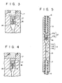
- Float 14 then abuts against the upper wall (i.e., closure member 16) at this velocity. With this impact, float 14 tightly adheres to closure member 16 and will not be allowed to fall even after the flow rate recovers to the normal value ( F ig. 3). In this state, the flow rate of therapeutic fluid cannot be measured.
- valve 17 is included according to the present invention, it is also moved upward upon flow of excess fluid as shown in Fig. 3. However, when the flow rate recovers to the normal value, valve 17 falls by its own weight. Then, rod 17b contacts float 14 to strike it down to its original position, thereby allowing flow rate measurement (Fig. 4).
Abstract
Description
- The present invention relates to a flowmeter and, more particularly, to a flowmeter to be assembled in a fluid therapy line for continuously injecting a therapeutic fluid into the body of a patient at a very low rate in order to prevent formation of a thrombus in a catheter when the catheter is indwelled in the patient's body over a relatively long period of time in an invasive blood pressure monitoring system or the like.
- Conventionally, a fluid therapy line has an intravenous drip chamber for measuring the flow rate of a therapeutic fluid injected into a patient's body. Such an intravenous drip chamber is also used in an invasive blood pressure monitorinq system. However, flow rate measurement with an intravenous drip chamber requires a relatively long period of time and may cause introduction of air into the patient's body during flushing or the like.
- As a fluid therapy flowmeter free from this problem, a flowmeter using a float is described in U.S. Patent No. 3,034,504 or Japanese Patent Publication No. 50-31466. However, when this type of flowmeter is assembled in an invasive blood pressure monitoring system connected to a flushing device, the float is caused to abut against the wall of the fluid outlet port by the excess fluid flowing during flushing. Even after the flow rate recovers to the normal value, the float remains attached to the wall and does not return to the original position. Then, a prescribed micro flow rate cannot be obtained, resulting in an unsatisfactory result.
- It is, therefore, an object of the present invention to provide a flowmeter wherein even if the float abuts against and becomes attached to the wall of the fluid outlet port due to flow of excess fluid flowing during flushing, the float can be allowed to fall to the original position and the flow rate can be recovered to the original value.
- According to the present invention, there is provided a flowmeter comprising:
- a main body having fluid inlet and outlet passages; and
- a vertical fluid channel formed in the main body and having one end communicating with the inlet passage and the other end communicating with the outlet passage,
- the vertical fluid channel having a first passage and a second passage having a cross-sectional area larger than that of the first passage,
- the first passage having therein a float for regulating a flow rate of the fluid flowing therethrough,
- the first passage being tapered to have a cross-sectional area thereof increasing from the inlet passage side toward the outlet passage side such that the float remains in position when the fluid passes through the first passage,
- the second passage having therein valve means for opening the second passage when the fluid is to flow therethrough and for closing the second passage when the fluid is not to flow therethrough,
- the valve means having a projection for moving the float toward the inlet passage when the second passage is closed, and
- the float and the valve means having specific gravities larger than that of the fluid when the first passage is arranged below the second passage, and having specific gravities smaller than that of the fluid when the first passage is arranged above the second passage.
- This invention can be more fully understood from the following detailed description when taken in conjunction with the accompanying drawings, in which:
- Fig. 1 is a perspective view showing a flowmeter according to the present invention when it is assembled in a fluid therapy line;
- Fig. 2 is a longitudinal sectional view showing a flowmeter according to a first embodiment of the present invention;
- Figs. 3 and 4 are sectional views for explaining the operation of the flowmeter according to the present invention;
- Fig. 5 is a longitudinal sectional view showing a second embodiment of the present invention; and
- Figs. 6 and 7 are longitudinal sectional views showing third and fourth embodiments of the present invention wherein tapered shapes are different.
- The present invention will be described in detail hereinafter.
- Fig. 1 shows a flowmeter according to the present invention, which is connected to a fluid therapy line. Fluid therapy bag 1 is compressed at a pressure of, e.g., 300 mmHg in pressure bag 2.
Flowmeter 5 of the present invention is connected to bag 1 throughcannula 3 and connectingtube 4. The outlet port offlowmeter 5 is connected to a flushing device (not shown) throughfluid therapy tube 6. Therapeutic fluid is injected into the patient's body through this line system and an indwelling catheter. - Fig. 2 shows the section of
flowmeter 5 according to the first embodiment of the present invention.Flowmeter 5 consists ofupper cap 7,main body 8, andlower cap 9. These three members are usually plastic molded members and is preferably formed of, e.g., a transparent resin such as polystyrene, polymethyl methacrylate, polycarbonate or the like. The three molded members are adhered by adhesion with a solvent, adhesion with an adhesive, or ultrasonic welding. -
Upper cap 7 hasfluid inlet passage 7a which receives connectingtube 4.Lower cap 9 has fluid outlet passage 9a which receivesfluid therapy tube 6. -
Vertical channel 11 is formed at the center ofmain body 8.Channel 11 has small-diameter portion lla, tapered portion llb, and large-diameter portion llc. Portion lla is tapered such that a lower 2/3 portion ofchannel 11 has an inner diameter slightly smaller than that of the remaining upper portion.Portions 11b and llc are continuous with portion lla. -
Float 14 for regulating the flow rate of the fluid is arranged in small-diameter portion lla ofvertical channel 11. Float 14 preferably has a spherical shape and has a specific gravity larger than that of the fluid.Float 14 is set such that the flow rate is defined by the difference in diameter offloat 14 and portion lla. Examples of the material forfloat 14 include glass, ruby, stainless steel, plastic, or carbon. These materials have different specific gravities. In order to allow the float to be stably positioned at a prescribed position at a predetermined flow rate, the diameter of portion lla must be selected in accordance with the specific gravity of the material selected forfloat 14. For example, if the therapeutic fluid is flowed at a very small, constant rate of 2 to 4 mℓ/hour as in a continuous micro rate fluid therapy line connected to a flushing device, carbon or plastic having a small specific gravity is preferable since it allows a larger diameter difference with respect to portion lla. In this case,spherical float 14 preferably has a diameter of 0.8 mm and small-diameter portion lla preferably has a diameter of 0.9 to 1.0 mm. If the therapeutic liquid flows at a normal rate of 2 to 4 mℓ/hour, the scale is set at a predetermined position on the outer surface of portion lla, as shown in Fig. 1. When the flow rate is, e.g., 3 mi/hour, the tapered diameter of portion lla is set such that the float stops at a position corresponding to the scale value of 3 mt/hour. - Large-diameter portion llc of
vertical channel 11 has a diameter three times or more of that of small-diameter portion lla. Closuremember 16 crosses portion llc and hasnarrow communication portion 15 at its central portion. Valve 17 is arranged inclosure member 16. Valve 17 consists of head 17a arranged onclosure member 16 androd 17b connected to head 17a.Rod 17b is inserted incommunication portion 15 ofclosure member 16 with a gap. Valve 17 preferably has a large specific gravity and high corrosion resistance and preferably consists of stainless steel. As will be described later, due to the flow of excess therapeutic fluid during flushing,valve 17 abuts against the inner wall ofupper cap 7. In this case, however,rod 17b is preferably located at least insidecommunication portion 15. In particular, the lower portion ofvalve 17 is preferably located at the same level or lower than the upper half ofclosure member 16. The gap betweencommunication portion 15 androd 17b inserted therein must be smaller than the diameter offloat 14 so as not to allowfloat 14 to pass therethrough. - First and
second side channels main body 8.First side channel 12 allows the fluid to flow frominlet passage 7a to the bottom ofchannel 11.Second side channel 13 allows the fluid to flow from the top ofvertical channel 11 to outlet passage 9a. In order to allowfloat 14 to stay inchannel 11, the level ofcross passage 18 connectingchannels float 14. - Fig. 5 shows a longitudinal sectional view of a flowmeter according to a second embodiment of the present invention. In the flowmeter shown in Fig. 5, the inlet and outlet passages are simplified. More specifically, the inlet passage defined by
tube 4 is connected to the bottom ofchannel 11, and the outlet passage defined bytube 6 is connected to the top ofchannel 11. This flowmeter operates in the same manner as that of the first embodiment. - Figs. 6 and 7 show flowmeters according to the third and fourth embodiments of the present invention. Fig. 6 shows a longitudinal sectional view of a flowmeter having the same configuration as that shown in Fig. 2 except that tapered portion llb is omitted. Fig. 7 shows a longitudinal sectional view of a flowmeter having the same configuration as that shown in Fig. 5 except that tapered portion llb is omitted. The flowmeters shown in Figs. 6 and 7 operate in the same manner as that of the first embodiment.
- When a therapeutic fluid is flowed at a normal rate of 2 to 4 mt/hour,
valve 17 is located at the position shown in Fig. 2. The fluid flowing in throughinlet passage 7a flows down inchannel 12 and reachesvertical channel 11. The fluid then flows upchannel 11 and flows out through outlet passage 9a viachannel 13. Since the therapeutic fluid is compressed at a predetermined pressure as described above,valve 17 slightly floats to assure the small rate flow passage of the fluid. If required, the upper surface ofclosure member 16 can be slightly inclined. In this case, the flow passage is more easily obtained. - During priming or flushing for blood cleaning in a fluid therapy line including a flowmeter as described above, the therapeutic fluid flows at a flow rate of 2,400 to 7,200 m1/hour. This flow rate is 1,000 times or more that in constant, micro rate fluid therapy. When the flow rate during flushing is set at 3,000 mℓ/hour and the diameter of portion lla of
vertical channel 11 is set at 1 mm, the linear velocity of the fluid in portion lla is about 100 cm/sec.Float 14 then abuts against the upper wall (i.e., closure member 16) at this velocity. With this impact, float 14 tightly adheres toclosure member 16 and will not be allowed to fall even after the flow rate recovers to the normal value (Fig. 3). In this state, the flow rate of therapeutic fluid cannot be measured. - If
valve 17 is included according to the present invention, it is also moved upward upon flow of excess fluid as shown in Fig. 3. However, when the flow rate recovers to the normal value,valve 17 falls by its own weight. Then,rod 17b contacts float 14 to strike it down to its original position, thereby allowing flow rate measurement (Fig. 4). - In summary, according to the present invention, even if flushing is performed with an excessive amount of a therapeutic fluid, when the flow rate recovers to the normal value, the float is allowed to fall to its original position by
valve 17. Normal flow rate measurement can then be initiated immediately.
Claims (7)
Applications Claiming Priority (2)
| Application Number | Priority Date | Filing Date | Title |
|---|---|---|---|
| JP60244364A JPS62103520A (en) | 1985-10-31 | 1985-10-31 | Flowmeter |
| JP244364/85 | 1985-10-31 |
Publications (2)
| Publication Number | Publication Date |
|---|---|
| EP0221501A1 true EP0221501A1 (en) | 1987-05-13 |
| EP0221501B1 EP0221501B1 (en) | 1991-08-07 |
Family
ID=17117592
Family Applications (1)
| Application Number | Title | Priority Date | Filing Date |
|---|---|---|---|
| EP86114983A Expired EP0221501B1 (en) | 1985-10-31 | 1986-10-28 | Flowmeter |
Country Status (4)
| Country | Link |
|---|---|
| US (1) | US4699617A (en) |
| EP (1) | EP0221501B1 (en) |
| JP (1) | JPS62103520A (en) |
| DE (1) | DE3680745D1 (en) |
Cited By (1)
| Publication number | Priority date | Publication date | Assignee | Title |
|---|---|---|---|---|
| CN101294826B (en) * | 2008-06-10 | 2012-11-28 | 张亚根 | Intelligent liquid phase air bubble flow measuring and observing device |
Families Citing this family (15)
| Publication number | Priority date | Publication date | Assignee | Title |
|---|---|---|---|---|
| US5205834A (en) * | 1990-09-04 | 1993-04-27 | Moorehead H Robert | Two-way outdwelling slit valving of medical liquid flow through a cannula and methods |
| US5169393A (en) * | 1990-09-04 | 1992-12-08 | Robert Moorehead | Two-way outdwelling slit valving of medical liquid flow through a cannula and methods |
| US5201722A (en) * | 1990-09-04 | 1993-04-13 | Moorehead Robert H | Two-way outdwelling slit valving of medical liquid flow through a cannula and methods |
| JPH0568548U (en) * | 1992-02-06 | 1993-09-17 | 東京計装株式会社 | Drip solution control device |
| US5526695A (en) * | 1994-08-19 | 1996-06-18 | Sundstrand Corporation | Pulsed flow meter |
| US5651775A (en) | 1995-07-12 | 1997-07-29 | Walker; Richard Bradley | Medication delivery and monitoring system and methods |
| US5717137A (en) * | 1996-02-01 | 1998-02-10 | Standex International Corporation | Flow monitoring line strainer |
| DE29905655U1 (en) * | 1999-03-26 | 1999-08-05 | Reich Kg Regel & Sicherheits | Measuring device for measuring the flow rate and temperature of a flowable medium |
| JP4510441B2 (en) * | 2001-05-25 | 2010-07-21 | インテグリス・インコーポレーテッド | Fluoropolymer flow meter |
| BE1014493A6 (en) * | 2001-11-23 | 2003-11-04 | Beria Soci T Anonyme | Improved infusion line float and flow meter for a line infusion. |
| US6935190B1 (en) * | 2002-04-23 | 2005-08-30 | Massachusetts Institute Of Technology | Flow rate measurement apparatus |
| DE10253086B4 (en) * | 2002-11-13 | 2005-02-03 | Krohne Meßtechnik GmbH & Co KG | Schwebekörperdurchflußmeßgerät |
| JP2010099454A (en) * | 2008-09-25 | 2010-05-06 | Nippon Sherwood Medical Industries Ltd | Liquid flow detector, transfusion line provided with same, and liquid flow detection method |
| US8132470B2 (en) * | 2009-04-21 | 2012-03-13 | Tyco Healthcare Group Lp | Fluid flow detector having a mobile body moving between a detection channel and a discharge channel |
| US9237986B2 (en) * | 2013-03-14 | 2016-01-19 | Carefusion 303, Inc. | Vial access cap and syringe with gravity-assisted valve |
Citations (2)
| Publication number | Priority date | Publication date | Assignee | Title |
|---|---|---|---|---|
| US3034504A (en) * | 1958-11-21 | 1962-05-15 | Galasyn Inc | Flow meter for an intravenous injection unit |
| DE1923589A1 (en) * | 1968-05-22 | 1969-11-27 | Koehn Wilbur Raymond | Feeder for infusion fluids |
Family Cites Families (4)
| Publication number | Priority date | Publication date | Assignee | Title |
|---|---|---|---|---|
| US2778223A (en) * | 1953-11-02 | 1957-01-22 | Puritan Compressed Gas Corp | Flowmeter |
| US3049918A (en) * | 1960-03-11 | 1962-08-21 | Theodore Gregory | Fluid flowmeters |
| US3587313A (en) * | 1969-01-30 | 1971-06-28 | I V Ometer Inc | Flow meter for parenteral solutions |
| JPS5031466A (en) * | 1973-07-20 | 1975-03-27 |
-
1985
- 1985-10-31 JP JP60244364A patent/JPS62103520A/en active Granted
-
1986
- 1986-10-28 DE DE8686114983T patent/DE3680745D1/en not_active Expired - Fee Related
- 1986-10-28 EP EP86114983A patent/EP0221501B1/en not_active Expired
- 1986-10-31 US US06/925,254 patent/US4699617A/en not_active Expired - Lifetime
Patent Citations (2)
| Publication number | Priority date | Publication date | Assignee | Title |
|---|---|---|---|---|
| US3034504A (en) * | 1958-11-21 | 1962-05-15 | Galasyn Inc | Flow meter for an intravenous injection unit |
| DE1923589A1 (en) * | 1968-05-22 | 1969-11-27 | Koehn Wilbur Raymond | Feeder for infusion fluids |
Cited By (1)
| Publication number | Priority date | Publication date | Assignee | Title |
|---|---|---|---|---|
| CN101294826B (en) * | 2008-06-10 | 2012-11-28 | 张亚根 | Intelligent liquid phase air bubble flow measuring and observing device |
Also Published As
| Publication number | Publication date |
|---|---|
| US4699617A (en) | 1987-10-13 |
| DE3680745D1 (en) | 1991-09-12 |
| EP0221501B1 (en) | 1991-08-07 |
| JPS62103520A (en) | 1987-05-14 |
| JPH0321851B2 (en) | 1991-03-25 |
Similar Documents
| Publication | Publication Date | Title |
|---|---|---|
| US4699617A (en) | Flowmeter | |
| US5730730A (en) | Liquid flow rate control device | |
| US4136692A (en) | Flow meter administration device | |
| JPS60116369A (en) | Continuous flash apparatus and method | |
| US4269222A (en) | Constant flow device | |
| EP0614381A1 (en) | Fast flush catheter valve | |
| JPS59111765A (en) | Injection pump apparatus | |
| IE47065B1 (en) | Parenteral liquid administration device | |
| Dawes et al. | The density flowmeter, a direct method for the measurement of the rate of blood flow | |
| US3340871A (en) | Parenteral liquid administration apparatus | |
| US5722961A (en) | Flow control device for use with an intravenous set | |
| US3521635A (en) | Flowmeter de-aerator for parenteral fluid administration set | |
| US3204633A (en) | Volumetric automatic shut-off fluid valve for infusion apparatus | |
| US5483830A (en) | Method and apparatus for measuring a liquid flow using a siphon unit and an aerating duct | |
| US5599303A (en) | IV administration apparatus | |
| CA1328748C (en) | Tubular body, method of making tubular body, and flow control device having tubular body | |
| JP7325134B2 (en) | Flow metering inserts and/or devices | |
| JPH0337076A (en) | Liquid passing valve and medical apparatus using it | |
| US4906348A (en) | Flow-through cell provided with reference electrode | |
| GB2054802A (en) | Flow control apparatus | |
| US4459859A (en) | Flowmeter | |
| EP3294379B1 (en) | Flow meter for intravenous liquids | |
| US5432992A (en) | Method of making count probe with removable count wafer | |
| RU2176526C1 (en) | Device for metered drip infusion | |
| US4157043A (en) | Maximum pressure manometer |
Legal Events
| Date | Code | Title | Description |
|---|---|---|---|
| PUAI | Public reference made under article 153(3) epc to a published international application that has entered the european phase |
Free format text: ORIGINAL CODE: 0009012 |
|
| 17P | Request for examination filed |
Effective date: 19861125 |
|
| AK | Designated contracting states |
Kind code of ref document: A1 Designated state(s): BE DE FR GB NL SE |
|
| 17Q | First examination report despatched |
Effective date: 19890404 |
|
| GRAA | (expected) grant |
Free format text: ORIGINAL CODE: 0009210 |
|
| AK | Designated contracting states |
Kind code of ref document: B1 Designated state(s): BE DE FR GB NL SE |
|
| REF | Corresponds to: |
Ref document number: 3680745 Country of ref document: DE Date of ref document: 19910912 |
|
| ET | Fr: translation filed | ||
| PLBE | No opposition filed within time limit |
Free format text: ORIGINAL CODE: 0009261 |
|
| STAA | Information on the status of an ep patent application or granted ep patent |
Free format text: STATUS: NO OPPOSITION FILED WITHIN TIME LIMIT |
|
| 26N | No opposition filed | ||
| EAL | Se: european patent in force in sweden |
Ref document number: 86114983.9 |
|
| PGFP | Annual fee paid to national office [announced via postgrant information from national office to epo] |
Ref country code: FR Payment date: 19971009 Year of fee payment: 12 |
|
| PGFP | Annual fee paid to national office [announced via postgrant information from national office to epo] |
Ref country code: SE Payment date: 19971015 Year of fee payment: 12 |
|
| PGFP | Annual fee paid to national office [announced via postgrant information from national office to epo] |
Ref country code: GB Payment date: 19971020 Year of fee payment: 12 |
|
| PGFP | Annual fee paid to national office [announced via postgrant information from national office to epo] |
Ref country code: NL Payment date: 19971029 Year of fee payment: 12 |
|
| PGFP | Annual fee paid to national office [announced via postgrant information from national office to epo] |
Ref country code: DE Payment date: 19971031 Year of fee payment: 12 |
|
| PGFP | Annual fee paid to national office [announced via postgrant information from national office to epo] |
Ref country code: BE Payment date: 19971211 Year of fee payment: 12 |
|
| PG25 | Lapsed in a contracting state [announced via postgrant information from national office to epo] |
Ref country code: GB Free format text: LAPSE BECAUSE OF NON-PAYMENT OF DUE FEES Effective date: 19981028 |
|
| PG25 | Lapsed in a contracting state [announced via postgrant information from national office to epo] |
Ref country code: SE Free format text: LAPSE BECAUSE OF NON-PAYMENT OF DUE FEES Effective date: 19981029 |
|
| PG25 | Lapsed in a contracting state [announced via postgrant information from national office to epo] |
Ref country code: BE Free format text: LAPSE BECAUSE OF NON-PAYMENT OF DUE FEES Effective date: 19981031 |
|
| BERE | Be: lapsed |
Owner name: TERUMO K.K. TRADING AS TERUMO CORP. Effective date: 19981031 |
|
| PG25 | Lapsed in a contracting state [announced via postgrant information from national office to epo] |
Ref country code: NL Free format text: LAPSE BECAUSE OF NON-PAYMENT OF DUE FEES Effective date: 19990501 |
|
| GBPC | Gb: european patent ceased through non-payment of renewal fee |
Effective date: 19981028 |
|
| EUG | Se: european patent has lapsed |
Ref document number: 86114983.9 |
|
| PG25 | Lapsed in a contracting state [announced via postgrant information from national office to epo] |
Ref country code: FR Free format text: LAPSE BECAUSE OF NON-PAYMENT OF DUE FEES Effective date: 19990630 |
|
| NLV4 | Nl: lapsed or anulled due to non-payment of the annual fee |
Effective date: 19990501 |
|
| REG | Reference to a national code |
Ref country code: FR Ref legal event code: ST |
|
| PG25 | Lapsed in a contracting state [announced via postgrant information from national office to epo] |
Ref country code: DE Free format text: LAPSE BECAUSE OF NON-PAYMENT OF DUE FEES Effective date: 19990803 |