EP0221945B1 - Patient support appliances - Google Patents
Patient support appliances Download PDFInfo
- Publication number
- EP0221945B1 EP0221945B1 EP86902879A EP86902879A EP0221945B1 EP 0221945 B1 EP0221945 B1 EP 0221945B1 EP 86902879 A EP86902879 A EP 86902879A EP 86902879 A EP86902879 A EP 86902879A EP 0221945 B1 EP0221945 B1 EP 0221945B1
- Authority
- EP
- European Patent Office
- Prior art keywords
- air
- sacs
- base
- blower
- appliance according
- Prior art date
- Legal status (The legal status is an assumption and is not a legal conclusion. Google has not performed a legal analysis and makes no representation as to the accuracy of the status listed.)
- Expired - Lifetime
Links
Images


Classifications
-
- A—HUMAN NECESSITIES
- A61—MEDICAL OR VETERINARY SCIENCE; HYGIENE
- A61G—TRANSPORT, PERSONAL CONVEYANCES, OR ACCOMMODATION SPECIALLY ADAPTED FOR PATIENTS OR DISABLED PERSONS; OPERATING TABLES OR CHAIRS; CHAIRS FOR DENTISTRY; FUNERAL DEVICES
- A61G7/00—Beds specially adapted for nursing; Devices for lifting patients or disabled persons
- A61G7/05—Parts, details or accessories of beds
- A61G7/057—Arrangements for preventing bed-sores or for supporting patients with burns, e.g. mattresses specially adapted therefor
- A61G7/05769—Arrangements for preventing bed-sores or for supporting patients with burns, e.g. mattresses specially adapted therefor with inflatable chambers
- A61G7/05776—Arrangements for preventing bed-sores or for supporting patients with burns, e.g. mattresses specially adapted therefor with inflatable chambers with at least two groups of alternately inflated chambers
-
- A—HUMAN NECESSITIES
- A61—MEDICAL OR VETERINARY SCIENCE; HYGIENE
- A61G—TRANSPORT, PERSONAL CONVEYANCES, OR ACCOMMODATION SPECIALLY ADAPTED FOR PATIENTS OR DISABLED PERSONS; OPERATING TABLES OR CHAIRS; CHAIRS FOR DENTISTRY; FUNERAL DEVICES
- A61G2203/00—General characteristics of devices
- A61G2203/30—General characteristics of devices characterised by sensor means
- A61G2203/46—General characteristics of devices characterised by sensor means for temperature
-
- A—HUMAN NECESSITIES
- A61—MEDICAL OR VETERINARY SCIENCE; HYGIENE
- A61G—TRANSPORT, PERSONAL CONVEYANCES, OR ACCOMMODATION SPECIALLY ADAPTED FOR PATIENTS OR DISABLED PERSONS; OPERATING TABLES OR CHAIRS; CHAIRS FOR DENTISTRY; FUNERAL DEVICES
- A61G7/00—Beds specially adapted for nursing; Devices for lifting patients or disabled persons
- A61G7/002—Beds specially adapted for nursing; Devices for lifting patients or disabled persons having adjustable mattress frame
- A61G7/015—Beds specially adapted for nursing; Devices for lifting patients or disabled persons having adjustable mattress frame divided into different adjustable sections, e.g. for Gatch position
Definitions
- This invention relates to support appliances of the kind in which a patient is supported on a plurality of contiguous inflated air sacs.
- air is supplied to the sacs on the bed via individual conduits from a blower unit remote from the bed, the blower unit including pressure regulating valves so that the pressure of air supplied to different sections of the bed is controlled at the remote blower unit.
- the blower unit including pressure regulating valves so that the pressure of air supplied to different sections of the bed is controlled at the remote blower unit. While this arrangement has some technical and clinical advantages, e.g. it is easier to maintain high safety standards and reduce blower noise perceived by the user of the bed, the use or a separately housed blower, heater and control equipment and the need to connect the bed and blower unit with trailing hoses can be a disadvantage where space is limited.
- EP-A-0122666 describes a patient support appliance which comprises a plurality of inflatable cushions which are shaded to nest within a trough formed from blocks of foam rubber.
- the cushions are gas-tight and are inflated by pressurised air fed from a common duct. Pressure of air in each cushion or group of cushions is maintained at a preset pressure by an individual control valve.
- a patient support appliance comprising a base having a plurality of inflatable air sacs mounted on the base and extending transversely thereof so as to provide, when inflated, a surface for supporting a person thereon, characterised by said base providing a substantially flat-base and being divided into sections lengthwise of the appliance, some of said sections being mutually articulated, and said air sacs being arranged in groups corresponding to said sections, an air blower for supplying air to said sacs which blower is mounted beneath said base, a main air supply conduit for feeding air from the blower to a distribution chamber and individual air supply tubes each leading from the distribution chamber to one of said groups of sacs and for maintaining a flow of air through said sacs, individual pressure regulating valves to regulate individually the pressure of air in said air supply tubes so that the pressure in each group of sacs can be regulated independently of the others, means for switching said valves between a first configuration in which they are simultaneously in their substantially fully open position and a second configuration in which they are independently controllable to
- the blower unit is housed within the physical confines of the bed or its supporting frame, i.e. beneath the base and attached to the base or on a supporting frame.
- the blower is conveniently mounted on the trolley frame, while the distribution chamber and control valves may be mounted on the underside of the attitude frame.
- the distribution housing and control unit may be mounted at the foot end of the bed, in a position where manual controls for the pressures in individual bed sections are readily accessible.
- the distribution housing is conveniently connected to the blower output by a large diameter main flexible supply conduit.
- a large diameter main flexible supply conduit e.g.
- a pair of blowers may be mounted on the trolley frame (preferably in a common housing) and the outputs from these blowers fed to the distribution chamber via separate large diameter conduits.
- the blowers may feed a pair of supply conduits or a single supply conduit via a suitable manifold.
- non-return valves are desirably interposed in the supply conduits to prevent feed back of air from one blower to the other.
- an auxiliary air pump may be provided to supply air to the bellows. Since the bellows, in contrast to the air sacs, do not require a large continuous air flow, a small capacity air pump can be used which supplies a relatively small volume of air.
- the blower may also be suspended from the underside of the base or attitude frame, preferably as close as possible to the axis about which the attitude frame pivots on the trolley frame.
- the location of the blower will depend upon the type of support structure used to provide a support for the appliance.
- Most standard hospital beds will include a frame work on which the blower unit can be mounted. In some environments, it may be satisfactory to place the blower within the overall confines of the support structure without actually fixing it to the support structure.
- the blower may be suspended from the base of the support appliance provided that it does not prevent the appliance being fitted to the desired hospital bed or other support structure.
- the distribution chamber in support appliances of the kind described in our U.K. Patent Specification No.2,141,333 takes the form of a tubular member extending lengthwise of the appliance.
- the distribution chamber may also be in a tubular form in the integral type of bed as described e.g. in U.K. Patent No.1,474,018.
- the tubular chamber may be fed with air at blower output pressure via a main supply conduit which is connected to the tubular chamber at one end of the appliance or via a connector in the region of the seat section.
- the distribution chamber comprises a tube of rectangular, oval or flattened oval cross section, extending beneath the flat, obstruction free base surface of the appliance sections.
- the tubular chamber consists of a number of tubular portions which are joined by flexible connectors in the areas of the hinges. Air is supplied to individual groups of sacs by individual hoses which are connected to the tubular distribution chamber at appropriate intervals along the appliance, normally one hose for each group of sacs.
- a patient support appliance which comprises a plurality of contiguous elongated inflatable air sacs extending transversely of the appliance so as to provide a patient support surface, said air sacs being mounted on at least three mutually articulated sections, each corresponding approximately to the upper part of the body, the seat and the legs of the patient, said sacs being divided into a plurality of groups lengthwise of the bed, an individual supply conduit for each group of sacs, each of which is connected to a common main supply conduit leading from a source of pressurised air to said sections and pressure regulating means located in said sections for regulating the individual pressures supplied to the groups of sacs.
- the common supply conduit is connected to a tubular member or trunking which extends through the sections of the bed.
- the connection may be made through the seat section or through one of the end sections.
- branch connections may be made to feed the individual groups of sacs.
- a pressure regulating valve may be located at one end of the branch connection or conduit or at some point along its length.
- the branch conduits each feed a header chamber for supplying a respective group of sacs.
- the trunking or tubular members may be joined with one or more flexible connectors.
- appliances in which the air is fed through the sections to the groups of sacs at individually regulated pressures require the individual supply hoses to be removed and re-threaded through the sections when the appliance is disassembled or assembled.
- the space occupied by a blower and heater unit is substantially reduced by incorporating the heater within the blower. It has been found surprisingly that a heater can be readily incorporated within a centrifugal blower by attaching a heater element to the diaphragm of the blower or to one of the stator blades or alternatively to the periphery of the blower housing. By incorporating the blower and the heater within the same casing the total space occupied by the blower and heater can be substantially reduced.
- a centrifugal fan has the advantage that it is able to deliver large quantities of air at a relatively constant, though low, pressure. This provides an ideal type of air supply since the beds of the present invention do not require an air supply at a pressure significantly in excess of 40 millimetres of mercury but require an air flow of at least about 30 cubic feet per minute (0.85 cubic metres per minute) in order to sweep away the perspiration and other fluids which are carried into the air sacs and to convey heat to the bed.
- a patient supporting surface is formed by a plurality of air sacs 10 which are arranged to extend transversely across the bed.
- Air sacs 10 may be grouped in groups of 4 to 5 sacs labelled A to E, the air in each group of sacs being capable of being pressurised to different pressures so that the patient is subjected to minimum skin contact pressure over the overall area of his body.
- the pressure applied to the patient's skin should be less than that which would begin to close capillary veins so that pressure sores are avoided.
- housings 11, 12, 13, 14 and 15 which constitute a base. These housings are articulatedly connected together except for housings 11 and 12 which are rigidly joined. Housings 11 and 12 are intended for supporting the head and thorax of the patient while the housings 13, 14 and 15 serve for supporting the buttocks, thigh and lower legs and feet of the patient, respectively.
- the bed can be contoured to any desired shape by inflating or deflating the bellows 16 and 17 which will raise or lower housings 11 and 12 or 15 respectively by the action against a reaction board or support structure 18. Housing 13 (group C) is anchored to the board 18.
- Extendible linkages may be provided between the board 18 and the housings 15 and 11 and 12 to give lateral stability to the sections as they are raised.
- the beard 18 may be formed in separate sections which are hinged together for ease of packing and transport.
- Side frames 2 are pivotally connected at brackets 3 and 4 to housings 15 and 11 respectively. If the appliance is intended to be used on a standard hospital bed which has articulated sections, the bellows 16 and 17 and the board 18 may be dispensed with and the housings 11 to 15 fitted to the appropriate sections of the standard hospital bed. Obviously, it may be necessary to adjust the dimensions of the housings to correspond with those of the hospital bed.
- An air supply for feeding the air sacs 10 and the bellows 16 and 17 is conducted to the bed by a conduit 19 and distributed to the air sacs and to the bellows by a tubular member 20 (see Figure 3) extending the length of the bed and which serves as a distribution chamber.
- Air is supplied to the tubular member 20 from the large diameter flexible main conduit 19.
- Conduit 19 may be connected to a blower unit located beneath the board 18 or attached to the frame of some supporting structure such as a hospital bed frame.
- a supply of air may be provided from a self-standing blower housing or from a remote location and fed to the hospital room or ward via permanently installed trunking.
- Figure 1 shows the air being fed initially to the housing C from beneath the bed
- air may alternatively be supplied via a connector 21 to one end of the bed as shown in Figure 3.
- connector 21 is a quick-release connector, e.g. with a toggle latch, so that air can be released rapidly from the bed in an emergency or for ease of dismantling for transport.
- the tube 20 extends within the depth of the sections A to E lengthwise of the bed. It is therefore normally generally rectangular or of flattened oval cross-section and at least in the portions which bridge individual housings is preferably formed from a flexible plastic tube or tubes 20A reinforced with resilient plastic ribs.
- the tubular portions of member 20 need not extend the entire length of each section.
- the tubular portions are fabricated as elongated, rectangular boxes which are joined, via suitable fittings, at their ends to an adjacent rectangular box via one or more flexible tubes.
- the tube 20 also supplies air to the bellows at the foot and head of the bed.
- each housing may be closed off with a board or panel 34 to provide a space within each housing 35 in which is housed the air feed tube 20A and the other components of the bed to be described later.
- a projecting portion 36 of the top panel 32 is formed with a slot 37 extending across the width of the housing.
- Slot 37 is designed to accept one half of a plastic hinge (e.g. of polypropylene) and this hinge may be shaped, for example, as a double dovetail or dumbell.
- a plastic hinge e.g. of polypropylene
- this hinge may be shaped, for example, as a double dovetail or dumbell.
- the individual units are joined together by sliding the plastic hinge into corresponding slots 37 in adjacent units in such a way that the adjacent units are articulatedly connected together without any gap between the units through which dirt or fluids can pass.
- the bed can be supplied as a number of individual housings A to E, a hinged baseboard and a compact blower and heater unit.
- the binge between sections B and C may be of a different design from the hinges between other sections in order to allow for the sections to move apart (and thereby prevent the air sacs being squeezed) as the head section is raised.
- Each unit is formed with an air supply header chamber 38 and an exhaust chamber 39 and the sacs are connected across a pair of supply and exhaust header chambers by bayonet air sac connectors 40 (only one is shown) extending into the header chambers.
- bayonet air sac connectors 40 (only one is shown) extending into the header chambers.
- the construction of the connectors 40 and of the spigot portion on the air sacs which cooperates with them to give a quick-release connector is described in European published patent application No.0034954.
- Air is supplied to header chambers 38 by a branch tube 41 which is connected at one end to tube 20 and at the other via a valve 42 to header chamber 38.
- Air supply to header chamber 38 is controlled by an electric motor and gear box 43 arranged to drive each valve 42.
- a printed circuit board 44 carries a transducer and motor control components to determine both the pressure in the header chamber 38 and to convey instructions to the motor to adjust valve 42.
- a microprocessor 45 is located in the foot section E of the bed and incorporates a PROM whereby the individual pressures in the air sac units can be established and maintained within predetermined limits. These pressures can be altered by a hand operated programmer unit illustrated in Figure 12.
- Air is exhausted from the exhaust chamber 39 via a compensator valve 46 whose construction is described in our British Patent Specification No. 1,601,808.
- a flow rate between about 35 to 45 cubic feet per minute (1 to 1.27 cubic metres per minute) at a pressure of about 1/2 p.s.i. pressure (6.9 to 13.8 kilo pascals) is satisfactory.
- Raising or lowering the head or foot section of the bed is achieved by inflating the bellows 16 or 17 (shown in Figure 1) either by a solenoid actuated valve of the kind shown in Figure 4 of British Patent Application No. 2,077,859 or by an air operated valve 47 which is constructed in accordance with Figures 3 and 4 of our British Patent Application No. 2,070,426.
- the air sacs are connected to the air supply holes such as 40 in the panel forming the upper surface of the section A to E and the supply header chamber 38 and exhausted through similar holes in exhaust chamber 39, using connectors of the kind shown in Figures 5 to 8 of European Published Application No. 0,034,954, and this connector system enables the air sacs to be connected or disconnected very rapidly.
- the air sacs 10 are normally all of the same height, typically 25 to 30 centimetres high and 76 centimetres long, but it may be desirable to provide bags of different heights, e.g. up to 46 centimetres high and to arrange these bags transversely of the bed in order to give a contoured surface when the bed is in the flat position.
- shaped bags may be employed. For example, bags of general U-shaped form may be incorporated in the central or seat section so that bed pans or similar devices may be placed within the bed.
- the blower housing consists of the box 50 lined with sound proofing material in which is supported an electric motor 51 driving a centrifugal blower 52.
- the blower may consist of one or more stages and conveniently a heater 53 is attached to the end plate or diaphragm of the blower or to one or more of the stator diaphragms. It is convenient to attach the heater element to the end diaphagm as shown at 53 since this facilitates wiring of the heater element.
- the heater may consist of a mat of silicone rubber in which the heater elements are bonded. Air is drawn into the blower casing through a filter (not shown).
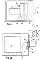
- Air is supplied by the blower from outlet tube 54 and the arrangement for connecting the blower to the supply conduit 19 to the bed is shown in Figure 4A.
- the blower end of conduit 19 is connected in airtight manner to a flange 55 (see Fig 4B) which is arranged to slide in a slot 56 formed in a projecting boss 57 attached to the outer wall of the blower housing.
- Air is fed to the conduit 19 via a tube 58 and an airtight seal is achieved by a flexible sleeve 59.
- the sleeve 59 which is lozenge-shaped in section and is formed from a flexible rubberised material, is inflated and its end face is pressed by air pressure onto the rear face of flange 55.
- FIGS. 7 to 11 show a bed whose construction is generally as described in our prior patent No.1,474,018, and like reference numerals used in Figure 7 refer to the same parts as indicated by the same reference numerals in our above prior patent.
- the superstructure of the bed is supported on an attitude frame 18 which is mounted on a trolley frame 12.
- the trolley frame 12 includes a pair of struts 16 on which the attitude frame 18 is pivotably connected at axis 19.
- Struts 22 and 22a are connected to the attitude frame 18 at their upper ends and to each other at their lower ends by a transverse bar 93.
- a motorised actuator shown diagrammatically at 21, acts between the transverse bar 93 and the trolley frame 12 to pivot the attitude frame 18 around the axis 19.
- a pump unit 92 Mounted beneath the attitude frame 18 is a pump unit 92 whose construction may be generally as described above. A centrifugal blower is preferred. Blower unit 92 is mounted beneath attitude frame 18 via anti-vibration rubber dampers (not shown). The blower may be as shown in Figures 4 and 4A with the axis of the motor and blower vertically inclined. The air output from blower unit 92 is conducted via a conduit 94 to a box 100 which is mounted beneath the attitude frame 18 and which constitutes a distribution chamber. The box 100 contains a heating element. Connected to the box 100 or integrally formed therewith is a housing 98 which contains heater controls and pressure gauges including a thermostat pressure measuring valve and devices for detecting any excess temperature developed within the bed. The housing 98 includes a front panel 99 on which temperature indicators, pressure indicator dials 99a, switches and other controls are mounted. A partial view of the control panel 99 is shown in Figure 9.
- FIG. 8 shows a schematic view of the air supply arrangement for the bed.
- Air produced by the air blower housed in blower cabinet 92 passes into a housing 95 and then via conduit 94 into heater box 100.
- Housing 95 also has an outlet conduit 95a for supplying air at blower pressure via electrically controlled valves (not shown) to head and foot bellows 28 and 31 respectively.
- Air supplied via conduit 94 to box 100 is heated to a thermostatically controlled temperature and passes via individually controlled pressure regulating valves to outlet conduits 101 to 105 (see Figure 9).
- Each of these outlet conduits 101 to 105 supplies air at individually regulated pressure to one of the five sections of the bed via header chambers mounted within sub-frames 23, 24, 25 and 26 of the bed.
- Mounted beneath the box 100 is an air dump valve 110 which consists of a plate slidably mounted in guides so that pulling the handle 111 in the direction of the arrow X exposes a large opening in the base of the chamber 100.
- This hole is normally covered by a flap valve manufactured from flexible material, so that in normal condition, the pressure within the chamber 100 seals the flap valve over the edges of the hole.
- the flap valve On removing the supporting plate by pulling handle 111, the flap valve is pushed outwardly and exposes the hole. The effect of this is to cause the air to exhaust from chamber 100 and the inflated air sacs 38 to deflate partly by air passing out through their inlet valves (to be described later) and partly though escape of air through the exhaust valves in the exhaust header chambers.
- the handle 111 would be operated in the case where the patient suffered cardiac arrest. In such a case, immediate emergency treatment would be to supply cardiac massage to the patient for which a hard flat surface is desirable. This is achieved rapidly by shutting off the blower motor and pulling the handle 111 to rapidly exhaust air from the sacs.
- the bed would therefore preferably include a proximity switch mounted beneath the chamber 100 so as to be actuated by contact with handle 11 when it is operated.
- a proximity switch mounted beneath the chamber 100 so as to be actuated by contact with handle 11 when it is operated.
- a signal would be transmitted to the control valves for the bellows, the effect of which would be to open the bellows exhaust valves and allow air to escape from the bellows.
- the clamp valve may be a plate which is attached to an arm so that it can be pivoted away from a corresponding hole in the base or wall of the distribution chamber. The plate may be spring-loaded into contact with the rim of the hole.
- the air sacs (or the upper surface thereof) is made from a microporous fabric which is non-permable to air but is permeable to water vapour.
- a microporous fabric which is non-permable to air but is permeable to water vapour.
- One such material is a microporous polyurethane-coated nylon manufactured by Carrington Performance Fabrics.
- Another is the polytetrafluoroethylene coated fabric available under the trade mark 'Gortex'.
- a position sensitive electrical switch such as a mercury switch
- thin switch would also be activated on pulling the emergency handle 111 to send a signal to the actuator 21 to cause the bed to be returned quickly from whatever attitude it was in at the time to the horizontal position.
- Suitable relays and interlocks would be provided to prevent these switches operating except in a desired sequence and in an emergency situation.
- a further refinement which is advantageous in the normal nursing of patients on beds in accordance with the invention is to provide a manually operated valve connected to the header chamber in the seat section of the bed.
- This may consist of a short plastic pipe with a manually operated valve extending therefrom.
- a simple vane valve may be suitable.
- the plastic pipe is a part of the air supply feed to the group of sacs in the seat section.
- the effect of closing the valve is to shut off the supply of air to the seat section, thereby allowing the sacs in this region to deflate or partially deflate by exhausting through the exhaust header chamber.
- a nurse may, by operating this valve, deflate the air sacs in this region for introducing a bed pan beneath the patient, or changing the sacs in this region.
- the sacs will reinflate to their previously predetermined pressure.
- FIGS 9 to 11 show the controls for the individual pressure regulating valves for each of the five groups of sacs on the bed shown in Figures 7 and 8.
- the feed of air from the blower supply via conduit 94 to each sac supply conduit 101 to 105 is controlled by individual valves 121 to 125.
- Each of these valves includes a rotatable valve stem 126 which when rotated provide by means of knob 127 in a clockwise direction will lift plate 128 off valve port 129 by an amount dependent on the degree by which it is turned. The amount by which each valve plate is raised from its valve seat will predetermine the pressure of air within the group of sacs which it feeds.
- the individual valves may also be opened by depressing valve stem 126 in the direction of the arrow Y against the effect of spring 130.
- the valve stems 126 can be depressed in the direction of arrow Y simultaneously by pressing on plate 131.
- This downward movement can be effected by rotating cam 132.
- the effect of this movement is to open all of the valves 121 to 125 to their maximum extent simultaneously and results in application of maximum air pressure (blower pressure) to all groups of sacs.
- maximum air pressure blowwer pressure
- the cam 132 can be returned to its non-operative position which allows the plate 131 to be lifted off the control knobs 127 and the valves will then return to their individual regulated preset pressure.
- FIG. 7 to 11 may be modified by dispensing with a distribution chamber and controls mounted on the supporting frame of the bed and instead providing equivalent functions in the bed sections 23, 24, 25 and 26.
- these sections of the bed may be constructed as shown in Figures 1 to 6 and the outlet conduit 94 from the blower 92 connected directly to a tubular member (similar to tube 20 in Figure 1) in the seat section 24.
- the electrical supply to the beds includes a mains supply to the motor and heater and a transformer to power the electrical services on the bed including temperature and pressure control.
- the electrical circuit also includes a sensor to sense the temperature of the air supply to the bed, the temperature within the bed and the blower motor temperature. These measurements are separately monitored and the supply automatically shut off in the event of excess temperature in any of these areas.
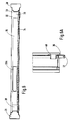
- Figure 12 shows the remote hand-operated programmer unit 81 for setting the pressures in the individual groups of sacs in beds constructed in accordance with the invention.
- the unit 81 is connected to the microprocessor 45.
- the unit has a series of buttons 82 to 86 for selecting the groups of sacs where pressure is to be changed, and two buttons 87 and 88 for raising or lowering the air pressure.
- a further control button 89 enables the pressure in all groups to be altered simultaneously.
- Digital gauges 90 give constant displays of the pressure in each group of sacs.
- the microprocessor unit is programmed to monitor the pressure in each group of air sacs (via transducers 44) and to maintain the pressure which has been set for each group.
Abstract
Description
- This invention relates to support appliances of the kind in which a patient is supported on a plurality of contiguous inflated air sacs.
- In British patent application No.2,141,333 A, there is described a bed of the above kind in which one feature of its construction is that the elongated inflatable air sacs are arranged on flat obstruction free sections which are hingedly joined together. The bed described in the above-mentioned co-pending patent application may be mounted upon a standard hospital bed or constructed as part of a purpose built integral low air loss bed unit of the kind described in British patent No.1,474,018. The present invention relates to low air loss appliances of both kinds, i.e. those having their own custom-built trolley frames as well as appliances which can be fitted to a standard hospital bed frame such as a 'Kings Fund' bed or beds such as those manufactured by Hill-Rom or Joerns.
- In the appliances specifically described in the above prior specification air is supplied to the sacs on the bed via individual conduits from a blower unit remote from the bed, the blower unit including pressure regulating valves so that the pressure of air supplied to different sections of the bed is controlled at the remote blower unit. While this arrangement has some technical and clinical advantages, e.g. it is easier to maintain high safety standards and reduce blower noise perceived by the user of the bed, the use or a separately housed blower, heater and control equipment and the need to connect the bed and blower unit with trailing hoses can be a disadvantage where space is limited.
- EP-A-0122666 describes a patient support appliance which comprises a plurality of inflatable cushions which are shaded to nest within a trough formed from blocks of foam rubber. The cushions are gas-tight and are inflated by pressurised air fed from a common duct. Pressure of air in each cushion or group of cushions is maintained at a preset pressure by an individual control valve.
- According to one aspect of the present invention there is provided a patient support appliance comprising a base having a plurality of inflatable air sacs mounted on the base and extending transversely thereof so as to provide, when inflated, a surface for supporting a person thereon, characterised by said base providing a substantially flat-base and being divided into sections lengthwise of the appliance, some of said sections being mutually articulated, and said air sacs being arranged in groups corresponding to said sections, an air blower for supplying air to said sacs which blower is mounted beneath said base, a main air supply conduit for feeding air from the blower to a distribution chamber and individual air supply tubes each leading from the distribution chamber to one of said groups of sacs and for maintaining a flow of air through said sacs, individual pressure regulating valves to regulate individually the pressure of air in said air supply tubes so that the pressure in each group of sacs can be regulated independently of the others, means for switching said valves between a first configuration in which they are simultaneously in their substantially fully open position and a second configuration in which they are independently controllable to different openings, and emergency exhaust means for exhausting air rapidly from the distribution chamber whereby the sacs may be quickly deflated and the patient lowered onto said base for emergency resuscitation.
- The blower unit is housed within the physical confines of the bed or its supporting frame, i.e. beneath the base and attached to the base or on a supporting frame. There are various possible locations for the blower. If the bed is of the integral type described in British Patent No. 1,476,018, the blower is conveniently mounted on the trolley frame, while the distribution chamber and control valves may be mounted on the underside of the attitude frame. For example, the distribution housing and control unit may be mounted at the foot end of the bed, in a position where manual controls for the pressures in individual bed sections are readily accessible. The distribution housing is conveniently connected to the blower output by a large diameter main flexible supply conduit. However, in certain circumstances, e.g. where the dimensions of the space available make it more convenient, a pair of blowers may be mounted on the trolley frame (preferably in a common housing) and the outputs from these blowers fed to the distribution chamber via separate large diameter conduits. In the case where a pair of blowers are employed, the blowers may feed a pair of supply conduits or a single supply conduit via a suitable manifold. However, non-return valves are desirably interposed in the supply conduits to prevent feed back of air from one blower to the other.
- If the bed employs air operated bellows for contouring the patient supporting surface, e.g. as in U.K. Patent No.1,474,018, an auxiliary air pump may be provided to supply air to the bellows. Since the bellows, in contrast to the air sacs, do not require a large continuous air flow, a small capacity air pump can be used which supplies a relatively small volume of air.
- Alternatively, the blower may also be suspended from the underside of the base or attitude frame, preferably as close as possible to the axis about which the attitude frame pivots on the trolley frame. With this arrangement, more space is made available beneath the bed and this facilitates use of ancillary equipment such as a patient lift for assisting placement of patients on the bed.
- In the use of support appliances of the kind described in U.K. Patent Specification No.2,141,333, the location of the blower will depend upon the type of support structure used to provide a support for the appliance. Most standard hospital beds will include a frame work on which the blower unit can be mounted. In some environments, it may be satisfactory to place the blower within the overall confines of the support structure without actually fixing it to the support structure. Alternatively, the blower may be suspended from the base of the support appliance provided that it does not prevent the appliance being fitted to the desired hospital bed or other support structure.
- Preferably, the distribution chamber in support appliances of the kind described in our U.K. Patent Specification No.2,141,333, takes the form of a tubular member extending lengthwise of the appliance. The distribution chamber may also be in a tubular form in the integral type of bed as described e.g. in U.K. Patent No.1,474,018.
- The tubular chamber may be fed with air at blower output pressure via a main supply conduit which is connected to the tubular chamber at one end of the appliance or via a connector in the region of the seat section. In one preferred form, the distribution chamber comprises a tube of rectangular, oval or flattened oval cross section, extending beneath the flat, obstruction free base surface of the appliance sections. Where the appliance sections are articulated, the tubular chamber consists of a number of tubular portions which are joined by flexible connectors in the areas of the hinges. Air is supplied to individual groups of sacs by individual hoses which are connected to the tubular distribution chamber at appropriate intervals along the appliance, normally one hose for each group of sacs.
- By feeding the air supply to the bed in a large diameter supply conduit to a point close to the groups of air sacs and supplying individual groups of sacs in the bed from individual branch conduits via pressure regulating valves located in the vicinity of the sacs there are reduced pressure losses between the blower unit and the groups of sacs. Also, this arrangement reduces the complexity and number of the supply hoses and enables the construction of the bed to be simplified.
- According to a further aspect of the invention there is provided a patient support appliance which comprises a plurality of contiguous elongated inflatable air sacs extending transversely of the appliance so as to provide a patient support surface, said air sacs being mounted on at least three mutually articulated sections, each corresponding approximately to the upper part of the body, the seat and the legs of the patient, said sacs being divided into a plurality of groups lengthwise of the bed, an individual supply conduit for each group of sacs, each of which is connected to a common main supply conduit leading from a source of pressurised air to said sections and pressure regulating means located in said sections for regulating the individual pressures supplied to the groups of sacs.
- In a preferred embodiment of this aspect of the invention the common supply conduit is connected to a tubular member or trunking which extends through the sections of the bed. The connection may be made through the seat section or through one of the end sections. From the tubular member or trunking, branch connections may be made to feed the individual groups of sacs. A pressure regulating valve may be located at one end of the branch connection or conduit or at some point along its length. Preferably, the branch conduits each feed a header chamber for supplying a respective group of sacs. In the vicinity of hinges, the trunking or tubular members may be joined with one or more flexible connectors. One advantage of this type of air supply system is that when assembling or disassembling the sections, e.g. for transport, it is comparatively easy to connect the tubular members or trunking (which is retained within the sections) by connecting and disconnecting the flexible connectors at the hinges. In contrast, appliances in which the air is fed through the sections to the groups of sacs at individually regulated pressures (e.g. in U.K. Patent Specification No. 2,141,333) require the individual supply hoses to be removed and re-threaded through the sections when the appliance is disassembled or assembled.
- In further development applicable to all embodiments of this invention, the space occupied by a blower and heater unit is substantially reduced by incorporating the heater within the blower. It has been found surprisingly that a heater can be readily incorporated within a centrifugal blower by attaching a heater element to the diaphragm of the blower or to one of the stator blades or alternatively to the periphery of the blower housing. By incorporating the blower and the heater within the same casing the total space occupied by the blower and heater can be substantially reduced.
- A centrifugal fan has the advantage that it is able to deliver large quantities of air at a relatively constant, though low, pressure. This provides an ideal type of air supply since the beds of the present invention do not require an air supply at a pressure significantly in excess of 40 millimetres of mercury but require an air flow of at least about 30 cubic feet per minute (0.85 cubic metres per minute) in order to sweep away the perspiration and other fluids which are carried into the air sacs and to convey heat to the bed.
- Further features and advantages of the present invention will become further apparent from the various embodiments of support appliances and parts thereof constructed in accordance with this invention and which are shown in the accompanying drawings in which:-
- Figure 1 is a side elevation of a support appliance in accordance with the invention;
- Figure 2 is an end elevation looking in the direction of the arrow A in Figure 1;
- Figure 3 is a plan view of a modified appliance in accordance with the invention with the air sacs and the top panels of the housings removed;
- Figure 4 is a side elevation of a blower unit partly broken away to show the interior;
- Figure 4A is a side elevation of the blower unit seen from the direction of arrow Y in Figure 4 showing the method of connecting the air supply conduit to the blower unit;
- Figure 4B is a part view of the air supply conduit of Figure 4A
- Figure 5 is a plan view of the foot section of the appliance shown in Figure 3 with the cover plate removed;
- Figure 6 is a view in the direction of the arrow X in Figure 5;
- Figure 6A is a scrap view taken on the lines A-A in Figure 5;
- Figure 7 is a diagrammatic side elevation of a bed similar to that described in our British Patent No.1,474,018;
- Figure 8 is a schematic view of the blower and control box assembly of the bed shown in Figure 7;
- Figure 9 is a view partially broken away of the control panel;
- Figure 10 is a view showing the operating mechanism of the valves within the control box;
- Figure 11 is a section taken along the line A-A in Figure 9;
- Figure 11A and 11B show modifications of the control mechanism of the valves shown in Figures 10 and 11;
- Figure 12 is a plan view of a hand-operated programmer unit for setting the pressures in the group of air sacs in support appliances in accordance with the invention.
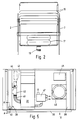
- Referring to Figures 1 to 6 of the accompanying drawings, the general principle of construction of the appliances shown in these embodiments is similar to that described in our above British published application No.2,141,333. As in our earlier application a patient supporting surface is formed by a plurality of
air sacs 10 which are arranged to extend transversely across the bed.Air sacs 10 may be grouped in groups of 4 to 5 sacs labelled A to E, the air in each group of sacs being capable of being pressurised to different pressures so that the patient is subjected to minimum skin contact pressure over the overall area of his body. The pressure applied to the patient's skin should be less than that which would begin to close capillary veins so that pressure sores are avoided. As can be seen in Figure 1 the groups of air sacs A to E are associated withhousings housings Housings housings bellows lower housings support structure 18. Housing 13 (group C) is anchored to theboard 18. Extendible linkages may be provided between theboard 18 and thehousings beard 18 may be formed in separate sections which are hinged together for ease of packing and transport. Side frames 2 are pivotally connected atbrackets housings bellows board 18 may be dispensed with and thehousings 11 to 15 fitted to the appropriate sections of the standard hospital bed. Obviously, it may be necessary to adjust the dimensions of the housings to correspond with those of the hospital bed. Also, some modification of the position and type of hinges will be necessary and this may involve dispensing with the existing hinges between the housings and between the sections on the bed. Where the appliance is fitted to a standard hospital bed which is already provided with actuators for contouring the sections A to E, the head and feet bellows may not be necessary. - An air supply for feeding the
air sacs 10 and thebellows conduit 19 and distributed to the air sacs and to the bellows by a tubular member 20 (see Figure 3) extending the length of the bed and which serves as a distribution chamber. Air is supplied to thetubular member 20 from the large diameter flexiblemain conduit 19.Conduit 19 may be connected to a blower unit located beneath theboard 18 or attached to the frame of some supporting structure such as a hospital bed frame. Alternatively, a supply of air may be provided from a self-standing blower housing or from a remote location and fed to the hospital room or ward via permanently installed trunking. Although Figure 1 shows the air being fed initially to the housing C from beneath the bed, air may alternatively be supplied via aconnector 21 to one end of the bed as shown in Figure 3. Preferablyconnector 21 is a quick-release connector, e.g. with a toggle latch, so that air can be released rapidly from the bed in an emergency or for ease of dismantling for transport. - The
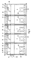
tube 20 extends within the depth of the sections A to E lengthwise of the bed. It is therefore normally generally rectangular or of flattened oval cross-section and at least in the portions which bridge individual housings is preferably formed from a flexible plastic tube ortubes 20A reinforced with resilient plastic ribs. The tubular portions ofmember 20 need not extend the entire length of each section. Preferably, the tubular portions are fabricated as elongated, rectangular boxes which are joined, via suitable fittings, at their ends to an adjacent rectangular box via one or more flexible tubes. In addition to feeding air to the air sacs via supply header chambers, thetube 20 also supplies air to the bellows at the foot and head of the bed. - The detailed construction of the individual housings is shown in Figures 5, 6 and 6A and it will be seen that these consist of a pair of extruded or rolled
longitudinal members panel 32 having a coveringskin 33 which provides a flat, obstruction-free surface on which to mount theair sacs 10. Figure 5 shows the foot section housing E but other sections are the same except that only sections A and E include bellows valves and only section E has a microprocessor board. The bottom of each housing may be closed off with a board orpanel 34 to provide a space within eachhousing 35 in which is housed theair feed tube 20A and the other components of the bed to be described later. A projectingportion 36 of thetop panel 32 is formed with aslot 37 extending across the width of the housing.Slot 37 is designed to accept one half of a plastic hinge (e.g. of polypropylene) and this hinge may be shaped, for example, as a double dovetail or dumbell. When assembling the bed the individual units are joined together by sliding the plastic hinge intocorresponding slots 37 in adjacent units in such a way that the adjacent units are articulatedly connected together without any gap between the units through which dirt or fluids can pass. It will be appreciated therefore that for packing and transport purposes the bed can be supplied as a number of individual housings A to E, a hinged baseboard and a compact blower and heater unit. The binge between sections B and C may be of a different design from the hinges between other sections in order to allow for the sections to move apart (and thereby prevent the air sacs being squeezed) as the head section is raised. - Each unit is formed with an air
supply header chamber 38 and anexhaust chamber 39 and the sacs are connected across a pair of supply and exhaust header chambers by bayonet air sac connectors 40 (only one is shown) extending into the header chambers. The construction of theconnectors 40 and of the spigot portion on the air sacs which cooperates with them to give a quick-release connector is described in European published patent application No.0034954. Air is supplied toheader chambers 38 by abranch tube 41 which is connected at one end totube 20 and at the other via avalve 42 toheader chamber 38. Air supply toheader chamber 38 is controlled by an electric motor andgear box 43 arranged to drive eachvalve 42. A printedcircuit board 44 carries a transducer and motor control components to determine both the pressure in theheader chamber 38 and to convey instructions to the motor to adjustvalve 42. Amicroprocessor 45 is located in the foot section E of the bed and incorporates a PROM whereby the individual pressures in the air sac units can be established and maintained within predetermined limits. These pressures can be altered by a hand operated programmer unit illustrated in Figure 12. - Air is exhausted from the
exhaust chamber 39 via acompensator valve 46 whose construction is described in our British Patent Specification No. 1,601,808. Generally, a flow rate between about 35 to 45 cubic feet per minute (1 to 1.27 cubic metres per minute) at a pressure of about 1/2 p.s.i. pressure (6.9 to 13.8 kilo pascals) is satisfactory. Raising or lowering the head or foot section of the bed is achieved by inflating thebellows 16 or 17 (shown in Figure 1) either by a solenoid actuated valve of the kind shown in Figure 4 of British Patent Application No. 2,077,859 or by an air operated valve 47 which is constructed in accordance with Figures 3 and 4 of our British Patent Application No. 2,070,426. - The air sacs are connected to the air supply holes such as 40 in the panel forming the upper surface of the section A to E and the
supply header chamber 38 and exhausted through similar holes inexhaust chamber 39, using connectors of the kind shown in Figures 5 to 8 of European Published Application No. 0,034,954, and this connector system enables the air sacs to be connected or disconnected very rapidly. Theair sacs 10 are normally all of the same height, typically 25 to 30 centimetres high and 76 centimetres long, but it may be desirable to provide bags of different heights, e.g. up to 46 centimetres high and to arrange these bags transversely of the bed in order to give a contoured surface when the bed is in the flat position. Also shaped bags may be employed. For example, bags of general U-shaped form may be incorporated in the central or seat section so that bed pans or similar devices may be placed within the bed. - The construction of the blower is shown in Figure 4. The blower housing consists of the
box 50 lined with sound proofing material in which is supported anelectric motor 51 driving acentrifugal blower 52. The blower may consist of one or more stages and conveniently aheater 53 is attached to the end plate or diaphragm of the blower or to one or more of the stator diaphragms. It is convenient to attach the heater element to the end diaphagm as shown at 53 since this facilitates wiring of the heater element. The heater may consist of a mat of silicone rubber in which the heater elements are bonded. Air is drawn into the blower casing through a filter (not shown). Air is supplied by the blower fromoutlet tube 54 and the arrangement for connecting the blower to thesupply conduit 19 to the bed is shown in Figure 4A. The blower end ofconduit 19 is connected in airtight manner to a flange 55 (see Fig 4B) which is arranged to slide in aslot 56 formed in a projectingboss 57 attached to the outer wall of the blower housing. Air is fed to theconduit 19 via atube 58 and an airtight seal is achieved by aflexible sleeve 59. When air passes throughtube 58 thesleeve 59 which is lozenge-shaped in section and is formed from a flexible rubberised material, is inflated and its end face is pressed by air pressure onto the rear face offlange 55. Because of the low pressure involved, this is sufficient to provide a satisfactory seal. Thus when it is desired to disconnect the bed rapidly from the source of air, e.g. in an emergency such as when the patient suffers cardiac arrest theflange 55 is simply slid out ofslot 56 and this immediately disconnects the air supply. - Referring now particularly to Figures 7 to 11, these figures show a bed whose construction is generally as described in our prior patent No.1,474,018, and like reference numerals used in Figure 7 refer to the same parts as indicated by the same reference numerals in our above prior patent. The superstructure of the bed is supported on an
attitude frame 18 which is mounted on atrolley frame 12. Conveniently, thetrolley frame 12 includes a pair ofstruts 16 on which theattitude frame 18 is pivotably connected ataxis 19.Struts attitude frame 18 at their upper ends and to each other at their lower ends by atransverse bar 93. A motorised actuator, shown diagrammatically at 21, acts between thetransverse bar 93 and thetrolley frame 12 to pivot theattitude frame 18 around theaxis 19. - Mounted beneath the
attitude frame 18 is apump unit 92 whose construction may be generally as described above. A centrifugal blower is preferred.Blower unit 92 is mounted beneathattitude frame 18 via anti-vibration rubber dampers (not shown). The blower may be as shown in Figures 4 and 4A with the axis of the motor and blower vertically inclined. The air output fromblower unit 92 is conducted via aconduit 94 to abox 100 which is mounted beneath theattitude frame 18 and which constitutes a distribution chamber. Thebox 100 contains a heating element. Connected to thebox 100 or integrally formed therewith is ahousing 98 which contains heater controls and pressure gauges including a thermostat pressure measuring valve and devices for detecting any excess temperature developed within the bed. Thehousing 98 includes afront panel 99 on which temperature indicators, pressure indicator dials 99a, switches and other controls are mounted. A partial view of thecontrol panel 99 is shown in Figure 9. - Referring to Figure 8, this shows a schematic view of the air supply arrangement for the bed. Air produced by the air blower housed in
blower cabinet 92 passes into ahousing 95 and then viaconduit 94 intoheater box 100.Housing 95 also has anoutlet conduit 95a for supplying air at blower pressure via electrically controlled valves (not shown) to head and foot bellows 28 and 31 respectively. - Air supplied via
conduit 94 tobox 100 is heated to a thermostatically controlled temperature and passes via individually controlled pressure regulating valves tooutlet conduits 101 to 105 (see Figure 9). Each of theseoutlet conduits 101 to 105 supplies air at individually regulated pressure to one of the five sections of the bed via header chambers mounted withinsub-frames box 100 is anair dump valve 110 which consists of a plate slidably mounted in guides so that pulling thehandle 111 in the direction of the arrow X exposes a large opening in the base of thechamber 100. This hole is normally covered by a flap valve manufactured from flexible material, so that in normal condition, the pressure within thechamber 100 seals the flap valve over the edges of the hole. On removing the supporting plate by pullinghandle 111, the flap valve is pushed outwardly and exposes the hole. The effect of this is to cause the air to exhaust fromchamber 100 and theinflated air sacs 38 to deflate partly by air passing out through their inlet valves (to be described later) and partly though escape of air through the exhaust valves in the exhaust header chambers. Thehandle 111 would be operated in the case where the patient suffered cardiac arrest. In such a case, immediate emergency treatment would be to supply cardiac massage to the patient for which a hard flat surface is desirable. This is achieved rapidly by shutting off the blower motor and pulling thehandle 111 to rapidly exhaust air from the sacs. - Air would not normally exhaust from the
bellows chamber 100 so as to be actuated by contact withhandle 11 when it is operated. Thus, on pulling the handle 111 a signal would be transmitted to the control valves for the bellows, the effect of which would be to open the bellows exhaust valves and allow air to escape from the bellows. As an alternative to a sliding plate, the clamp valve may be a plate which is attached to an arm so that it can be pivoted away from a corresponding hole in the base or wall of the distribution chamber. The plate may be spring-loaded into contact with the rim of the hole. - Preferably the air sacs (or the upper surface thereof) is made from a microporous fabric which is non-permable to air but is permeable to water vapour. One such material is a microporous polyurethane-coated nylon manufactured by Carrington Performance Fabrics. Another is the polytetrafluoroethylene coated fabric available under the trade mark 'Gortex'.
- It is also within the scope of the present invention to provide a position sensitive electrical switch (such as a mercury switch) which does detect when the
attitude frame 18 is not in its normal horizontal position. Preferably, thin switch would also be activated on pulling theemergency handle 111 to send a signal to theactuator 21 to cause the bed to be returned quickly from whatever attitude it was in at the time to the horizontal position. Suitable relays and interlocks would be provided to prevent these switches operating except in a desired sequence and in an emergency situation. - A further refinement which is advantageous in the normal nursing of patients on beds in accordance with the invention is to provide a manually operated valve connected to the header chamber in the seat section of the bed. This may consist of a short plastic pipe with a manually operated valve extending therefrom. A simple vane valve may be suitable. The plastic pipe is a part of the air supply feed to the group of sacs in the seat section. Thus, the effect of closing the valve is to shut off the supply of air to the seat section, thereby allowing the sacs in this region to deflate or partially deflate by exhausting through the exhaust header chamber. Thus, a nurse may, by operating this valve, deflate the air sacs in this region for introducing a bed pan beneath the patient, or changing the sacs in this region. On turning the manual valve to its closed position, the sacs will reinflate to their previously predetermined pressure.
- Referring to Figures 9 to 11, these show the controls for the individual pressure regulating valves for each of the five groups of sacs on the bed shown in Figures 7 and 8. The feed of air from the blower supply via
conduit 94 to eachsac supply conduit 101 to 105 is controlled byindividual valves 121 to 125. Each of these valves includes arotatable valve stem 126 which when rotated provide by means ofknob 127 in a clockwise direction will liftplate 128 offvalve port 129 by an amount dependent on the degree by which it is turned. The amount by which each valve plate is raised from its valve seat will predetermine the pressure of air within the group of sacs which it feeds. The individual valves may also be opened by depressing valve stem 126 in the direction of the arrow Y against the effect ofspring 130. The valve stems 126 can be depressed in the direction of arrow Y simultaneously by pressing onplate 131. This downward movement can be effected by rotatingcam 132. The effect of this movement is to open all of thevalves 121 to 125 to their maximum extent simultaneously and results in application of maximum air pressure (blower pressure) to all groups of sacs. The instantaneous inflation of all air sacs to maximum pressure enables, for example, a nurse to turn the patient more easily or to move the patient in the bed by sliding him on the firm surface of the sacs inflated at maximum pressure. After all the sacs have been inflated to maximum pressure (typically 25 to 30 mm of mercury) thecam 132 can be returned to its non-operative position which allows theplate 131 to be lifted off the control knobs 127 and the valves will then return to their individual regulated preset pressure. - It will be appreciated that instead of mounting the
cam 132 so that it presses on the tops of the operatingknobs 127, a neater arrangement can be provided by arranging theplate 131 so that it presses on thebushes 133 when the cam is operated. In this way, the valve stems 126 may project through the front panel of the control housing. Thecam 132 is then operated by pulling a rod (not shown) which extends through the panel of the control housing and is linked to arod 134 attached to the cam. The operation is shown in Figures 11A (valve closed position) and 11 (valve open position). - It will also be appreciated that the embodiment shown in Figures 7 to 11, may be modified by dispensing with a distribution chamber and controls mounted on the supporting frame of the bed and instead providing equivalent functions in the
bed sections outlet conduit 94 from theblower 92 connected directly to a tubular member (similar totube 20 in Figure 1) in theseat section 24. - The electrical supply to the beds includes a mains supply to the motor and heater and a transformer to power the electrical services on the bed including temperature and pressure control. The electrical circuit also includes a sensor to sense the temperature of the air supply to the bed, the temperature within the bed and the blower motor temperature. These measurements are separately monitored and the supply automatically shut off in the event of excess temperature in any of these areas.
- Figure 12 shows the remote hand-operated
programmer unit 81 for setting the pressures in the individual groups of sacs in beds constructed in accordance with the invention. Theunit 81 is connected to themicroprocessor 45. The unit has a series ofbuttons 82 to 86 for selecting the groups of sacs where pressure is to be changed, and twobuttons further control button 89 enables the pressure in all groups to be altered simultaneously. Digital gauges 90 give constant displays of the pressure in each group of sacs. The microprocessor unit is programmed to monitor the pressure in each group of air sacs (via transducers 44) and to maintain the pressure which has been set for each group.
Claims (15)
- A patient support appliance comprising a base having a plurality of inflatable air sacs (10) mounted on the base and extending transversely thereof so as to provide, when inflated, a surface for supporting a person thereon, characterised by said base providing a substantially flat surface and being divided into sections (11, 12, 13, 14 & 15) lengthwise of the appliance, some of said sections being mutually articulated, and said air sacs being arranged in groups corresponding to said sections, an air blower (52 or 92) for supplying air to said sacs which blower is mounted beneath said base, a main air supply conduit (19 or 94) for feeding air from the blower to a distribution chamber (20 or 100) and individual air supply tubes (41 or 101) each leading from the distribution chamber to one of said groups of sacs and for maintaining a flow of air through said sacs, individual pressure regulating valves (41 or 121 to 125) to regulate individually the pressure of air in said air supply tubes so that the pressure in each group of sacs can be regulated independently of the others, means for switching said valves between a first configuration in which they are simultaneously in their substantially fully open position and a second configuration in which they are independently controllable to different openings and emergency exhaust means (110) for exhausting air rapidly from the distribution chamber whereby the sacs may be quickly deflated and the patient lowered onto said base for emergency resuscitation.
- An appliance according to claim 1 wherein the distribution chamber comprises a housing mounted beneath said base or adjacent one end of the appliance.
- An appliance according to claim 1 or 2 wherein the means for exhausting air comprises an opening in said chamber which is normally covered by a plate, the plate being movable to expose the opening and exhaust air from the chamber.
- An appliance according to any one of the preceding claims wherein air flow through the sacs is controlled by an exhaust valve for each sac or group of sacs.
- An appliance according to claim 4 in which the exhaust valve is adapted to maintain an air flow, through the sac or group of sacs, which is greater than a predetermined minimum.
- An appliance according to any one of the preceding claims wherein the base is pivotably mounted on a trolley frame about a transverse axis which is located in the central region of the appliance and the distribution chamber and blower are both suspended from said base, the blower being located close to said transverse axis and the distribution chamber located in the region of one end of the bed.
- An appliance according to any one of the preceding claims wherein the pressure regulating valves are mounted side by side and each comprises a valve stem carrying a valve plate, which is movable towards and away from a valve seat to vary the flow of air through the valve.
- An appliance according to claim 7 which includes means for operating the valve stems of the regulating valves simultaneously.
- An appliance according to any one of the preceding claims wherein said emergency exhaust means is linked to means for controlling the articulation of the base, whereby on operating the emergency exhaust means, the base is brought to a horizontal condition.
- An appliance according to claim 1 wherein said main supply conduit comprises a tubular air supply member having a generally rectangular oval or flattened oval cross-section.
- An appliance according to claim 10 in which the tubular air supply member comprises a plurality of corresponding tubular portions, which are joined by flexible connection portions between adjacent articulated sections.
- An appliance according to any one of the preceding claims wherein each bed section comprises a pair of laterally spaced longitudinally extending members joined by a panel to form a flat, obstruction free surface, said longitudinal member being hollow and forming, respectively, supply and exhaust headers, for supplying air to and exhausting air from the sacs, the supply headers being connected via an individual air supply tube and a pressure regulating valve to said distribution chamber and the exhaust header being connected to exhaust valves for controlling the discharge of air to atmosphere.
- An appliance according to claim 12 in which each air sac is releasably attached to said base and connected to the supply and exhaust headers by releasable connectors.
- An appliance according to any one of the preceding claims wherein air pressure in each group of sacs is sensed by a transducer located in each bed section, the output from the transducers being monitored by a microprocessor which is programmable to set and maintain the pre-set pressure in each group of sacs.
- An appliance according to any one of the preceding claims wherein the air sacs, or their upper surfaces are made from a microporous fabric which is non-permeable to air but is permeable to water vapour.
Priority Applications (1)
| Application Number | Priority Date | Filing Date | Title |
|---|---|---|---|
| AT86902879T ATE81964T1 (en) | 1985-05-10 | 1986-05-09 | PATIENT SUPPORT DEVICE. |
Applications Claiming Priority (6)
| Application Number | Priority Date | Filing Date | Title |
|---|---|---|---|
| GB858511903A GB8511903D0 (en) | 1985-05-10 | 1985-05-10 | Patient support appliances |
| GB8511903 | 1985-05-10 | ||
| GB858517497A GB8517497D0 (en) | 1985-07-10 | 1985-07-10 | Air support appliance |
| GB8517497 | 1985-07-10 | ||
| GB8523577 | 1985-09-24 | ||
| GB858523577A GB8523577D0 (en) | 1985-09-24 | 1985-09-24 | Patient support appliances |
Publications (2)
| Publication Number | Publication Date |
|---|---|
| EP0221945A1 EP0221945A1 (en) | 1987-05-20 |
| EP0221945B1 true EP0221945B1 (en) | 1992-11-04 |
Family
ID=27262678
Family Applications (1)
| Application Number | Title | Priority Date | Filing Date |
|---|---|---|---|
| EP86902879A Expired - Lifetime EP0221945B1 (en) | 1985-05-10 | 1986-05-09 | Patient support appliances |
Country Status (7)
| Country | Link |
|---|---|
| US (1) | US4935968A (en) |
| EP (1) | EP0221945B1 (en) |
| JP (1) | JPH078288B2 (en) |
| AT (1) | ATE81964T1 (en) |
| DE (1) | DE3687060T2 (en) |
| GB (1) | GB8611529D0 (en) |
| WO (1) | WO1986006624A1 (en) |
Cited By (1)
| Publication number | Priority date | Publication date | Assignee | Title |
|---|---|---|---|---|
| CN110013622A (en) * | 2017-12-14 | 2019-07-16 | 德尔格安全股份两合公司 | Breathing bag, system, circulatory and respiratory protection instrument and method |
Families Citing this family (92)
| Publication number | Priority date | Publication date | Assignee | Title |
|---|---|---|---|---|
| EP0275618A1 (en) * | 1987-01-23 | 1988-07-27 | Air Plus, Inc. | Fluidized hospital bed |
| US4782542A (en) * | 1985-11-04 | 1988-11-08 | Michiko Tsuchiya | Pneumatic mat with safety apparatus |
| US4768249A (en) * | 1985-12-30 | 1988-09-06 | Ssi Medical Services, Inc. | Patient support structure |
| US4745647A (en) * | 1985-12-30 | 1988-05-24 | Ssi Medical Services, Inc. | Patient support structure |
| US5003654A (en) * | 1986-09-09 | 1991-04-02 | Kinetic Concepts, Inc. | Method and apparatus for alternating pressure of a low air loss patient support system |
| US5062171A (en) * | 1986-09-09 | 1991-11-05 | Kinetic Concepts, Inc. | Patient support air bags and related system with connectors for detachable mounting of the bags |
| US4797962A (en) * | 1986-11-05 | 1989-01-17 | Air Plus, Inc. | Closed loop feedback air supply for air support beds |
| WO1989009590A1 (en) * | 1988-03-23 | 1989-10-19 | Robert Ferrand | Patient support system |
| US5802640A (en) * | 1992-04-03 | 1998-09-08 | Hill-Rom, Inc. | Patient care system |
| US4962552A (en) * | 1988-05-09 | 1990-10-16 | Hasty Charles E | Air-operated body support device |
| US4953247A (en) * | 1988-05-09 | 1990-09-04 | Hasty Charles E | Air-operated body support device |
| US4945590A (en) * | 1988-11-08 | 1990-08-07 | Ogura Jewel Industry Co., Ltd. | Valve for fluid mat and apparatus for controlling an attitude assumed by fluid mat |
| GB8901594D0 (en) * | 1989-01-25 | 1989-03-15 | Mediscus Prod Ltd | Valve design |
| US5606754A (en) | 1989-03-09 | 1997-03-04 | Ssi Medical Services, Inc. | Vibratory patient support system |
| US5182826A (en) * | 1989-03-09 | 1993-02-02 | Ssi Medical Services, Inc. | Method of blower control |
| US5065466A (en) * | 1989-03-09 | 1991-11-19 | Ssi Medical Services, Inc. | Quick disconnect coupling for a low air loss patient support |
| US4949414A (en) * | 1989-03-09 | 1990-08-21 | Ssi Medical Services, Inc. | Modular low air loss patient support system and methods for automatic patient turning and pressure point relief |
| US5062167A (en) * | 1989-03-09 | 1991-11-05 | Ssi Medical Services, Inc. | Bimodal turning method |
| US5052067A (en) * | 1989-03-09 | 1991-10-01 | Ssi Medical Services, Inc. | Bimodal system for pressurizing a low air loss patient support |
| US5121513A (en) * | 1989-03-09 | 1992-06-16 | Ssi Medical Services, Inc. | Air sack support manifold |
| US5073999A (en) * | 1989-05-22 | 1991-12-24 | Ssi Medical Services, Inc. | Method for turning a patient with a low air loss patient support |
| US5095568A (en) * | 1989-05-22 | 1992-03-17 | Ssi Medical Services, Inc. | Modular low air loss patient support system |
| EP0474694B1 (en) * | 1989-05-30 | 1994-10-05 | Mediscus Products Limited | Therapeutic turning bed |
| US5062169A (en) * | 1990-03-09 | 1991-11-05 | Leggett & Platt, Incorporated | Clinical bed |
| FR2660190B3 (en) * | 1990-03-30 | 1992-03-13 | Wieber Marcel | REMOTE VARIABLE CONFIGURATION FEEDING DEVICE. |
| US5105486A (en) * | 1990-06-18 | 1992-04-21 | Joerns Healthcare Inc. | Adjustable bed |
| US5083334A (en) * | 1990-10-12 | 1992-01-28 | Ssi Medical Services, Inc. | Side guard for patient support |
| WO1992007541A1 (en) * | 1990-11-06 | 1992-05-14 | Bio Clinic Corporation | Fluid filled flotation mattress |
| US5090077A (en) * | 1991-01-07 | 1992-02-25 | Health Products, Inc. | Cellular patient support for therapeutic air beds |
| US5244452A (en) * | 1991-02-15 | 1993-09-14 | Air-Shields, Inc. | Infant incubator mattress positioning assembly |
| US5140309A (en) * | 1991-03-12 | 1992-08-18 | Gaymar Industries, Inc. | Bed signalling apparatus |
| US5109560A (en) * | 1991-09-18 | 1992-05-05 | Keisei Medical Industrial Co., Ltd. | Ventilated air mattress with alternately inflatable air cells having communicating upper and lower air chambers |
| GB2265826B (en) * | 1992-04-02 | 1996-10-16 | John Tracey Scales | Low air loss beds |
| US5586346A (en) | 1994-02-15 | 1996-12-24 | Support Systems, International | Method and apparatus for supporting and for supplying therapy to a patient |
| US5926002A (en) * | 1995-02-21 | 1999-07-20 | Getinge/Castle, Inc. | Pendent with safety features for patient handling apparatus |
| US5802646A (en) * | 1995-11-30 | 1998-09-08 | Hill-Rom, Inc. | Mattress structure having a foam mattress core |
| US5815865A (en) * | 1995-11-30 | 1998-10-06 | Sleep Options, Inc. | Mattress structure |
| US6115861A (en) | 1997-10-09 | 2000-09-12 | Patmark Company, Inc. | Mattress structure |
| US5794288A (en) | 1996-06-14 | 1998-08-18 | Hill-Rom, Inc. | Pressure control assembly for an air mattress |
| US5873137A (en) * | 1996-06-17 | 1999-02-23 | Medogar Technologies | Pnuematic mattress systems |
| US7346945B2 (en) | 1996-11-18 | 2008-03-25 | Kci Licensing, Inc. | Bariatric treatment system and related methods |
| US6012186A (en) * | 1997-04-29 | 2000-01-11 | Hill-Rom Compnay, Inc. | Mattress articulation structure |
| US6745996B1 (en) * | 1997-07-28 | 2004-06-08 | Gaymar Industries, Inc. | Alternating pressure valve system |
| KR20010031196A (en) * | 1997-10-24 | 2001-04-16 | 티모시 이. 나드나겔 | Mattress having air fluidized sections |
| US6073289A (en) | 1997-12-18 | 2000-06-13 | Hill-Rom, Inc. | Air fluidized bed |
| US5966762A (en) * | 1998-07-01 | 1999-10-19 | Wu; Shan-Chieh | Air mattress for modulating ridden positions |
| US6721980B1 (en) * | 1998-10-28 | 2004-04-20 | Hill-Fom Services, Inc. | Force optimization surface apparatus and method |
| US6158070A (en) * | 1999-08-27 | 2000-12-12 | Hill-Rom, Inc. | Coverlet for an air bed |
| AU4175501A (en) | 2000-02-23 | 2001-09-03 | Bed Check Corp | Pressure sensitive mat with breathing tube apparatus |
| CA2428225C (en) | 2000-11-07 | 2012-03-06 | Tempur World, Inc. | Therapeutic mattress assembly |
| CA2432176A1 (en) * | 2000-12-22 | 2002-07-04 | Hill-Rom Services, Inc. | Infant rocking apparatus |
| US6698046B1 (en) * | 2001-03-26 | 2004-03-02 | Sunflower Medical, L.L.C. | Air mattress control unit |
| US6990700B2 (en) * | 2001-06-22 | 2006-01-31 | Team Worldwide Corporation | Inflatable product provided with electric air pump |
| NL1019085C2 (en) * | 2001-10-02 | 2003-04-04 | Indes Holding Bv | Method and device for adjusting a lying surface. |
| US20030167568A1 (en) * | 2001-12-20 | 2003-09-11 | Brooke Jason C. | Bed siderails |
| US6739846B2 (en) * | 2002-07-24 | 2004-05-25 | Maxxan Systems, Inc. | Stacked redundant blowers |
| JP3962868B2 (en) * | 2003-12-16 | 2007-08-22 | 中嶋メディカルサプライ株式会社 | Bed and bed slip prevention device used for bed |
| US7146662B1 (en) * | 2005-09-14 | 2006-12-12 | Michael H Pollard | Self-leveling bed support frame |
| US7810195B2 (en) * | 2006-12-13 | 2010-10-12 | Anodyne Medical Device, Inc. | Apparatus and method for rapidly deflating air cells with check valves for cardio pulmonary resuscitation |
| US7849539B2 (en) * | 2006-12-20 | 2010-12-14 | Hill-Rom Services, Inc. | Frame for a patient-support apparatus |
| US8281433B2 (en) | 2008-10-24 | 2012-10-09 | Hill-Rom Services, Inc. | Apparatuses for supporting and monitoring a person |
| US8752220B2 (en) | 2009-07-10 | 2014-06-17 | Hill-Rom Services, Inc. | Systems for patient support, monitoring and treatment |
| FR2949320B1 (en) * | 2009-08-31 | 2012-11-16 | Hill Rom Ind Sa | LATERAL TILT DEVICE |
| US8525679B2 (en) | 2009-09-18 | 2013-09-03 | Hill-Rom Services, Inc. | Sensor control for apparatuses for supporting and monitoring a person |
| US20110301432A1 (en) | 2010-06-07 | 2011-12-08 | Riley Carl W | Apparatus for supporting and monitoring a person |
| US8146187B2 (en) | 2010-05-26 | 2012-04-03 | Hill-Rom Services, Inc. | Mattress and mattress replacement system with and intrinsic contour feature |
| US8844073B2 (en) | 2010-06-07 | 2014-09-30 | Hill-Rom Services, Inc. | Apparatus for supporting and monitoring a person |
| US8966685B2 (en) | 2011-07-26 | 2015-03-03 | Siemens Medical Solutions Usa, Inc. | Flexible bariatric overlay |
| US9861550B2 (en) | 2012-05-22 | 2018-01-09 | Hill-Rom Services, Inc. | Adverse condition detection, assessment, and response systems, methods and devices |
| EP2666406A3 (en) | 2012-05-22 | 2013-12-04 | Hill-Rom Services, Inc. | Occupant egress prediction systems, methods and devices |
| US11071666B2 (en) * | 2012-05-22 | 2021-07-27 | Hill-Rom Services, Inc. | Systems, methods, and devices for treatment of sleep disorders |
| US9333136B2 (en) | 2013-02-28 | 2016-05-10 | Hill-Rom Services, Inc. | Sensors in a mattress cover |
| USD710509S1 (en) | 2013-09-23 | 2014-08-05 | Hill-Rom Services Pte. Ltd. | Head rail for a patient bed |
| USD710510S1 (en) | 2013-09-23 | 2014-08-05 | Hill-Rom Services Pte. Ltd. | Foot rail for a patient bed |
| USD710507S1 (en) | 2013-09-23 | 2014-08-05 | Hill-Rom Services Pte. Ltd. | Patient bed |
| USD768422S1 (en) | 2014-08-12 | 2016-10-11 | Hill-Rom Services, Inc. | Foot end siderail |
| USD769042S1 (en) | 2014-08-12 | 2016-10-18 | Hill-Rom Services, Inc. | Head end siderail |
| USD770824S1 (en) | 2014-08-12 | 2016-11-08 | Hill-Rom Services, Inc. | Barrier for a hospital bed |
| US20160061340A1 (en) * | 2014-08-28 | 2016-03-03 | Apex Medical Corp. | Pneumatic valve and air mattress assembly having pneumatic valve |
| US9308393B1 (en) | 2015-01-15 | 2016-04-12 | Dri-Em, Inc. | Bed drying device, UV lights for bedsores |
| USD771259S1 (en) | 2015-01-29 | 2016-11-08 | Hill-Rom Services, Inc. | Foot rail for patient bed |
| USD770829S1 (en) | 2015-01-29 | 2016-11-08 | Hill-Rom Services, Inc. | Head rail for patient bed |
| WO2016171695A1 (en) | 2015-04-23 | 2016-10-27 | Sealy Technology, Llc | Systems and methods for adjusting the firmness and profile of a mattress assembly |
| EP3228294B1 (en) * | 2016-04-08 | 2019-03-13 | Hill-Rom Industries SA | Pneumatic support device and control system |
| USD804883S1 (en) | 2016-05-28 | 2017-12-12 | Hill-Rom Services, Inc. | Footrail |
| USD804882S1 (en) | 2016-05-28 | 2017-12-12 | Hill-Rom Services, Inc. | Headrail |
| TWI608836B (en) * | 2016-11-11 | 2017-12-21 | Patient support structure, pressure release module and non-dynamic pressure adjustment method | |
| US11071393B2 (en) | 2017-10-04 | 2021-07-27 | Hill-Rom Services, Inc. | Apparatus for adding hospital bed functionality to an at-home bed |
| US11458052B2 (en) * | 2018-08-01 | 2022-10-04 | Hill-Rom Services, Inc. | Skin injury resistant occupant support structures and methods for resisting skin injuries |
| US11400001B2 (en) * | 2018-10-01 | 2022-08-02 | Hill-Rom Services, Inc. | Method and apparatus for upgrading a bed to include moveable components |
| US10959534B2 (en) * | 2019-02-28 | 2021-03-30 | Hill-Rom Services, Inc. | Oblique hinged panels and bladder apparatus for sleep disorders |
| US20230165381A1 (en) * | 2021-12-01 | 2023-06-01 | Ergomotion, Inc. | Modular pneumatic actuation system for head tilt and lumbar supports in an adjustable bed |
Family Cites Families (13)
| Publication number | Priority date | Publication date | Assignee | Title |
|---|---|---|---|---|
| US2245909A (en) * | 1937-10-19 | 1941-06-17 | Enfiajian Helen | Cushioning and supporting device |
| GB1273342A (en) * | 1968-01-31 | 1972-05-10 | Nat Res Dev | Improvements relating to fluid mattresses |
| GB1341325A (en) * | 1971-07-09 | 1973-12-19 | Scales J T | Inflatable support appliance |
| GB1474018A (en) * | 1974-05-24 | 1977-05-18 | Watkins Watson Ltd | Beds or like support appliances |
| US4017118A (en) * | 1976-04-19 | 1977-04-12 | Cawley Reginald E | Patient supporting device |
| US4099276A (en) * | 1976-07-26 | 1978-07-11 | Watkins & Watson Limited | Support appliances having articulated sections |
| GB1545806A (en) * | 1976-09-23 | 1979-05-16 | Hopkins L | Fluid mattresses |
| GB1601808A (en) * | 1978-03-17 | 1981-11-04 | Watkins & Watson Ltd | Automatic compensator valve |
| GB2070174A (en) * | 1980-02-26 | 1981-09-03 | Watkins & Watson Ltd | Conduit connector |
| GB2077859B (en) * | 1980-04-03 | 1984-09-26 | Watkins & Watson Ltd | Pneumatic systems |
| NL8301197A (en) * | 1983-04-06 | 1984-11-01 | Stichting Revalidatie Inst | LY SUPPORT COMPRISING A COMBINATION OF MULTIPLE PILLOWS, NOT LIGHT OR LEAKS, WITH A SPECIFIC PRESSURE MEASUREMENT AND CONTROL SYSTEM. |
| GB8315448D0 (en) * | 1983-06-06 | 1983-07-13 | Mediscus Prod Ltd | Low air loss support applications |
| US4638519A (en) * | 1985-04-04 | 1987-01-27 | Air Plus, Inc. | Fluidized hospital bed |
-
1986
- 1986-05-09 WO PCT/GB1986/000250 patent/WO1986006624A1/en active IP Right Grant
- 1986-05-09 EP EP86902879A patent/EP0221945B1/en not_active Expired - Lifetime
- 1986-05-09 JP JP61502613A patent/JPH078288B2/en not_active Expired - Fee Related
- 1986-05-09 US US07/002,766 patent/US4935968A/en not_active Expired - Lifetime
- 1986-05-09 AT AT86902879T patent/ATE81964T1/en not_active IP Right Cessation
- 1986-05-09 DE DE8686902879T patent/DE3687060T2/en not_active Expired - Lifetime
- 1986-05-12 GB GB868611529A patent/GB8611529D0/en active Pending
Cited By (3)
| Publication number | Priority date | Publication date | Assignee | Title |
|---|---|---|---|---|
| CN110013622A (en) * | 2017-12-14 | 2019-07-16 | 德尔格安全股份两合公司 | Breathing bag, system, circulatory and respiratory protection instrument and method |
| CN110013622B (en) * | 2017-12-14 | 2021-02-09 | 德尔格安全股份两合公司 | Breathing bag, system, cyclic breathing protection apparatus and method |
| US11160942B2 (en) | 2017-12-14 | 2021-11-02 | Dräger Safety AG & Co. KGaA | Breathing bag, system comprising a breathing bag and a dispensing valve unit, closed-circuit respirator as well as process for mounting a system comprising a breathing bag and a dispensing valve unit in a closed-circuit respirator |
Also Published As
| Publication number | Publication date |
|---|---|
| EP0221945A1 (en) | 1987-05-20 |
| JPS62503009A (en) | 1987-12-03 |
| GB8611529D0 (en) | 1986-06-18 |
| JPH078288B2 (en) | 1995-02-01 |
| US4935968A (en) | 1990-06-26 |
| DE3687060T2 (en) | 1993-05-27 |
| WO1986006624A1 (en) | 1986-11-20 |
| DE3687060D1 (en) | 1992-12-10 |
| ATE81964T1 (en) | 1992-11-15 |
Similar Documents
| Publication | Publication Date | Title |
|---|---|---|
| EP0221945B1 (en) | Patient support appliances | |
| EP0228233B1 (en) | Patient support structure | |
| CA1309212C (en) | Patient support structure | |
| US5051673A (en) | Patient support structure | |
| AU621880B2 (en) | Pressure controller | |
| US4838309A (en) | Variable flow gas valve | |
| US5090077A (en) | Cellular patient support for therapeutic air beds | |
| EP3032029B1 (en) | Pulmonary mattress | |
| US5044029A (en) | Alternating pressure low air loss bed | |
| KR950012643B1 (en) | Low air loss bed and bag | |
| US4949413A (en) | Low air loss bed | |
| EP0341570B1 (en) | Air-operated body support device | |
| US4686722A (en) | Articulated bed with cellular air cushion mattress | |
| CA1332652C (en) | Patient support system | |
| US6591437B1 (en) | Therapeutic mattress and built-in controls | |
| KR970002930B1 (en) | Method and apparatus for alternating pressure of a low air loss patient supporting system | |
| GB2070426A (en) | Mattress and bed construction | |
| JPH06502317A (en) | liquid-filled flotation mattress | |
| GB2141333A (en) | Low air loss support appliance | |
| CA1290505C (en) | Patient support appliance | |
| MXPA00001937A (en) | Mattress assembly |
Legal Events
| Date | Code | Title | Description |
|---|---|---|---|
| PUAI | Public reference made under article 153(3) epc to a published international application that has entered the european phase |
Free format text: ORIGINAL CODE: 0009012 |
|
| AK | Designated contracting states |
Kind code of ref document: A1 Designated state(s): AT BE CH DE FR GB IT LI LU NL SE |
|
| 17P | Request for examination filed |
Effective date: 19870513 |
|
| RBV | Designated contracting states (corrected) |
Designated state(s): AT BE CH DE FR GB IT LI NL SE |
|
| 17Q | First examination report despatched |
Effective date: 19891011 |
|
| GRAA | (expected) grant |
Free format text: ORIGINAL CODE: 0009210 |
|
| AK | Designated contracting states |
Kind code of ref document: B1 Designated state(s): AT BE CH DE FR GB IT LI NL SE |
|
| REF | Corresponds to: |
Ref document number: 81964 Country of ref document: AT Date of ref document: 19921115 Kind code of ref document: T |
|
| ITF | It: translation for a ep patent filed |
Owner name: ING. C. GREGORJ S.P.A. |
|
| REF | Corresponds to: |
Ref document number: 3687060 Country of ref document: DE Date of ref document: 19921210 |
|
| ET | Fr: translation filed | ||
| PLBE | No opposition filed within time limit |
Free format text: ORIGINAL CODE: 0009261 |
|
| STAA | Information on the status of an ep patent application or granted ep patent |
Free format text: STATUS: NO OPPOSITION FILED WITHIN TIME LIMIT |
|
| 26N | No opposition filed | ||
| EAL | Se: european patent in force in sweden |
Ref document number: 86902879.5 |
|
| REG | Reference to a national code |
Ref country code: GB Ref legal event code: 732E |
|
| REG | Reference to a national code |
Ref country code: GB Ref legal event code: IF02 |
|
| PGFP | Annual fee paid to national office [announced via postgrant information from national office to epo] |
Ref country code: NL Payment date: 20050503 Year of fee payment: 20 |
|
| PGFP | Annual fee paid to national office [announced via postgrant information from national office to epo] |
Ref country code: GB Payment date: 20050504 Year of fee payment: 20 |
|
| PGFP | Annual fee paid to national office [announced via postgrant information from national office to epo] |
Ref country code: SE Payment date: 20050506 Year of fee payment: 20 Ref country code: DE Payment date: 20050506 Year of fee payment: 20 |
|
| PGFP | Annual fee paid to national office [announced via postgrant information from national office to epo] |
Ref country code: FR Payment date: 20050511 Year of fee payment: 20 Ref country code: AT Payment date: 20050511 Year of fee payment: 20 |
|
| PGFP | Annual fee paid to national office [announced via postgrant information from national office to epo] |
Ref country code: CH Payment date: 20050517 Year of fee payment: 20 |
|
| PGFP | Annual fee paid to national office [announced via postgrant information from national office to epo] |
Ref country code: IT Payment date: 20050531 Year of fee payment: 20 |
|
| PGFP | Annual fee paid to national office [announced via postgrant information from national office to epo] |
Ref country code: BE Payment date: 20050713 Year of fee payment: 20 |
|
| PG25 | Lapsed in a contracting state [announced via postgrant information from national office to epo] |
Ref country code: GB Free format text: LAPSE BECAUSE OF EXPIRATION OF PROTECTION Effective date: 20060508 |
|
| PG25 | Lapsed in a contracting state [announced via postgrant information from national office to epo] |
Ref country code: NL Free format text: LAPSE BECAUSE OF EXPIRATION OF PROTECTION Effective date: 20060509 |
|
| REG | Reference to a national code |
Ref country code: GB Ref legal event code: PE20 |
|
| REG | Reference to a national code |
Ref country code: CH Ref legal event code: PL |
|
| NLV7 | Nl: ceased due to reaching the maximum lifetime of a patent |
Effective date: 20060509 |
|
| EUG | Se: european patent has lapsed | ||
| BE20 | Be: patent expired |
Owner name: *MEDISCUS PRODUCTS LTD Effective date: 20060509 |