EP0223002A2 - Automatic random access analyzer - Google Patents
Automatic random access analyzer Download PDFInfo
- Publication number
- EP0223002A2 EP0223002A2 EP86112609A EP86112609A EP0223002A2 EP 0223002 A2 EP0223002 A2 EP 0223002A2 EP 86112609 A EP86112609 A EP 86112609A EP 86112609 A EP86112609 A EP 86112609A EP 0223002 A2 EP0223002 A2 EP 0223002A2
- Authority
- EP
- European Patent Office
- Prior art keywords
- reagent
- liquid
- package
- packages
- receptacles
- Prior art date
- Legal status (The legal status is an assumption and is not a legal conclusion. Google has not performed a legal analysis and makes no representation as to the accuracy of the status listed.)
- Granted
Links
Images


Classifications
-
- G—PHYSICS
- G01—MEASURING; TESTING
- G01N—INVESTIGATING OR ANALYSING MATERIALS BY DETERMINING THEIR CHEMICAL OR PHYSICAL PROPERTIES
- G01N35/00—Automatic analysis not limited to methods or materials provided for in any single one of groups G01N1/00 - G01N33/00; Handling materials therefor
- G01N35/00584—Control arrangements for automatic analysers
- G01N35/0092—Scheduling
-
- G—PHYSICS
- G01—MEASURING; TESTING
- G01N—INVESTIGATING OR ANALYSING MATERIALS BY DETERMINING THEIR CHEMICAL OR PHYSICAL PROPERTIES
- G01N35/00—Automatic analysis not limited to methods or materials provided for in any single one of groups G01N1/00 - G01N33/00; Handling materials therefor
- G01N35/02—Automatic analysis not limited to methods or materials provided for in any single one of groups G01N1/00 - G01N33/00; Handling materials therefor using a plurality of sample containers moved by a conveyor system past one or more treatment or analysis stations
-
- G—PHYSICS
- G01—MEASURING; TESTING
- G01N—INVESTIGATING OR ANALYSING MATERIALS BY DETERMINING THEIR CHEMICAL OR PHYSICAL PROPERTIES
- G01N35/00—Automatic analysis not limited to methods or materials provided for in any single one of groups G01N1/00 - G01N33/00; Handling materials therefor
- G01N35/00584—Control arrangements for automatic analysers
- G01N35/00722—Communications; Identification
- G01N35/00732—Identification of carriers, materials or components in automatic analysers
- G01N2035/00742—Type of codes
- G01N2035/00752—Type of codes bar codes
-
- G—PHYSICS
- G01—MEASURING; TESTING
- G01N—INVESTIGATING OR ANALYSING MATERIALS BY DETERMINING THEIR CHEMICAL OR PHYSICAL PROPERTIES
- G01N35/00—Automatic analysis not limited to methods or materials provided for in any single one of groups G01N1/00 - G01N33/00; Handling materials therefor
- G01N35/00584—Control arrangements for automatic analysers
- G01N35/0092—Scheduling
- G01N2035/0093—Scheduling random access not determined by physical position
-
- G—PHYSICS
- G01—MEASURING; TESTING
- G01N—INVESTIGATING OR ANALYSING MATERIALS BY DETERMINING THEIR CHEMICAL OR PHYSICAL PROPERTIES
- G01N35/00—Automatic analysis not limited to methods or materials provided for in any single one of groups G01N1/00 - G01N33/00; Handling materials therefor
- G01N35/02—Automatic analysis not limited to methods or materials provided for in any single one of groups G01N1/00 - G01N33/00; Handling materials therefor using a plurality of sample containers moved by a conveyor system past one or more treatment or analysis stations
- G01N35/04—Details of the conveyor system
- G01N2035/046—General conveyor features
- G01N2035/0465—Loading or unloading the conveyor
-
- G—PHYSICS
- G01—MEASURING; TESTING
- G01N—INVESTIGATING OR ANALYSING MATERIALS BY DETERMINING THEIR CHEMICAL OR PHYSICAL PROPERTIES
- G01N35/00—Automatic analysis not limited to methods or materials provided for in any single one of groups G01N1/00 - G01N33/00; Handling materials therefor
- G01N35/10—Devices for transferring samples or any liquids to, in, or from, the analysis apparatus, e.g. suction devices, injection devices
- G01N35/1009—Characterised by arrangements for controlling the aspiration or dispense of liquids
- G01N2035/1025—Fluid level sensing
-
- G—PHYSICS
- G01—MEASURING; TESTING
- G01N—INVESTIGATING OR ANALYSING MATERIALS BY DETERMINING THEIR CHEMICAL OR PHYSICAL PROPERTIES
- G01N35/00—Automatic analysis not limited to methods or materials provided for in any single one of groups G01N1/00 - G01N33/00; Handling materials therefor
- G01N35/02—Automatic analysis not limited to methods or materials provided for in any single one of groups G01N1/00 - G01N33/00; Handling materials therefor using a plurality of sample containers moved by a conveyor system past one or more treatment or analysis stations
- G01N35/025—Automatic analysis not limited to methods or materials provided for in any single one of groups G01N1/00 - G01N33/00; Handling materials therefor using a plurality of sample containers moved by a conveyor system past one or more treatment or analysis stations having a carousel or turntable for reaction cells or cuvettes
Definitions
- the present invention relates to an automated analytical apparatus, and more particularly, concerns an automatic analyzer for the chemical or immunochemical testing of substances on a random access basis.
- a typical automated clinical analyzer available for many routine laboratory tests includes a transport or conveyor system designed to transport containers of sample liquids between various operating stations.
- Known conveyor systems or tracks travel in a circuit so that the containers with the sample liquids pass through the operating stations in sequential order.
- the sample liquid may pass through a reagent filling station, mixing station, reaction forming station, detection and analysis station, etc.
- One such automated clinical analyzer is described in U.S. Patent No. 4,066,4l2, assigned to DuPont.
- the conveyor transports test packs for analysis in one direction only wherein the test packs, once inserted into the apparatus, must pass through without subsequent access before analysis occurs.
- access to the sample liquid may be required a number of times after the sample has been placed into the apparatus.
- a storage vehicle might be required so that subsequent access to the sample liquid may be available.
- Such an instrument for access to the sample liquid or for subsequent reaction mixtures is sometime referred to as a random access analyzer.
- One such random access analyzer presently available is known as the TDX analyzer, sold by Abbott Laboratories, Chicago, Illinois. Random access analyzers also process different kinds of assays in any order.
- Another feature which is common to presently available sequential and random access analyzers is the inclusion of the various reagents within the apparatus itself or placed near the apparatus for piping thereinto.
- Liquid reagents in bulk form, are selected for the various types of tests which are to be performed on the sample liquids, and are stored in or near the apparatus.
- Reagent delivery units such as pumps or the like, along with valves, control mechanisms and pipes are included in these automated analyzers so that different reagents may be mixed according to the type of test to be performed.
- a typical automated analyzer which includes the storage of bulk reagents is described in U.S. Patent No. 4,483,927.
- the automated analytical apparatus of the present invention comprises means for receiving a plurality of reagent packages.
- Each package has a plurality of receptacles, at least one of which includes a sample liquid to be analyzed and at least one of which includes a liquid reagent for forming a reaction mixture with the sample liquid.
- Means are provided for transferring liquid contained in one or more receptacles of a reagent package to a different receptacle thereof, including the formation of the reaction mixture.
- Detector means are included for detecting a characteristic of the sample by analyzing the reaction mixture contained in one of the receptacles of a package.
- a plurality of reagent packages may be stored in storing means associated with the apparatus.
- Means are included for transporting individual reagent packages in any order and in any direction between the means for receiving, the means for transferring liquid, the detector means and the means for storing.
- control means for regulating the order and direction of transport of individual reagent packages and for transferring the liquids from the receptacles of any one package to form the reaction mixture.
- Part of the control means includes a computer program into which information regarding the transportation of packages and the transfer of liquids is storable, retrievable, usable and/or changeable for analysis of the sample.
- an automated apparatus for analysis of samples comprises an introduction station for the placement of a rack containing a plurality of reagent packages.
- Each package has a plurality of receptacles at least one of which includes a sample liquid, and at least one of which includes a liquid reagent for forming a reaction mixture with the sample liquid.
- liquid transfer station liquid originally contained in one or more receptacles of a reagent package is transferred into, out of or among the different receptacles of the one reagent package so that the reaction mixture is formed.
- An incubation storage area is available for holding a plurality of reagent packages which have passed through the liquid transfer station.
- a shuttle system moves the rack so that each package therein is positionable adjacent the liquid transfer station.
- the shuttle system also removes one of the packages at a time from the rack and moves it into the transfer station and then into the incubation storage area.
- the shuttle system is further operable to move single packages from the storage area into the liquid transfer station and back into the rack in the introduction station.
- a detector, adjacent the storage area, is provided for analyzing the reaction mixture contained in one of the receptacles of any of the packages for determining one or more characteristics of the sample.
- an automatic analyzer for performing tests on samples.
- the apparatus of the present invention may be used for chemical, immunochemical, biological, and other analyses which lend themselves to automated procedures. Characteristics of the sample to be analyzed may be determined by a variety of different techniques, including photometry, nephelometry, spectrophotometry, fluorometry, chemiluminescence, bioluminescence, radiometry, enzyme analysis and the like. Inasmuch as the present invention is a random access automated analyzer, various samples may be tested irrespective of the sequence that those samples are introduced into the apparatus.
- the apparatus of the present invention does not rely on the inclusion of bulk reagents for mixing various liquids for analysis It is contemplated that the present invention will be used with a reagent package having one or more reagents pre-packaged therein. Different reagent packages will be previously prepared and available depending upon the type and nature of the analyses to be performed. In this regard, the apparatus of the present invention is expected to do nothing more than transfer specimen liquids to be sampled and previously-packaged reagent liquids among the different receptacles which form part of the unitized reagent package.
- the only bulk fluid which is expected to be included in the present apparatus is a rinsing reagent for cleaning and rinsing the liquid transfer elements which come in contact with the different liquids.
- the present apparatus lends itself to computer programming.
- the transfer of liquids into, out of or among the different receptacles of a reagent package is performed automatically and in accordance with various assay templates, also covered by computer programming.
- the present invention completely eliminates the complexities attendant to those apparatuses which rely on bulk reagents. Accordingly, the present invention further eliminates piping, valves and control mechanisms incorporated in those apparatuses which utilize bulk reagents. Complexities are therefore reduced, simplification is achieved, and costs are contained. In the operation of the present apparatus, simplification of construction and operation contributes to minimizing machine as well as operator errors, thereby improving the accuracy of the tests to be conducted.
- Other advantages and desirable features of the present invention will become apparent upon reading the detailed description which follows.
- Fig. l Adverting to the drawings, and Fig. l in particular, there is illustrated a schematic representation of the preferred embodiment of the automatic random access analyzer l0 of the present invention.
- Enclosing analyzer l0 is a cabinet l2 which holds the major components as illustrated in Fig. l.
- These major components of the preferred automatic random access analyzer of the present invention are as follows: an introduction station l4, a shuttle system l5, a liquid transfer station l6, an incubation storage area l8, a detection assembly l9 and the electronics 20 for electrically operating the analyzer as will be described below.
- a fan 2l is typically included within cabinet l2 for cooling purposes and to permit the components to operate more efficiently.
- Introduction station l4 and a rack 22 for holding a plurality of reagent packages 24 are illustrated in Figs. l-3.
- the present invention does not contemplate storing reagents for the reaction mixtures in bulk containers within the apparatus. Instead, pre-packaged reagents are to be provided for analysis in one or more reagent packages 24.
- introduction station l4 is designed to accept the placement of elongate rack 22 therein.
- rack 22 includes a base 25 and a top plate 26.
- a series of slots 28 is formed in rack 22, with the slots aligned in substantially parallel arrangement along the longitudinal axis of rack 22.
- Each slot preferably has an open end 29 and a closed end 30 for facilitating the proper positioning of reagent package 24 therein. While sixteen slots are illustrated in the embodiment of Fig. 2, it is understood that the number of slots 28 may vary according to many factors, including available space, number of reagent packages being utilized, type of tests to be performed, etc.
- Each reagent package 24 includes a substantially planar upper strip 35 and a plurality of receptacles 36,38,39,40,4l and 42. These receptacles are preferably aligned in a single row so that all of the receptacles, in a unitary package, may be slid or dropped into a slot 28. Strip 35 of the reagent package rests over the slot on top of plate member 26, thereby holding the reagent package in position in the rack.
- a square or rectangular wall 44 is preferably included at the end of reagent package 24 near end receptacle 42. Wall 44 serves as a keying feature so that receptacle 36 must be positioned within slot 28 so that it lies adjacent closed end 30. If the reagent package is inserted in the slot in the reverse orientation, however, the bar-code scanner (as described hereinafter) would signal an incorrect insertion.
- receptacle 36 is expected to hold the final reaction mixture for analysis, so that its position in the rack is important as the reagent package is transported from station to station within the apparatus.
- receptacle 42 is expected to be the container into which the sample to be analyzed is originally placed. To that end, receptacle 42 is preferably left uncovered so that a sample liquid may be introduced through opening 45 into receptacle 42. The remaining receptacles are preferably covered and sealed insofar as one or more of the receptacles may include a pre-packaged liquid reagent therein.
- the cover for the remaining receptacles is a thin protective sheet 46 sealed over the open ends of the receptacles, except receptacle 42.
- Sheet 46 is fabricated so as to be readily pierceable by a sharp instrument, as will be described below.
- sheet 46 includes information thereon relating to the reagent package, for example, the assay type, expiration date, lot number, serial number, or other information. In the preferable form, this information on cover 46 is in the form of a bar-code which may be read electro-optically for obtaining the information thereon.
- the details of reagent package 24 are more completely described in a copending, commonly assigned patent application entitled, "A Self-Contained Reagent Package Device for an Assay," Serial Number 740,593, filed on June 3, l985.
- Introduction station l4 preferably includes a platform 50 or the like for holding elongate rack 22.
- This platform is preferably placed at the front or forward part of cabinet l2 so that the rack loaded with reagent packages may be readily positioned in the apparatus by the laboratory technician.
- Platform 50 should be long enough to accommodate the movement of the rack from one side of the cabinet to the other so that each reagent package passes a position adjacent liquid transfer station l6.
- Rack 22 is translationally moved in incremental steps in front of liquid transfer station l6 by means of shuttle system l5.
- Shuttle system l5 includes a drive mechanism or a conveyer represented by wheels 5l and 52 as seen in Fig. 3. Associated with these driving wheels are pins or tabs 54 and 55 which facilitate the incremental movement of rack 22 translationally across the introduction station.
- Driving mechanisms 5l and 52 may move pins 54 and 55 in either direction so that rack 22 and its reagent packages 24 may be presented to liquid transfer station l6 in any order.
- Various position detectors may be included on shuttle system l5 to assure proper positioning of the rack and the reagent packages.
- reagent packages 24 may be returned to the available slots in rack 22 merely by movement of the rack along the introduction platform to accept the used reagent packages.
- shuttle system l5 includes another drive mechanism for removing one of the reagent packages at a time from the rack and transporting it to liquid transfer station l6.
- a guide rail 58 is positioned so that it extends substantially perpendicular to the longitudinal axis of rack 24, and substantially parallel to slots 28 within the rack.
- Guide rail 58 includes a track 59 which is sized and shaped to accommodate strip member 35 of reagent package 24.
- One or more sliding tabs 60 are associated with track 59 and are movable therealong. Movable tabs 60 are adapted to engage strip member 35 of a reagent package positioned in a slot 28 of rack 22.
- liquid transfer station l6 includes a feature which is intended to fix the reagent package in position while in the liquid transfer station.
- reagent package 24 is sandwiched between guide rail 58 and a resilient wall 62.
- This resilient wall may be in the form of a leaf spring or the like sufficient to impart an inwardly directed force against strip member 35 of the reagent package.
- Wall 62 is also sufficiently resilient so that the reagent package may slide along track between guide rail 58 and wall 62.
- wall 62 engaged against strip member 35, provides sufficient gripping action to maintain the position of the reagent package to prevent it from inadvertent sliding or movement. It is appreciated that techniques other than the spring-biased wall, as described in conjunction with Fig. 5, may be utilized for holding the reagent package in position to achieve the intended results.
- Fig. 4 also illustrates the presence of a scanning device 65 which is positioned above the path that reagent package 24 slides along guide rail 58.
- Scanning device 65 is preferably an electrically operated bar-code scanner for reading the bar-code label as part of cover 46 of reagent package 24.
- the reagent package passes under bar-code scanner 65 and the information, as described above, contained on the bar-code label is electro-optically read thereby. Accordingly, all of the information contained on the reagent package label is electrically stored in the electronics 20 of the present random access analyzer.
- the position of bar-code scanner 65 between rack 22 and liquid transfer station l6 facilitates the obtaining of test-related information regarding a reagent package prior to disturbing the protective cover sealed on top of each reagent package.
- the various reagent packages may be grouped into calibrant singlets, calibrant duplicates, control singlets, control duplicates, unknown singlets and unknown duplicates.
- bar-code label 46 on each reagent package 24 may provide full identification of the reagent package and related test information, the bar-code labels normally do not specify the set into which a specific reagent package should be grouped.
- rack 22 may include one or more marker packages which resemble a reagent package and are treated no differently by shuttle system l5 and bar-code scanner 65. Each marker package typically includes both machine-readable bar-code and human-readable information to specify reagent package sets, such as listed above.
- reagent packages there may be a specific marker package.
- the laboratory technician normally places a marker package in a slot 28 of rack 22, followed by the reagent packages for that set. If more sets are to be placed in the rack, the technician separates the sets with appropriate marker packages.
- An empty slot or "end of set” marker package indicates that an "unknown" set follows.
- a marker package label read by bar-code scanner 65 informs electronics 20 that the current set has ended and a new set is ready for processing. If the first slot at the end of rack 22 does not contain a marker package, then, by default, the first set in the rack is classified as an "unknown." In the normal mode for the present invention, rack 22 is processed from right to left, as viewed in Fig. l.
- the technician With marker packages placed in rack 22, the technician merely places rack 22 into introduction station l4, designates normal or stat (immediate) processing, and the apparatus automatically commences the tests to be performed on the designated sets. Additional samples and marker packages may subsequently be added to available slots in the rack already placed in the instrument.
- Liquid transfer station l6 includes a number of operative elements. These operative elements, a liquid transfer tube 68, a pointed punch 70 and a waste tube 72, are positioned above reagent package 24 and are preferably, but not necessarily, aligned in the arrangement as seen in Fig. 4. Insofar as reagent package 24 is movable, in either direction, along the guide rail within the liquid transfer station, the orientation of tubes 68 and 72 and punch 70 is normally not critical, and is left to the choice of the equipment manufacturer. However, some embodiments speed operation and enhance throughput.
- receptacle 42 As described above, all of the receptacles, except receptacle 42, of reagent package 24 are preferably covered by thin protective sheet 46.
- Receptacle 42 is normally left open so that the sample liquid may be introduced therein prior to loading the reagent package into the rack.
- One or more of the remaining covered receptacles of the reagent package may have liquid reagent therein.
- punch 70 is operative to move rapidly downwardly to pierce cover 46 and expose the top openings of the receptacles.
- the bar-code information on the reagent packages and the marker packages inform electronics 20 of the nature of the processing to be performed; accordingly, punch 70 is controlled by the electronics to punch through the openings of only those receptacles which need to be utilized for the specific assay to be performed. It is appreciated that reagent package 24 is programmed through the electronics to incrementally move, in either direction, so that any one of the receptacles is positioned under punch 70 so that the protective cover may be appropriately pierced. A sharp point 74 at the distal end of punch 70 facilitates this piercing action.
- liquid is transferred into, out of or among the different receptacles of the regent package.
- liquid transfer tube 68 associated with a dual-action pump 76.
- pump 76 aspirates liquid from one or more of the receptacles of the reagent package.
- Liquid is withdrawn from any one or more of the receptacles through hollow tube 68, the lumen of which is in fluid communication with a reservoir 78. This reservoir is in the fluid path between tube 68 and pump 76 for the temporary storage of liquid aspirated from one or more of the receptacles.
- reaction mixtures including the reagent liquids
- incubation storage area l8 it is preferred to pre-heat the various liquids which form the liquid reaction mixtures.
- a heater 79 is provided to heat the liquid contents of its reservoir to an elevated temperature.
- the small amounts of liquids which are aspirated into reservoir 78 may be rapidly heated to a suitable temperature, e.g., 37°C.
- liquid contained in reservoir 78 is pumped out of the reservoir and delivered into one or more receptacles of reagent package 24.
- This transfer of liquids from reservoir 78 into the different receptacles facilitates the mixing of the sample liquid and any liquid reagents originally included in one or more receptacles of the reagent package to thereby form one or more reaction mixtures for subsequent analysis.
- tube 68 is operative to move up and down so that it travels into and out of any one of the receptacles of the reagent package.
- Electronics 20 are pre- programmed to regulate the movement of liquid transfer tube 68 depending upon the test information set forth on the bar-code labels and marker packages.
- An element which aids in the regulation of volume control may be a liquid level sensor 80 located at or near the distal end of liquid transfer tube 68. When tube 68 moves downwardly into one of the receptacles, sensor 80 is capable of detecting the upper level of liquid therein.
- sensor 80 contributes to precision in withdrawing and delivering liquids into or out of a receptacle, but this sensor helps to minimize the penetration of the distal end of tube 68 into the liquid.
- a minimal distance of travel of tube 68 into the liquid means that subsequent rinsing or cleaning of that tube will be easier.
- control of the penetration of tube 68 into the liquid contributes to minimizing cross-contamination between the various receptacles into which tube 68 travels.
- Rinsing liquid for cleansing reservoir 78, tube 68 and associated components is included in a container 8l.
- Rinsing reagent is pumped out of container 8l by virtue of pump 76 so that the rinsing liquid is available to cleanse the aforementioned elements, as well as one or more of the receptacles, if so desired.
- a second pump 82 which is operative to withdraw waste liquid from one or more of the receptacles of a reagent package.
- Hollow tube 72 has its lumen in fluid communication with withdrawal pump 82. Similar to tube 68, hollow tube 72 is pre-programmed to move downwardly into one or more of the receptacles for withdrawing waste liquids out of those receptacles and delivering the waste to a waste container 84.
- a liquid level sensor 85 may, if desired, be provided at the distal end of tube 72 for detecting the upper level of liquid in any one of the receptacles from which waste is to be withdrawn.
- a reagent package such as illustrated in Fig. 2, has a liquid specimen to be assayed deposited in empty receptacle 42 through open end 45. Assuming that blood serum is to be assayed for a determination of trace amounts of proteins, hormones, drugs or the like, the prepared serum is deposited into receptacle 42, and the reagent package positioned in the appropriate slot of the rack.
- Reagent package 24 is transported from rack 22 into liquid transfer station l6 and, within the liquid transfer station, the reagent package is incrementally stepped so that punch 70 pierces protective cover 46 and exposes the open ends of receptacles 36,38,39,40 and 4l, just before use.
- reagent package 24 is stepped so that receptacle 40, with diluent therein, comes directly under tube 68.
- a measured amount of the diluent is withdrawn from receptacle 40 by the action of pump 76. This measured amount of diluent is temporarily stored in reservoir 78.
- the reagent package is incrementally moved so that receptacle 42 is positioned under tube 68.
- Prepared serum is withdrawn from receptacle 42, and the serum is also temporarily maintained within reservoir 78, where it may be heated.
- Receptacle 39 left empty in the original package, is then positioned so that it is directly under tube 68.
- the measured amount of serum and the diluent within reservoir are then pumped into empty receptacle 39.
- the reagent package is subsequently incremented so that receptacle 4l is positioned under tube 68.
- a tracer material is then withdrawn from receptacle 4l into reservoir 78.
- a measured amount of the diluted specimen is withdrawn from receptacle 39 through tube 68 into reservoir 78.
- Receptacle 38 is then positioned under tube 68, whereupon the diluted specimen and tracer material from reservoir 78 are pumped into receptacle 38. There, the tracer material reacts with one or more components of the diluted serum. Radioactive, fluorescent and the like materials are typically used as tracers.
- the reagent package with the reaction mixture as described above is then transported out of liquid transfer station l6 into incubation storage area, preferably represented by carousel l8.
- Guide rail 58 and track 59 extend to carousel l8 so that reagent package 24 may be deposited into one of the radially extending slots 90 therein.
- Slots 90 are similar in size and shape to slots 28 of rack 22, so that a reagent package may be maintained therein, and freely slide in and out when the need for transportation arises. It can be seen particularly by referring to Fig.
- reagent package 24 is positioned within slot 90 so that receptacle 42 is at the innermost position, whereas receptacle 36 is at the outermost position. It is in receptacle 36 that the reaction mixture is to be analyzed by detector assembly l9.
- Carousel l8 is rotatable about a shaft 9l in both clockwise and counterclockwise directions.
- each slot 90 is positionable with respect to guide rail 58 so that reagent packages may be randomly deposited into carousel l8 or randomly withdrawn therefrom for transportation into or through liquid transfer station l6.
- carousel l8 is illustrated in Fig. l as having an equal number of slots 90 as the number of slots 28 in rack 22, the numbers of respective slots may, however, differ.
- carousel l8 may contain at least twice the number of slots as there are slots in rack 22 for holding reagent packages. This number of slots in carousel l8 facilitates the handling of more than one rack at a time.
- One of these slots may be used as a detector calibrator slot.
- carousel l8 It is the purpose of carousel l8 to store reagent packages which need to undergo incubation of the different reaction mixtures. Due to the complete random transportation into and out of carousel l8, different reagent packages may be incubated for different times. Accordingly, reagent packages need not, and most frequently are not, positioned in the carousel for sequential movement before detector assembly l9 for analysis. Positioning of the reagent packages before the detector assembly is also done on a random basis according to a pre-programmed schedule, the details of which will be described hereinafter.
- Heating of the reagent packages within carousel l8 is preferably achieved by virtue of a temperature-controlled environment surrounding the carousel.
- a separate compartment may be provided around carousel l8 with an air bath for maintaining temperature within the compartment at a relatively constant temperature.
- the reagent package was transported into carousel l8 with a reaction mixture within receptacle 38. After sufficient incubation time in the carousel, the carousel is pre-programmed to rotate so that the slot containing this particular reagent package is aligned with the shuttle system. Reagent package 24 is then moved back into liquid transfer station l6 so that receptacle 38 is positioned under tube 68. A measured amount of the reacted mixture in receptacle 38 is withdrawn and temporarily stored in reservoir 78. Reagent package 24 is then incremented so that receptacle 36 is under tube 68.
- the measured amount of the reacted mixture temporarily held in reservoir 78 is then pumped into receptacle 36. A further reaction may take place in receptacle 36 or the previously reacted mixture may remain the same. Reagent package 24 is then transported back into carousel l8, whereupon further incubation may take place for a period of time, or the reagent package may be scheduled for analysis by detector assembly l9.
- detector assembly l9 may be provided in a variety of different configurations and functions. Many of these different types of analyses were mentioned above.
- One embodiment of the present invention includes a detector assembly l9 which uses the principle of light energy for conducting the analysis.
- the reaction mixture in receptacle 38 may contain fluorescent markers associated with one or more of the components of the sample under investigation.
- a light source such as an incandescent lamp, laser or the like, is provided in conjunction with detector assembly l9 to direct light energy into receptacle 36 containing the reaction mixture.
- receptacle 36 is at the outermost end of slot 90 in carousel l8 so that receptacle 36 is presented in front of detector assembly l9.
- detector assembly l9 shines through receptacle 36, the fluorescent markers in the mixture become excited, and a fluorescence emission occurs.
- Detection of this fluorescence by an appropriate fluorescence detector, such as a photomultiplier tube or the like, permits the determination of the quantity of a characteristic substance which is present in the sample under analysis.
- This type of detector assembly facilitates fluoroimmunoassays (FIA) and immunofluorometric assays (IFMA). Different detectors which measure light absorption may also be used in the apparatus.
- nephelometry may be performed by changing the fluorescence detector to a light scatter detector within the detector assembly. It is appreciated that the type of detector assembly for use in the present invention may be selected so as to impart sufficient flexibility for many different types of assays compatible with the present invention.
- a computer program l0l as illustrated in Fig. 6.
- This computer program and the associated computer functions are included in the electronics 20 of the apparatus. It is the purpose of computer program l0l to provide an interface into the apparatus through which it is possible to define the actions required to process a sample of any particular chemistry type. By virtue of this interface, assays may be formatted for regulating the actions of liquid transfer station l6 for transferring liquid into, out of or among the receptacles of reagent package 24.
- the laboratory technician is free to concentrate on the biological and chemical components of the assay definition, since the apparatus automatically manages the mechanical and electrical functions for carrying out the assays.
- assay data is stored in data files of computer program l0l, and may be subsequently retrieved for performing the tests.
- This stored data identified by numeral l02, include the mechanical assay requirements such as the control of electro-mechanical devices, the timing requirements of those devices, reagent package configurations, and other such requirements.
- other data (calibration values, standard values, default control, etc.) may be entered via the keyboard (not shown) associated with the random access analyzer for interface with computer program l0l.
- Data to be entered, designated by numeral l04 may include chemical assay requirements such as liquid types, liquid locations (i.e., different receptacles), liquid volumes, transfer requirements and the like. It is also feasible to employ a button or switch as a "GO" control for either STAT or normal operation.
- the bar-code label information is read and fed to the electronics for processing by computer program l0l.
- the electronics By retrieving stored data l02 and relying upon STAT or normal data l04, a determination is made as to what actions need to be performed to properly process the liquid sample.
- This procedure includes the examination of one or more assay templates l05, each of which contains a list of action blocks l06.
- the analyzer performs the actions indicated by each action block in the corresponding assay template. It is preferable to commence the first action in each action block after an indicated incubation period, if any, has passed subsequent to completion of the previous action block.
- Action blocks l06 include a list of actions to be performed by the analyzer along with the time that each action is to begin.
- multiple assay templates may specify the same action block. For example, since it is contemplated that all, or most, of the reagent packages would have one of its receptacles analyzed by detector assembly l9, most of the assay templates specify the same final action block, i e , the detection block.
- Action blocks include the movement of each reagent package into the different positions within the liquid transfer station, the movement of the package into and out of the carousel, positioning of a reagent package adjacent the detector assembly, and transportation of a reagent package back into the rack after the analysis has been completed.
- Assay templates l05 and action blocks l06 also control the various transfers of liquids into, out of and among the receptacles of a reagent package, in accordance with chemical assay requirements l04 for the analysis of a sample of a particular chemistry type.
- Fig. 7 represents one embodiment of a flow chart of a scheduler program ll0 for determining the sequence that reagent packages pass, in any order and in any direction, between the rack, the liquid transfer station, the incubation storage area and the detector assembly within the present automatic random access analyzer.
- Scheduler program ll0 is responsible for examining all of the actions required to complete the processing of the samples which are currently in the apparatus, and arranging them into a sequence which attempts to use the capabilities of the apparatus in an efficient manner. To achieve such an orderly arrangement, the scheduler is programmed to regulate the movements of different reagent packages to and from the various stations of the analyzer.
- an examination is made to determine whether there are reagent packages, having samples to be analyzed, presently positioned in the apparatus and which need to be scheduled. If there are no new reagent packages in the apparatus, the scheduler takes no action. When new reagent packages are detected, the following actions are taken in accordance with the preferred scheduling format:
- reagent packages are scheduled with the following priorities:
- Each of these priority groups of samples in reagent packages is extracted, by the computer program, from the total number of samples to be scheduled. Within each group, the more complex samples are placed into the schedule prior to the simpler samples. Complexity is preferably determined by the number of processing or action blocks (such as action blocks l06 described in conjunction with Fig. 6) required to process the sample. For instance, samples with multiple action blocks are scheduled prior to the simpler one or two action block assays.
- Scheduler ll0 extracts all of the samples from the group that have exactly N action blocks associated with them, with N set to the maximum number of blocks that may occur, as seen in Fig. 7.
- a resulting list of samples is designated as a schedule plan. The schedule plan is placed into the schedule, N is decremented by one, and the process is repeated until all of the samples in a priority group have been placed in the schedule.
- the plan is first sorted into scheduling order.
- the reagent packages with samples having shorter incubation periods are scheduled prior to samples having longer incubation periods.
- Samples are sorted into the scheduling order, and placed into the schedule one at a time until all the samples in the plan are scheduled.
- scheduler ll0 makes use of an expedient referred to as a schedule pointer. This pointer contains the number of the time block at which the first process block of the sample should be started.
- the schedule pointer is reset to point to the first free time block in the schedule at the start of each priority group. In scheduling a single sample, scheduler ll0 attempts to fit the sample into the schedule at the point indicated by the schedule pointer.
- schedule pointer is incremented by one. This process is repeated until the sample fits into the schedule. After fitting the sample into the schedule, the schedule pointer is incremented by N, representing the number of action blocks in the most recently scheduled sample.
- scheduler program ll0 When all samples have been scheduled, the functions of scheduler program ll0 are completed. The time interval between successive executions of scheduler program ll0 may be preset or may be varied according to choice of the operator depending upon the tests to be conducted.
- the present invention provides an automated analytical apparatus for the analysis of samples on a totally random access basis.
- the present invention provides a laboratory technician with considerable flexibility in conducting analyses of samples of different chemistry types. Random access and regulation of the reagent packages of the present invention are handled on an automated basis with particular reliance on computer interface for minimizing manual activities. Since the samples to be analyzed by the present analyzer are included in an self-contained reagent package, construction of the present apparatus is greatly simplified inasmuch as bulk liquid reagents are not required as in presently available clinical analyzers.
Abstract
Description
- The present invention relates to an automated analytical apparatus, and more particularly, concerns an automatic analyzer for the chemical or immunochemical testing of substances on a random access basis.
- There are many known and available analyzers for the chemical, immunochemical and/or biological testing of samples. In many instances, chemical tests are performed on biological fluids such as urine, blood serum, plasma, cerebrospinal fluid and the like. A sample of this fluid is typically combined with a prepared reagent liquid, and the resulting mixture, or subsequent mixtures, is analyzed by the apparatus for one or more characteristics of the sample. Reliance on automated clinical or chemical analyzers improves the efficiency of the laboratory procedures inasmuch as the technician typically has fewer tasks to perform than might be required if manual analysis were conducted. Moreover, automated clinical analyzers usually provide results much more rapidly, while also placing emphasis on accuracy and repeatability of the various tests.
- A typical automated clinical analyzer available for many routine laboratory tests includes a transport or conveyor system designed to transport containers of sample liquids between various operating stations. Known conveyor systems or tracks travel in a circuit so that the containers with the sample liquids pass through the operating stations in sequential order. Thus, the sample liquid may pass through a reagent filling station, mixing station, reaction forming station, detection and analysis station, etc. One such automated clinical analyzer is described in U.S. Patent No. 4,066,4l2, assigned to DuPont. In the DuPont system, however, the conveyor transports test packs for analysis in one direction only wherein the test packs, once inserted into the apparatus, must pass through without subsequent access before analysis occurs. In this regard, there is limited or minimal flexibility in the types of chemical tests which can be performed on an automated analyzer which relies on a sequential-station transport system.
- In performing tests on various liquids, such as the biological liquids mentioned above, it is often desirable to test these samples after one or more reaction mixtures have taken place. For example, many automated analyzers rely on light or radiant energy to obtain information about the characteristics of the sample under analysis. Fluorescence, light scatter, absorption and other light-related parameters are detected and assessed with respect to the constituents of the sample under analysis. To place the sample in proper condition for such analysis, for example, surface preparation of cells to be immunofluorescently labeled, one or more reaction mixtures in reaction vessels might be necessary. Moreover, time may be required between different reaction mixtures so that sufficient incubation may occur for adequate preparation. For this type of testing in an automated analyzer, access to the sample liquid may be required a number of times after the sample has been placed into the apparatus. Thus, instead of loading the sample into the apparatus and obtaining sequential testing, such as in the apparatus described above, a storage vehicle might be required so that subsequent access to the sample liquid may be available. Such an instrument for access to the sample liquid or for subsequent reaction mixtures is sometime referred to as a random access analyzer. One such random access analyzer presently available is known as the TDX analyzer, sold by Abbott Laboratories, Chicago, Illinois. Random access analyzers also process different kinds of assays in any order.
- Another feature which is common to presently available sequential and random access analyzers is the inclusion of the various reagents within the apparatus itself or placed near the apparatus for piping thereinto. Liquid reagents, in bulk form, are selected for the various types of tests which are to be performed on the sample liquids, and are stored in or near the apparatus. Reagent delivery units, such as pumps or the like, along with valves, control mechanisms and pipes are included in these automated analyzers so that different reagents may be mixed according to the type of test to be performed. A typical automated analyzer which includes the storage of bulk reagents is described in U.S. Patent No. 4,483,927. Of course, as bulk reagents are stored or associated with the automated analyzer by pipes and pumping, the apparatus becomes more complex, particularly with respect to operation, maintenance and cost. Furthermore, the possibilities of error and miscalculation are increased due to the many and different reagents immediately available for forming different reaction mixtures in a single test.
- The goal of automated random access analysis of samples, combined with an apparatus constructed in uncomplicated fashion, along with simplification of operator interface, still remains in the field of automated chemical analyzers. Previously described analyzers, and others which are presently known and available, have not completely satisfied the aforementioned goal. Even those automated analyzers which provide random access are still rather cumbersome or complicated, or include the storage of bulk reagents and attendant piping and valves for the different mixtures of liquids. The present invention is directed to achieving the goals set forth above.
- The automated analytical apparatus of the present invention comprises means for receiving a plurality of reagent packages. Each package has a plurality of receptacles, at least one of which includes a sample liquid to be analyzed and at least one of which includes a liquid reagent for forming a reaction mixture with the sample liquid. Means are provided for transferring liquid contained in one or more receptacles of a reagent package to a different receptacle thereof, including the formation of the reaction mixture. Detector means are included for detecting a characteristic of the sample by analyzing the reaction mixture contained in one of the receptacles of a package. A plurality of reagent packages may be stored in storing means associated with the apparatus. Means are included for transporting individual reagent packages in any order and in any direction between the means for receiving, the means for transferring liquid, the detector means and the means for storing.
- One embodiment of this aspect of the invention as described above further includes control means for regulating the order and direction of transport of individual reagent packages and for transferring the liquids from the receptacles of any one package to form the reaction mixture. Part of the control means includes a computer program into which information regarding the transportation of packages and the transfer of liquids is storable, retrievable, usable and/or changeable for analysis of the sample.
- In a preferred embodiment of the present invention, an automated apparatus for analysis of samples comprises an introduction station for the placement of a rack containing a plurality of reagent packages. Each package has a plurality of receptacles at least one of which includes a sample liquid, and at least one of which includes a liquid reagent for forming a reaction mixture with the sample liquid. At a liquid transfer station liquid originally contained in one or more receptacles of a reagent package is transferred into, out of or among the different receptacles of the one reagent package so that the reaction mixture is formed. An incubation storage area is available for holding a plurality of reagent packages which have passed through the liquid transfer station. A shuttle system moves the rack so that each package therein is positionable adjacent the liquid transfer station. The shuttle system also removes one of the packages at a time from the rack and moves it into the transfer station and then into the incubation storage area. The shuttle system is further operable to move single packages from the storage area into the liquid transfer station and back into the rack in the introduction station. A detector, adjacent the storage area, is provided for analyzing the reaction mixture contained in one of the receptacles of any of the packages for determining one or more characteristics of the sample.
- In accordance with the principles of the present invention, an automatic analyzer is provided for performing tests on samples. The apparatus of the present invention may be used for chemical, immunochemical, biological, and other analyses which lend themselves to automated procedures. Characteristics of the sample to be analyzed may be determined by a variety of different techniques, including photometry, nephelometry, spectrophotometry, fluorometry, chemiluminescence, bioluminescence, radiometry, enzyme analysis and the like. Inasmuch as the present invention is a random access automated analyzer, various samples may be tested irrespective of the sequence that those samples are introduced into the apparatus. Not only is the present apparatus more flexible in the type of tests which may be performed, but controls and computer programs are included which facilitate the random handling of the different operations of which the apparatus is capable. Automated control over the random handling of the various samples further simplifies the operator interface and reduces the activities of the technician responsible for conducting the tests.
- Further, the apparatus of the present invention does not rely on the inclusion of bulk reagents for mixing various liquids for analysis It is contemplated that the present invention will be used with a reagent package having one or more reagents pre-packaged therein. Different reagent packages will be previously prepared and available depending upon the type and nature of the analyses to be performed. In this regard, the apparatus of the present invention is expected to do nothing more than transfer specimen liquids to be sampled and previously-packaged reagent liquids among the different receptacles which form part of the unitized reagent package. The only bulk fluid which is expected to be included in the present apparatus is a rinsing reagent for cleaning and rinsing the liquid transfer elements which come in contact with the different liquids. Once again, as described above, operator interface is minimized since the present apparatus lends itself to computer programming. The transfer of liquids into, out of or among the different receptacles of a reagent package is performed automatically and in accordance with various assay templates, also covered by computer programming. By relying on pre-packaged reagents and sample liquids for testing, the present invention completely eliminates the complexities attendant to those apparatuses which rely on bulk reagents. Accordingly, the present invention further eliminates piping, valves and control mechanisms incorporated in those apparatuses which utilize bulk reagents. Complexities are therefore reduced, simplification is achieved, and costs are contained. In the operation of the present apparatus, simplification of construction and operation contributes to minimizing machine as well as operator errors, thereby improving the accuracy of the tests to be conducted. Other advantages and desirable features of the present invention will become apparent upon reading the detailed description which follows.
-
- Fig. l is a top plan view schematically illustrating the major operative components of the preferred automatic random access analyzer of the present invention with the reagent package rack in position;
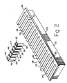
- Fig. 2 is an enlarged perspective view of one configuration of a rack suitable for use with the present automatic random access analyzer, illustrating one embodiment of a reagent package with a plurality of receptacles and containing at least one pre-packaged liquid reagent;
- Fig. 3 is a front elevational view schematically illustrating the shuttle system for incrementally moving the rack for positioning individual reagent packages at the liquid transfer station;
- Fig. 4 is a side elevational view schematically illustrating the shuttle system for transporting a reagent package from the rack to the liquid transfer station and further schematically illustrating the elements of the liquid transfer station and bar-code scanner;
- Fig. 5 is an end view of the reagent package as it appears in fixed position within the liquid transfer station;
- Fig. 6 is a block diagram of the assay formatting computer program for regulating the actions to be performed in the analyzer; and
- Fig. 7 is a flow chart of the scheduler computer program for determining the sequence that reagent packages pass to or through the different operating stations within the present automatic random access analyzer.
- While this invention is satisfied by embodiments in many different forms, there is shown in the drawings and will herein be described in detail a preferred embodiment of the invention, with the understanding that the present disclosure is to be considered as exemplary of the principles of the invention and is not intended to limit the invention to the embodiment illustrated. The scope of the invention will be measured by the appended claims and their equivalents.
- Adverting to the drawings, and Fig. l in particular, there is illustrated a schematic representation of the preferred embodiment of the automatic random access analyzer l0 of the present invention. Enclosing analyzer l0 is a cabinet l2 which holds the major components as illustrated in Fig. l. These major components of the preferred automatic random access analyzer of the present invention are as follows: an introduction station l4, a shuttle system l5, a liquid transfer station l6, an incubation storage area l8, a detection assembly l9 and the
electronics 20 for electrically operating the analyzer as will be described below. A fan 2l is typically included within cabinet l2 for cooling purposes and to permit the components to operate more efficiently. - Introduction station l4 and a
rack 22 for holding a plurality ofreagent packages 24 are illustrated in Figs. l-3. As mentioned above, the present invention does not contemplate storing reagents for the reaction mixtures in bulk containers within the apparatus. Instead, pre-packaged reagents are to be provided for analysis in one or more reagent packages 24. In order to present these reagent packages to the apparatus for subsequent analysis, introduction station l4 is designed to accept the placement ofelongate rack 22 therein. As seen particularly in Fig. 2,rack 22 includes abase 25 and atop plate 26. A series ofslots 28 is formed inrack 22, with the slots aligned in substantially parallel arrangement along the longitudinal axis ofrack 22. Each slot preferably has anopen end 29 and aclosed end 30 for facilitating the proper positioning ofreagent package 24 therein. While sixteen slots are illustrated in the embodiment of Fig. 2, it is understood that the number ofslots 28 may vary according to many factors, including available space, number of reagent packages being utilized, type of tests to be performed, etc. - Each
reagent package 24 includes a substantially planarupper strip 35 and a plurality ofreceptacles slot 28.Strip 35 of the reagent package rests over the slot on top ofplate member 26, thereby holding the reagent package in position in the rack. A square orrectangular wall 44 is preferably included at the end ofreagent package 24 nearend receptacle 42.Wall 44 serves as a keying feature so thatreceptacle 36 must be positioned withinslot 28 so that it lies adjacentclosed end 30. If the reagent package is inserted in the slot in the reverse orientation, however, the bar-code scanner (as described hereinafter) would signal an incorrect insertion. - For purposes of the present apparatus,
receptacle 36 is expected to hold the final reaction mixture for analysis, so that its position in the rack is important as the reagent package is transported from station to station within the apparatus. On the other hand,receptacle 42 is expected to be the container into which the sample to be analyzed is originally placed. To that end,receptacle 42 is preferably left uncovered so that a sample liquid may be introduced throughopening 45 intoreceptacle 42. The remaining receptacles are preferably covered and sealed insofar as one or more of the receptacles may include a pre-packaged liquid reagent therein. In the most preferred form, the cover for the remaining receptacles is a thinprotective sheet 46 sealed over the open ends of the receptacles, exceptreceptacle 42.Sheet 46 is fabricated so as to be readily pierceable by a sharp instrument, as will be described below. In addition,sheet 46 includes information thereon relating to the reagent package, for example, the assay type, expiration date, lot number, serial number, or other information. In the preferable form, this information oncover 46 is in the form of a bar-code which may be read electro-optically for obtaining the information thereon. The details ofreagent package 24 are more completely described in a copending, commonly assigned patent application entitled, "A Self-Contained Reagent Package Device for an Assay," Serial Number 740,593, filed on June 3, l985. - Introduction station l4 preferably includes a
platform 50 or the like for holdingelongate rack 22. This platform is preferably placed at the front or forward part of cabinet l2 so that the rack loaded with reagent packages may be readily positioned in the apparatus by the laboratory technician.Platform 50 should be long enough to accommodate the movement of the rack from one side of the cabinet to the other so that each reagent package passes a position adjacent liquid transfer station l6. -
Rack 22 is translationally moved in incremental steps in front of liquid transfer station l6 by means of shuttle system l5. Shuttle system l5 includes a drive mechanism or a conveyer represented bywheels 5l and 52 as seen in Fig. 3. Associated with these driving wheels are pins ortabs rack 22 translationally across the introduction station. - Driving
mechanisms 5l and 52 may movepins rack 22 and itsreagent packages 24 may be presented to liquid transfer station l6 in any order. Various position detectors may be included on shuttle system l5 to assure proper positioning of the rack and the reagent packages. Similarly, after analysis has been performed by the present apparatus, reagent packages 24 may be returned to the available slots inrack 22 merely by movement of the rack along the introduction platform to accept the used reagent packages. - Referring now to Fig. 4, taken in conjunction with Figs. l and 5, shuttle system l5 includes another drive mechanism for removing one of the reagent packages at a time from the rack and transporting it to liquid transfer station l6. To this end, a
guide rail 58 is positioned so that it extends substantially perpendicular to the longitudinal axis ofrack 24, and substantially parallel toslots 28 within the rack.Guide rail 58 includes atrack 59 which is sized and shaped to accommodatestrip member 35 ofreagent package 24. One or more slidingtabs 60 are associated withtrack 59 and are movable therealong.Movable tabs 60 are adapted to engagestrip member 35 of a reagent package positioned in aslot 28 ofrack 22. Movement oftabs 60, and engagement withstrip member 35, causes the reagent package to slide from the slot of the rack alongtrack 59 until the reagent package enters liquid transfer station l6. It can be seen in Fig. 4 thatguide rail 58 extends betweenrack 22 and the incubation storage area, represented by carousel l8. The shuttle system for transporting the reagent package is designed so that the reagent package may move in either direction betweenrack 22 and carousel l8, and also move back and forth within the liquid transfer station to different positions therein for access to the various receptacles of the reagent package. - Although not shown in Fig. 4 so as not to obscure the details thereof, liquid transfer station l6 includes a feature which is intended to fix the reagent package in position while in the liquid transfer station. As seen in Fig. 5,
reagent package 24 is sandwiched betweenguide rail 58 and aresilient wall 62. This resilient wall may be in the form of a leaf spring or the like sufficient to impart an inwardly directed force againststrip member 35 of the reagent package.Wall 62, however, is also sufficiently resilient so that the reagent package may slide along track betweenguide rail 58 andwall 62. Once the reagent package stops at the liquid transfer station,wall 62, engaged againststrip member 35, provides sufficient gripping action to maintain the position of the reagent package to prevent it from inadvertent sliding or movement. It is appreciated that techniques other than the spring-biased wall, as described in conjunction with Fig. 5, may be utilized for holding the reagent package in position to achieve the intended results. - Fig. 4 also illustrates the presence of a
scanning device 65 which is positioned above the path that reagentpackage 24 slides alongguide rail 58.Scanning device 65 is preferably an electrically operated bar-code scanner for reading the bar-code label as part ofcover 46 ofreagent package 24. Thus, as the reagent package is transported fromrack 22 into liquid transfer station l6, the reagent package passes under bar-code scanner 65 and the information, as described above, contained on the bar-code label is electro-optically read thereby. Accordingly, all of the information contained on the reagent package label is electrically stored in theelectronics 20 of the present random access analyzer. The position of bar-code scanner 65 betweenrack 22 and liquid transfer station l6 facilitates the obtaining of test-related information regarding a reagent package prior to disturbing the protective cover sealed on top of each reagent package. - In the normal analysis of sample liquids, it is preferred to group the various reagent packages into one or more sets. For example, the reagent packages may be grouped into calibrant singlets, calibrant duplicates, control singlets, control duplicates, unknown singlets and unknown duplicates. While bar-
code label 46 on eachreagent package 24 may provide full identification of the reagent package and related test information, the bar-code labels normally do not specify the set into which a specific reagent package should be grouped. Accordingly, instead of a reagent package containing liquid reagents and samples for analysis, rack 22 may include one or more marker packages which resemble a reagent package and are treated no differently by shuttle system l5 and bar-code scanner 65. Each marker package typically includes both machine-readable bar-code and human-readable information to specify reagent package sets, such as listed above. - For each set of reagent packages, there may be a specific marker package. When such markers are used, the laboratory technician normally places a marker package in a
slot 28 ofrack 22, followed by the reagent packages for that set. If more sets are to be placed in the rack, the technician separates the sets with appropriate marker packages. An empty slot or "end of set" marker package indicates that an "unknown" set follows. A marker package label read by bar-code scanner 65 informselectronics 20 that the current set has ended and a new set is ready for processing. If the first slot at the end ofrack 22 does not contain a marker package, then, by default, the first set in the rack is classified as an "unknown." In the normal mode for the present invention,rack 22 is processed from right to left, as viewed in Fig. l. With marker packages placed inrack 22, the technician merely places rack 22 into introduction station l4, designates normal or stat (immediate) processing, and the apparatus automatically commences the tests to be performed on the designated sets. Additional samples and marker packages may subsequently be added to available slots in the rack already placed in the instrument. - Liquid transfer station l6 includes a number of operative elements. These operative elements, a
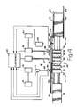
liquid transfer tube 68, apointed punch 70 and awaste tube 72, are positioned abovereagent package 24 and are preferably, but not necessarily, aligned in the arrangement as seen in Fig. 4. Insofar asreagent package 24 is movable, in either direction, along the guide rail within the liquid transfer station, the orientation oftubes - As described above, all of the receptacles, except
receptacle 42, ofreagent package 24 are preferably covered by thinprotective sheet 46.Receptacle 42 is normally left open so that the sample liquid may be introduced therein prior to loading the reagent package into the rack. One or more of the remaining covered receptacles of the reagent package may have liquid reagent therein. In order to gain access to the receptacles, punch 70 is operative to move rapidly downwardly to piercecover 46 and expose the top openings of the receptacles. As will be described more completely hereinafter, the bar-code information on the reagent packages and the marker packages informelectronics 20 of the nature of the processing to be performed; accordingly, punch 70 is controlled by the electronics to punch through the openings of only those receptacles which need to be utilized for the specific assay to be performed. It is appreciated thatreagent package 24 is programmed through the electronics to incrementally move, in either direction, so that any one of the receptacles is positioned underpunch 70 so that the protective cover may be appropriately pierced. Asharp point 74 at the distal end ofpunch 70 facilitates this piercing action. - Once the open ends of the receptacles of
reagent package 24 are exposed by means ofpunch 70, liquid is transferred into, out of or among the different receptacles of the regent package. Such liquid transfer is achieved by virtue ofliquid transfer tube 68 associated with a dual-action pump 76. In one mode, pump 76 aspirates liquid from one or more of the receptacles of the reagent package. Liquid is withdrawn from any one or more of the receptacles throughhollow tube 68, the lumen of which is in fluid communication with areservoir 78. This reservoir is in the fluid path betweentube 68 and pump 76 for the temporary storage of liquid aspirated from one or more of the receptacles. Insofar as reaction mixtures, including the reagent liquids, are preferably heated to an elevated temperature in incubation storage area l8, it is preferred to pre-heat the various liquids which form the liquid reaction mixtures. To this end, aheater 79 is provided to heat the liquid contents of its reservoir to an elevated temperature. For example, the small amounts of liquids which are aspirated intoreservoir 78 may be rapidly heated to a suitable temperature, e.g., 37°C. - In the second mode of dual-
action pump 76, liquid contained inreservoir 78 is pumped out of the reservoir and delivered into one or more receptacles ofreagent package 24. This transfer of liquids fromreservoir 78 into the different receptacles facilitates the mixing of the sample liquid and any liquid reagents originally included in one or more receptacles of the reagent package to thereby form one or more reaction mixtures for subsequent analysis. - In similar fashion as the movement of
punch 70,tube 68 is operative to move up and down so that it travels into and out of any one of the receptacles of the reagent package.Electronics 20 are pre- programmed to regulate the movement ofliquid transfer tube 68 depending upon the test information set forth on the bar-code labels and marker packages. An element which aids in the regulation of volume control may be aliquid level sensor 80 located at or near the distal end ofliquid transfer tube 68. Whentube 68 moves downwardly into one of the receptacles,sensor 80 is capable of detecting the upper level of liquid therein. Not only doessensor 80 contribute to precision in withdrawing and delivering liquids into or out of a receptacle, but this sensor helps to minimize the penetration of the distal end oftube 68 into the liquid. A minimal distance of travel oftube 68 into the liquid means that subsequent rinsing or cleaning of that tube will be easier. Also, control of the penetration oftube 68 into the liquid contributes to minimizing cross-contamination between the various receptacles into whichtube 68 travels. - Rinsing liquid for cleansing
reservoir 78,tube 68 and associated components, is included in a container 8l. Rinsing reagent is pumped out of container 8l by virtue ofpump 76 so that the rinsing liquid is available to cleanse the aforementioned elements, as well as one or more of the receptacles, if so desired. - Further included in liquid transfer station l6 is a
second pump 82 which is operative to withdraw waste liquid from one or more of the receptacles of a reagent package.Hollow tube 72 has its lumen in fluid communication withwithdrawal pump 82. Similar totube 68,hollow tube 72 is pre-programmed to move downwardly into one or more of the receptacles for withdrawing waste liquids out of those receptacles and delivering the waste to awaste container 84. Aliquid level sensor 85 may, if desired, be provided at the distal end oftube 72 for detecting the upper level of liquid in any one of the receptacles from which waste is to be withdrawn. - An example of the operative steps within the liquid transfer station with respect to a single reagent package will now be provided to assist in the understanding of the present invention. A reagent package, such as illustrated in Fig. 2, has a liquid specimen to be assayed deposited in
empty receptacle 42 throughopen end 45. Assuming that blood serum is to be assayed for a determination of trace amounts of proteins, hormones, drugs or the like, the prepared serum is deposited intoreceptacle 42, and the reagent package positioned in the appropriate slot of the rack.Reagent package 24 is transported fromrack 22 into liquid transfer station l6 and, within the liquid transfer station, the reagent package is incrementally stepped so thatpunch 70 piercesprotective cover 46 and exposes the open ends ofreceptacles reagent package 24 is stepped so thatreceptacle 40, with diluent therein, comes directly undertube 68. A measured amount of the diluent is withdrawn fromreceptacle 40 by the action ofpump 76. This measured amount of diluent is temporarily stored inreservoir 78. Next, the reagent package is incrementally moved so thatreceptacle 42 is positioned undertube 68. Prepared serum is withdrawn fromreceptacle 42, and the serum is also temporarily maintained withinreservoir 78, where it may be heated.Receptacle 39, left empty in the original package, is then positioned so that it is directly undertube 68. The measured amount of serum and the diluent within reservoir are then pumped intoempty receptacle 39. The reagent package is subsequently incremented so that receptacle 4l is positioned undertube 68. A tracer material is then withdrawn from receptacle 4l intoreservoir 78. Next, a measured amount of the diluted specimen is withdrawn fromreceptacle 39 throughtube 68 intoreservoir 78.Receptacle 38 is then positioned undertube 68, whereupon the diluted specimen and tracer material fromreservoir 78 are pumped intoreceptacle 38. There, the tracer material reacts with one or more components of the diluted serum. Radioactive, fluorescent and the like materials are typically used as tracers. - At this time an incubation step may be necessary to allow sufficient time for the tracer material to react with the components of the diluted serum. The reagent package with the reaction mixture as described above is then transported out of liquid transfer station l6 into incubation storage area, preferably represented by carousel l8.
Guide rail 58 andtrack 59 extend to carousel l8 so thatreagent package 24 may be deposited into one of theradially extending slots 90 therein.Slots 90 are similar in size and shape toslots 28 ofrack 22, so that a reagent package may be maintained therein, and freely slide in and out when the need for transportation arises. It can be seen particularly by referring to Fig. l that reagentpackage 24 is positioned withinslot 90 so thatreceptacle 42 is at the innermost position, whereasreceptacle 36 is at the outermost position. It is inreceptacle 36 that the reaction mixture is to be analyzed by detector assembly l9. - Carousel l8 is rotatable about a shaft 9l in both clockwise and counterclockwise directions. In this regard, each
slot 90 is positionable with respect to guiderail 58 so that reagent packages may be randomly deposited into carousel l8 or randomly withdrawn therefrom for transportation into or through liquid transfer station l6. Although carousel l8 is illustrated in Fig. l as having an equal number ofslots 90 as the number ofslots 28 inrack 22, the numbers of respective slots may, however, differ. For instance, in one embodiment of the present invention, carousel l8 may contain at least twice the number of slots as there are slots inrack 22 for holding reagent packages. This number of slots in carousel l8 facilitates the handling of more than one rack at a time. One of these slots may be used as a detector calibrator slot. - It is the purpose of carousel l8 to store reagent packages which need to undergo incubation of the different reaction mixtures. Due to the complete random transportation into and out of carousel l8, different reagent packages may be incubated for different times. Accordingly, reagent packages need not, and most frequently are not, positioned in the carousel for sequential movement before detector assembly l9 for analysis. Positioning of the reagent packages before the detector assembly is also done on a random basis according to a pre-programmed schedule, the details of which will be described hereinafter.
- Heating of the reagent packages within carousel l8 is preferably achieved by virtue of a temperature-controlled environment surrounding the carousel. Preferably, but not shown in the drawings, a separate compartment may be provided around carousel l8 with an air bath for maintaining temperature within the compartment at a relatively constant temperature.
- Returning now to the example set forth above, the reagent package was transported into carousel l8 with a reaction mixture within
receptacle 38. After sufficient incubation time in the carousel, the carousel is pre-programmed to rotate so that the slot containing this particular reagent package is aligned with the shuttle system.Reagent package 24 is then moved back into liquid transfer station l6 so thatreceptacle 38 is positioned undertube 68. A measured amount of the reacted mixture inreceptacle 38 is withdrawn and temporarily stored inreservoir 78.Reagent package 24 is then incremented so thatreceptacle 36 is undertube 68. The measured amount of the reacted mixture temporarily held inreservoir 78 is then pumped intoreceptacle 36. A further reaction may take place inreceptacle 36 or the previously reacted mixture may remain the same.Reagent package 24 is then transported back into carousel l8, whereupon further incubation may take place for a period of time, or the reagent package may be scheduled for analysis by detector assembly l9. - Insofar as the present invention is useful for analyzing samples in many different forms, detector assembly l9 may be provided in a variety of different configurations and functions. Many of these different types of analyses were mentioned above. One embodiment of the present invention includes a detector assembly l9 which uses the principle of light energy for conducting the analysis. For example, the reaction mixture in
receptacle 38 may contain fluorescent markers associated with one or more of the components of the sample under investigation. A light source, such as an incandescent lamp, laser or the like, is provided in conjunction with detector assembly l9 to direct light energy intoreceptacle 36 containing the reaction mixture. As pointed out above,receptacle 36 is at the outermost end ofslot 90 in carousel l8 so thatreceptacle 36 is presented in front of detector assembly l9. As light from detector assembly l9 shines throughreceptacle 36, the fluorescent markers in the mixture become excited, and a fluorescence emission occurs. Detection of this fluorescence by an appropriate fluorescence detector, such as a photomultiplier tube or the like, permits the determination of the quantity of a characteristic substance which is present in the sample under analysis. This type of detector assembly facilitates fluoroimmunoassays (FIA) and immunofluorometric assays (IFMA). Different detectors which measure light absorption may also be used in the apparatus. Of course, other assays may be carried out in the present invention, particularly with the use of light energy for conducting the analysis. For instance, nephelometry may be performed by changing the fluorescence detector to a light scatter detector within the detector assembly. It is appreciated that the type of detector assembly for use in the present invention may be selected so as to impart sufficient flexibility for many different types of assays compatible with the present invention. - Regulation of some operative functions of the present automatic random access analyzer is controlled by a computer program l0l as illustrated in Fig. 6. This computer program and the associated computer functions are included in the
electronics 20 of the apparatus. It is the purpose of computer program l0l to provide an interface into the apparatus through which it is possible to define the actions required to process a sample of any particular chemistry type. By virtue of this interface, assays may be formatted for regulating the actions of liquid transfer station l6 for transferring liquid into, out of or among the receptacles ofreagent package 24. As a result of computer program l0l and the interface which it provides, the laboratory technician is free to concentrate on the biological and chemical components of the assay definition, since the apparatus automatically manages the mechanical and electrical functions for carrying out the assays. - As illustrated in Fig. 6, assay data is stored in data files of computer program l0l, and may be subsequently retrieved for performing the tests. This stored data, identified by numeral l02, include the mechanical assay requirements such as the control of electro-mechanical devices, the timing requirements of those devices, reagent package configurations, and other such requirements. In addition to stored data, other data (calibration values, standard values, default control, etc.) may be entered via the keyboard (not shown) associated with the random access analyzer for interface with computer program l0l. Data to be entered, designated by numeral l04, may include chemical assay requirements such as liquid types, liquid locations (i.e., different receptacles), liquid volumes, transfer requirements and the like. It is also feasible to employ a button or switch as a "GO" control for either STAT or normal operation.
- When the present random access analyzer receives a reagent package including a liquid sample of any particular chemistry type, the bar-code label information is read and fed to the electronics for processing by computer program l0l. By retrieving stored data l02 and relying upon STAT or normal data l04, a determination is made as to what actions need to be performed to properly process the liquid sample. This procedure includes the examination of one or more assay templates l05, each of which contains a list of action blocks l06. To process a liquid sample of any particular chemistry, the analyzer performs the actions indicated by each action block in the corresponding assay template. It is preferable to commence the first action in each action block after an indicated incubation period, if any, has passed subsequent to completion of the previous action block. Along these lines, it is also preferable to separate each pair of action blocks in an assay template by an incubation time. Action blocks l06 include a list of actions to be performed by the analyzer along with the time that each action is to begin. In addition, multiple assay templates may specify the same action block. For example, since it is contemplated that all, or most, of the reagent packages would have one of its receptacles analyzed by detector assembly l9, most of the assay templates specify the same final action block, i e , the detection block.
- Other action blocks include the movement of each reagent package into the different positions within the liquid transfer station, the movement of the package into and out of the carousel, positioning of a reagent package adjacent the detector assembly, and transportation of a reagent package back into the rack after the analysis has been completed. Assay templates l05 and action blocks l06 also control the various transfers of liquids into, out of and among the receptacles of a reagent package, in accordance with chemical assay requirements l04 for the analysis of a sample of a particular chemistry type.
- Included in the present automatic random access analyzer is another computer program, or a subroutine of program l0l, associated with
electronics 20 and the operative elements of the analyzer, for scheduling the sequence of events carried out by the analyzer. Fig. 7 represents one embodiment of a flow chart of a scheduler program ll0 for determining the sequence that reagent packages pass, in any order and in any direction, between the rack, the liquid transfer station, the incubation storage area and the detector assembly within the present automatic random access analyzer. Scheduler program ll0 is responsible for examining all of the actions required to complete the processing of the samples which are currently in the apparatus, and arranging them into a sequence which attempts to use the capabilities of the apparatus in an efficient manner. To achieve such an orderly arrangement, the scheduler is programmed to regulate the movements of different reagent packages to and from the various stations of the analyzer. - As the first step of the scheduler program, an examination is made to determine whether there are reagent packages, having samples to be analyzed, presently positioned in the apparatus and which need to be scheduled. If there are no new reagent packages in the apparatus, the scheduler takes no action. When new reagent packages are detected, the following actions are taken in accordance with the preferred scheduling format:
- a. all the reagent packages in the current schedule on which no actions have started are recognized along with new reagent packages in the apparatus;
- b. the total number of reagent packages which need to be scheduled are then identified; and
- c. the identified reagent packages are scheduled.
- In accordance with the preferred embodiment of the present invention, reagent packages are scheduled with the following priorities:
- a. no analyses of samples in stored reagent packages presently underway are to be aborted; processing for reagent packages which already have been started is continued in interrupted fashion;
- b. Stat (immediate) samples in reagent packages are scheduled before all other samples; and
- c. reagent packages which have been in the apparatus for longer than a certain length of time are scheduled before reagent packages which recently have been added.
- Each of these priority groups of samples in reagent packages is extracted, by the computer program, from the total number of samples to be scheduled. Within each group, the more complex samples are placed into the schedule prior to the simpler samples. Complexity is preferably determined by the number of processing or action blocks (such as action blocks l06 described in conjunction with Fig. 6) required to process the sample. For instance, samples with multiple action blocks are scheduled prior to the simpler one or two action block assays. Scheduler ll0 extracts all of the samples from the group that have exactly N action blocks associated with them, with N set to the maximum number of blocks that may occur, as seen in Fig. 7. A resulting list of samples is designated as a schedule plan. The schedule plan is placed into the schedule, N is decremented by one, and the process is repeated until all of the samples in a priority group have been placed in the schedule.
- To perform the scheduling of a schedule plan, the plan is first sorted into scheduling order. Within a plan, the reagent packages with samples having shorter incubation periods are scheduled prior to samples having longer incubation periods. Samples are sorted into the scheduling order, and placed into the schedule one at a time until all the samples in the plan are scheduled. For placement of a sample into the schedule, scheduler ll0 makes use of an expedient referred to as a schedule pointer. This pointer contains the number of the time block at which the first process block of the sample should be started. The schedule pointer is reset to point to the first free time block in the schedule at the start of each priority group. In scheduling a single sample, scheduler ll0 attempts to fit the sample into the schedule at the point indicated by the schedule pointer. If the sample does not fit at that point, the schedule pointer is incremented by one. This process is repeated until the sample fits into the schedule. After fitting the sample into the schedule, the schedule pointer is incremented by N, representing the number of action blocks in the most recently scheduled sample. When all samples have been scheduled, the functions of scheduler program ll0 are completed. The time interval between successive executions of scheduler program ll0 may be preset or may be varied according to choice of the operator depending upon the tests to be conducted.
- Thus, the present invention provides an automated analytical apparatus for the analysis of samples on a totally random access basis. The present invention provides a laboratory technician with considerable flexibility in conducting analyses of samples of different chemistry types. Random access and regulation of the reagent packages of the present invention are handled on an automated basis with particular reliance on computer interface for minimizing manual activities. Since the samples to be analyzed by the present analyzer are included in an self-contained reagent package, construction of the present apparatus is greatly simplified inasmuch as bulk liquid reagents are not required as in presently available clinical analyzers.
Claims (39)
an introduction station for the placement of a rack containing a plurality of reagent packages, each package having a plurality of receptacles at least one of which includes a sample liquid, and at least one of which includes a liquid reagent for forming a reaction mixture with said sample liquid;
a liquid transfer station for the transfer of liquid contained in one or more receptacles of a reagent package among the different receptacles of said one reagent package so that a reaction mixture may be formed;
an incubation storage area for holding a plurality of reagent packages which have passed through said liquid transfer station;
a shuttle system for moving said rack so that each package therein is positionable adjacent said liquid transfer station and for removing one of said packages at a time from the rack and moving it into said transfer station and into said incubation storage area, said shuttle system being further operative to move individual packages from the storage area into said transfer station and into said rack in the introduction station; and
a detector for analyzing the reaction mixture contained in one of the receptacles of any of said packages for determining a characteristic of the sample.
means for receiving a plurality of reagent packages each having a plurality of receptacles at least one of which includes a sample liquid, and at least one of which includes a liquid reagent for forming a reaction mixture with said sample liquid;
means for transferring liquid contained in one or more receptacles of a reagent package to a different receptacle thereof, whereby a reaction mixture may be formed:
detector means for detecting a characteristic of the sample by analyzing the reaction mixture contained in one of the receptacles of a package;
means for storing a plurality of reagent packages; and
means for transporting individual reagent packages in any order and in any direction between the means for receiving, the means for transferring liquid, the detector means and the means for storing.
means for transferring at least one liquid from a receptacle in a package to mix same in a receptacle of said package to form a reaction mixture;
means for detecting a characteristic of the sample by analyzing the reaction mixture in a receptacle of said package;
means for storing a plurality of packages;
means for transporting individual packages in any order and in any direction between the means for transferring, the detecting means and the means for storing; and
control means for regulating the order and direction of transport of individual packages and for transferring the liquids from said receptacles of any one package to form the reaction mixture.
an introduction station for the placement of a rack containing a plurality of reagent packages, each package having a plurality of receptacles at least one of which includes a sample liquid, and at least one of which includes a liquid reagent for forming a reaction mixture with said sample liquid;
a liquid transfer station including a dual action pump for aspirating liquid from one or more receptacles of a single reagent package and for delivering said aspirated liquid into one or more receptacles of said reagent package, said transfer of liquids including the mixing of said sample liquid and said liquid reagent to form a reaction mixture in at least one of the receptacles of said package;
a device for automatically obtaining test related information from the reagent package prior to the transfer of liquids with respect to the receptacles thereof;
means for processing said obtained information for performing the analysis of the reaction mixture, said processing means including means for reading a set marker associated with said rack for identifying the set according to which the reagent packages are positioned in said rack and for performing the analyses in accordance with said set, and further including assay formatting means associated with said liquid transfer station for regulating the actions of said liquid transfer station for transferring liquid into, out of or among the receptacles of the reagent package;
an incubation storage area including a rotatable carousel having a plurality of radially extending slots for the receipt of said reagent packages transported thereto, said carousel being in a temperature-controlled environment for incubating the reagent packages;
a shuttle system for moving said rack so that each package therein is positionable adjacent said liquid transfer station and for removing one of said packages at a time from the rack and moving it into said transfer station and into said carousel, said shuttle system being further operative to move individual packages from the carousel into said transfer station and into said rack in the introduction station;
a detector including a light source for directing light energy into one of the receptacles of the reagent package which contains the reaction mixture for analysis and further including means for receiving light associated with the receptacle into which light energy is directed and for associating said received light with a characteristic of the sample under analysis; and
scheduling means for determining the sequence that reagent packages pass, in any order and in any direction, between the rack, the liquid transfer station, the carousel and the detector.
Priority Applications (1)
| Application Number | Priority Date | Filing Date | Title |
|---|---|---|---|
| MYPI87002208A MY102079A (en) | 1985-11-18 | 1987-09-29 | Automatic random access analyzer |
Applications Claiming Priority (2)
| Application Number | Priority Date | Filing Date | Title |
|---|---|---|---|
| US06/799,238 US4678752A (en) | 1985-11-18 | 1985-11-18 | Automatic random access analyzer |
| US799238 | 1991-11-27 |
Publications (3)
| Publication Number | Publication Date |
|---|---|
| EP0223002A2 true EP0223002A2 (en) | 1987-05-27 |
| EP0223002A3 EP0223002A3 (en) | 1988-06-01 |
| EP0223002B1 EP0223002B1 (en) | 1990-05-09 |
Family
ID=25175388
Family Applications (1)
| Application Number | Title | Priority Date | Filing Date |
|---|---|---|---|
| EP86112609A Expired - Lifetime EP0223002B1 (en) | 1985-11-18 | 1986-09-11 | Automatic random access analyzer |
Country Status (11)
| Country | Link |
|---|---|
| US (1) | US4678752A (en) |
| EP (1) | EP0223002B1 (en) |
| JP (1) | JPS62119460A (en) |
| AU (1) | AU584044B2 (en) |
| BR (1) | BR8604501A (en) |
| CA (1) | CA1273553A (en) |
| DE (1) | DE3671105D1 (en) |
| DK (1) | DK170056B1 (en) |
| MY (1) | MY102079A (en) |
| NZ (1) | NZ217306A (en) |
| ZA (1) | ZA866493B (en) |
Cited By (25)
| Publication number | Priority date | Publication date | Assignee | Title |
|---|---|---|---|---|
| EP0252632A2 (en) * | 1986-07-11 | 1988-01-13 | Beckman Instruments, Inc. | Reagent cartridge |
| EP0325101A1 (en) * | 1988-01-22 | 1989-07-26 | Kabushiki Kaisha Toshiba | Automatic chemical analytical apparatus |
| EP0353589A2 (en) * | 1988-08-02 | 1990-02-07 | Abbott Laboratories | Apparatus and method for providing assay calibration data |
| EP0356250A2 (en) * | 1988-08-25 | 1990-02-28 | Eastman Kodak Company | Analyzers using linear sample trays with random access |
| EP0383322A2 (en) * | 1989-02-17 | 1990-08-22 | Fuji Photo Film Co., Ltd. | Biochemical analysis apparatus,method for correcting the results of biochemical analyses, and correction value recording medium for the same |
| US4970053A (en) * | 1986-07-11 | 1990-11-13 | Beckman Instruments, Inc. | Reagent cartridge |
| EP0449321A2 (en) * | 1990-03-30 | 1991-10-02 | Fujirebio Inc. | Automatic immunological measuring system |
| US5075082A (en) * | 1986-07-11 | 1991-12-24 | Beckman Instruments, Inc. | Reagent cartridge |
| EP0471981A2 (en) * | 1990-07-20 | 1992-02-26 | Johnson & Johnson Clinical Diagnostics, Inc. | Device for transporting containers filled with a liquid |
| WO1993002364A1 (en) * | 1991-07-18 | 1993-02-04 | Pb Diagnostic Systems, Inc. | Assay module transfer apparatus for use in an automated analytical instrument |
| EP0564970A2 (en) * | 1992-04-09 | 1993-10-13 | F. Hoffmann-La Roche Ag | Reagent kit and analyser in which it may be used |
| EP0632271A1 (en) * | 1993-07-01 | 1995-01-04 | Johnson & Johnson Clinical Diagnostics, Inc. | Improved transfer mechanism for automatic loading and unloading of reagent modules |
| EP0632896A1 (en) * | 1992-03-27 | 1995-01-11 | Abbott Laboratories | Automated continuous and random access analytical system |
| EP0634016A1 (en) * | 1992-03-27 | 1995-01-18 | Abbott Laboratories | Assay verification control for analytical methods |
| WO1995008774A2 (en) * | 1993-09-24 | 1995-03-30 | Abbott Laboratories | Automated continuous and random access analytical system and components thereof |
| EP0755519A4 (en) * | 1992-03-27 | 1995-04-07 | Abbott Lab | Automated continuous and random access analytical system and components thereof |
| EP0746769A4 (en) * | 1992-03-27 | 1995-04-07 | Abbott Lab | Automated continuous and random access analytical system and components thereof |
| EP0678746A1 (en) * | 1989-06-23 | 1995-10-25 | Radiometer Medical A/S | Apparatus for analysis of samples of fluids |
| WO1997037218A2 (en) * | 1996-03-29 | 1997-10-09 | Byk Gulden Italia S.P.A. | Automatic diagnostic apparatus |
| WO1999042841A1 (en) | 1998-02-20 | 1999-08-26 | Scil Diagnostics Gmbh | Analysis system |
| EP1618956A2 (en) * | 2004-07-19 | 2006-01-25 | Scil animal care company GmbH | Reagent carrier |
| EP1691201A2 (en) * | 2005-02-09 | 2006-08-16 | Hitachi, Ltd. | Automatic analyzer |
| DE102009051428A1 (en) * | 2009-10-30 | 2011-05-05 | Drg Instruments Gmbh | Reagent cartridge for an assembly to selectively perform a clinical chemistry test or an ELISA test |
| EP2128626A3 (en) * | 2008-05-30 | 2014-11-19 | Grifols, S.A. | Apparatus for the automatic analysis of samples on gel cards |
| CN104215783A (en) * | 2014-05-21 | 2014-12-17 | 凯和生物科技(上海)有限公司 | Strip type immune fully-automatic analyzer |
Families Citing this family (192)
| Publication number | Priority date | Publication date | Assignee | Title |
|---|---|---|---|---|
| CH669851A5 (en) * | 1986-03-06 | 1989-04-14 | Tecan Ag | |
| FR2600166B1 (en) * | 1986-06-17 | 1988-10-07 | Rhone Poulenc Rech | PROCESS AND DEVICE FOR AUTOMATICALLY SUPPORTING AND ANALYZING SAMPLES OF PRODUCTS RANDOMIZED |
| US4855110A (en) * | 1987-05-06 | 1989-08-08 | Abbott Laboratories | Sample ring for clinical analyzer network |
| US4826660A (en) * | 1987-05-07 | 1989-05-02 | Becton, Dickinson And Company | Detector assembly for analyzer instrument |
| US4849177A (en) * | 1987-05-08 | 1989-07-18 | Abbott Laboratories | Reagent pack and carousel |
| JPH01189561A (en) * | 1988-01-25 | 1989-07-28 | Toshiba Corp | Transferring device of sample rack for automatic chemical analysis apparatus |
| US4927765A (en) * | 1988-02-29 | 1990-05-22 | Pharmacia Eni Diagnostics, Inc. | Automatic reagent dispenser |
| US5066135A (en) * | 1988-08-09 | 1991-11-19 | Beckman Instruments, Inc. | Rotatable vortexing turntable |
| US5087423A (en) * | 1988-10-20 | 1992-02-11 | Olympus Optical Co., Ltd. | Automatic analyzing apparatus comprising a plurality of analyzing modules |
| US4960219A (en) * | 1989-09-08 | 1990-10-02 | Abbott Laboratories | Snap cap |
| IE78906B1 (en) * | 1989-12-01 | 1998-03-11 | Akzo Nv | Sample handling system for an optical monitoring system |
| GB9020352D0 (en) * | 1990-09-18 | 1990-10-31 | Anagen Ltd | Assay or reaction apparatus |
| US5595707A (en) | 1990-03-02 | 1997-01-21 | Ventana Medical Systems, Inc. | Automated biological reaction apparatus |
| US5176202A (en) * | 1991-03-18 | 1993-01-05 | Cryo-Cell International, Inc. | Method and apparatus for use in low-temperature storage |
| DE69125797T2 (en) * | 1990-11-28 | 1997-10-09 | Hitachi Ltd | Analysis method and device for liquid samples |
| US6436349B1 (en) * | 1991-03-04 | 2002-08-20 | Bayer Corporation | Fluid handling apparatus for an automated analyzer |
| US6498037B1 (en) * | 1991-03-04 | 2002-12-24 | Bayer Corporation | Method of handling reagents in a random access protocol |
| US5576215A (en) * | 1991-06-03 | 1996-11-19 | Abbott Laboratories | Adaptive scheduling system and method for operating a biological sample analyzer with variable interval periods |
| US5289385A (en) * | 1991-06-03 | 1994-02-22 | Abbott Laboratories | Adaptive scheduling system and method for operating a biological sample analyzer with variable rinsing |
| DE4121089A1 (en) * | 1991-06-26 | 1993-01-07 | Boehringer Mannheim Gmbh | ANALYSIS SYSTEM FOR THE AUTOMATIC ANALYSIS OF BODY LIQUIDS |
| US5696887A (en) | 1991-08-05 | 1997-12-09 | Biotek Solutions, Incorporated | Automated tissue assay using standardized chemicals and packages |
| US5540890A (en) * | 1992-03-27 | 1996-07-30 | Abbott Laboratories | Capped-closure for a container |
| US6190617B1 (en) | 1992-03-27 | 2001-02-20 | Abbott Laboratories | Sample container segment assembly |
| US5610069A (en) * | 1992-03-27 | 1997-03-11 | Abbott Laboratories | Apparatus and method for washing clinical apparatus |
| US5635364A (en) * | 1992-03-27 | 1997-06-03 | Abbott Laboratories | Assay verification control for an automated analytical system |
| US5960160A (en) * | 1992-03-27 | 1999-09-28 | Abbott Laboratories | Liquid heater assembly with a pair temperature controlled electric heating elements and a coiled tube therebetween |
| US5507410A (en) * | 1992-03-27 | 1996-04-16 | Abbott Laboratories | Meia cartridge feeder |
| US5605665A (en) * | 1992-03-27 | 1997-02-25 | Abbott Laboratories | Reaction vessel |
| US5578494A (en) * | 1992-03-27 | 1996-11-26 | Abbott Laboratories | Cap actuator for opening and closing a container |
| US5646049A (en) * | 1992-03-27 | 1997-07-08 | Abbott Laboratories | Scheduling operation of an automated analytical system |
| US5575978A (en) * | 1992-03-27 | 1996-11-19 | Abbott Laboratories | Sample container segment assembly |
| US5627522A (en) * | 1992-03-27 | 1997-05-06 | Abbott Laboratories | Automated liquid level sensing system |
| US5536471A (en) * | 1992-03-27 | 1996-07-16 | Abbott Laboratories | Syringe with bubble flushing |
| US5380487A (en) * | 1992-05-05 | 1995-01-10 | Pasteur Sanofi Diagnostics | Device for automatic chemical analysis |
| US5332549A (en) * | 1992-07-01 | 1994-07-26 | Pb Diagnostic Systems, Inc. | Assay module transport apparatus for use in an automated analytical instrument |
| WO1994001781A1 (en) * | 1992-07-01 | 1994-01-20 | Behring Diagnostics, Inc. | Automated analytical instrument having a fluid sample holding tray transport assembly |
| US5324480A (en) * | 1992-12-04 | 1994-06-28 | Hamilton Company | Liquid handling system |
| US5352612A (en) * | 1993-02-09 | 1994-10-04 | Baxter Diagnostics Inc. | Method and apparatus for the stepwise movement of items |
| CA2156281A1 (en) * | 1993-02-17 | 1994-09-01 | Anthony Hugh Carr | Improvements in or relating to monitoring |
| JP3325338B2 (en) * | 1993-04-27 | 2002-09-17 | プレシジョン・システム・サイエンス株式会社 | Sample test equipment |
| US5681530A (en) * | 1993-06-11 | 1997-10-28 | Ortho Diagnostic Systems Inc. | Transport system for fluid analysis instrument |
| US5578269A (en) * | 1993-06-11 | 1996-11-26 | Ortho Diagnostic Systems Inc. | Automated blood analysis system with an integral centrifuge |
| US5350564A (en) * | 1993-06-28 | 1994-09-27 | Baxter Diagnostics Inc. | Automated chemical analyzer with apparatus and method for conveying and temporary storage of sample tubes |
| US5518693A (en) * | 1994-06-27 | 1996-05-21 | Johnson & Johnson Clinical Diagnostics, Inc. | Transfer mechanism for automatic loading and unloading of reagent modules |
| US5374395A (en) * | 1993-10-14 | 1994-12-20 | Amoco Corporation | Diagnostics instrument |
| US5531959A (en) * | 1994-01-31 | 1996-07-02 | Hamilton Company | Automated liquid handling and computer controlled system and method for solid phase chromatographic extractions |
| FR2711242A1 (en) * | 1994-10-13 | 1995-04-21 | Amoco Corp | Apparatus and method for automatic diagnosis, for analysing samples in multiple test tubes |
| US5492831A (en) * | 1994-11-15 | 1996-02-20 | Lachat Instruments | Shared peripheral analytical system |
| WO1996030767A1 (en) * | 1995-03-27 | 1996-10-03 | Ngk Insulators, Ltd. | Automatic analysis system |
| US6066300A (en) * | 1995-07-07 | 2000-05-23 | Bayer Corporation | Reagent handling system and configurable vial carrier for use therein |
| US5641006A (en) * | 1995-07-13 | 1997-06-24 | Chiron Diagnostics Corporation | Liquid supply apparatus and method of operation |
| US5720377A (en) * | 1995-07-14 | 1998-02-24 | Chiron Diagnostics Corporation | Magnetic conveyor system |
| US5735387A (en) * | 1995-07-14 | 1998-04-07 | Chiron Diagnostics Corporation | Specimen rack handling system |
| US6143250A (en) * | 1995-07-31 | 2000-11-07 | Precision System Science Co., Ltd. | Multi-vessel container for testing fluids |
| US5736102A (en) * | 1996-02-21 | 1998-04-07 | Biomerieux Vitek, Inc. | Test sample positioning system |
| US5670375A (en) * | 1996-02-21 | 1997-09-23 | Biomerieux Vitek, Inc. | Sample card transport method for biological sample testing machine |
| US5824886A (en) * | 1997-01-13 | 1998-10-20 | Tannas Co. | Foam tester |
| GB2311614B (en) * | 1996-03-29 | 2000-04-12 | Byk Gulden Italia Spa | Automatic diagnostic apparatus |
| US5804436A (en) * | 1996-08-02 | 1998-09-08 | Axiom Biotechnologies, Inc. | Apparatus and method for real-time measurement of cellular response |
| US6280967B1 (en) | 1996-08-02 | 2001-08-28 | Axiom Biotechnologies, Inc. | Cell flow apparatus and method for real-time of cellular responses |
| US6558916B2 (en) * | 1996-08-02 | 2003-05-06 | Axiom Biotechnologies, Inc. | Cell flow apparatus and method for real-time measurements of patient cellular responses |
| US5856194A (en) | 1996-09-19 | 1999-01-05 | Abbott Laboratories | Method for determination of item of interest in a sample |
| US5795784A (en) | 1996-09-19 | 1998-08-18 | Abbott Laboratories | Method of performing a process for determining an item of interest in a sample |
| US6009748A (en) * | 1997-01-13 | 2000-01-04 | Tannas Co. | Rapidly cyclable foam testing oven |
| US5853666A (en) * | 1997-02-12 | 1998-12-29 | Biomerieux Vitek, Inc. | Optical reader and sample card transport stations for biological sample testing machine |
| DE19821935A1 (en) * | 1997-05-15 | 1998-11-26 | Tosoh Corp | Immunoanalysis apparatus |
| JPH10319023A (en) * | 1997-05-15 | 1998-12-04 | Tosoh Corp | Vessel holding device |
| USD428497S (en) * | 1998-03-06 | 2000-07-18 | Bayer Corporation | Test tube sample rack |
| EP1614475B1 (en) | 1998-05-01 | 2007-05-30 | Gen-Probe Incorporated | Device for agitating the fluid contents of a container |
| US8337753B2 (en) | 1998-05-01 | 2012-12-25 | Gen-Probe Incorporated | Temperature-controlled incubator having a receptacle mixing mechanism |
| ES2159452B1 (en) * | 1998-05-08 | 2002-04-16 | Probitas Pharma Sa | Clinical analysis centrifugation equipment includes a motorised revolving head with multiple plate type blades and a top guide |
| JP2000046841A (en) * | 1998-07-31 | 2000-02-18 | Tosoh Corp | Automatic measuring apparatus |
| US6413780B1 (en) * | 1998-10-14 | 2002-07-02 | Abbott Laboratories | Structure and method for performing a determination of an item of interest in a sample |
| EP1099950A1 (en) * | 1999-11-12 | 2001-05-16 | F. Hoffmann-La Roche Ag | Analyzer having a rotatable sample rack carrier |
| US6746648B1 (en) * | 2000-06-15 | 2004-06-08 | Beckman Coulter, Inc. | Method and system for transporting and storing multiple reagent packs and reagent packs used therein |
| US20020064881A1 (en) * | 2000-11-30 | 2002-05-30 | Devlin William Jackson | Method for automatically storing and reprocessing patient specimen's in an automatic clinical analyzer |
| EP1355160B1 (en) * | 2001-01-23 | 2013-03-27 | Hitachi, Ltd. | Automatic analyzer |
| US6692700B2 (en) | 2001-02-14 | 2004-02-17 | Handylab, Inc. | Heat-reduction methods and systems related to microfluidic devices |
| US6825041B2 (en) | 2001-03-16 | 2004-11-30 | Beckman Coulter, Inc. | Method and system for automated immunochemistry analysis |
| US8895311B1 (en) | 2001-03-28 | 2014-11-25 | Handylab, Inc. | Methods and systems for control of general purpose microfluidic devices |
| US7829025B2 (en) | 2001-03-28 | 2010-11-09 | Venture Lending & Leasing Iv, Inc. | Systems and methods for thermal actuation of microfluidic devices |
| US6852287B2 (en) | 2001-09-12 | 2005-02-08 | Handylab, Inc. | Microfluidic devices having a reduced number of input and output connections |
| US7010391B2 (en) | 2001-03-28 | 2006-03-07 | Handylab, Inc. | Methods and systems for control of microfluidic devices |
| US7458483B2 (en) * | 2001-04-24 | 2008-12-02 | Abbott Laboratories, Inc. | Assay testing diagnostic analyzer |
| US6588625B2 (en) | 2001-04-24 | 2003-07-08 | Abbott Laboratories | Sample handling system |
| US6838052B2 (en) * | 2001-06-29 | 2005-01-04 | Symyx Technologies, Inc. | In-situ injection and materials screening device |
| US7312084B2 (en) * | 2001-07-13 | 2007-12-25 | Ortho-Clinical Diagnostics, Inc. | Tandem incubator for clinical analyzer |
| US7250303B2 (en) | 2001-07-20 | 2007-07-31 | Ortho-Clinical Diagnostics, Inc. | Chemistry system for a clinical analyzer |
| US6573088B2 (en) * | 2001-08-08 | 2003-06-03 | Dade Microscan Inc. | Automated random access microbiological analyzer |
| US7270785B1 (en) | 2001-11-02 | 2007-09-18 | Ventana Medical Systems, Inc. | Automated molecular pathology apparatus having fixed slide platforms |
| US7303725B2 (en) | 2002-04-15 | 2007-12-04 | Ventana Medical Systems, Inc. | Automated high volume slide staining system |
| US11249095B2 (en) | 2002-04-15 | 2022-02-15 | Ventana Medical Systems, Inc. | Automated high volume slide processing system |
| US7468161B2 (en) | 2002-04-15 | 2008-12-23 | Ventana Medical Systems, Inc. | Automated high volume slide processing system |
| US7378055B2 (en) * | 2002-04-26 | 2008-05-27 | Ventana Medical Systems, Inc. | Automated molecular pathology apparatus having fixed slide platforms |
| WO2004018704A2 (en) * | 2002-05-20 | 2004-03-04 | Northrop Grumman Corporation | Point source biological agent detection system |
| CA2492064C (en) | 2002-06-20 | 2016-03-15 | Vision Biosystems Limited | Biological reaction apparatus with draining mechanism |
| AU2003901871A0 (en) * | 2003-03-31 | 2003-05-08 | Vision Biosystems Limited | A method and apparatus for fluid dispensation, preparation and dilation |
| US7619819B2 (en) * | 2002-08-20 | 2009-11-17 | Illumina, Inc. | Method and apparatus for drug product tracking using encoded optical identification elements |
| US7872804B2 (en) | 2002-08-20 | 2011-01-18 | Illumina, Inc. | Encoded particle having a grating with variations in the refractive index |
| US7900836B2 (en) | 2002-08-20 | 2011-03-08 | Illumina, Inc. | Optical reader system for substrates having an optically readable code |
| US7901630B2 (en) | 2002-08-20 | 2011-03-08 | Illumina, Inc. | Diffraction grating-based encoded microparticle assay stick |
| US7508608B2 (en) | 2004-11-17 | 2009-03-24 | Illumina, Inc. | Lithographically fabricated holographic optical identification element |
| US7164533B2 (en) * | 2003-01-22 | 2007-01-16 | Cyvera Corporation | Hybrid random bead/chip based microarray |
| US7923260B2 (en) | 2002-08-20 | 2011-04-12 | Illumina, Inc. | Method of reading encoded particles |
| EP1535241A1 (en) * | 2002-08-20 | 2005-06-01 | Cyvera Corporation | Diffraction grating-based optical identification element |
| US7441703B2 (en) | 2002-08-20 | 2008-10-28 | Illumina, Inc. | Optical reader for diffraction grating-based encoded optical identification elements |
| EP2261868A2 (en) * | 2002-08-20 | 2010-12-15 | Cyvera Corporation | Diffraction grating-based optical identification element and its applications |
| AU2003267192A1 (en) | 2002-09-12 | 2004-04-30 | Cyvera Corporation | Method and apparatus for aligning elongated microbeads in order to interrogate the same |
| AU2003274979A1 (en) * | 2002-09-12 | 2004-04-30 | Cyvera Corporation | Chemical synthesis using diffraction grating-based encoded optical elements |
| AU2003278827A1 (en) * | 2002-09-12 | 2004-04-30 | Cyvera Corp. | Method and apparatus for labelling using diffraction grating-based encoded optical identification elements |
| WO2004025560A1 (en) * | 2002-09-12 | 2004-03-25 | Cyvera Corporation | Assay stick comprising coded microbeads |
| WO2004025563A1 (en) * | 2002-09-12 | 2004-03-25 | Cyvera Corporation | Diffraction grating-based encoded micro-particles for multiplexed experiments |
| US7092160B2 (en) | 2002-09-12 | 2006-08-15 | Illumina, Inc. | Method of manufacturing of diffraction grating-based optical identification element |
| US20100255603A9 (en) | 2002-09-12 | 2010-10-07 | Putnam Martin A | Method and apparatus for aligning microbeads in order to interrogate the same |
| US7101715B2 (en) * | 2002-09-17 | 2006-09-05 | Dade Behring Inc. | Increasing throughput of an automatic clinical analyzer system by partitioning assays according to frequency of requested performance |
| US7648678B2 (en) | 2002-12-20 | 2010-01-19 | Dako Denmark A/S | Method and system for pretreatment of tissue slides |
| JP3873039B2 (en) | 2003-05-14 | 2007-01-24 | 株式会社日立ハイテクノロジーズ | Automatic analyzer |
| JP3848933B2 (en) * | 2003-05-14 | 2006-11-22 | 株式会社日立ハイテクノロジーズ | Analysis equipment |
| JP4130905B2 (en) * | 2003-06-23 | 2008-08-13 | 株式会社日立ハイテクノロジーズ | Automatic analyzer |
| JP4033060B2 (en) * | 2003-07-17 | 2008-01-16 | 株式会社日立ハイテクノロジーズ | Automatic analyzer |
| WO2005011867A2 (en) | 2003-07-31 | 2005-02-10 | Handylab, Inc. | Processing particle-containing samples |
| US7767152B2 (en) | 2003-08-11 | 2010-08-03 | Sakura Finetek U.S.A., Inc. | Reagent container and slide reaction retaining tray, and method of operation |
| US7744817B2 (en) * | 2003-08-11 | 2010-06-29 | Sakura Finetek U.S.A., Inc. | Manifold assembly |
| US7501283B2 (en) * | 2003-08-11 | 2009-03-10 | Sakura Finetek U.S.A., Inc. | Fluid dispensing apparatus |
| US9518899B2 (en) | 2003-08-11 | 2016-12-13 | Sakura Finetek U.S.A., Inc. | Automated reagent dispensing system and method of operation |
| US7433123B2 (en) | 2004-02-19 | 2008-10-07 | Illumina, Inc. | Optical identification element having non-waveguide photosensitive substrate with diffraction grating therein |
| US8852862B2 (en) | 2004-05-03 | 2014-10-07 | Handylab, Inc. | Method for processing polynucleotide-containing samples |
| US8211386B2 (en) | 2004-06-08 | 2012-07-03 | Biokit, S.A. | Tapered cuvette and method of collecting magnetic particles |
| DE102004054551B4 (en) * | 2004-11-11 | 2021-07-22 | Orgentec Diagnostika Gmbh | Device for the fully automatic implementation of a single immunoassay |
| AU2005307746B2 (en) | 2004-11-16 | 2011-05-12 | Illumina, Inc. | And methods and apparatus for reading coded microbeads |
| WO2006055735A2 (en) | 2004-11-16 | 2006-05-26 | Illumina, Inc | Scanner having spatial light modulator |
| US7604173B2 (en) | 2004-11-16 | 2009-10-20 | Illumina, Inc. | Holographically encoded elements for microarray and other tagging labeling applications, and method and apparatus for making and reading the same |
| CA2599576C (en) | 2005-03-10 | 2015-09-15 | Gen-Probe Incorporated | Systems and methods to perform assays for detecting or quantifying analytes within samples |
| US7670553B2 (en) * | 2005-03-24 | 2010-03-02 | Siemens Healthcare Diagnostics Inc. | Carousel system for automated chemical or biological analyzers employing linear racks |
| US7628954B2 (en) * | 2005-05-04 | 2009-12-08 | Abbott Laboratories, Inc. | Reagent and sample handling device for automatic testing system |
| US7623624B2 (en) | 2005-11-22 | 2009-11-24 | Illumina, Inc. | Method and apparatus for labeling using optical identification elements characterized by X-ray diffraction |
| JP4787026B2 (en) * | 2006-01-20 | 2011-10-05 | 凸版印刷株式会社 | Reaction vessel |
| JP5080740B2 (en) * | 2006-01-20 | 2012-11-21 | 凸版印刷株式会社 | Reaction vessel |
| JP5009531B2 (en) * | 2006-01-20 | 2012-08-22 | 凸版印刷株式会社 | Reaction vessel |
| JP4525624B2 (en) * | 2006-03-23 | 2010-08-18 | 日立化成工業株式会社 | Automatic analyzer |
| US8883490B2 (en) | 2006-03-24 | 2014-11-11 | Handylab, Inc. | Fluorescence detector for microfluidic diagnostic system |
| US11806718B2 (en) | 2006-03-24 | 2023-11-07 | Handylab, Inc. | Fluorescence detector for microfluidic diagnostic system |
| US10900066B2 (en) | 2006-03-24 | 2021-01-26 | Handylab, Inc. | Microfluidic system for amplifying and detecting polynucleotides in parallel |
| WO2007112114A2 (en) | 2006-03-24 | 2007-10-04 | Handylab, Inc. | Integrated system for processing microfluidic samples, and method of using same |
| US7998708B2 (en) * | 2006-03-24 | 2011-08-16 | Handylab, Inc. | Microfluidic system for amplifying and detecting polynucleotides in parallel |
| US7830575B2 (en) | 2006-04-10 | 2010-11-09 | Illumina, Inc. | Optical scanner with improved scan time |
| US8459509B2 (en) | 2006-05-25 | 2013-06-11 | Sakura Finetek U.S.A., Inc. | Fluid dispensing apparatus |
| JP4964518B2 (en) * | 2006-06-30 | 2012-07-04 | 株式会社サカエ | Automatic analyzer |
| JP4980671B2 (en) | 2006-08-18 | 2012-07-18 | シスメックス株式会社 | Blood sample analyzer |
| EP2091647A2 (en) | 2006-11-14 | 2009-08-26 | Handylab, Inc. | Microfluidic system for amplifying and detecting polynucleotides in parallel |
| US8287820B2 (en) | 2007-07-13 | 2012-10-16 | Handylab, Inc. | Automated pipetting apparatus having a combined liquid pump and pipette head system |
| US8133671B2 (en) | 2007-07-13 | 2012-03-13 | Handylab, Inc. | Integrated apparatus for performing nucleic acid extraction and diagnostic testing on multiple biological samples |
| US8105783B2 (en) | 2007-07-13 | 2012-01-31 | Handylab, Inc. | Microfluidic cartridge |
| AU2015210345B2 (en) * | 2007-07-13 | 2017-09-21 | Handylab, Inc. | Integrated apparatus for performing nucleic acid extraction and diagnostic testing on multiple biological samples |
| US9618139B2 (en) | 2007-07-13 | 2017-04-11 | Handylab, Inc. | Integrated heater and magnetic separator |
| US8324372B2 (en) | 2007-07-13 | 2012-12-04 | Handylab, Inc. | Polynucleotide capture materials, and methods of using same |
| US8182763B2 (en) | 2007-07-13 | 2012-05-22 | Handylab, Inc. | Rack for sample tubes and reagent holders |
| US9186677B2 (en) | 2007-07-13 | 2015-11-17 | Handylab, Inc. | Integrated apparatus for performing nucleic acid extraction and diagnostic testing on multiple biological samples |
| USD787087S1 (en) | 2008-07-14 | 2017-05-16 | Handylab, Inc. | Housing |
| US8076126B2 (en) | 2008-07-18 | 2011-12-13 | Ortho-Clinical Diagnostics, Inc. | Single column immunological test elements |
| US8046175B2 (en) | 2008-10-13 | 2011-10-25 | Actherm Inc | Analytical strip reading apparatus and the analyical strip used therein |
| US10184862B2 (en) | 2008-11-12 | 2019-01-22 | Ventana Medical Systems, Inc. | Methods and apparatuses for heating slides carrying specimens |
| WO2010059569A2 (en) * | 2008-11-21 | 2010-05-27 | Monsanto Technology Llc | Analyzers and methods related thereto |
| KR101229160B1 (en) | 2008-12-05 | 2013-02-01 | 액텀 아이엔씨. | A testing piece reader provided with a removable firmware |
| US9108832B2 (en) * | 2009-11-04 | 2015-08-18 | Hitachi High Technologies Corporation | Cover opener and automatic analyzing device using same |
| JP5511336B2 (en) * | 2009-12-01 | 2014-06-04 | 日立アロカメディカル株式会社 | Package rack |
| EP2749887A3 (en) * | 2010-07-23 | 2014-10-01 | Beckman Coulter, Inc. | System Or Method Of Including Analytical Units |
| US9046507B2 (en) | 2010-07-29 | 2015-06-02 | Gen-Probe Incorporated | Method, system and apparatus for incorporating capacitive proximity sensing in an automated fluid transfer procedure |
| US8752732B2 (en) | 2011-02-01 | 2014-06-17 | Sakura Finetek U.S.A., Inc. | Fluid dispensing system |
| US9046504B2 (en) * | 2011-02-24 | 2015-06-02 | Kabushiki Kaisha Toshiba | Automatic analysis apparatus |
| AU2012222178B2 (en) | 2011-02-24 | 2014-12-18 | Gen-Probe Incorporated | Systems and methods for distinguishing optical signals of different modulation frequencies in an optical signal detector |
| WO2012142516A1 (en) | 2011-04-15 | 2012-10-18 | Becton, Dickinson And Company | Scanning real-time microfluidic thermo-cycler and methods for synchronized thermocycling and scanning optical detection |
| US8932543B2 (en) | 2011-09-21 | 2015-01-13 | Sakura Finetek U.S.A., Inc. | Automated staining system and reaction chamber |
| US8580568B2 (en) | 2011-09-21 | 2013-11-12 | Sakura Finetek U.S.A., Inc. | Traceability for automated staining system |
| USD692162S1 (en) | 2011-09-30 | 2013-10-22 | Becton, Dickinson And Company | Single piece reagent holder |
| ES2825905T3 (en) | 2011-09-30 | 2021-05-17 | Becton Dickinson Co | Unified test strip |
| WO2013067202A1 (en) | 2011-11-04 | 2013-05-10 | Handylab, Inc. | Polynucleotide sample preparation device |
| CN107881219B (en) | 2012-02-03 | 2021-09-10 | 贝克顿·迪金森公司 | External file for molecular diagnostic test assignment and compatibility determination between tests |
| AU2013202808B2 (en) | 2012-07-31 | 2014-11-13 | Gen-Probe Incorporated | System and method for performing multiplex thermal melt analysis |
| WO2014144759A1 (en) | 2013-03-15 | 2014-09-18 | Abbott Laboratories | Linear track diagnostic analyzer |
| EP2972219B1 (en) | 2013-03-15 | 2022-01-19 | Abbott Laboratories | Automated reagent manager of a diagnostic analyzer system |
| US9513303B2 (en) | 2013-03-15 | 2016-12-06 | Abbott Laboratories | Light-blocking system for a diagnostic analyzer |
| JP5604551B2 (en) * | 2013-03-27 | 2014-10-08 | 株式会社日立ハイテクノロジーズ | Automatic analyzer |
| EP4095509A1 (en) | 2013-12-13 | 2022-11-30 | Ventana Medical Systems, Inc. | Automated histological processing of biological specimens and associated technology |
| US10031085B2 (en) | 2014-07-24 | 2018-07-24 | Ortho-Clinical Diagnostics, Inc. | Point of care analytical processing system |
| USD814653S1 (en) | 2014-08-07 | 2018-04-03 | Becton, Dickinson And Company | Sample tube holder and components thereof |
| CN107209196B (en) * | 2015-01-23 | 2020-12-08 | 豪夫迈·罗氏有限公司 | Loading device for loading reagent rotor of analytical instrument with reagent containers and analytical instrument |
| CN107167468B (en) * | 2016-03-07 | 2020-01-14 | 重庆科斯迈生物科技有限公司 | Magnetic particle chemiluminescence immunoassay analyzer |
| DE102017005835B4 (en) * | 2017-06-20 | 2020-04-02 | Diehl Metering Gmbh | Device for the mobile determination of a property of a liquid, solid or gaseous sample |
| CN107831325B (en) * | 2017-10-20 | 2021-02-26 | 厦门市波生生物技术有限公司 | Full-automatic chemiluminescence immunoassay analyzer |
| CN109675889A (en) * | 2019-02-20 | 2019-04-26 | 重庆科斯迈生物科技有限公司 | With the chemical illumination immunity analysis instrument washing system for mixing function |
| CN114833141B (en) * | 2022-04-28 | 2024-01-30 | 科来思(深圳)科技有限公司 | Full-automatic chemiluminescence immunoassay analyzer washing module |
Citations (3)
| Publication number | Priority date | Publication date | Assignee | Title |
|---|---|---|---|---|
| US4058367A (en) * | 1976-05-19 | 1977-11-15 | Gilford Instrument Laboratories Inc. | Automatic asynchronous fluid processing apparatus |
| EP0043079A1 (en) * | 1980-06-25 | 1982-01-06 | Electro-Nucleonics, Inc. | Automatic analysis apparatus |
| WO1983000393A1 (en) * | 1981-07-20 | 1983-02-03 | American Hospital Supply Corp | Loading and transfer assembly for chemical analyzer |
Family Cites Families (10)
| Publication number | Priority date | Publication date | Assignee | Title |
|---|---|---|---|---|
| US3582285A (en) * | 1970-03-19 | 1971-06-01 | Xerox Corp | Chemical package |
| CH568793A5 (en) * | 1974-02-15 | 1975-11-14 | Mettler Instrumente Ag | |
| US4054416A (en) * | 1976-08-11 | 1977-10-18 | Secretary Of State For Social Services | Apparatus for use in investigating specimens |
| US3994594A (en) * | 1975-08-27 | 1976-11-30 | Technicon Instruments Corporation | Cuvette and method of use |
| JPS5455494A (en) * | 1977-10-12 | 1979-05-02 | Nippon Tectron Kk | Reagenttfilled reaction tube for automatic chemical analyzer |
| JPS5513552A (en) * | 1978-07-14 | 1980-01-30 | Matsushima Kogyo Co Ltd | Crystal vibrator |
| US4265855A (en) * | 1978-11-03 | 1981-05-05 | Electro-Nucleonics, Inc. | System for performing immunochemical and other analyses involving phase separation |
| US4326851A (en) * | 1980-10-24 | 1982-04-27 | Coulter Electronics, Inc. | Level sensor apparatus and method |
| JPS5774662A (en) * | 1980-10-28 | 1982-05-10 | Fujirebio Inc | Automatic measuring apparatus for enzyme immunity |
| US4595562A (en) * | 1981-07-20 | 1986-06-17 | American Hospital Supply Corporation | Loading and transfer assembly for chemical analyzer |
-
1985
- 1985-11-18 US US06/799,238 patent/US4678752A/en not_active Expired - Fee Related
-
1986
- 1986-08-21 NZ NZ217306A patent/NZ217306A/en unknown
- 1986-08-26 AU AU61835/86A patent/AU584044B2/en not_active Ceased
- 1986-08-27 ZA ZA866493A patent/ZA866493B/en unknown
- 1986-09-04 CA CA000517448A patent/CA1273553A/en not_active Expired - Fee Related
- 1986-09-11 DE DE8686112609T patent/DE3671105D1/en not_active Expired - Fee Related
- 1986-09-11 EP EP86112609A patent/EP0223002B1/en not_active Expired - Lifetime
- 1986-09-19 BR BR8604501A patent/BR8604501A/en not_active IP Right Cessation
- 1986-11-12 JP JP61269486A patent/JPS62119460A/en active Granted
- 1986-11-17 DK DK549286A patent/DK170056B1/en not_active IP Right Cessation
-
1987
- 1987-09-29 MY MYPI87002208A patent/MY102079A/en unknown
Patent Citations (3)
| Publication number | Priority date | Publication date | Assignee | Title |
|---|---|---|---|---|
| US4058367A (en) * | 1976-05-19 | 1977-11-15 | Gilford Instrument Laboratories Inc. | Automatic asynchronous fluid processing apparatus |
| EP0043079A1 (en) * | 1980-06-25 | 1982-01-06 | Electro-Nucleonics, Inc. | Automatic analysis apparatus |
| WO1983000393A1 (en) * | 1981-07-20 | 1983-02-03 | American Hospital Supply Corp | Loading and transfer assembly for chemical analyzer |
Cited By (53)
| Publication number | Priority date | Publication date | Assignee | Title |
|---|---|---|---|---|
| US4970053A (en) * | 1986-07-11 | 1990-11-13 | Beckman Instruments, Inc. | Reagent cartridge |
| EP0252632A3 (en) * | 1986-07-11 | 1989-07-26 | Beckman Instruments, Inc. | Reagent cartridge |
| EP0252632A2 (en) * | 1986-07-11 | 1988-01-13 | Beckman Instruments, Inc. | Reagent cartridge |
| US5075082A (en) * | 1986-07-11 | 1991-12-24 | Beckman Instruments, Inc. | Reagent cartridge |
| EP0325101A1 (en) * | 1988-01-22 | 1989-07-26 | Kabushiki Kaisha Toshiba | Automatic chemical analytical apparatus |
| EP0353589A2 (en) * | 1988-08-02 | 1990-02-07 | Abbott Laboratories | Apparatus and method for providing assay calibration data |
| EP0353589A3 (en) * | 1988-08-02 | 1991-03-13 | Abbott Laboratories | Apparatus and method for providing assay calibration data |
| EP0356250A3 (en) * | 1988-08-25 | 1991-04-24 | Eastman Kodak Company | Analyzers using linear sample trays with random access |
| EP0356250A2 (en) * | 1988-08-25 | 1990-02-28 | Eastman Kodak Company | Analyzers using linear sample trays with random access |
| EP0383322A2 (en) * | 1989-02-17 | 1990-08-22 | Fuji Photo Film Co., Ltd. | Biochemical analysis apparatus,method for correcting the results of biochemical analyses, and correction value recording medium for the same |
| EP0383322A3 (en) * | 1989-02-17 | 1991-04-24 | Fuji Photo Film Co., Ltd. | Biochemical analysis apparatus,method for correcting the results of biochemical analyses, and correction value recording medium for the same |
| EP0678746A1 (en) * | 1989-06-23 | 1995-10-25 | Radiometer Medical A/S | Apparatus for analysis of samples of fluids |
| EP0449321A2 (en) * | 1990-03-30 | 1991-10-02 | Fujirebio Inc. | Automatic immunological measuring system |
| EP0449321A3 (en) * | 1990-03-30 | 1992-09-09 | Fujirebio Inc. | Automatic immunological measuring system |
| EP0471981A2 (en) * | 1990-07-20 | 1992-02-26 | Johnson & Johnson Clinical Diagnostics, Inc. | Device for transporting containers filled with a liquid |
| EP0471981A3 (en) * | 1990-07-20 | 1992-05-27 | Eastman Kodak Company | Device for transporting containers filled with a liquid |
| WO1993002364A1 (en) * | 1991-07-18 | 1993-02-04 | Pb Diagnostic Systems, Inc. | Assay module transfer apparatus for use in an automated analytical instrument |
| EP0634016A4 (en) * | 1992-03-27 | 1997-06-04 | Abbott Lab | Assay verification control for analytical methods. |
| EP0755519A1 (en) * | 1992-03-27 | 1997-01-29 | Abbott Laboratories | Automated continuous and random access analytical system and components thereof |
| EP0746769A1 (en) * | 1992-03-27 | 1996-12-11 | Abbott Laboratories | Automated continuous and random access analytical system and components thereof |
| EP0632896A1 (en) * | 1992-03-27 | 1995-01-11 | Abbott Laboratories | Automated continuous and random access analytical system |
| EP0634016A1 (en) * | 1992-03-27 | 1995-01-18 | Abbott Laboratories | Assay verification control for analytical methods |
| EP0632896A4 (en) * | 1992-03-27 | 1995-03-22 | Abbott Lab | Automated continuous and random access analytical system. |
| EP0755519A4 (en) * | 1992-03-27 | 1995-04-07 | Abbott Lab | Automated continuous and random access analytical system and components thereof |
| EP0746769A4 (en) * | 1992-03-27 | 1995-04-07 | Abbott Lab | Automated continuous and random access analytical system and components thereof |
| US5578272A (en) * | 1992-04-09 | 1996-11-26 | Hoffmann-La Roche Inc. | Reagent kit and analyzer |
| EP0564970A3 (en) * | 1992-04-09 | 1994-05-18 | Hoffmann La Roche | Reagent kit and analyser in which it may be used |
| EP0564970A2 (en) * | 1992-04-09 | 1993-10-13 | F. Hoffmann-La Roche Ag | Reagent kit and analyser in which it may be used |
| AU685709B2 (en) * | 1992-04-09 | 1998-01-22 | F. Hoffmann-La Roche Ag | Automatic analytical apparatus |
| EP0937983A1 (en) * | 1992-04-09 | 1999-08-25 | F. Hoffmann-La Roche Ag | Automatic analyser |
| EP0632271A1 (en) * | 1993-07-01 | 1995-01-04 | Johnson & Johnson Clinical Diagnostics, Inc. | Improved transfer mechanism for automatic loading and unloading of reagent modules |
| EP1028320A2 (en) * | 1993-09-24 | 2000-08-16 | Abbott Laboratories | Method of operating and automated, continuous and random access analytical system capable of simultaneously effecting multiple assays in plurality of liquid samples |
| WO1995008774A2 (en) * | 1993-09-24 | 1995-03-30 | Abbott Laboratories | Automated continuous and random access analytical system and components thereof |
| EP1028320A3 (en) * | 1993-09-24 | 2001-03-14 | Abbott Laboratories | Method of operating an automated, continuous and random access analytical system capable of simultaneously effecting multiple assays in a plurality of liquid samples |
| WO1995008774A3 (en) * | 1993-09-24 | 1995-06-01 | Abbott Lab | Automated continuous and random access analytical system and components thereof |
| WO1997037218A3 (en) * | 1996-03-29 | 1997-11-13 | Byk Gulden Italia Spa | Automatic diagnostic apparatus |
| WO1997037218A2 (en) * | 1996-03-29 | 1997-10-09 | Byk Gulden Italia S.P.A. | Automatic diagnostic apparatus |
| US6866821B2 (en) * | 1996-03-29 | 2005-03-15 | Byk Gulden Italia S.P.A. | Automatic diagnostic apparatus |
| EP2261675A2 (en) | 1998-02-20 | 2010-12-15 | Kabushiki Kaisha Hitachi Seisakusho (Hitachi, Ltd.) | Analysis system |
| WO1999042841A1 (en) | 1998-02-20 | 1999-08-26 | Scil Diagnostics Gmbh | Analysis system |
| US6375898B1 (en) * | 1998-02-20 | 2002-04-23 | Start Diagnostics Gmbh | Analysis system |
| EP2261675A3 (en) * | 1998-02-20 | 2014-04-16 | Kabushiki Kaisha Hitachi Seisakusho (Hitachi, Ltd.) | Analysis system |
| DE19807177A1 (en) * | 1998-02-20 | 1999-09-16 | Scil Animal Care Company Gmbh | Analysis system |
| EP1618956A2 (en) * | 2004-07-19 | 2006-01-25 | Scil animal care company GmbH | Reagent carrier |
| EP1618956A3 (en) * | 2004-07-19 | 2006-05-31 | Scil animal care company GmbH | Reagent carrier |
| EP1691201A3 (en) * | 2005-02-09 | 2007-02-21 | Hitachi, Ltd. | Automatic analyzer |
| EP2282215A1 (en) * | 2005-02-09 | 2011-02-09 | Hitachi, Ltd. | Automatic analyzer |
| US8066959B2 (en) | 2005-02-09 | 2011-11-29 | Hitachi Chemical Company, Ltd. | Automatic analyzer |
| EP1691201A2 (en) * | 2005-02-09 | 2006-08-16 | Hitachi, Ltd. | Automatic analyzer |
| EP2128626A3 (en) * | 2008-05-30 | 2014-11-19 | Grifols, S.A. | Apparatus for the automatic analysis of samples on gel cards |
| DE102009051428A1 (en) * | 2009-10-30 | 2011-05-05 | Drg Instruments Gmbh | Reagent cartridge for an assembly to selectively perform a clinical chemistry test or an ELISA test |
| CN104215783A (en) * | 2014-05-21 | 2014-12-17 | 凯和生物科技(上海)有限公司 | Strip type immune fully-automatic analyzer |
| CN104215783B (en) * | 2014-05-21 | 2015-10-07 | 凯和生物科技(上海)有限公司 | A kind of bar formula immunity fully-automatic analyzer |
Also Published As
| Publication number | Publication date |
|---|---|
| MY102079A (en) | 1992-03-31 |
| DE3671105D1 (en) | 1990-06-13 |
| JPH0564303B2 (en) | 1993-09-14 |
| EP0223002B1 (en) | 1990-05-09 |
| EP0223002A3 (en) | 1988-06-01 |
| CA1273553A (en) | 1990-09-04 |
| DK170056B1 (en) | 1995-05-08 |
| BR8604501A (en) | 1987-11-17 |
| ZA866493B (en) | 1987-04-29 |
| AU6183586A (en) | 1987-05-21 |
| JPS62119460A (en) | 1987-05-30 |
| AU584044B2 (en) | 1989-05-11 |
| NZ217306A (en) | 1989-01-06 |
| DK549286D0 (en) | 1986-11-17 |
| DK549286A (en) | 1987-05-19 |
| US4678752A (en) | 1987-07-07 |
Similar Documents
| Publication | Publication Date | Title |
|---|---|---|
| US4678752A (en) | Automatic random access analyzer | |
| US5316726A (en) | Automated immunoassay analyzer with pictorial display of assay information | |
| US4224032A (en) | Method and apparatus for chemical analysis | |
| US9134332B2 (en) | Instrument and process for the automated processing of liquid samples | |
| EP1465728B1 (en) | Stackable aliquot vessel array | |
| US4608231A (en) | Self-contained reagent package device for an assay | |
| US8003050B2 (en) | Device for analyzing samples | |
| CA1099951A (en) | Automatic chemical analysis of biological fluids | |
| US7256045B2 (en) | Analyzer with sample quality measurement, and method | |
| EP1681569A2 (en) | Assay testing diagnostic analyzer | |
| EP0628824A1 (en) | Transport system for fluid analysis instrument | |
| US7101715B2 (en) | Increasing throughput of an automatic clinical analyzer system by partitioning assays according to frequency of requested performance | |
| JP2008534924A (en) | Carousel system for automated chemical or biological analyzers using linear racks | |
| CN101218493A (en) | Automated method for preparing whole blood sample analysis and automated device therefor | |
| EP1102994A2 (en) | Automated immunoassay apparatus with flexible pick-up arm | |
| US20090129979A1 (en) | Clinical analyzer having a variable cycle time and throughput | |
| JPH01187461A (en) | Automatic chemical analyzer | |
| CN218727352U (en) | Sample analyzer | |
| EP0549759B1 (en) | Assay module transfer apparatus for use in an automated analytical instrument | |
| US20020064884A1 (en) | Method for automatically storing and reprocessing patient specimen's in an automatic clinical analyzer | |
| JP2598806B2 (en) | Dispensing device | |
| JPH0354472A (en) | Method of controlling biochemical analyzer | |
| JPH0566558U (en) | Simple automatic analyzer |
Legal Events
| Date | Code | Title | Description |
|---|---|---|---|
| PUAI | Public reference made under article 153(3) epc to a published international application that has entered the european phase |
Free format text: ORIGINAL CODE: 0009012 |
|
| AK | Designated contracting states |
Kind code of ref document: A2 Designated state(s): BE CH DE FR GB IT LI NL SE |
|
| PUAL | Search report despatched |
Free format text: ORIGINAL CODE: 0009013 |
|
| AK | Designated contracting states |
Kind code of ref document: A3 Designated state(s): BE CH DE FR GB IT LI NL SE |
|
| 17P | Request for examination filed |
Effective date: 19881116 |
|
| 17Q | First examination report despatched |
Effective date: 19890206 |
|
| GRAA | (expected) grant |
Free format text: ORIGINAL CODE: 0009210 |
|
| AK | Designated contracting states |
Kind code of ref document: B1 Designated state(s): BE CH DE FR GB IT LI NL SE |
|
| REF | Corresponds to: |
Ref document number: 3671105 Country of ref document: DE Date of ref document: 19900613 |
|
| ET | Fr: translation filed | ||
| ITF | It: translation for a ep patent filed |
Owner name: ING. C. GREGORJ S.P.A. |
|
| PLBE | No opposition filed within time limit |
Free format text: ORIGINAL CODE: 0009261 |
|
| STAA | Information on the status of an ep patent application or granted ep patent |
Free format text: STATUS: NO OPPOSITION FILED WITHIN TIME LIMIT |
|
| 26N | No opposition filed | ||
| ITTA | It: last paid annual fee | ||
| EAL | Se: european patent in force in sweden |
Ref document number: 86112609.2 |
|
| PGFP | Annual fee paid to national office [announced via postgrant information from national office to epo] |
Ref country code: GB Payment date: 19960902 Year of fee payment: 11 |
|
| PGFP | Annual fee paid to national office [announced via postgrant information from national office to epo] |
Ref country code: FR Payment date: 19960910 Year of fee payment: 11 |
|
| PGFP | Annual fee paid to national office [announced via postgrant information from national office to epo] |
Ref country code: SE Payment date: 19960917 Year of fee payment: 11 |
|
| PGFP | Annual fee paid to national office [announced via postgrant information from national office to epo] |
Ref country code: CH Payment date: 19960919 Year of fee payment: 11 |
|
| PGFP | Annual fee paid to national office [announced via postgrant information from national office to epo] |
Ref country code: DE Payment date: 19960920 Year of fee payment: 11 |
|
| PGFP | Annual fee paid to national office [announced via postgrant information from national office to epo] |
Ref country code: NL Payment date: 19960930 Year of fee payment: 11 |
|
| PGFP | Annual fee paid to national office [announced via postgrant information from national office to epo] |
Ref country code: BE Payment date: 19961118 Year of fee payment: 11 |
|
| PG25 | Lapsed in a contracting state [announced via postgrant information from national office to epo] |
Ref country code: GB Free format text: LAPSE BECAUSE OF NON-PAYMENT OF DUE FEES Effective date: 19970911 |
|
| PG25 | Lapsed in a contracting state [announced via postgrant information from national office to epo] |
Ref country code: SE Free format text: LAPSE BECAUSE OF NON-PAYMENT OF DUE FEES Effective date: 19970912 |
|
| PG25 | Lapsed in a contracting state [announced via postgrant information from national office to epo] |
Ref country code: LI Free format text: LAPSE BECAUSE OF NON-PAYMENT OF DUE FEES Effective date: 19970930 Ref country code: FR Free format text: THE PATENT HAS BEEN ANNULLED BY A DECISION OF A NATIONAL AUTHORITY Effective date: 19970930 Ref country code: CH Free format text: LAPSE BECAUSE OF NON-PAYMENT OF DUE FEES Effective date: 19970930 Ref country code: BE Free format text: LAPSE BECAUSE OF NON-PAYMENT OF DUE FEES Effective date: 19970930 |
|
| BERE | Be: lapsed |
Owner name: BECTON DICKINSON & CY Effective date: 19970930 |
|
| PG25 | Lapsed in a contracting state [announced via postgrant information from national office to epo] |
Ref country code: NL Free format text: LAPSE BECAUSE OF NON-PAYMENT OF DUE FEES Effective date: 19980401 |
|
| GBPC | Gb: european patent ceased through non-payment of renewal fee |
Effective date: 19970911 |
|
| REG | Reference to a national code |
Ref country code: CH Ref legal event code: PL |
|
| NLV4 | Nl: lapsed or anulled due to non-payment of the annual fee |
Effective date: 19980401 |
|
| PG25 | Lapsed in a contracting state [announced via postgrant information from national office to epo] |
Ref country code: DE Free format text: LAPSE BECAUSE OF NON-PAYMENT OF DUE FEES Effective date: 19980603 |
|
| EUG | Se: european patent has lapsed |
Ref document number: 86112609.2 |
|
| REG | Reference to a national code |
Ref country code: FR Ref legal event code: ST |
|
| PG25 | Lapsed in a contracting state [announced via postgrant information from national office to epo] |
Ref country code: IT Free format text: LAPSE BECAUSE OF NON-PAYMENT OF DUE FEES;WARNING: LAPSES OF ITALIAN PATENTS WITH EFFECTIVE DATE BEFORE 2007 MAY HAVE OCCURRED AT ANY TIME BEFORE 2007. THE CORRECT EFFECTIVE DATE MAY BE DIFFERENT FROM THE ONE RECORDED. Effective date: 20050911 |