EP0223340B2 - Electrode for a living body - Google Patents
Electrode for a living body Download PDFInfo
- Publication number
- EP0223340B2 EP0223340B2 EP86306507A EP86306507A EP0223340B2 EP 0223340 B2 EP0223340 B2 EP 0223340B2 EP 86306507 A EP86306507 A EP 86306507A EP 86306507 A EP86306507 A EP 86306507A EP 0223340 B2 EP0223340 B2 EP 0223340B2
- Authority
- EP
- European Patent Office
- Prior art keywords
- electrode
- lead
- living body
- main body
- defibrillator
- Prior art date
- Legal status (The legal status is an assumption and is not a legal conclusion. Google has not performed a legal analysis and makes no representation as to the accuracy of the status listed.)
- Expired - Lifetime
Links
- 0 C(*1)C2C1CCC2 Chemical compound C(*1)C2C1CCC2 0.000 description 1
- GDOPTJXRTPNYNR-UHFFFAOYSA-N CC1CCCC1 Chemical compound CC1CCCC1 GDOPTJXRTPNYNR-UHFFFAOYSA-N 0.000 description 1
Images


Classifications
-
- A—HUMAN NECESSITIES
- A61—MEDICAL OR VETERINARY SCIENCE; HYGIENE
- A61N—ELECTROTHERAPY; MAGNETOTHERAPY; RADIATION THERAPY; ULTRASOUND THERAPY
- A61N1/00—Electrotherapy; Circuits therefor
- A61N1/02—Details
- A61N1/04—Electrodes
- A61N1/0404—Electrodes for external use
- A61N1/0408—Use-related aspects
- A61N1/046—Specially adapted for shock therapy, e.g. defibrillation
-
- A—HUMAN NECESSITIES
- A61—MEDICAL OR VETERINARY SCIENCE; HYGIENE
- A61N—ELECTROTHERAPY; MAGNETOTHERAPY; RADIATION THERAPY; ULTRASOUND THERAPY
- A61N1/00—Electrotherapy; Circuits therefor
- A61N1/02—Details
- A61N1/04—Electrodes
- A61N1/0404—Electrodes for external use
- A61N1/0472—Structure-related aspects
- A61N1/0492—Patch electrodes
-
- A—HUMAN NECESSITIES
- A61—MEDICAL OR VETERINARY SCIENCE; HYGIENE
- A61N—ELECTROTHERAPY; MAGNETOTHERAPY; RADIATION THERAPY; ULTRASOUND THERAPY
- A61N1/00—Electrotherapy; Circuits therefor
- A61N1/02—Details
- A61N1/04—Electrodes
- A61N1/0404—Electrodes for external use
- A61N1/0408—Use-related aspects
Description
- This invention relates to an electrode for a living body which is suitable for a defibrillator, an electrocardiograph, or the like.
- In the process of a cardiac catheterization, a catheter is inserted into a blood vessel of a patient to inject a contrast media for X-ray inspection. There is, however, the case that the patient's heart is convulsed for more than 15 to 30 seconds due to an excitation in the middle of the inspection. If the convulsion of the heart continues for a long time, it causes damage to brain cells through interruptions of blood flow. Accordingly, when such a convulsion of the heart arises, in general, a high-voltage shock of 3000 to 5000 volts is given to the heart with a defibrillator.
- Such a conventional defibrillator has generally a box-shaped body provided with a handle at the upper surface of the body. The defibrillator is provided with electrodes at the lower surface of the body. The electrodes are to be brought into contact with a patient's body at the portion over his heart to give an electric shock to the heart.
- Such a conventional defibrillator is, however, very troublesome because it must be brought out to be used whenever the patient's heart is convulsed. Especially, there is the possibility that it is not in time for the case of emergency.
- Besides, on several occasions, the electrodes of an electrocardiograph must be attached to the surface of a patient's body for getting electrocardiograms at the time of an X-ray inspection. But, because the electrodes of such an electrocardiograph are conventionally made of metal and they are not transparent in regard to X rays, they are hindrances to X-ray photographing. X-ray transparent electrodes are known from US-A-4 442 315, these being in laminate form.
- Accordingly, it is an object of the present invention to provide an electrode for a living body which is substantially transparent to X rays so as not to hinder any X-ray inspection.
- Advantageously, the eletrode can serve both as electrodes of an electrocardiograph and a defibrillator.
- According to the present invention there is provided an electrode for a living body comprising a main body which consists of a flexible sheet of graphite having a thickness in the range of 0.1 to 2.0 mm and a minimum permissible radius of curvature less than 50 mm, and a lead attached thereto, the electrode body being flexible and the whole of the electrode being substantially transparent to X-rays.
- The invention will be further described, by way of example with reference to the drawings, in which:
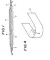
- Fig. 1 is a cross-sectional view showing an electrode of a defibrillator according to an embodiment of the invention;
- Figs. 2A and 2B are perspective views of electrodes with lead portions;
- Figs. 3A and 3B are a side view and a plan view showing a manner of use of the defibrillator; and
- Fig. 4 is a perspective view for illustrating the flexibility of a graphite sheet.
- Hereinafter, embodiments in which the present invention is applied to the electrodes of a defibrillator will be described with reference to attached drawings.
- Referring first to Figs. 3A and 3B, a defibrillator comprises a high-voltage source 1, a pair of electrode body (hereinafter, each merely called "electrode") 2, and leads 3 for connecting the electrodes to the high-voltage source. Each
electrode 2 consists of a disk-like flexible sheet (see Figs. 2A and 2B) having area of about 50 cm2 and the thickness of about 0.1 to 2 mm. Theelectrodes 2 are attached to a patient'sbody 4 from both of the breast side and the back side of his heart, respectively. As shown in Figs. 1, 3A and 3B, eachelectrode 2 is directly attached to the patient's skin with a proper adhesive and fixed with adhesive tapes orbands 5. As the present case, when the electrodes serve as that of a defibrillator, they must be fixed in an especially firm manner because they are apt to come off from the patient's body due to a high-voltage shock. - Referring to Fig. 1, a ring-shaped sponge 7 is arranged around the
electrode 2. Aprotective layer 8 is disposed on the upper surface of theelectrode 2. As shown by imaginary lines in Fig. 1, abuffer 9 such as a sponge containting physiological sodium chloride solution may be interposed between theelectrode 2 and a living body in order to improve the affinity with and the followability to the living body and the absorbability of a high-voltage shock. - Each
electrode 2 is made of a crystalline flexible sheet of graphite obtained by treating natural graphite particles with concentrated sulfuric acid of 98%. For example, it can be made of Grafoil (Registered trade name) available by Union Carbide Corp. - The thickness t of the
electrode 2 preferably falls within the range of 0.1 of 2 mm more preferably within the range of 0.2 to 1 mm. If the thickness t is less than 0.1 mm, the mechanical strength of the electrode decreases, while, if the thickness t is more than 2 mm, the flexibility of the electrode decreases. - As shown in Fig. 4, the flexibility of a graphite sheet 6 to be used as an electrode can be represented by the permissible minimum radius R of curvature when the sheet is bent. In the present device, the radius R is preferably less than 100 mm, more preferably less than 50 mm. If the radius R is more than 100 mm, the flexibility required can not be obtained so the followability to a living body lowers and the manner of contact with the living body becomes bad. As the result, the electrode become easy to come off from the living body by a high-voltage shock or the like.
- In addition, particularly in the case of the electrodes of a defibrillator, since a high voltage (3000 to 5000 volts) is applied to and a large current flows through them, the electrical resistance of each electrode is preferably less than 1.0 ohm. If the resistance is too large, the electrode may cause a burn on a living body due to the generation of heat.
- Each
lead 3 of the defibrillator may be made of a graphite sheet such as Grafoil, similarly to theelectrode 2. Figs. 2A and 2B show examples that thelead 3 is made of Grafoil. In the example shown in Fig. 2B, theelectrode 2 andlead 3 are integral, that is they are formed from a single sheet of graphite. - Grafoil can be easily formed into any shape by punching or the like so it is superior in mass productivity. In addition, Grafoil can make the contact resistance between the lead and the electrode decrease to a value which may be disregarded.
- The
electrode 2 and thelead 3 can be bonded to each other with an electroconductive adhesive that powder of carbon black is mixed in a thermosetting resin. The thermosetting resin usable is, for example, phenolic resin, epoxy resin, etc. The content of carbon black is preferably 30 to 90wt. %. If the content of carbon black is too little, the electrical conductivity required can not be obtained, while, if the content is too much, the adhesive strength decreases. - Agso an electroconductive adhesive that powder of carbon black is mixed in a rubber adhesive can be used. In that case, either of a natural rubber adhesive or a synthetic rubber adhesive can be used. The content of carbon black is preferably 30 to 90 wt.% from the same reason as described above. An electroconductive adhesive of this type can make the connecting portion between the electrode and the lead flexible though the adhesive strength may decrease.
- Alternatively, the following method can be employed for connecting the
electrode 2 and thelead 3 to each other. That is, after theelectrode 2 and thelead 3 are connected to each other with an adhesive that powder of carbon black is mixed in a thermosetting resin, the connecting portion is calcined and carbonized under a reduced pressure or in an inert atmosphere at a temperature not less than 1000°C. By this method, the electrical resistance of the connecting portion decreases to a value which may be disregarded. The thermosetting resin usable for this method is, for example, phenolic resin, epoxy resin, etc. The content of carbon black is preferably less than 90 wt. %. If the content of carbon black is too much, the adhesive strength decreases. - In the above-mentioned configuration, both of the
electrodes 2 and theleads 3 are substantially transparent in regard to X rays. Therefore, they are not hindrances to X-ray photographing. As the result, the electrode can be attached to a patient's body through an X-ray inspection. - In the present device, also a lead made of carbon fibers can be used. In that case, however, the connecting manner of the lead to an electrode may become difficult. In addition, there are disadvantages that the electrical resistance increases and the lead becomes bulky. The above-mentioned
lead 3 of Grafoil can solve all of those problems. - In the above-mentioned embodiments, the present invention is applied to the electrodes of a defibrillator. The present invention, however, can be applied also to the electrodes of an electrocardiograph. In addition, an electrode of the present invention can serve both as electrode of a defibrillator and an electrocardiograph. Furthermore, the present invention can be applied to various electrodes such as that of a electroencephalograph and so on.
- In the present invention, the main body of an electrode consists of a flexible sheet of graphite and the whole of the electrode is substantially transparent in regard to X rays. Therefore, the electrode is not a hindrance to X-ray photographing. As the result, it can be applied to the electrodes of an electrocardiograph or a defibrillator attached to a living body through an X-ray inspection. In addition, in the present invention since the surface of an electrode to contact with a living body is made flexible, the followability to the living body is superior so the electrode is hard to come off from the living body even when it is used as an electrode of a defibrillator.
Claims (5)
Applications Claiming Priority (2)
| Application Number | Priority Date | Filing Date | Title |
|---|---|---|---|
| JP187596/85 | 1985-08-27 | ||
| JP60187596A JPS6247373A (en) | 1985-08-27 | 1985-08-27 | X-ray permeable living body electrode |
Publications (3)
| Publication Number | Publication Date |
|---|---|
| EP0223340A1 EP0223340A1 (en) | 1987-05-27 |
| EP0223340B1 EP0223340B1 (en) | 1990-11-22 |
| EP0223340B2 true EP0223340B2 (en) | 1994-10-19 |
Family
ID=16208874
Family Applications (1)
| Application Number | Title | Priority Date | Filing Date |
|---|---|---|---|
| EP86306507A Expired - Lifetime EP0223340B2 (en) | 1985-08-27 | 1986-08-21 | Electrode for a living body |
Country Status (5)
| Country | Link |
|---|---|
| US (1) | US4800887A (en) |
| EP (1) | EP0223340B2 (en) |
| JP (1) | JPS6247373A (en) |
| CA (1) | CA1287664C (en) |
| DE (1) | DE3675738D1 (en) |
Families Citing this family (9)
| Publication number | Priority date | Publication date | Assignee | Title |
|---|---|---|---|---|
| DK283789A (en) * | 1988-10-05 | 1990-04-06 | Niels Kornerup | ELECTRIC GENERATOR, COMPRESS AND COMPRESSION COMBINATION AND SYSTEM FOR THE TREATMENT OF ELECTRIC STIMULATION AND PROCEDURE FOR THE TREATMENT OF SARS |
| US5366497A (en) * | 1992-03-31 | 1994-11-22 | Cardiotronics, Inc. | Non-invasive, radiolucent cardiac electrode |
| US5356428A (en) * | 1992-03-31 | 1994-10-18 | Cardiotronics, Inc. | Non-invasive, radiolucent electrode |
| DE4232255C1 (en) * | 1992-09-25 | 1994-02-17 | Siemens Ag | Neutral electrode and method for reusing it for a high-frequency surgical device with application monitoring device |
| US5571165A (en) * | 1995-12-08 | 1996-11-05 | Ferrari; R. Keith | X-ray transmissive transcutaneous stimulating electrode |
| US5733324A (en) * | 1995-12-08 | 1998-03-31 | Ferrari; R. Keith | X-ray transmissive transcutaneous stimulating electrode |
| US7774070B2 (en) * | 2008-01-10 | 2010-08-10 | Hill Laboratories Company | Medical electrode assembly for electrotherapy and phototherapy treatment |
| US9226680B1 (en) | 2013-02-12 | 2016-01-05 | David Kendricks | Patient electrode connectors for electrocardiograph monitoring system |
| CN107049302A (en) * | 2017-06-26 | 2017-08-18 | 美合实业(苏州)有限公司 | Cardiac diagnosis lead-line |
Family Cites Families (14)
| Publication number | Priority date | Publication date | Assignee | Title |
|---|---|---|---|---|
| AU1388870A (en) * | 1969-05-02 | 1971-10-21 | Sybron Corporation | Inactive electrode |
| GB1298010A (en) * | 1970-11-19 | 1972-11-29 | ||
| JPS528633B2 (en) * | 1971-12-13 | 1977-03-10 | ||
| GB1542859A (en) * | 1975-12-18 | 1979-03-28 | Nat Res Dev | Electrode assemblies |
| US4102331A (en) * | 1976-09-21 | 1978-07-25 | Datascope Corporation | Device for transmitting electrical energy |
| CA1111503A (en) * | 1977-04-02 | 1981-10-27 | Isoji Sakurada | Biomedical electrode |
| US4248237A (en) * | 1978-03-07 | 1981-02-03 | Needle Industries Limited | Cardiac pacemakers |
| US4198991A (en) * | 1978-05-17 | 1980-04-22 | Cordis Corporation | Cardiac pacer lead |
| DE2842318C2 (en) * | 1978-09-28 | 1985-05-23 | Siemens AG, 1000 Berlin und 8000 München | Implantable carbon electrode |
| US4257424A (en) * | 1979-04-30 | 1981-03-24 | Ndm Corporation | X-ray transparent medical electrode |
| US4370984A (en) * | 1979-04-30 | 1983-02-01 | Ndm Corporation | X-Ray transparent medical electrode |
| US4417581A (en) * | 1979-05-23 | 1983-11-29 | The University Of Florida | Corneal electrode for electroretinography |
| US4442315A (en) * | 1980-11-17 | 1984-04-10 | Fukuda Denshi Kabushiki Kaisha | X-Ray transmissive electrode-shielded wire assembly and manufacture thereof |
| FR2548028B1 (en) * | 1983-06-15 | 1986-09-19 | Hovelian Krikor | DISPOSABLE SURFACE MEDICAL ELECTRODE |
-
1985
- 1985-08-27 JP JP60187596A patent/JPS6247373A/en active Pending
-
1986
- 1986-08-21 EP EP86306507A patent/EP0223340B2/en not_active Expired - Lifetime
- 1986-08-21 DE DE8686306507T patent/DE3675738D1/en not_active Expired - Fee Related
- 1986-08-26 CA CA000516803A patent/CA1287664C/en not_active Expired - Fee Related
- 1986-08-26 US US06/900,661 patent/US4800887A/en not_active Expired - Fee Related
Also Published As
| Publication number | Publication date |
|---|---|
| CA1287664C (en) | 1991-08-13 |
| EP0223340A1 (en) | 1987-05-27 |
| US4800887A (en) | 1989-01-31 |
| EP0223340B1 (en) | 1990-11-22 |
| JPS6247373A (en) | 1987-03-02 |
| DE3675738D1 (en) | 1991-01-03 |
Similar Documents
| Publication | Publication Date | Title |
|---|---|---|
| US4748983A (en) | X-ray transmissive electrode for a living body | |
| US4715382A (en) | Flat biomedical electrode with reuseable lead wire | |
| US4852571A (en) | Disposable biopotential electrode | |
| US4570637A (en) | Electrode | |
| JP5430832B2 (en) | Medical electrode | |
| EP0767692B1 (en) | Vented electrode | |
| US5356428A (en) | Non-invasive, radiolucent electrode | |
| US5337748A (en) | Biosignal electrode | |
| US5824033A (en) | Multifunction electrode | |
| ES2370475T3 (en) | X-RAY TRANSMITTER TRANSCUTANEOUS STIMULATOR ELECTRODE. | |
| EP1424094B1 (en) | X-ray transmissive transcutaneous stimulating electrode | |
| AU644916B2 (en) | Medical electrode assembly | |
| JP2001506154A (en) | Biomedical electrodes with disposable electrodes and reusable lead adapters that interface with standard lead connectors | |
| WO1981001646A1 (en) | Medical electrode construction and method of assembly | |
| EP0223340B2 (en) | Electrode for a living body | |
| US6898465B2 (en) | Differential gel body for a medical stimulation electrode | |
| EP0222473A1 (en) | Electrode for a living body | |
| US6477430B1 (en) | Hands-free paddles using single-use adhesive pads | |
| EP0269200A1 (en) | Flat biomedical electrode | |
| CN211962036U (en) | Electrode structure and biological information monitoring system | |
| JPS6247375A (en) | X-ray permeable living body electrode | |
| JPS62122677A (en) | X-ray pervious living body electrode | |
| EP0375440B1 (en) | An electrode for use on living tissue |
Legal Events
| Date | Code | Title | Description |
|---|---|---|---|
| PUAI | Public reference made under article 153(3) epc to a published international application that has entered the european phase |
Free format text: ORIGINAL CODE: 0009012 |
|
| AK | Designated contracting states |
Kind code of ref document: A1 Designated state(s): DE FR GB |
|
| 17P | Request for examination filed |
Effective date: 19871112 |
|
| 17Q | First examination report despatched |
Effective date: 19891010 |
|
| GRAA | (expected) grant |
Free format text: ORIGINAL CODE: 0009210 |
|
| AK | Designated contracting states |
Kind code of ref document: B1 Designated state(s): DE FR GB |
|
| REF | Corresponds to: |
Ref document number: 3675738 Country of ref document: DE Date of ref document: 19910103 |
|
| ET | Fr: translation filed | ||
| PLBI | Opposition filed |
Free format text: ORIGINAL CODE: 0009260 |
|
| 26 | Opposition filed |
Opponent name: SIEMENS AKTIENGESELLSCHAFT, BERLIN UND MUENCHEN Effective date: 19910528 |
|
| PLBI | Opposition filed |
Free format text: ORIGINAL CODE: 0009260 |
|
| 26 | Opposition filed |
Opponent name: HORN GMBH & CO. KG Effective date: 19910822 Opponent name: SIEMENS AKTIENGESELLSCHAFT, BERLIN UND MUENCHEN Effective date: 19910528 |
|
| PUAH | Patent maintained in amended form |
Free format text: ORIGINAL CODE: 0009272 |
|
| STAA | Information on the status of an ep patent application or granted ep patent |
Free format text: STATUS: PATENT MAINTAINED AS AMENDED |
|
| 27A | Patent maintained in amended form |
Effective date: 19941019 |
|
| AK | Designated contracting states |
Kind code of ref document: B2 Designated state(s): DE FR GB |
|
| ET3 | Fr: translation filed ** decision concerning opposition | ||
| PGFP | Annual fee paid to national office [announced via postgrant information from national office to epo] |
Ref country code: FR Payment date: 19960809 Year of fee payment: 11 |
|
| PGFP | Annual fee paid to national office [announced via postgrant information from national office to epo] |
Ref country code: GB Payment date: 19960812 Year of fee payment: 11 |
|
| PGFP | Annual fee paid to national office [announced via postgrant information from national office to epo] |
Ref country code: DE Payment date: 19960830 Year of fee payment: 11 |
|
| PG25 | Lapsed in a contracting state [announced via postgrant information from national office to epo] |
Ref country code: GB Free format text: LAPSE BECAUSE OF NON-PAYMENT OF DUE FEES Effective date: 19970821 |
|
| GBPC | Gb: european patent ceased through non-payment of renewal fee |
Effective date: 19970821 |
|
| PG25 | Lapsed in a contracting state [announced via postgrant information from national office to epo] |
Ref country code: FR Free format text: LAPSE BECAUSE OF NON-PAYMENT OF DUE FEES Effective date: 19980430 |
|
| PG25 | Lapsed in a contracting state [announced via postgrant information from national office to epo] |
Ref country code: DE Free format text: LAPSE BECAUSE OF NON-PAYMENT OF DUE FEES Effective date: 19980501 |
|
| REG | Reference to a national code |
Ref country code: FR Ref legal event code: ST |
|
| PLAB | Opposition data, opponent's data or that of the opponent's representative modified |
Free format text: ORIGINAL CODE: 0009299OPPO |