EP0223729A1 - Torque control for a variable speed wind turbine - Google Patents
Torque control for a variable speed wind turbine Download PDFInfo
- Publication number
- EP0223729A1 EP0223729A1 EP86630169A EP86630169A EP0223729A1 EP 0223729 A1 EP0223729 A1 EP 0223729A1 EP 86630169 A EP86630169 A EP 86630169A EP 86630169 A EP86630169 A EP 86630169A EP 0223729 A1 EP0223729 A1 EP 0223729A1
- Authority
- EP
- European Patent Office
- Prior art keywords
- speed
- torque
- generator
- rotor
- power
- Prior art date
- Legal status (The legal status is an assumption and is not a legal conclusion. Google has not performed a legal analysis and makes no representation as to the accuracy of the status listed.)
- Granted
Links
- 238000000034 method Methods 0.000 claims abstract description 9
- 238000010586 diagram Methods 0.000 description 3
- 230000007423 decrease Effects 0.000 description 2
- 230000003247 decreasing effect Effects 0.000 description 2
- 230000002411 adverse Effects 0.000 description 1
- 238000012888 cubic function Methods 0.000 description 1
- 230000000694 effects Effects 0.000 description 1
- 238000010304 firing Methods 0.000 description 1
- RLQJEEJISHYWON-UHFFFAOYSA-N flonicamid Chemical compound FC(F)(F)C1=CC=NC=C1C(=O)NCC#N RLQJEEJISHYWON-UHFFFAOYSA-N 0.000 description 1
- 238000009434 installation Methods 0.000 description 1
- 230000000452 restraining effect Effects 0.000 description 1
Images

Classifications
-
- H—ELECTRICITY
- H02—GENERATION; CONVERSION OR DISTRIBUTION OF ELECTRIC POWER
- H02P—CONTROL OR REGULATION OF ELECTRIC MOTORS, ELECTRIC GENERATORS OR DYNAMO-ELECTRIC CONVERTERS; CONTROLLING TRANSFORMERS, REACTORS OR CHOKE COILS
- H02P5/00—Arrangements specially adapted for regulating or controlling the speed or torque of two or more electric motors
-
- F—MECHANICAL ENGINEERING; LIGHTING; HEATING; WEAPONS; BLASTING
- F03—MACHINES OR ENGINES FOR LIQUIDS; WIND, SPRING, OR WEIGHT MOTORS; PRODUCING MECHANICAL POWER OR A REACTIVE PROPULSIVE THRUST, NOT OTHERWISE PROVIDED FOR
- F03D—WIND MOTORS
- F03D7/00—Controlling wind motors
- F03D7/02—Controlling wind motors the wind motors having rotation axis substantially parallel to the air flow entering the rotor
- F03D7/022—Adjusting aerodynamic properties of the blades
- F03D7/0224—Adjusting blade pitch
-
- F—MECHANICAL ENGINEERING; LIGHTING; HEATING; WEAPONS; BLASTING
- F03—MACHINES OR ENGINES FOR LIQUIDS; WIND, SPRING, OR WEIGHT MOTORS; PRODUCING MECHANICAL POWER OR A REACTIVE PROPULSIVE THRUST, NOT OTHERWISE PROVIDED FOR
- F03D—WIND MOTORS
- F03D7/00—Controlling wind motors
- F03D7/02—Controlling wind motors the wind motors having rotation axis substantially parallel to the air flow entering the rotor
- F03D7/0272—Controlling wind motors the wind motors having rotation axis substantially parallel to the air flow entering the rotor by measures acting on the electrical generator
-
- H—ELECTRICITY
- H02—GENERATION; CONVERSION OR DISTRIBUTION OF ELECTRIC POWER
- H02P—CONTROL OR REGULATION OF ELECTRIC MOTORS, ELECTRIC GENERATORS OR DYNAMO-ELECTRIC CONVERTERS; CONTROLLING TRANSFORMERS, REACTORS OR CHOKE COILS
- H02P9/00—Arrangements for controlling electric generators for the purpose of obtaining a desired output
- H02P9/42—Arrangements for controlling electric generators for the purpose of obtaining a desired output to obtain desired frequency without varying speed of the generator
-
- F—MECHANICAL ENGINEERING; LIGHTING; HEATING; WEAPONS; BLASTING
- F05—INDEXING SCHEMES RELATING TO ENGINES OR PUMPS IN VARIOUS SUBCLASSES OF CLASSES F01-F04
- F05B—INDEXING SCHEME RELATING TO WIND, SPRING, WEIGHT, INERTIA OR LIKE MOTORS, TO MACHINES OR ENGINES FOR LIQUIDS COVERED BY SUBCLASSES F03B, F03D AND F03G
- F05B2220/00—Application
- F05B2220/70—Application in combination with
- F05B2220/706—Application in combination with an electrical generator
-
- F—MECHANICAL ENGINEERING; LIGHTING; HEATING; WEAPONS; BLASTING
- F05—INDEXING SCHEMES RELATING TO ENGINES OR PUMPS IN VARIOUS SUBCLASSES OF CLASSES F01-F04
- F05B—INDEXING SCHEME RELATING TO WIND, SPRING, WEIGHT, INERTIA OR LIKE MOTORS, TO MACHINES OR ENGINES FOR LIQUIDS COVERED BY SUBCLASSES F03B, F03D AND F03G
- F05B2270/00—Control
- F05B2270/10—Purpose of the control system
- F05B2270/1016—Purpose of the control system in variable speed operation
-
- F—MECHANICAL ENGINEERING; LIGHTING; HEATING; WEAPONS; BLASTING
- F05—INDEXING SCHEMES RELATING TO ENGINES OR PUMPS IN VARIOUS SUBCLASSES OF CLASSES F01-F04
- F05B—INDEXING SCHEME RELATING TO WIND, SPRING, WEIGHT, INERTIA OR LIKE MOTORS, TO MACHINES OR ENGINES FOR LIQUIDS COVERED BY SUBCLASSES F03B, F03D AND F03G
- F05B2270/00—Control
- F05B2270/10—Purpose of the control system
- F05B2270/103—Purpose of the control system to affect the output of the engine
- F05B2270/1032—Torque
-
- F—MECHANICAL ENGINEERING; LIGHTING; HEATING; WEAPONS; BLASTING
- F05—INDEXING SCHEMES RELATING TO ENGINES OR PUMPS IN VARIOUS SUBCLASSES OF CLASSES F01-F04
- F05B—INDEXING SCHEME RELATING TO WIND, SPRING, WEIGHT, INERTIA OR LIKE MOTORS, TO MACHINES OR ENGINES FOR LIQUIDS COVERED BY SUBCLASSES F03B, F03D AND F03G
- F05B2270/00—Control
- F05B2270/10—Purpose of the control system
- F05B2270/20—Purpose of the control system to optimise the performance of a machine
-
- F—MECHANICAL ENGINEERING; LIGHTING; HEATING; WEAPONS; BLASTING
- F05—INDEXING SCHEMES RELATING TO ENGINES OR PUMPS IN VARIOUS SUBCLASSES OF CLASSES F01-F04
- F05B—INDEXING SCHEME RELATING TO WIND, SPRING, WEIGHT, INERTIA OR LIKE MOTORS, TO MACHINES OR ENGINES FOR LIQUIDS COVERED BY SUBCLASSES F03B, F03D AND F03G
- F05B2270/00—Control
- F05B2270/30—Control parameters, e.g. input parameters
- F05B2270/327—Rotor or generator speeds
-
- H—ELECTRICITY
- H02—GENERATION; CONVERSION OR DISTRIBUTION OF ELECTRIC POWER
- H02P—CONTROL OR REGULATION OF ELECTRIC MOTORS, ELECTRIC GENERATORS OR DYNAMO-ELECTRIC CONVERTERS; CONTROLLING TRANSFORMERS, REACTORS OR CHOKE COILS
- H02P2101/00—Special adaptation of control arrangements for generators
- H02P2101/15—Special adaptation of control arrangements for generators for wind-driven turbines
-
- Y—GENERAL TAGGING OF NEW TECHNOLOGICAL DEVELOPMENTS; GENERAL TAGGING OF CROSS-SECTIONAL TECHNOLOGIES SPANNING OVER SEVERAL SECTIONS OF THE IPC; TECHNICAL SUBJECTS COVERED BY FORMER USPC CROSS-REFERENCE ART COLLECTIONS [XRACs] AND DIGESTS
- Y02—TECHNOLOGIES OR APPLICATIONS FOR MITIGATION OR ADAPTATION AGAINST CLIMATE CHANGE
- Y02E—REDUCTION OF GREENHOUSE GAS [GHG] EMISSIONS, RELATED TO ENERGY GENERATION, TRANSMISSION OR DISTRIBUTION
- Y02E10/00—Energy generation through renewable energy sources
- Y02E10/70—Wind energy
- Y02E10/72—Wind turbines with rotation axis in wind direction
Definitions
- This invention relates to wind turbines, and particularly to a torque control for a variable speed wind turbine which operates the wind turbine at improved efficiencies.
- the object of the present invention is to increase the efficiency of a variable speed wind turbine generator.
- the torque is still held constant; however, the rotor speed is allowed to increase at a faster rate than if constant velocity ratio operation had been continued as in the prior art.
- This may be done by controlling to a constant torque level and allowing rotor speed to increase in a manner which maintains optimal performance.
- the power is allowed to increase above the limiting torque at a rate greater than the rate that would be obtained if constant velocity ratio operation were used, as in the prior art.
- the power increases until a speed or power limit is reached, as in the prior art. However, this level is reached at a lower wind speed than in the prior art.
- the velocity ratio increases as the rotor speed increases above the limiting torque.
- the optimum power ratio and therefore power will be achieved by following the rotor performance envelope for all velocity ratios until a power and/or rotational speed limit is reached.
- the power ratio will decrease slightly from the maximum point at which it was operating during constant velocity ratio operation.
- the present invention teaches a new design philosophy for a variable speed wind turbine generator in which additional power may be recovered above the wind speed where the turbine-generator torque limit is reached by increasing rotor speed at a faster rate than dictated by constant velocity ratio operation. Maximum possible power is extracted while maintaining the preset torque limit.
- the annual increase in energy output from a wind turbine-generator using the design philosophy disclosed herein is on the order of approximately 5% over the prior art.
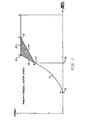
- Fig. I is a plot of the power output from a variable speed wind turbine-generator against wind speed. Below a selected speed 10, corresponding to the limiting torque of the particular wind turbine gearbox, the turbine is operated with a constant velocity ratio (blade tip speed over wind speed) as indicated by the locus of points 11 between points A 12 and B 13. From A to B the torque is proportional to the square of the wind speed and the output power is proportional to the cube of the wind speed. Thus, the locus of points II from A to B is a cubic function corresponding to the power output of the generator.
- the prior art design philosophy for a variable speed wind turbine generator limits the torque to a constant value above wind speeds at which the limiting torque is achieved (as is necessarily also the case in the present invention) and the velocity ratio is held constant at speeds above the limiting torque whereby the rotor speed varies linearly with wind speed.
- the power also increases linearly with wind speed as shown by the locus of points 14 from point B 13 to point D 15 in Fig. I.
- the prior art method of holding torque constant while still increasing power above the torque limit is to make moderate blade pitch angle or yaw heading changes from points B to D.
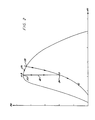
- FIG. 2 shows a plot of maximum power ratio versus velocity ratio for a particular rotor.
- the power ratio (PR) is defined as the actual power output of the wind turbine divided by the power provided by the wind. In other words, the power ratio represents the efficiency of the wind turbine rotor in extracting the available power provided to it by the wind.
- the velocity ratio (VR) is the tip speed of the rotor divided by the wind speed.
- FIG. 2 is illustrative of a point of maximum constant power ratio and constant velocity ratio corresponding to operation on the curve II of Fig. from points A 12 to B 13.
- the restraining torque which counteracts the rotor torque, is controlled through the generator to maintain a fixed ratio between rotor rotational speed and incoming wind speed. This torque control maintains a fixed velocity ratio at the rotor performance peak. This is shown schematically in Figure 2 at point A-B 20.
- Fig. 2 The prior art method of running speed up above the torque limit, from points B 13 to D 15 along the locus of points 14 in Fig. I, is illustrated in Fig. 2 as a path 22 of decreasing power ratio at constant velocity ratio from point A-B 20 to a point D 24 corresponding to point D 15 of Fig. I.
- the power ratio is decreased only a small amount according to the present invention, instead of the corresponding large amount of change in power ratio, according to the prior art.
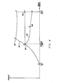
- the rotor rotational speed (N ROTOR ) on shaft 41 will follow the rotor characteristics shown in Figure 2 to balance the input power supplied by the wind to the rotor 43.
- a gearbox 45 is shown to increase the rotor speed on shaft 41 to the generator speed (N GEN ) sensed by the sensor 47 on shaft 49. This speed increase produces a torque (QSHAFT2), which is a fraction of the rotor torque by the gearbox ratio, on shaft 49 that is to be reacted bv the generator 40.
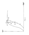
- rotor thrust forces increase rapidly from point B 80 to C 82.
- Path 84 corresponds to the locus of points 34 of Fig. I.
- This increased thrust has some adverse effects on the economic improvements expected from this mode of operation.
- the path from B to C increases thrust very rapidly.
- the prior art (described as CVR operation above), on the other hand, shows a slump in thrust forces once a limit torque is reached (along a path 86 from point B 80 to point D, corresponding to the locus of points 14 of Fig. I).
- a path B 80-F 90 can be selected in which the thrust is held constant while maintaining constant torque.
Abstract
Description
- The invention described herein may employ some of the teachings disclosed and claimed in commonly owned co-pending application having United States Serial No. (Attorney Docket HI311-WE), filed on the same day as this application, invented by Doman et al, entitled A VARIABLE SPEED WIND TURBINE, which is hereby expressly incorporated by reference.
- This invention relates to wind turbines, and particularly to a torque control for a variable speed wind turbine which operates the wind turbine at improved efficiencies.
- The prior art design philosophy for a variable speed wind turbine generator uses the following approach:
- I) Constant Velocity Ratio (CVR) Variable Speed Operation Below A Limiting Torque. During this phase of operation, rotor speed is linearly proportional to the wind speed. Torque increases as the square of the wind speed and power increases as the cube of the wind speed. The pitch angle (for a variable pitch propeller) or yaw angle (for a fixed pitch propeller) is held constant.
- 2) CVR Variable Speed Operation Above a Limiting Torque. Above the wind speed at which a torque limit is reached the torque is held constant, the velocity ratio is held constant, and the rotor speed varies linearly with wind speed. The power also increases linearly with the wind speed. The blade pitch angle, or yaw heading, is modulated to hold torque constant.
- 3) Constant Power Operation. When a rotor speed and/or power limit is reached, power is held constant by holding rotor speed and torque constant using active pitch or yaw control.
- The object of the present invention is to increase the efficiency of a variable speed wind turbine generator.
- According to the present invention, above the wind speed at which a preset torque limit is reached, the torque is still held constant; however, the rotor speed is allowed to increase at a faster rate than if constant velocity ratio operation had been continued as in the prior art. This may be done by controlling to a constant torque level and allowing rotor speed to increase in a manner which maintains optimal performance. Thus, the power is allowed to increase above the limiting torque at a rate greater than the rate that would be obtained if constant velocity ratio operation were used, as in the prior art. The power increases until a speed or power limit is reached, as in the prior art. However, this level is reached at a lower wind speed than in the prior art. Thought of in terms of rotor performance, according to the present invention, the velocity ratio increases as the rotor speed increases above the limiting torque.
- While controlling to a constant torque, the optimum power ratio and therefore power will be achieved by following the rotor performance envelope for all velocity ratios until a power and/or rotational speed limit is reached. Thus, while the velocity ratio increases, the power ratio will decrease slightly from the maximum point at which it was operating during constant velocity ratio operation.
- The present invention teaches a new design philosophy for a variable speed wind turbine generator in which additional power may be recovered above the wind speed where the turbine-generator torque limit is reached by increasing rotor speed at a faster rate than dictated by constant velocity ratio operation. Maximum possible power is extracted while maintaining the preset torque limit. The annual increase in energy output from a wind turbine-generator using the design philosophy disclosed herein is on the order of approximately 5% over the prior art.
- These and other objects, features and advantages of the present invention will become more apparent in light of the detailed description of a best mode embodiment thereof, as illustrated in the accompanying drawing.
- Brief Description Of The Drawing
- Fig. I is an illustration of a power v. wind speed curve which illustrates various variable speed wind turbine operating options, including operation dictated according to the present invention;
- Fig. 2 is an illustration of a particular wind turbine rotor performance map showing the variable speed operating options illustrated in Fig. I in a non-dimensional format;
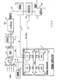
- Fig. 3 is a simplified schematic block diagram illustration of a wind turbine-generator control for a variable speed generator;
- Fig. 4 is an illustration of a plot of thrust versus wind speed;
- Fig. 5 is an illustration of a plot of thrust versus velocity ratio; and
- Fig. 6 is a simplified schematic block diagram illustration of a variable speed wind turbine in which the teachings of the present invention may be incorporated.
- Fig. I is a plot of the power output from a variable speed wind turbine-generator against wind speed. Below a selected speed 10, corresponding to the limiting torque of the particular wind turbine gearbox, the turbine is operated with a constant velocity ratio (blade tip speed over wind speed) as indicated by the locus of points 11 between
points A 12 and B 13. From A to B the torque is proportional to the square of the wind speed and the output power is proportional to the cube of the wind speed. Thus, the locus of points II from A to B is a cubic function corresponding to the power output of the generator. - As discussed in the Background Art section, the prior art design philosophy for a variable speed wind turbine generator limits the torque to a constant value above wind speeds at which the limiting torque is achieved (as is necessarily also the case in the present invention) and the velocity ratio is held constant at speeds above the limiting torque whereby the rotor speed varies linearly with wind speed. Thus, in the prior art, the power also increases linearly with wind speed as shown by the locus of points 14 from point B 13 to
point D 15 in Fig. I. Whereas the blade pitch angle and yaw heading is held constant from points A to B, the prior art method of holding torque constant while still increasing power above the torque limit is to make moderate blade pitch angle or yaw heading changes from points B to D. At point D, where a rotor speed and/or power limit is reached, power is held constant by holding rotor speed and torque constant using more significant pitch or yaw heading changes, i.e., using more active pitch or yaw control. At point E, the cut-out wind speed is reached and the pitch or yaw angle is changed to bring the rotor to a stop. - Referring now to Fig. 2, an illustration is provided of a performance map for a wind turbine rotor showing the contrast between variable speed operation according to the prior art and according to the present invention. Fig. 2 shows a plot of maximum power ratio versus velocity ratio for a particular rotor. Depending on the particular rotor blade chord distribution, twist distribution, thickness distribution, etc., the performance curve will vary among rotor types significantly. The power ratio (PR) is defined as the actual power output of the wind turbine divided by the power provided by the wind. In other words, the power ratio represents the efficiency of the wind turbine rotor in extracting the available power provided to it by the wind. The velocity ratio (VR) is the tip speed of the rotor divided by the wind speed. The rotor performance map holds true for certain blade shapes and will of course change depending on particular types of rotors, as mentioned above. A
point 20 is shown in Fig. 2 which is illustrative of a point of maximum constant power ratio and constant velocity ratio corresponding to operation on the curve II of Fig. frompoints A 12 to B 13. Thus, by operating along the locus of points II of Fig. I, one obtains maximum efficiency by correspondingly staying atpoint 20 in Fig. 2. The restraining torque, which counteracts the rotor torque, is controlled through the generator to maintain a fixed ratio between rotor rotational speed and incoming wind speed. This torque control maintains a fixed velocity ratio at the rotor performance peak. This is shown schematically in Figure 2 atpoint A-B 20. The prior art method of running speed up above the torque limit, from points B 13 toD 15 along the locus of points 14 in Fig. I, is illustrated in Fig. 2 as a path 22 of decreasing power ratio at constant velocity ratio frompoint A-B 20 to a point D 24 corresponding topoint D 15 of Fig. I. As will be seen from the teachings of the present invention, it is a better idea to extract more power by operating above the torque limit along apath 26 on the optimum performance curve from point A-B 20 to apoint C 28. In this way, the power ratio is decreased only a small amount according to the present invention, instead of the corresponding large amount of change in power ratio, according to the prior art. - Thus, referring back to Fig. I, operation from point B 13 at the torque limit to a
point C 33 along a locus ofpoints 34, instead of along the locus of points 14, is taught by the present invention. This operation is accomplished by commanding a constant torque restraint at the generator and allowing the rotor speed to increase in relation to the incoming wind speed at a faster rate than below the limiting torque. This mode allows the velocity ratio to increase while keeping the rotor at higher power ratios and maintaining a constant torque. Upon reaching a power or speed limit at point C, rotor speed is not increased any further and the power remains constant from point C to point D along a path 35 and on to point E, as in the prior art. Thus, the shaded area BCD of Fig. I is proportional to the additional energy captured by a wind turbine-generator operated according to the present invention. - Fig. 3 is an illustration of a wind turbine-generator control system for a variable speed generator, in which the present invention may be implemented a described below.
- Below the torque limit of the wind turbine-generator, the control of Fig. 3 operates in a mode which controls generator torque by means of a
generator torque control 40. Above the torque limit, arotor control 42 takes over and controls rotor speed by means of pitch changes. Whereas in the prior art, pitch change was effected above the torque limit so as to keep the tip speed of the rotor constant with respect to the wind speed, thereby increasing power linearly, theaerodynamic rotor control 42, according to the present invention, is operating at a constant angle or changing very slightly to maintain maximum power output. The rotor speed will increase according to the performance envelope of Figure 2 to maintain the power ratio vs. velocity ratio relation of the rotor. - An aerodynamic torque (QSHAFT1) on the rotor shaft 41, created by the wind impinging on the rotor 43, is reacted through an opposing torque (OE) supplied by a variable speed torque-controlled
generator 40. The rotor rotational speed (NROTOR) on shaft 41 will follow the rotor characteristics shown in Figure 2 to balance the input power supplied by the wind to the rotor 43. Agearbox 45 is shown to increase the rotor speed on shaft 41 to the generator speed (NGEN) sensed by thesensor 47 on shaft 49. This speed increase produces a torque (QSHAFT2), which is a fraction of the rotor torque by the gearbox ratio, on shaft 49 that is to be reacted bv thegenerator 40. - Below a limiting torque a schedule 44 is responsive to a sensed output power signal on a
line 46 indicative of the level of electrical power being delivered by the generator. The schedule provides a generator speed reference signal online 48 to a dynamictorque control unit 50 which is responsive to the difference between the speed reference signal online 48 and the generator speed signal online 51. The speed error is dynamically adjusted through thecontrol 50 by commanding changes in generator torque online 52. Thegenerator 40 responds to the commanded torque and brings the generator speed and power to convergence according to schedule 44 which includes the constant torque region described in Figure 2 by the locus ofpoints 26. The torque produced by the generator through therotor 53 reacts with the turbine shaft 41 torque to maintain a fixed rotor speed in relation to wind speed. - A
generator speed comparator 55 shifts control of the pitch or yaw angle (β) depending on the status of present generator speed. At generator speeds below the maximum allowed generator speed, a schedule 54 is followed. In the region below the limiting torque, is held constant with thetorque control 50 maintaining rotor speed according to schedule 44. - At wind speeds above the limiting torque and rotor speeds below maximum allowable speed, is varied to maintain optimum power as a function of the rotor speed while maintaining a constant torque according to schedule 54. For a pitch-controlled turbine the output of the schedule control 54 (βREF) on
line 57, is transmitted to the rotor control which commands pitch angle actuators to actuate linkages shown by aline 59 to move the rotor to the desired position. For a yaw control turbine the output of schedule 54 remains constant for optimum power. - When the generator speed reaches the maximum limit on the system, either due to structural or performance considerations, the speed comparator switches control to an
angle controller 56 which maintains constant speed. Thecontroller 56 compares the actual generator speed to maximum speed and commands a pitch or yaw angle which will maintain constant rotor speed. A βREF signal is transmitted fromcontroller 56 alongline 57 to therotor control 42 which commands the pitch or yaw actuators to move the rotor to the desired position. Power remains constant at this constant rotor signal since torque is also maintained at the limiting torque value. - Thus, it will be understood by those skilled in the art that the illustration of Figure 3, including circuitry and variable speed generator electrical components can be made to carry out the teachings of the present invention. Although Fig. 3 has been shown using various functional blocks and schedules, as an aid to understanding the teachings of the present invention, it will be understood that the control functions illustrated will normally be carried out by a digital embodiment including a signal processor which includes a CPU, I/O, and ROM, RAM, etc.
- For example, Fig. 6 illustrates, in simplified schematic block diagram form, a variable speed wind turbine in which the teachings of the present invention may be incorporated. There, a wind turbine 58 has a turbine rotor shaft 60 with a
hub 61 at one end thereof having at least oneblade 62 attached to the hub.Gearbox 63 has alow speed side 64 attached to the other end of the turbine rotor shaft. AnAC generator 65 has agenerator rotor shaft 66 attached to ahigh speed side 67 of the gearbox. The turbine rotor torque (Qs) drives the generator rotor. The generator provides an air gap torque (QE) which opposes the input turbine rotor torque. The AC generator provides variable frequency AC on aline 68 to afrequency converter 69 which converts the variable frequency AC to a fixed frequency AC on aline 70 which is in turn provided to apower grid 70a. - A variable speed
wind turbine controller 71 includes a signal processor 72 in which there is a CPU 72a, and an 1/0unit 72b which interfaces with abus 72c. The signal processor may also include aROM unit 72d and aRAM unit 72e as well as other hardware (not shown). The signal processor's 1/O unit is responsive to a sensed generator speed signal (Ne) on a line 73 provided by aspeed sensor 74 which is responsive to the generator shaft speed. The 1/0unit 72b is also responsive to a sensed power signal (PE) on aline 75 from apower sensor 76 responsive to the magnitude of power provided on theline 68 to the frequency converter. The variable speedwind turbine controller 71, by means of the signal processor, determines what the generator air gap torque should be according to a function defining sensed power versus generator speed to obtain maximum efficiency. After determining what this level should be the signal processor provides, through its I/O unit 72b, a generator torque command signal on aline 77 to the frequency converter. - The frequency converter may, for example, be a cycloconverter or a rectifier-inverter pair linked by a DC link. Both of these types of frequency converters, and others, are well known in the art and need not be discussed in detail here. Suffice it to say that the electronic-tape converters use phase-controlled SCRs to control the power flow through the frequency converter. This is done by controlling the phase angle and firing of the SCR gates with respect to the phase of the utility grid in order to control the flow of real and reactive power. Thus, there will generally be a trigger circuit (not shown) within the frequency converter which is responsive to the torque command signal and which provides triggering pulses for the SCRs within the frequency converter. A detailed description of the frequency converter and the triggering circuitry is unnecessary here, and will not be presented as these details are well known in the art.
- A
rotor control 78 provides aerodynamic torque control. This may take the form of pitch or yaw control. An aerodynamic torque command signal is provided on aline 78a by the signal processor to therotor control 78. The rotor control provides a mechanical output signal on aline 79 which provides the aerodynamic torque control. - While a method and apparatus of managing rotor speed to maximize energy capture within a physical limit on drive system torque has been described above, there are, however, hardware costs that derive from the increased thrust that comes with the disclosed method of managing the speed which must be taken into account.
- When the cost aspects of thrust increase are considered it is found that the economically optimum path for speed versus power management lies between that of the prior art described above in the Background Art section and the method for maximi- zinq energy capture described above. Therefore, in practice, control of rotor speed above the point where limit torque is first developed can be done in a manner that holds rotor thrust constant despite increasing wind speed.
- As may be seen from Fig. 4, rotor thrust forces increase rapidly from
point B 80 toC 82.Path 84 corresponds to the locus ofpoints 34 of Fig. I. This increased thrust has some adverse effects on the economic improvements expected from this mode of operation. The path from B to C, described above, increases thrust very rapidly. The prior art (described as CVR operation above), on the other hand, shows a slump in thrust forces once a limit torque is reached (along apath 86 frompoint B 80 to point D, corresponding to the locus of points 14 of Fig. I). A path B 80-F 90 can be selected in which the thrust is held constant while maintaining constant torque. - Fig. 5 illustrates the thrust ratio characteristics for a given rotor and the variable speed operation path. As shown, the thrust ratio and thus thrust increases along the path 91 from point A-B 92 to
point C 94 which is the optimal power path. Alongpath 96 from point A-B 92 to pointD 98 the thrust ratio is declining faster than the wind speed squared and thus thrust decreases as wind speed increases. An alternate path selected within triangular region A-B-C-D can be determined in which the locus of points will maintain constant thrust and a constant torque while power is increased by allowing rotor speed to increase. To accomplish this, the pitch or yaw angle of the turbine rotor must be managed to maintain the locus of these points. Of course, the selected locus will vary considerably depending upon particular installations.
Claims (6)
- ratio with respect to wind speed; and controlling the generator torque for maneuvering the rotor tip speed above the torque limit at speeds greater than those dictated by the constant velocity ratio up to a speed or power limit.
- 2. The method of claim I, wherein the step of controlling generator torque above the torque limit increases power output to the maximum value possible while maintaining a constant torque value.
- 3. Apparatus for controlling a variable speed wind turbine-generator at improved efficiencies, comprising:a speed sensor, responsive to either the wind turbine rotor or generator rotor speed for providing a sensed turbine-generator speed signal;a power sensor, responsive to the power output of the generator for providing a sensed power signal; anda controller, responsive to the sensed speed signal and to the sensed power signal for providinq a wind turbine-generator torque control signal for controlling the generator torque for maneuvering the turbine rotor tip speed below the torque limit of the wind turbine at a selected constant velocity ratio with respect to wind speed and at speeds greater than those dictated by the constant velocity ratio above the torque limit up to a speed or power limit while holding torque constant.
- 4. The apparatus of claim 3, wherein the controller increases power output above the torque limit as a function of the product of the cube of wind speed and the power ratio.
- 5. The method of claim I, wherein the step of controlling generator torque for maneuvering the rotor tip speed above the limiting torque increases power output in a manner that holds
 controlled above the point where limit torque is first developed, is such a manner that tower cost and drive system costs combined are optimally related to value.
- 6. The apparatus of claim 3, further comprising an aerodynamic torque control, responsive tower cost and wind turbine drive system cost are optimally related to the value of increased energy capture attained.
Applications Claiming Priority (2)
| Application Number | Priority Date | Filing Date | Title |
|---|---|---|---|
| US06/799,046 US4703189A (en) | 1985-11-18 | 1985-11-18 | Torque control for a variable speed wind turbine |
| US799046 | 1985-11-18 |
Publications (2)
| Publication Number | Publication Date |
|---|---|
| EP0223729A1 true EP0223729A1 (en) | 1987-05-27 |
| EP0223729B1 EP0223729B1 (en) | 1990-11-14 |
Family
ID=25174909
Family Applications (1)
| Application Number | Title | Priority Date | Filing Date |
|---|---|---|---|
| EP86630169A Expired - Lifetime EP0223729B1 (en) | 1985-11-18 | 1986-11-13 | Torque control for a variable speed wind turbine |
Country Status (14)
| Country | Link |
|---|---|
| US (1) | US4703189A (en) |
| EP (1) | EP0223729B1 (en) |
| JP (1) | JPH0762470B2 (en) |
| KR (1) | KR940002927B1 (en) |
| AU (1) | AU599283B2 (en) |
| BR (1) | BR8605671A (en) |
| CA (1) | CA1256159A (en) |
| DE (1) | DE3675634D1 (en) |
| ES (1) | ES2019070B3 (en) |
| FI (1) | FI89974C (en) |
| IL (1) | IL80632A (en) |
| IN (1) | IN164700B (en) |
| NO (1) | NO171575C (en) |
| ZA (1) | ZA868745B (en) |
Cited By (12)
| Publication number | Priority date | Publication date | Assignee | Title |
|---|---|---|---|---|
| EP0244341B1 (en) * | 1986-04-28 | 1990-12-27 | United Technologies Corporation | Speed avoidance logic for a variable speed wind turbine |
| US6876099B2 (en) | 2001-03-17 | 2005-04-05 | Aloys Wobben | Method and apparatus for monitoring a wind power installation |
| EP1895156A2 (en) * | 2006-08-19 | 2008-03-05 | NORDEX ENERGY GmbH | Method for operating a wind energy plant |
| WO2010130057A2 (en) * | 2009-05-15 | 2010-11-18 | Redriven Power Inc. | System and method for controlling a wind turbine |
| WO2012152356A1 (en) | 2011-05-12 | 2012-11-15 | Voith Patent Gmbh | Fluid power plant and a method for operating same |
| EP2336558A3 (en) * | 2009-12-16 | 2013-12-11 | Gamesa Innovation & Technology, S.L. | Method of operating a variable speed wind turbine |
| EP2679811A1 (en) * | 2011-02-23 | 2014-01-01 | Mitsubishi Heavy Industries, Ltd. | Control device for wind turbine device, wind turbine device, and method for controlling wind turbine device |
| EP2522853A3 (en) * | 2011-05-12 | 2015-04-08 | General Electric Company | Wind turbine torque-speed control |
| EP3067556A1 (en) * | 2015-03-13 | 2016-09-14 | General Electric Company | System and method for variable tip-speed-ratio control of a wind turbine |
| EP2556245A4 (en) * | 2010-04-05 | 2017-05-24 | Northern Power Systems, Inc. | Speed setting system and method for a stall-controlled wind turbine |
| US9702344B2 (en) | 2009-04-24 | 2017-07-11 | Hywind As | Control method for a floating wind turbine |
| EP1282774B2 (en) † | 2000-05-11 | 2018-09-26 | Aloys Wobben | Method for operating a wind power station and wind power station |
Families Citing this family (84)
| Publication number | Priority date | Publication date | Assignee | Title |
|---|---|---|---|---|
| JPH0274198A (en) * | 1988-09-09 | 1990-03-14 | Akaho Yoshio | Generator by natural energy utilization |
| US5083039B1 (en) * | 1991-02-01 | 1999-11-16 | Zond Energy Systems Inc | Variable speed wind turbine |
| US5579217A (en) * | 1991-07-10 | 1996-11-26 | Kenetech Windpower, Inc. | Laminated bus assembly and coupling apparatus for a high power electrical switching converter |
| US5172310A (en) * | 1991-07-10 | 1992-12-15 | U.S. Windpower, Inc. | Low impedance bus for power electronics |
| US5155375A (en) * | 1991-09-19 | 1992-10-13 | U.S. Windpower, Inc. | Speed control system for a variable speed wind turbine |
| US5796240A (en) * | 1995-02-22 | 1998-08-18 | Seiko Instruments Inc. | Power unit and electronic apparatus equipped with power unit |
| US6177735B1 (en) | 1996-10-30 | 2001-01-23 | Jamie C. Chapman | Integrated rotor-generator |
| US5907192A (en) * | 1997-06-09 | 1999-05-25 | General Electric Company | Method and system for wind turbine braking |
| US6600240B2 (en) * | 1997-08-08 | 2003-07-29 | General Electric Company | Variable speed wind turbine generator |
| US6137187A (en) * | 1997-08-08 | 2000-10-24 | Zond Energy Systems, Inc. | Variable speed wind turbine generator |
| US6420795B1 (en) * | 1998-08-08 | 2002-07-16 | Zond Energy Systems, Inc. | Variable speed wind turbine generator |
| US9506405B2 (en) | 1998-04-03 | 2016-11-29 | Rockwell Collins Control Technologies, Inc. | Apparatus and method for controlling power generation system |
| US6171055B1 (en) * | 1998-04-03 | 2001-01-09 | Aurora Flight Sciences Corporation | Single lever power controller for manned and unmanned aircraft |
| DE19844258A1 (en) * | 1998-09-26 | 2000-03-30 | Dewind Technik Gmbh | Wind turbine |
| DK1133638T3 (en) | 1998-11-26 | 2003-11-03 | Aloys Wobben | Azimuth drive for wind power plants |
| SE514934C2 (en) * | 1999-09-06 | 2001-05-21 | Abb Ab | A plant for generating electrical power by means of a wind farm and a method for operating such a plant. |
| DE10011393A1 (en) * | 2000-03-09 | 2001-09-13 | Tacke Windenergie Gmbh | Control system for a wind turbine |
| DE10016912C1 (en) * | 2000-04-05 | 2001-12-13 | Aerodyn Eng Gmbh | Operation of offshore wind turbines dependent on the natural frequency of the tower |
| WO2001086141A1 (en) * | 2000-05-12 | 2001-11-15 | Aloys Wobben | Azimuth drive for wind energy plants |
| US6566764B2 (en) * | 2000-05-23 | 2003-05-20 | Vestas Wind Systems A/S, R&D | Variable speed wind turbine having a matrix converter |
| ES2189664B1 (en) * | 2001-09-13 | 2004-10-16 | Made Tecnologias Renovables, S.A. | SYSTEM FOR THE USE OF THE ENERGY STORED IN THE MECHANICAL INERTIA OF THE ROTOR OF A WIND TURBINE. |
| US20040247437A1 (en) * | 2001-10-25 | 2004-12-09 | Ryoichi Otaki | Wind power generator |
| US6748744B2 (en) | 2001-11-21 | 2004-06-15 | Pratt & Whitney Canada Corp. | Method and apparatus for the engine control of output shaft speed |
| US7015595B2 (en) * | 2002-02-11 | 2006-03-21 | Vestas Wind Systems A/S | Variable speed wind turbine having a passive grid side rectifier with scalar power control and dependent pitch control |
| US20040021437A1 (en) * | 2002-07-31 | 2004-02-05 | Maslov Boris A. | Adaptive electric motors and generators providing improved performance and efficiency |
| US20040263099A1 (en) * | 2002-07-31 | 2004-12-30 | Maslov Boris A | Electric propulsion system |
| US20050127856A1 (en) * | 2002-07-31 | 2005-06-16 | Wavecrest Laboratories | Low-voltage electric motors |
| US20050046375A1 (en) * | 2002-07-31 | 2005-03-03 | Maslov Boris A. | Software-based adaptive control system for electric motors and generators |
| US20050045392A1 (en) * | 2002-07-31 | 2005-03-03 | Maslov Boris A. | In-wheel electric motors |
| JP4168252B2 (en) * | 2002-12-27 | 2008-10-22 | 株式会社安川電機 | Power generation system and control method thereof |
| US7692322B2 (en) | 2004-02-27 | 2010-04-06 | Mitsubishi Heavy Industries, Ltd. | Wind turbine generator, active damping method thereof, and windmill tower |
| ES2216731B1 (en) * | 2004-06-04 | 2006-02-16 | Esdras Automatica, S.L. | POWER CONTROL OF WIND TURBINES THROUGH COEFFICIENT VARIATIONS AND DIMENSION OF SWEEPING BANDS. |
| FI118027B (en) * | 2004-08-11 | 2007-05-31 | Abb Oy | Method in connection with a wind turbine |
| DE102004054608B4 (en) * | 2004-09-21 | 2006-06-29 | Repower Systems Ag | Method for controlling a wind turbine and wind turbine with a rotor |
| US7679215B2 (en) * | 2004-12-17 | 2010-03-16 | General Electric Company | Wind farm power ramp rate control system and method |
| US7476985B2 (en) * | 2005-07-22 | 2009-01-13 | Gamesa Innovation & Technology, S.L. | Method of operating a wind turbine |
| US7233079B1 (en) * | 2005-10-18 | 2007-06-19 | Willard Cooper | Renewable energy electric power generating system |
| US7488155B2 (en) * | 2005-11-18 | 2009-02-10 | General Electric Company | Method and apparatus for wind turbine braking |
| DE102005059888C5 (en) * | 2005-12-15 | 2016-03-10 | Nordex Energy Gmbh | Method for torque and pitch control for a wind turbine depending on the speed |
| JP4738206B2 (en) * | 2006-02-28 | 2011-08-03 | 三菱重工業株式会社 | Wind power generation system and control method thereof |
| US7352075B2 (en) * | 2006-03-06 | 2008-04-01 | General Electric Company | Methods and apparatus for controlling rotational speed of a rotor |
| US7218012B1 (en) * | 2006-05-31 | 2007-05-15 | General Electric Company | Emergency pitch drive power supply |
| DE102006029640B4 (en) * | 2006-06-28 | 2010-01-14 | Nordex Energy Gmbh | Wind turbine with a machine house |
| DK2044326T3 (en) * | 2006-07-06 | 2018-12-03 | Acciona Windpower Sa | Systems, methods and devices for a wind turbine controller |
| DE102006054768A1 (en) * | 2006-11-16 | 2008-05-21 | Nordex Energy Gmbh | Method for operating a wind energy plant in power-limited operation |
| DK2150699T3 (en) * | 2007-04-30 | 2011-01-31 | Vestas Wind Sys As | Method for operating a wind turbine with pitch control |
| US8513911B2 (en) | 2007-05-11 | 2013-08-20 | Converteam Technology Ltd. | Power converters |
| GB2449119B (en) * | 2007-05-11 | 2012-02-29 | Converteam Technology Ltd | Power converters |
| US7948100B2 (en) * | 2007-12-19 | 2011-05-24 | General Electric Company | Braking and positioning system for a wind turbine rotor |
| WO2009108625A1 (en) * | 2008-02-29 | 2009-09-03 | Efficient Drive Trains, Inc | Improved wind turbine systems using continuously variable transmissions and controls |
| US8093737B2 (en) * | 2008-05-29 | 2012-01-10 | General Electric Company | Method for increasing energy capture in a wind turbine |
| AU2009265828B2 (en) * | 2008-06-30 | 2014-05-22 | Vestas Wind Systems A/S | Power curtailment of wind turbines |
| US7679208B1 (en) * | 2008-09-18 | 2010-03-16 | Samsung Heavy Ind. Co., Ltd. | Apparatus and system for pitch angle control of wind turbine |
| US20100092289A1 (en) * | 2008-10-10 | 2010-04-15 | General Electric Wind Energy Gmbh | Systems and methods involving wind turbine bearing detection and operation |
| BRPI0822536A2 (en) * | 2008-10-16 | 2015-06-23 | Mitsubishi Heavy Ind Ltd | Wind turbine generator system, and method for controlling the same |
| WO2010059983A2 (en) * | 2008-11-21 | 2010-05-27 | Preus Robert W | Wind turbine |
| US7763989B2 (en) * | 2009-07-07 | 2010-07-27 | General Electric Company | Method and apparatus for controlling the tip speed of a blade of a wind turbine |
| US20110044811A1 (en) * | 2009-08-20 | 2011-02-24 | Bertolotti Fabio P | Wind turbine as wind-direction sensor |
| US8562300B2 (en) * | 2009-09-14 | 2013-10-22 | Hamilton Sundstrand Corporation | Wind turbine with high solidity rotor |
| ES2358140B1 (en) | 2009-10-23 | 2012-04-12 | Gamesa Innovation & Technology S.L | METHODS OF AIRCRAFT CONTROL TO IMPROVE ENERGY PRODUCTION. |
| US8022565B2 (en) * | 2009-11-13 | 2011-09-20 | General Electric Company | Method and apparatus for controlling a wind turbine |
| US8013461B2 (en) * | 2010-06-22 | 2011-09-06 | General Electric Company | Power conversion system and method for a rotary power generation system |
| US8115330B2 (en) * | 2010-06-29 | 2012-02-14 | General Electric Company | Wind turbine and method for operating a wind turbine |
| CN102102631B (en) * | 2011-03-22 | 2012-08-22 | 国电联合动力技术有限公司 | Running control method for wind generating set with gear box speed regulation front end |
| US9719219B2 (en) | 2011-05-04 | 2017-08-01 | Condor Wind Energy Limited | Helicopter landing deck |
| WO2013027127A2 (en) | 2011-05-06 | 2013-02-28 | Condor Wind Energy Limited | Systems for minimizing yaw torque needed to control power output in two-bladed, teetering hinge wind turbines that control power output by yawing |
| WO2012153197A2 (en) | 2011-05-10 | 2012-11-15 | Condor Wind Energy Limited | Elastomeric teetering hinge |
| ES2902912T3 (en) * | 2011-05-11 | 2022-03-30 | Seawind Ocean Tech Holding Bv | Power management system for wind turbines with yaw control |
| DE102011101897A1 (en) * | 2011-05-18 | 2012-11-22 | Nordex Energy Gmbh | Method for operating a wind energy plant |
| DK2715123T3 (en) | 2011-05-27 | 2018-04-16 | Condor Wind Energy Ltd | WIND MILL CONTROL SYSTEM WITH A PRESSURE SENSOR |
| JP5323133B2 (en) * | 2011-06-03 | 2013-10-23 | 株式会社東芝 | Wind power generation system control method |
| US8862279B2 (en) * | 2011-09-28 | 2014-10-14 | Causam Energy, Inc. | Systems and methods for optimizing microgrid power generation and management with predictive modeling |
| JP2013087703A (en) * | 2011-10-19 | 2013-05-13 | Mitsubishi Heavy Ind Ltd | Wind power generation device and method for the same, and program therefor |
| US9018787B2 (en) | 2012-04-24 | 2015-04-28 | General Electric Company | System and method of wind turbine control using a torque setpoint |
| US10094288B2 (en) | 2012-07-24 | 2018-10-09 | Icr Turbine Engine Corporation | Ceramic-to-metal turbine volute attachment for a gas turbine engine |
| EP2872775B1 (en) * | 2012-09-28 | 2016-05-25 | Siemens Aktiengesellschaft | Method and arrangement for controlling a wind turbine |
| WO2014053136A1 (en) * | 2012-10-02 | 2014-04-10 | Vestas Wind Systems A/S | Wind turbine control |
| US9341159B2 (en) | 2013-04-05 | 2016-05-17 | General Electric Company | Methods for controlling wind turbine loading |
| US8803352B1 (en) * | 2013-05-14 | 2014-08-12 | General Electric Compay | Wind turbines and methods for controlling wind turbine loading |
| EP2878809B1 (en) * | 2013-11-29 | 2017-06-14 | Alstom Renovables España, S.L. | Methods of operating a wind turbine, wind turbines and wind parks |
| US9735581B2 (en) * | 2014-03-14 | 2017-08-15 | Abb Schweiz Ag | Method and apparatus for obtaining electricity from offshore wind turbines |
| US9859806B2 (en) | 2014-03-14 | 2018-01-02 | Abb Research Ltd. | Method and apparatus for obtaining electricity from offshore wind turbines |
| CN106130076B (en) * | 2016-08-17 | 2020-05-22 | 青岛大学 | Low voltage ride through control method for self-sealing type electromagnetic coupling speed regulation wind turbine generator |
| US10634121B2 (en) | 2017-06-15 | 2020-04-28 | General Electric Company | Variable rated speed control in partial load operation of a wind turbine |
Citations (2)
| Publication number | Priority date | Publication date | Assignee | Title |
|---|---|---|---|---|
| US4161658A (en) * | 1978-06-15 | 1979-07-17 | United Technologies Corporation | Wind turbine generator having integrator tracking |
| US4331881A (en) * | 1980-10-03 | 1982-05-25 | The United States Of America As Represented By The Secretary Of Agriculture | Field control for wind-driven generators |
Family Cites Families (16)
| Publication number | Priority date | Publication date | Assignee | Title |
|---|---|---|---|---|
| US4189648A (en) * | 1978-06-15 | 1980-02-19 | United Technologies Corporation | Wind turbine generator acceleration control |
| US4160170A (en) * | 1978-06-15 | 1979-07-03 | United Technologies Corporation | Wind turbine generator pitch control system |
| US4193005A (en) * | 1978-08-17 | 1980-03-11 | United Technologies Corporation | Multi-mode control system for wind turbines |
| US4503673A (en) * | 1979-05-25 | 1985-03-12 | Charles Schachle | Wind power generating system |
| JPS56107796A (en) * | 1980-01-25 | 1981-08-26 | Mitsubishi Electric Corp | Controlling device for windmill generation |
| JPS56150999A (en) * | 1980-04-24 | 1981-11-21 | Toshiba Corp | Wind-power generating set |
| US4400659A (en) * | 1980-05-30 | 1983-08-23 | Benjamin Barron | Methods and apparatus for maximizing and stabilizing electric power derived from wind driven source |
| US4330743A (en) * | 1980-07-17 | 1982-05-18 | Sundstrand Corporation | Electrical aircraft engine start and generating system |
| US4339666A (en) * | 1980-12-24 | 1982-07-13 | United Technologies Corporation | Blade pitch angle control for a wind turbine generator |
| US4420692A (en) * | 1982-04-02 | 1983-12-13 | United Technologies Corporation | Motion responsive wind turbine tower damping |
| US4435647A (en) * | 1982-04-02 | 1984-03-06 | United Technologies Corporation | Predicted motion wind turbine tower damping |
| US4511807A (en) * | 1982-04-20 | 1985-04-16 | Northern Engineering Industries Plc | Electrical generator control system |
| US4525633A (en) * | 1982-09-28 | 1985-06-25 | Grumman Aerospace Corporation | Wind turbine maximum power tracking device |
| US4565929A (en) * | 1983-09-29 | 1986-01-21 | The Boeing Company | Wind powered system for generating electricity |
| US4481459A (en) * | 1983-12-20 | 1984-11-06 | Sundstrand Corporation | Combined starting/generating system and method |
| GB2156006B (en) * | 1984-03-21 | 1987-11-04 | Howden James & Co Ltd | Wind turbine operated electrical generator system |
-
1985
- 1985-11-18 US US06/799,046 patent/US4703189A/en not_active Expired - Fee Related
-
1986
- 1986-11-06 CA CA000522362A patent/CA1256159A/en not_active Expired
- 1986-11-13 DE DE8686630169T patent/DE3675634D1/en not_active Expired - Fee Related
- 1986-11-13 EP EP86630169A patent/EP0223729B1/en not_active Expired - Lifetime
- 1986-11-13 ES ES86630169T patent/ES2019070B3/en not_active Expired - Lifetime
- 1986-11-13 JP JP61270810A patent/JPH0762470B2/en not_active Expired - Lifetime
- 1986-11-14 IL IL8063286A patent/IL80632A/en not_active IP Right Cessation
- 1986-11-17 BR BR8605671A patent/BR8605671A/en not_active IP Right Cessation
- 1986-11-17 NO NO864565A patent/NO171575C/en unknown
- 1986-11-17 IN IN835/CAL/86A patent/IN164700B/en unknown
- 1986-11-18 FI FI864700A patent/FI89974C/en not_active IP Right Cessation
- 1986-11-18 AU AU65520/86A patent/AU599283B2/en not_active Ceased
- 1986-11-18 ZA ZA868745A patent/ZA868745B/en unknown
- 1986-11-18 KR KR1019860009740A patent/KR940002927B1/en not_active IP Right Cessation
Patent Citations (2)
| Publication number | Priority date | Publication date | Assignee | Title |
|---|---|---|---|---|
| US4161658A (en) * | 1978-06-15 | 1979-07-17 | United Technologies Corporation | Wind turbine generator having integrator tracking |
| US4331881A (en) * | 1980-10-03 | 1982-05-25 | The United States Of America As Represented By The Secretary Of Agriculture | Field control for wind-driven generators |
Non-Patent Citations (5)
| Title |
|---|
| IECI PROCEEDINGS - INDUSTRIAL APPLICATIONS OF MICROPROCESSORS, Philadelphia, 20th-22nd March 1978, pages 143-149, S.J. VAHAVIOLOS, Philadelphia, US; A.J. GNECCO et al.: "Microprocessor control of a wind turbine generator" * |
| IEEE TRANSACTIONS ON POWER APPARATUS AND SYSTEMS, vol. PAS-103, no. 4, April 1984, pages 886-892, IEEE, New York, US; E.N. HINRICHSEN: "Constrols for variable pitch wind turbine generators" * |
| PATENTS ABSTRACTS OF JAPAN, vol. 5, no. 181 (E-83)[853], 20th November 1981; & JP-A-56 107 796 (MITSUBISHI DENKI K.K.) 26-08-1981 * |
| PATENTS ABSTRACTS OF JAPAN, vol. 6, no. 32 (E-96)[910], 26th February 1982; & JP-A-56 150 999 (TOKYO SHIBAURA DENKI K.K.) 21-11-1981 * |
| SIEMENS POWER ENGINEERING & AUTOMATION, vol. 7, no. 1, January-February 1985, pages 30-34, Berlin, DE; M. ABBE et al.: "Speed control of a large wind energy converter" * |
Cited By (16)
| Publication number | Priority date | Publication date | Assignee | Title |
|---|---|---|---|---|
| EP0244341B1 (en) * | 1986-04-28 | 1990-12-27 | United Technologies Corporation | Speed avoidance logic for a variable speed wind turbine |
| EP1282774B2 (en) † | 2000-05-11 | 2018-09-26 | Aloys Wobben | Method for operating a wind power station and wind power station |
| US6876099B2 (en) | 2001-03-17 | 2005-04-05 | Aloys Wobben | Method and apparatus for monitoring a wind power installation |
| EP1895156A2 (en) * | 2006-08-19 | 2008-03-05 | NORDEX ENERGY GmbH | Method for operating a wind energy plant |
| EP1895156A3 (en) * | 2006-08-19 | 2009-10-21 | NORDEX ENERGY GmbH | Method for operating a wind energy plant |
| US9702344B2 (en) | 2009-04-24 | 2017-07-11 | Hywind As | Control method for a floating wind turbine |
| WO2010130057A2 (en) * | 2009-05-15 | 2010-11-18 | Redriven Power Inc. | System and method for controlling a wind turbine |
| WO2010130057A3 (en) * | 2009-05-15 | 2011-01-06 | Redriven Power Inc. | System and method for controlling a wind turbine |
| EP2336558A3 (en) * | 2009-12-16 | 2013-12-11 | Gamesa Innovation & Technology, S.L. | Method of operating a variable speed wind turbine |
| EP2556245A4 (en) * | 2010-04-05 | 2017-05-24 | Northern Power Systems, Inc. | Speed setting system and method for a stall-controlled wind turbine |
| EP2679811A1 (en) * | 2011-02-23 | 2014-01-01 | Mitsubishi Heavy Industries, Ltd. | Control device for wind turbine device, wind turbine device, and method for controlling wind turbine device |
| US9222464B2 (en) | 2011-02-23 | 2015-12-29 | Mitsubishi Heavy Industries, Ltd. | Controller for wind turbine generator, wind turbine generator, and method of controlling wind turbine generator |
| EP2679811A4 (en) * | 2011-02-23 | 2015-02-25 | Mitsubishi Heavy Ind Ltd | Control device for wind turbine device, wind turbine device, and method for controlling wind turbine device |
| EP2522853A3 (en) * | 2011-05-12 | 2015-04-08 | General Electric Company | Wind turbine torque-speed control |
| WO2012152356A1 (en) | 2011-05-12 | 2012-11-15 | Voith Patent Gmbh | Fluid power plant and a method for operating same |
| EP3067556A1 (en) * | 2015-03-13 | 2016-09-14 | General Electric Company | System and method for variable tip-speed-ratio control of a wind turbine |
Also Published As
| Publication number | Publication date |
|---|---|
| DE3675634D1 (en) | 1990-12-20 |
| FI864700A (en) | 1987-05-19 |
| FI89974B (en) | 1993-08-31 |
| FI89974C (en) | 1993-12-10 |
| IN164700B (en) | 1989-05-13 |
| FI864700A0 (en) | 1986-11-18 |
| BR8605671A (en) | 1987-08-18 |
| US4703189A (en) | 1987-10-27 |
| NO864565L (en) | 1987-05-19 |
| ES2019070B3 (en) | 1991-06-01 |
| ZA868745B (en) | 1987-07-29 |
| NO171575C (en) | 1993-03-31 |
| IL80632A (en) | 1994-11-28 |
| EP0223729B1 (en) | 1990-11-14 |
| AU599283B2 (en) | 1990-07-12 |
| KR870005507A (en) | 1987-06-09 |
| JPH0762470B2 (en) | 1995-07-05 |
| KR940002927B1 (en) | 1994-04-07 |
| CA1256159A (en) | 1989-06-20 |
| IL80632A0 (en) | 1987-02-27 |
| AU6552086A (en) | 1987-05-21 |
| JPS62118069A (en) | 1987-05-29 |
| NO171575B (en) | 1992-12-21 |
| NO864565D0 (en) | 1986-11-17 |
Similar Documents
| Publication | Publication Date | Title |
|---|---|---|
| EP0223729B1 (en) | Torque control for a variable speed wind turbine | |
| EP0244341B1 (en) | Speed avoidance logic for a variable speed wind turbine | |
| US4695736A (en) | Variable speed wind turbine | |
| US4584486A (en) | Blade pitch control of a wind turbine | |
| US6809431B1 (en) | Control logic for a wind energy system | |
| CA1121455A (en) | Wind turbine generator acceleration control | |
| JP4764422B2 (en) | Wind turbine control and regulation method | |
| US4161658A (en) | Wind turbine generator having integrator tracking | |
| CA1120537A (en) | Wind turbine generator pitch control system | |
| CN105986961B (en) | A kind of speed-changing oar-changing wind energy conversion system power optimization control method | |
| EP0008584A1 (en) | Multi-mode control system for wind turbines | |
| US20030044274A1 (en) | Extendable rotor blades for power generating wind and ocean current turbines and means for operating below set rotor torque limits | |
| WO1996020343A3 (en) | Rotor device and control for wind turbine | |
| CA2681784C (en) | A speed control for wind turbines | |
| GB2185788A (en) | Blade for wind turbine | |
| EP3250820B1 (en) | Partial and full load controllers of a wind turbine | |
| EP0120654B1 (en) | Power generating equipment | |
| JPS6314196B2 (en) | ||
| JPS62185600A (en) | Wind power generator | |
| Fenn et al. | Fixed pitch wind turbines |
Legal Events
| Date | Code | Title | Description |
|---|---|---|---|
| PUAI | Public reference made under article 153(3) epc to a published international application that has entered the european phase |
Free format text: ORIGINAL CODE: 0009012 |
|
| AK | Designated contracting states |
Kind code of ref document: A1 Designated state(s): DE ES FR GB IT NL SE |
|
| 17P | Request for examination filed |
Effective date: 19870514 |
|
| 17Q | First examination report despatched |
Effective date: 19880706 |
|
| GRAA | (expected) grant |
Free format text: ORIGINAL CODE: 0009210 |
|
| AK | Designated contracting states |
Kind code of ref document: B1 Designated state(s): DE ES FR GB IT NL SE |
|
| ET | Fr: translation filed | ||
| REF | Corresponds to: |
Ref document number: 3675634 Country of ref document: DE Date of ref document: 19901220 |
|
| ITF | It: translation for a ep patent filed |
Owner name: UFFICIO BREVETTI RICCARDI & C. |
|
| PLBE | No opposition filed within time limit |
Free format text: ORIGINAL CODE: 0009261 |
|
| STAA | Information on the status of an ep patent application or granted ep patent |
Free format text: STATUS: NO OPPOSITION FILED WITHIN TIME LIMIT |
|
| 26N | No opposition filed | ||
| ITTA | It: last paid annual fee | ||
| EAL | Se: european patent in force in sweden |
Ref document number: 86630169.0 |
|
| PGFP | Annual fee paid to national office [announced via postgrant information from national office to epo] |
Ref country code: FR Payment date: 19961010 Year of fee payment: 11 |
|
| PGFP | Annual fee paid to national office [announced via postgrant information from national office to epo] |
Ref country code: SE Payment date: 19961018 Year of fee payment: 11 |
|
| PGFP | Annual fee paid to national office [announced via postgrant information from national office to epo] |
Ref country code: GB Payment date: 19961022 Year of fee payment: 11 |
|
| PGFP | Annual fee paid to national office [announced via postgrant information from national office to epo] |
Ref country code: DE Payment date: 19961024 Year of fee payment: 11 Ref country code: NL Payment date: 19961024 Year of fee payment: 11 |
|
| PGFP | Annual fee paid to national office [announced via postgrant information from national office to epo] |
Ref country code: ES Payment date: 19961111 Year of fee payment: 11 |
|
| PG25 | Lapsed in a contracting state [announced via postgrant information from national office to epo] |
Ref country code: GB Free format text: LAPSE BECAUSE OF NON-PAYMENT OF DUE FEES Effective date: 19971113 |
|
| PG25 | Lapsed in a contracting state [announced via postgrant information from national office to epo] |
Ref country code: SE Free format text: LAPSE BECAUSE OF NON-PAYMENT OF DUE FEES Effective date: 19971114 Ref country code: ES Free format text: LAPSE BECAUSE OF NON-PAYMENT OF DUE FEES Effective date: 19971114 |
|
| PG25 | Lapsed in a contracting state [announced via postgrant information from national office to epo] |
Ref country code: FR Free format text: THE PATENT HAS BEEN ANNULLED BY A DECISION OF A NATIONAL AUTHORITY Effective date: 19971130 |
|
| PG25 | Lapsed in a contracting state [announced via postgrant information from national office to epo] |
Ref country code: NL Free format text: LAPSE BECAUSE OF NON-PAYMENT OF DUE FEES Effective date: 19980601 |
|
| GBPC | Gb: european patent ceased through non-payment of renewal fee |
Effective date: 19971113 |
|
| PG25 | Lapsed in a contracting state [announced via postgrant information from national office to epo] |
Ref country code: DE Free format text: LAPSE BECAUSE OF NON-PAYMENT OF DUE FEES Effective date: 19980801 |
|
| EUG | Se: european patent has lapsed |
Ref document number: 86630169.0 |
|
| NLV4 | Nl: lapsed or anulled due to non-payment of the annual fee |
Effective date: 19980601 |
|
| REG | Reference to a national code |
Ref country code: FR Ref legal event code: ST |
|
| REG | Reference to a national code |
Ref country code: ES Ref legal event code: FD2A Effective date: 19981212 |
|
| PG25 | Lapsed in a contracting state [announced via postgrant information from national office to epo] |
Ref country code: IT Free format text: LAPSE BECAUSE OF NON-PAYMENT OF DUE FEES;WARNING: LAPSES OF ITALIAN PATENTS WITH EFFECTIVE DATE BEFORE 2007 MAY HAVE OCCURRED AT ANY TIME BEFORE 2007. THE CORRECT EFFECTIVE DATE MAY BE DIFFERENT FROM THE ONE RECORDED. Effective date: 20051113 |