EP0225540A1 - Method and apparatus for forming a loop with end-gripped strap - Google Patents
Method and apparatus for forming a loop with end-gripped strap Download PDFInfo
- Publication number
- EP0225540A1 EP0225540A1 EP86116338A EP86116338A EP0225540A1 EP 0225540 A1 EP0225540 A1 EP 0225540A1 EP 86116338 A EP86116338 A EP 86116338A EP 86116338 A EP86116338 A EP 86116338A EP 0225540 A1 EP0225540 A1 EP 0225540A1
- Authority
- EP
- European Patent Office
- Prior art keywords
- strap
- loop
- gripping members
- shaft
- article
- Prior art date
- Legal status (The legal status is an assumption and is not a legal conclusion. Google has not performed a legal analysis and makes no representation as to the accuracy of the status listed.)
- Granted
Links
Images


Classifications
-
- B—PERFORMING OPERATIONS; TRANSPORTING
- B65—CONVEYING; PACKING; STORING; HANDLING THIN OR FILAMENTARY MATERIAL
- B65B—MACHINES, APPARATUS OR DEVICES FOR, OR METHODS OF, PACKAGING ARTICLES OR MATERIALS; UNPACKING
- B65B13/00—Bundling articles
- B65B13/02—Applying and securing binding material around articles or groups of articles, e.g. using strings, wires, strips, bands or tapes
Definitions
- This invention relates to the formation of a loop of flexible binding or strapping material.
- Such loop formation may be employed during the process of binding an object, such as a package or one or more articles.
- a method for forming a loop of strap for encompassing an article is provided.
- a length of strap is fed to orient a segment between two spaced-apart gripping members.
- the strap segment is gripped with the gripping members by effecting relative movement between the gripping members to clamp the strap segments between the gripping members.
- the gripping members While continuing to grip the strap segment, the gripping members are moved together in a closed path to form a primary loop in the strap around at least one of the gripping members.
- the strap is fed to expand the primary loop to an expanded loop having a larger size for accommodating the article.
- the two gripping members are mounted on the frame for movement together in the closed path. Means are provided for effecting the relative movement between the gripping members to cause the strap segment to be clamped. Means are also provided on the frame for moving the two gripping members together in the closed path. A strap drive means is provided for feeding the strap to expand the loop.
- the disclosed novel apparatus is described in the normal (upright) operating position, and terms such as upper, lower, horizontal, etc., are used with reference to this position. It will be understood, however, that the novel apparatus may be manufactured, stored, transported, used, and sold in an orientation other than the exact orientation described.
- the apparatus of this invention is used with, or includes, certain conventional components and control mechanisms, the details of which, although not fully illustrated or described, will be apparent to those having skill in the art and an understanding of the necessary functions of such components and control mechanisms.
- the apparatus 20 includes a frame 28 defining a generally planar base contact surface 29 for being placed on a suitable support surface S ( Figure 14E), such as a table top.
- the apparatus 20 may be used to form a loop in a variety of binding or strapping materials, it is especially suitable for forming a loop from non-metallic, thin film strap, such as strap having a thickness of less than about 0.13 mm. (0.005 in.).
- strap is designated generally in the figures by reference numeral 22.
- Such strap 22 may be fabricated from polypropylene, polyester, nylon, or other suitable materials.
- a presently preferred form of such strap 22 is polypropylene strap having a thickness of 0.08 mm. (0.003 in.) and a width of 19.05 mm. (0.75 in.).
- Such film is extremely flexible. It cannot be easily pushed through a conventional strap chute. It does not, by itself, maintain an open, circular loop of significant size when the loop hangs downwardly under the influence of gravity. Novel methods and means are required for forming a useful loop of such strap for conventional low tension binding applications.
- the strap 22 is preferably provided on a strap reel 24 which may be mounted on suitable support studs 26 projecting from the front of the apparatus frame 28. Suitable retaining members, such as washers 30, are disposed on each stud 26 for retaining the reel 24 in proper position. The studs 26 and the washers 30 may be removed when desired to accommodate removal of the strap reel 24 and replacement with a new reel.
- the strap reel 24 may be freely rotatable on the studs 26 about the central axis of the reel 24.
- conventional or special snubbing and/or retracting mechanisms may be incorporated.
- a friction snubbing device 32 may be provided as illustrated in Figures 1 and 2.
- the device 32 includes an arm 34 pivotally mounted about a pin 36 to the frame 28.
- the distal end of the arm 34 carries a roller 38 rotatably mounted about a pin 40 that is disposed on the arm 34.
- the arm 34 is biased against the outer layer of strap 22 on the reel 24 by a spring 42 which is carried on a mounting block 44 on the frame 28.
- the roller 38 acts as a snubber or friction brake to prevent over-rotation of the reel 24 when the pulling force on the strap 22 is terminated.
- the reel 24 could include a conventional or special strap retracting means (not illustrated).
- a retracting means would function in the well-known amd conventional manner to apply counter-torque or retracting torque to the reel 24 so as to oppose the strap withdrawing torque.
- the retracting torque would be relatively low and could be easily overcome by the strap withdrawing torque.
- the retracting means would cause the reel 24 to rotate (in the counterclockwise direction as viewed in Figure 1) to rewind the strap 22.
- the detailed design and specific structure of such a conventional or special retracting means form no part of the present invention.
- the apparatus 20 includes a traction wheel 50.
- the traction wheel 50 has a molded polyurethane periphery 52 which may be grooved.
- an O-ring of conventional manufacture may be employed in place of the molded polyurethane periphery.
- Other compositions and structures may be provided for the traction wheel 50, depending upon, inter alia, the type of strap, the strap width and thickness, the surface speed of the wheel, and the operating force of the strap 22 against the wheel.
- the traction wheel 50 is mounted on a hub 54 by means of a key 56, and the hub 54 is mounted on a shaft 58 which is journaled for rotation in a mounting block 60 ( Figures 6 and 7).
- a motor 62 ( Figures 2 and 4) is operably connected with the shaft 58 for rotating the traction wheel 50 in either direction.
- the motor 62 is appropriately mounted to a suitable frame portion which is only diagrammatically illustrated in Figures 2 and 4 by the slanted lines 64.
- a back-up wheel 66 is mounted above the traction wheel 50 for rotation on a shaft 68 which is eccentrically mounted to the end of an enlarged cylindrical portion 70 of a shaft 72.
- the shaft 72 is journaled in the mounting block 60 and is connected on its distal end at the rear of the apparatus 20 to a rod 74 which is in turn connected to an actuator rod 76 of an electric solenoid actuator 78 which is mounted with a bracket 80 to a portion of the frame 28.
- the axis 82 of the back-up wheel shaft 68 is laterally offset with respect to the axis 84 of the enlarged end portion 70 of the shaft 72.
- the back-up wheel 66 is thus eccentrically movable between a first position (illustrated in Figures 5 and 6) wherein the back-up wheel 66 engages the traction wheel 50 and a second position (illustrated in Figures 7 and 8) wherein the back-up wheel 66 is spaced away from the traction wheel 50.
- the movement of the back-up wheel 66 is effected by actuation of the solenoid actuator 78 ( Figures 2 and 3).
- the actuator 78 may have an internal spring (not illustrated) for normally maintaining the actuator rod 76 in the fully retracted position so as to normally bias the back-up wheel 66 against the traction wheel 50.
- Energization of the actuator 78 extends the rod 76 (in the direction of arrow 85 in Figure 3) to raise the back-up wheel 66 away from the traction wheel 50.
- the traction wheel 50 can function as a feeding means for feeding the strap forwardly (to the right as viewed in Figure 1) and subsequently as a strap retracting or tensioning means for retracting the strap rearwardly (to the left as viewed in Figure 1).
- the traction wheel motor 62 may be a conventional electric motor and may be controlled through a conventional control system for rotation as necessary in either direction. However, it is to be realized that the traction wheel 50 need not be rotated by a separate, dedicated motor, such as motor 62. If desired, the traction wheel 50 could be rotated through a suitable drive system from a prime mover (not illustrated) that could also function to operate other subassemblies in the apparatus 20 (either simultaneously and/or sequentially).
- the strap 22 is withdrawn from the strap reel 24 and extends over the traction wheel 50 to a gripping member assembly 100.
- a channel 45 is provided for receiving the strap 22 adjacent the traction wheel 50, and the channel 45 is defined on the top by guide blocks 46 and on the bottom by guide blocks 47.
- the strap 22 is guided on its inner lateral edge on the inside of the apparatus 20 by the block 60 ( Figures 6 and 7).
- the outer lateral edge of the strap 22 is guided on the outside of the apparatus 20 by a transparent plate 48 (visible in Figure 1, but omitted from Figures 5-8).
- the gripping member assembly 100 is provided for gripping a segment of the strap 22 and moving the strap segment in a closed path to form a primary loop which is subsequently expanded to a larger size.
- the gripping assembly 100 is illustrated in detail in the exploded perspective view of Figure 13 and in the cross-sectional views of Figures of 9-12.
- the gripper arm 101 is mounted with screws 103 to a generally _ cylindrical portion 104 on a first shaft 105 that is mounted for rotation relative to the apparatus frame.
- the anvil 102 extends from a generally cylindrical portion 106 that is disposed at the end of a hollow, second shaft 107.
- the hollow, second shaft 107 is mounted concentrically on the first shaft 105 for rotation relative to the first shaft 105.
- the exterior of the second shaft 107 is journaled for rotation in depending flanges 108 of a portion of the frame 28.
- each recess 110 receives an end of a compression spring 112.
- the cylindrical portion 104 along with the springs 112, is received within a cavity 114 of the generally cylindrical portion 106 on the end of the second shaft 107.
- the outer end of each spring 112 is received within a bore 116 of the generally cylindrical portion 106.
- the upper spring 112 is retained in position in the generally cylindrical portion 106 by a roll pin 118, and the lower spring 112 is retained in position in the generally cylindrical portion 106 by a screw 120 engaged with the portion 106.
- the rearward end of the second, hollow shaft 107 is shorter than the first shaft 105, and the first shaft 105 extends rearwardly beyond the second shaft 107.
- a first annular member 124 ( Figures 10-13) is mounted on the end of the first shaft 105 and is secured to a shaft 126 ( Figures 2 and 4) of a suitable rotating drive means which may be in the form of a motor 128.
- the motor 128 is mounted to a suitable portion of the frame 28, and such a suitable mounting portion is only diagrammatically illustrated by slanted lines 130 in Figures 2 and 4.
- the motor 128 and rotate the gripping member shaft 126 may be eliminated through appropriate conventional gear, chain, or belt drive elements from the traction wheel motor 62.
- the shaft 126 may be rotated directly by a separate electric solenoid operator or by other suitable means.
- the first generally annular member 124 is secured with suitable set screws 132 to the first shaft 105.
- the first annular member 124 includes a cylindrical surface defining first detent element with a notch 134, the purpose of which will be described in detail hereinafter.
- a second generally annular member 138 is mounted with set screws 140 to the hollow, second shaft 107.
- the second annular member 138 includes a cylindrical surface that defines a second detent element with a notch 142 and a third detent element with a notch 143.
- the apparatus 20 also includes a first pawl 151, a second pawl 152, and a third pawl 153.
- Each pawl is pivotally mounted to the frame 28.
- the first pawl 151 and the third pawl 153 are seen to be pivotally mounted about a common pin 154.
- the second pawl 152 is pivotally mounted about a pin 155.
- the apparatus 20 also includes a first- biasing means or spring 161, a second biasing means or spring 162, and a third biasing means or spring 163 to effect engagement of the first pawl 151, the second pawl 152, and the third pawl 153, respectively, with the first detent element notch 134, the second detent element notch 142, and the third detent element notch 143, respectively.
- the first spring 161 is received in a first bore 165 in a block 166 mounted to the frame 28.
- the third spring 163 is similarly received in an adjacent bore 167 in the block 166.
- the spring 162 is received in a bore 168 in a block 169 which is also mounted to the frame 28.
- a member 170 is provided for pivoting the second pawl 152 out of the detent element notch 142 against the compression spring 162 and toward the block 169.
- the member 170 is carried on an arm 172 ( Figures 11 and 3) which is pivotally mounted on a pin 174 ( Figure 3) to the frame 28.
- the other end of the arm 172 is pivotally connected by a pin 176 to an actuator arm 178 of an electric solenoid actuator 180.
- the actuator 180 is mounted with a bracket 181 to the frame 28.
- Energization of the solenoid actuator 180 causes the arm 178 to move downwardly (in the direction of arrow 182 in Figure 3) to effect the pivoting action of the second pawl 152 out of engagement with the second detent element notch 142.
- the actuator 180 may be replaced by other suitable conventional or special means (not illustrated) for effecting the pivoting action of the second pawl 152.
- a joint forming assembly 200 ( Figures 1 and 3) is provided for cooperating with the anvil 102 to form a joint in overlapping portions of the strap after the strap loop is formed in a manner described in detail hereinafter.
- the joint forming assembly 200 includes suitable strap contacting or joining member 202 ( Figure 1) that is pivotally mounted about a pin 204 on the frame 28.
- a torsion spring 206 is disposed around the pin 204. One end of the spring 206 engages the bottom of the strap contacting member 202, and the other end of the spring engages a fixed pin 208. The spring 206 acts to bias the strap contacting member 202 upwardly away from the anvil 102.
- An actuating arm 210 is mounted to one end of the strap contacting member 202 and is adapted to be engaged by a foot 212 carried at the end of an actuator rod 214 of an electric solenoid actuator 216.
- the electric solenoid actuator 216 is mounted to a suitable portion of the frame which is only diagrammatically illustrated in Figures 1 and 3 by the slanted lines 218.
- the strap contacting member 202 may employ any suitable means for joining overlapping strap portions after the strap loop is formed by means described in detail hereinafter.
- the strap contacting member 202 may include a vibrating mechanism for effecting a friction-fusion weld joint of the overlapping strap portions.
- the strap contacting member 202 may contain a suitable conventional ultrasonic welding mechanism or a suitable heating mechanism for producing a joint. The formation of the joint per se, and the mechanism for forming the joint, form no part of the broadest aspects of the present invention.
- Means may be provided, if desired, for automatically severing the trailing portion of the strap 22 from the strap loop.
- an automatically actuated knife mechanism is provided for this purpose. Specifically, as best illustrated in Figures 1 and 4, a knife blade 230 is provided for being maintained in a normally unactuated, vertical orientation between the strap gripping member assembly 100 and the traction wheel 50.
- the blade 230 is pivotally connected to the apparatus frame near the bottom of the blade 230 about a suitable pivot pin (not visible in the figures).
- the blade 230 is also pivotably connected at the top, by means of a pin 232, to the end of an actuating rod 234 of an electric solenoid actuator 236.
- the actuator 236 is pivotally mounted at its distal end by means of a pin 238 to a suitable portion of the apparatus frame which is diagrammatically illustrated in Figure 4 by the slanted lines 240.
- Actuation of the actuator 236 to extend the actuator rod 234 causes the knife blade 230 to pivot downwardly to a substantially horizontal position (illustrated in cross-section in Figure 14H). In the lowered position, the leading edge of the blade 230 is sufficiently below the path of travel of the trailing portion of the strap 22 so as to effect a severing of the strap.
- a blade guard plate 250 ( Figures 1 and 4) is provided on one side of the knife blade 230 and functions to block access to the knife blademovement path.
- the apparatus 20 functions to form a primary strap loop and then expand the primary loop to a larger size in accordance with the teachings of the invention, the apparatus 20 preferably also functions to effect a complete strapping cycle wherein an article is bound with a tensioned loop of strap. This involves feeding a length of the strap from which the loop can be formed, effecting formation of the loop in a convenient orientation for accommodating the article within the loop, tensioning the loop tight about the article, joining the overlapping strap portions of the tensioned loop, and severing (before or after joint formation) the trailing portion of the strap from the tensioned loop.
- FIGs 14A-14I A typical operating cycle of the apparatus 20 is sequentially illustrated in Figures 14A-14I.
- the apparatus 20 is ready to start a new strapping cycle when the apparatus mechanisms are in an initial or "start" position or condition as generally illustrated in Figure 14A.
- Figure 14A corresponds to Figure 1, but in Figure 14A the strap 22 is shown threaded between the traction wheel 50 and back-up wheel 66 and as having the leading end of the strap positioned on top of the anvil 102 below the gripper arm 101.
- Figure 14A' illustrates the initial positions of the annular members 124 and 138 and of the pawls 151, 152, and 153, which initial positions are identical to those positions illustrated in Figures 11 and 12 as described above in detail.
- pawls 152 and 153 prevent rotation of the anvil 102 in either direction
- pawl 151 prevents rotation of the gripper arm 101 toward the anvil 102 (counterclockwise as viewed in Figures 9 and 14A).
- the new strapping cycle is initiated by actuation of a suitable control system (not illustrated).
- a suitable control system not illustrated.
- the electric solenoid actuator 180 ( Figure 3) is energized to pivot link member 172 downwardly. This causes the member 170, carried by the link member 172, to pivot the second pawl 152 out of engagement with the second detent element notch 142 as illustrated in Figure 14B.
- the springs 112 which act between the gripper arm first shaft 105 and the anvil second shaft 107 ( Figures 9, 10, and 13), urge the second shaft 107 to rotate (counterclockwise as viewed in Figure 14B).
- the anvil 102 mounted on shaft 107, rotates toward the gripper arm 101 to clamp the segment of strap 22.
- the motor 128 ( Figures 2 and 4) is energized in response to the control system to effect rotation of the gripper arm first shaft 105 in the counterclockwise direction as viewed in Figures 14B' and 14C'. This rotation corresponds to the clockwise direction of rotation of the gripper arm 101 when viewing the apparatus 20 from the front as illustrated in Figures 14B and 14C.
- Figures 14C and 14C' show the anvil 102 and arm 101 rotated a little more than 180° from the initial position illustrated in Figures 14A and 14A', and Figure 14C' shows how the pawls 152 and 153 are cammed outwardly by the cylindrical surface of the annular member 138 and how the pawl 151 is cammed outwardly by the cylindrical surface of the annular member 124.
- rotation of the gripper member assembly 100 causes the strap 22 to form a loop about the anvil 102.
- the strap 22 is pulled off of the strap reel 24.
- the traction wheel 50 need not be rotated by motor 62 as the strap 22 is pulled off of the strap reel 24-by the rotating gripper member assembly 100 if the back-up wheel 66 is elevated to accommodate the pulling of the strap 22 over the top of the traction wheel 50.
- the traction wheel 50 is preferably also simultaneously rotated to feed the strap forward. To this end, the back-up wheel 66 is maintained in the lowered position, and the traction wheel motor 62 is energized substantially simultaneously with the energization of the gripper assembly motor 128.
- the traction wheel motor 62 is preferably operated to rotate the traction wheel 50 at a speed sufficient to feed the strap 22 at a rate greater than that required to accommodate the rotation of the gripper assembly 100.
- the gripper assembly motor 128 is deenergized and its rotation terminated by a suitable electric brake (not illustrated) or other suitable means.
- a suitable electric brake not illustrated
- the third pawl 153 is also biased back into engagement with the notch 143 on the annular member 138 ( Figure 11) by the spring 163, the first pawl 151 remains cammed outwardly against the outer cylindrical surface of the annular member 124.
- the annular member 124 is still maintained out of registry relative to the annular member 138 by means of the clamping springs 112 ( Figures 13 and 14B).
- the traction motor 62 continues to rotate the traction wheel 50 to feed the strap 22 forward so as to expand the primary loop to an expanded loop having a larger size for accommodating an article A as illustrated in Figure 14E.
- the apparatus 20 has been positioned with the generally planar base contact surface 29 on a support surface S (such as the top of a table or the like).
- the gripper member assembly 100 is thus cantilevered over the support surface S, and the expanding loop of strap 22 is free to grow downwardly.
- the gripper member assembly 100 could be located near the bottom of the apparatus 20 in a non-cantilevered orientation with the "at rest" initial position of the gripper member assembly 100 being oriented 180 degrees from the position illustrated in Figure 1. This would permit the loop of strap 22 to expand upwardly.
- the loop is allowed to grow to the desired size.
- the bottom of the loop would contact the support surface S, and this would cause the sides of the strap loop to bow outwardly.
- One side of the strap loop would eventually come to rest against the vertical side of the apparatus frame 28, and the other side of the strap loop, being unrestrained, would bow outwardly a greater amount. This results in the formation of a strap loop having a somewhat rectangular configuration which more easily accommodates an article A having a typical rectangular shape.
- the strap loop is tensioned about the article as best illustrated in Figure 14F.
- an appropriate control system is provided for terminating the feeding of the strap 22 and for initiating retraction of the strap 22. This may be effected by means of conventional timer systems or traction wheel rotation counting systems well-known to those skilled in the art.
- the traction wheel motor rotation is reversed so as to reverse the direction of rotation f the traction wheel 50 (in the direction of arrow 260 illustrated in Figure 14F).
- the strap 22 is thus drawn tight about the article A.
- appropriate mechanisms associated with the strap wheel 24 may effect rotation of the strap reel 24 to take up the retracting strap.
- Such mechanisms may include conventional torque devices for effecting the take-up rotation of the reel 24 whenever the withdrawing tension on the strap 22 is less than some predetermined value.
- any suitable conventional or special means could include a strap tension sensing system of conventional design (not illustrated).
- the traction wheel motor 62 could be designed in the well-known manner to stall at the desired tension level.
- the strap tension is maintained by preventing rotation of the traction wheel 50 back in the clockwise direction (as viewed in Figure 14F).
- the traction wheel motor 62 may be maintained in the stall condition or the motor 62 may be deenergized and an electric or mechanical brake may be applied.
- the overlapping strap ends on top of the anvil 102 are joined by any suitable conventional or special process.
- the strap joining member 202 is lowered against the overlapping strap segments to press the strap segments together on top of the anvil 102. This is effected by actuating the electric solenoid actuator 216 ( Figures 1 and 3) to cause the strap joining member 202 to pivot downwardly as best illustrated in Figure 14G.
- the strap joining member 202 may include suitable mechanisms for joining the overlapping strap segments, such as ultrasonic mechanisms, friction fusion mechanisms, strap heating mechanisms, and the like. Such mechanisms may be of conventional design or may be of special design. The details of such mechanisms form no part of the present invention.
- the strap joining member 202 When the strap joining member 202 is lowered against the overlapping strap segments, sufficient force is preferably exerted on the overlapping strap segments against the anvil 102 so as to withstand the loop tension force. The tension on the trailing portion of the strap may then be released, if desired. Typically, for light load binding applications, the force between the anvil 102 and the strap joining member 202 would be about five pounds.
- the electric solenoid actuator 216 ( Figures 1 and 3) is deenergized to permit the spring 206 to return the strap joining member 202 to the elevated position.
- the trailing portion of the strap Before, during, or after joining the overlapping strap segments, the trailing portion of the strap may be severed from the tensioned loop. If the strap is severed before joining the overlapping strap portions, the severance should be effected only after the strap joining member 202 has been lowered against the overlapping strap portions so as to maintain loop tension when the strap is severed.
- the knife blade 230 is pivoted downwardly to sever the trailing portion of the strap from the strap loop around the article A as illustrated in Figure 14H. This is effected by energizing the electric solenoid actuator 236 ( Figure 4).
- the knife blade 230 may be returned to the elevated position by means of suitable biasing means (not illustrated) associated with the knife blade 230 per se or integral with the electric solenoid actuator 236. If desired, the strap may be severed by other suitable means, including a hot wire, saw, and the like.
- the strap 22 should be severed while the trailing portion is not subject to a retraction force or while the strap is otherwise prevented from being pulled back toward the strap reel 24. It is desired to avoid having to subsequently feed the strap forward again to the severing point. If the retracting force on the trailing portion of the strap 22 is to be released prior to severing, this can be done by locking the strap reel 24 to eliminate the retracting torque and by releasing any brake on the deenergized traction wheel motor 62. On the other hand, if tension is still being maintained by an energized, but "stalled" traction wheel motor 62, then the motor 62 could be deenergized or the back-up wheel 66 could be raised off of the strap 22 and away from the traction wheel 50. The latter alternative operation is effected by actuating the electric solenoid actuator 78 ( Figures 2 and 3).
- the gripper assembly motor 128 ( Figures 2 and 4) is again energized momentarily to rotate the first shaft 105 and gripper arm 102 carried thereon to the "open" position illustrated in Figure 141.
- the control system may initiate this rotation of the motor 128 after a suitable time delay in response to actuation of the knife blade actuator 236 or of strap contacting member actuator 216.
- the gripper arm 101 rotates away from the anvil 102 which remains in the substantially horizontal position shown in Figure 141 owing to the latching of the annular member 138 and connected anvil second shaft 107 by the pawls 152 and 153.
- the article A can then be removed from the apparatus 20 by moving the article A transversely along the length of the anvil 102 so that the joint portion of the tensioned loop slips off of the end of the anvil 102 and snaps into engagement with the article A.
- a new length of strap 22 may then be fed forward into the gripper assembly 100.
- the solenoid actuator 78 ( Figures 2 and 3) is deenergized to permit the actuator internal spring mechanism (not illustrated) to effect a lowering of the back-up wheel 66 into engagement with the strap 22 on the traction wheel 50.
- the electric motor 62 is simultaneously energized to rotate the traction wheel 50 so as to feed the strap 22 forward a small amount to position the strap end portion over the anvil 102 as illustrated in Figure 14A prior to initiating the next strapping cycle.
Abstract
Description
- This invention relates to the formation of a loop of flexible binding or strapping material. Such loop formation may be employed during the process of binding an object, such as a package or one or more articles.
- Disclosures have been made of methods and apparatus for forming a strap loop which may ultimately be used to bind a package or other object. For example, see U.S. patent numbers Re. 31,353, 4,077,313, 4,079,667, and 4,378,262. While the methods and apparatus disclosed in these patents function well with respect to the applications for which they are intended, it would be desirable to provide an improved method and apparatus for accommodating a variety of types of strap.
- In particular, it would be advantageous to provide an improved method and apparatus that is particularly suitable for very thin strap such as "film" strap. It would also be beneficial if such an improved apparatus could be embodied in a relatively small, portable unit.
- A method is provided for forming a loop of strap for encompassing an article. A length of strap is fed to orient a segment between two spaced-apart gripping members. The strap segment is gripped with the gripping members by effecting relative movement between the gripping members to clamp the strap segments between the gripping members. While continuing to grip the strap segment, the gripping members are moved together in a closed path to form a primary loop in the strap around at least one of the gripping members. Next, while still continuing to grip the strap segment, the strap is fed to expand the primary loop to an expanded loop having a larger size for accommodating the article.
- In the disclosed apparatus, the two gripping members are mounted on the frame for movement together in the closed path. Means are provided for effecting the relative movement between the gripping members to cause the strap segment to be clamped. Means are also provided on the frame for moving the two gripping members together in the closed path. A strap drive means is provided for feeding the strap to expand the loop.
- Numerous other advantages and features of the present invention will become readily apparent from the following detailed description of the invention, from the claims, and from the accompanying drawings.
- In the accompanying drawings forming part of the specification, in which like numerals are employed to designate like parts throughout the same,
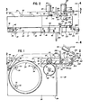
- Figure 1 is a simplified, fragmentary, front elevation view of the apparatus of the present invention with some portions of the strap and apparatus broken away to better illustrate underlying detail;
- Figure 2 is a fragmentary, plan view taken in partial cross-section generally along the plane 2-2 in Figure 1;
- Figure 3 is a simplified, cross-sectional view of the apparatus taken generally along the plane 3-3 in Figure 2;
- Figure 4 is a simplified, fragmentary,-end view taken generally along the plane 4-4 in Figure 2;
- Figure 5 is a greatly enlarged, fragmentary, cross-sectional view of the traction wheel and back-up wheel assembly taken generally along plane 5-5 in Figure 2;
- Figure 6 is a fragmentary, cross-sectional view taken generally along the plane 6-6 in Figure 5;
- Figure 7 is a view similar to Figure 5, but showing the back-up wheel in a moved position disengaged from the traction wheel;
- Figure 8 is a fragmentary, cross-sectional view taken generally along the plane 8-8 in Figure 7;
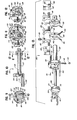
- Figure 9 is a greatly enlarged, partial, cross-sectional view of the gripping member assembly;
- Figure 10 is a fragmentary, cross-sectional view taken generally along the plane 10-10 in Figure 9;
- Figure 11 is a greatly enlarged, fragmentary, partial cross-sectional view taken along the plane 11-11 in Figure 10;
- Figure 12 is agreatly enlarged, fragmentary, partial cross-sectional view taken generally along the plane 12-12 in Figure 10;
- Figure 13 is an enlarged, fragmentary, exploded, perspective view of the gripping member assembly illustrated in Figures 9-12;
- Figures 14A, 14B, 14C, 14D, 14E, 14F, 14G, 14H, and 14I are simplified, fragmentary, front elevation views illustrating the operational sequence of the illustrated preferred embodiment of the apparatus of the present invention according to one form of the method of the present invention; and
- Figures 14A', 14B', 14C', and 14D' are rear elevation views of the gripping member assembly of the apparatus shown in an operating sequence - corresponding with the sequence of operation illustrated in Figures 14A, 14B, 14C, and 14D, respectively.
- While this invention is susceptible of embodiment in many different forms, this specification and the accompanying drawings disclose only one specific form as an example of the use of the invention. The invention is not intended to be limited to the embodiments so described, and the scope of the invention will be pointed out in the appended claims.
- For ease of description, the disclosed novel apparatus is described in the normal (upright) operating position, and terms such as upper, lower, horizontal, etc., are used with reference to this position. It will be understood, however, that the novel apparatus may be manufactured, stored, transported, used, and sold in an orientation other than the exact orientation described.
- The apparatus of this invention is used with, or includes, certain conventional components and control mechanisms, the details of which, although not fully illustrated or described, will be apparent to those having skill in the art and an understanding of the necessary functions of such components and control mechanisms.
- Some of the figures illustrating the apparatus show conventional structural details and mechanical elements that will be recognized by one skilled in the art. However, the detailed descriptions of such conventional elements are not necessary to an understanding of the invention, and accordingly, are not herein presented.
- Referring now to Figure 1, the novel strap loop-forming apparatus of the present invention is designated generally by
reference numeral 20. Theapparatus 20 includes aframe 28 defining a generally planarbase contact surface 29 for being placed on a suitable support surface S (Figure 14E), such as a table top. - Although the
apparatus 20 may be used to form a loop in a variety of binding or strapping materials, it is especially suitable for forming a loop from non-metallic, thin film strap, such as strap having a thickness of less than about 0.13 mm. (0.005 in.). Such strap is designated generally in the figures byreference numeral 22.Such strap 22 may be fabricated from polypropylene, polyester, nylon, or other suitable materials. - A presently preferred form of
such strap 22 is polypropylene strap having a thickness of 0.08 mm. (0.003 in.) and a width of 19.05 mm. (0.75 in.). Such film is extremely flexible. It cannot be easily pushed through a conventional strap chute. It does not, by itself, maintain an open, circular loop of significant size when the loop hangs downwardly under the influence of gravity. Novel methods and means are required for forming a useful loop of such strap for conventional low tension binding applications. - With continued reference to Figure 1, it is seen that the
strap 22 is preferably provided on astrap reel 24 which may be mounted onsuitable support studs 26 projecting from the front of theapparatus frame 28. Suitable retaining members, such aswashers 30, are disposed on eachstud 26 for retaining thereel 24 in proper position. Thestuds 26 and thewashers 30 may be removed when desired to accommodate removal of thestrap reel 24 and replacement with a new reel. - In the simplest form contemplated by the present invention, the
strap reel 24 may be freely rotatable on thestuds 26 about the central axis of thereel 24. However, if desired, conventional or special snubbing and/or retracting mechanisms may be incorporated. For example, afriction snubbing device 32 may be provided as illustrated in Figures 1 and 2. Thedevice 32 includes anarm 34 pivotally mounted about apin 36 to theframe 28. The distal end of thearm 34 carries aroller 38 rotatably mounted about apin 40 that is disposed on thearm 34. Thearm 34 is biased against the outer layer ofstrap 22 on thereel 24 by aspring 42 which is carried on a mountingblock 44 on theframe 28. - When the
strap 22 is withdrawn (pulled forwardly) off the reel (clockwise as viewed in Figure 1) by means described in detail hereinafter, theroller 38 acts as a snubber or friction brake to prevent over-rotation of thereel 24 when the pulling force on thestrap 22 is terminated. - Additionally, or alternatively, the
reel 24 could include a conventional or special strap retracting means (not illustrated). Such a retracting means would function in the well-known amd conventional manner to apply counter-torque or retracting torque to thereel 24 so as to oppose the strap withdrawing torque. The retracting torque would be relatively low and could be easily overcome by the strap withdrawing torque. However, when the strap withdrawing torque falls below a predetermined magnitude, the retracting means would cause thereel 24 to rotate (in the counterclockwise direction as viewed in Figure 1) to rewind thestrap 22. The detailed design and specific structure of such a conventional or special retracting means form no part of the present invention. - As best illustrated in Figures 1 and 5-8, the
apparatus 20 includes atraction wheel 50. Preferably thetraction wheel 50 has a moldedpolyurethane periphery 52 which may be grooved. In some applications, an O-ring of conventional manufacture may be employed in place of the molded polyurethane periphery. Other compositions and structures may be provided for thetraction wheel 50, depending upon, inter alia, the type of strap, the strap width and thickness, the surface speed of the wheel, and the operating force of thestrap 22 against the wheel. - The
traction wheel 50 is mounted on ahub 54 by means of a key 56, and thehub 54 is mounted on ashaft 58 which is journaled for rotation in a mounting block 60 (Figures 6 and 7). A motor 62 (Figures 2 and 4) is operably connected with theshaft 58 for rotating thetraction wheel 50 in either direction. Themotor 62 is appropriately mounted to a suitable frame portion which is only diagrammatically illustrated in Figures 2 and 4 by the slanted lines 64. - A back-up
wheel 66 is mounted above thetraction wheel 50 for rotation on ashaft 68 which is eccentrically mounted to the end of an enlargedcylindrical portion 70 of ashaft 72. As best illustrated in Figure 3, theshaft 72 is journaled in the mountingblock 60 and is connected on its distal end at the rear of theapparatus 20 to arod 74 which is in turn connected to anactuator rod 76 of anelectric solenoid actuator 78 which is mounted with abracket 80 to a portion of theframe 28. - With reference to Figures 5 and 6, it can be seen that the
axis 82 of the back-upwheel shaft 68 is laterally offset with respect to theaxis 84 of theenlarged end portion 70 of theshaft 72. The back-upwheel 66 is thus eccentrically movable between a first position (illustrated in Figures 5 and 6) wherein the back-upwheel 66 engages thetraction wheel 50 and a second position (illustrated in Figures 7 and 8) wherein the back-upwheel 66 is spaced away from thetraction wheel 50. - The movement of the back-up
wheel 66 is effected by actuation of the solenoid actuator 78 (Figures 2 and 3). Theactuator 78 may have an internal spring (not illustrated) for normally maintaining theactuator rod 76 in the fully retracted position so as to normally bias the back-upwheel 66 against thetraction wheel 50. Energization of theactuator 78 extends the rod 76 (in the direction ofarrow 85 in Figure 3) to raise the back-upwheel 66 away from thetraction wheel 50. - When the back-up
wheel 66 is moved toward engagement with thetraction wheel 50 as illustrated -in Figure 5, the strap (not illustrated in Figures 5-8) would be urged by the back-upwheel 66 against the traction wheel 50 (with a small force). On the other hand, when the back-upwheel 66 is moved away from the traction wheel 50 (as illustrated in Figures 7 and 8), the strap would not be sufficiently frictionally engaged with the surface of thetraction wheel 50 to effect movement of the strap when the traction wheel is rotating. - Since the
traction wheel 50 may be operated in either direction of rotation, thetraction wheel 50 can function as a feeding means for feeding the strap forwardly (to the right as viewed in Figure 1) and subsequently as a strap retracting or tensioning means for retracting the strap rearwardly (to the left as viewed in Figure 1). Thetraction wheel motor 62 may be a conventional electric motor and may be controlled through a conventional control system for rotation as necessary in either direction. However, it is to be realized that thetraction wheel 50 need not be rotated by a separate, dedicated motor, such asmotor 62. If desired, thetraction wheel 50 could be rotated through a suitable drive system from a prime mover (not illustrated) that could also function to operate other subassemblies in the apparatus 20 (either simultaneously and/or sequentially). - As illustrated generally in Figures 1 and 14A, the
strap 22 is withdrawn from thestrap reel 24 and extends over thetraction wheel 50 to a grippingmember assembly 100. As best illustrated in Figures 5 and 6, achannel 45 is provided for receiving thestrap 22 adjacent thetraction wheel 50, and thechannel 45 is defined on the top byguide blocks 46 and on the bottom by guide blocks 47. Thestrap 22 is guided on its inner lateral edge on the inside of theapparatus 20 by the block 60 (Figures 6 and 7). The outer lateral edge of thestrap 22 is guided on the outside of theapparatus 20 by a transparent plate 48 (visible in Figure 1, but omitted from Figures 5-8). - The gripping
member assembly 100 is provided for gripping a segment of thestrap 22 and moving the strap segment in a closed path to form a primary loop which is subsequently expanded to a larger size. The grippingassembly 100 is illustrated in detail in the exploded perspective view of Figure 13 and in the cross-sectional views of Figures of 9-12. - With reference to Figures 10 and 13, it is seen that two gripping members are provided, a
gripper arm 101 and ananvil 102. Thegripper arm 101 is mounted withscrews 103 to a generally _cylindrical portion 104 on afirst shaft 105 that is mounted for rotation relative to the apparatus frame. Theanvil 102 extends from a generallycylindrical portion 106 that is disposed at the end of a hollow,second shaft 107. The hollow,second shaft 107 is mounted concentrically on thefirst shaft 105 for rotation relative to thefirst shaft 105. As best illustrated in Figure 4, the exterior of thesecond shaft 107 is journaled for rotation in dependingflanges 108 of a portion of theframe 28. - With reference to Figures 9 and 13, it is seen that the generally
cylindrical portion 104 on the end of thefirst shaft 105 defines tworecesses 110, and eachrecess 110 receives an end of acompression spring 112. Thecylindrical portion 104, along with thesprings 112, is received within acavity 114 of the generallycylindrical portion 106 on the end of thesecond shaft 107. The outer end of eachspring 112 is received within abore 116 of the generallycylindrical portion 106. Theupper spring 112 is retained in position in the generallycylindrical portion 106 by aroll pin 118, and thelower spring 112 is retained in position in the generallycylindrical portion 106 by ascrew 120 engaged with theportion 106. - With reference to figures 9, 10, and 13, it can be seen that if the
inner shaft 105 is prevented from rotating, thesprings 112 would function to rotate the generally cylindrical portion 106 (clockwise as viewed in Figure 9) so as to move theanvil 102 toward thegripper arm 101. A mechanism for permitting such action is next described. - The rearward end of the second,
hollow shaft 107 is shorter than thefirst shaft 105, and thefirst shaft 105 extends rearwardly beyond thesecond shaft 107. A first annular member 124 (Figures 10-13) is mounted on the end of thefirst shaft 105 and is secured to a shaft 126 (Figures 2 and 4) of a suitable rotating drive means which may be in the form of amotor 128. Themotor 128 is mounted to a suitable portion of theframe 28, and such a suitable mounting portion is only diagrammatically illustrated by slantedlines 130 in Figures 2 and 4. - Although not illustrated, it may be preferable to eliminate the
motor 128 and rotate the grippingmember shaft 126 through appropriate conventional gear, chain, or belt drive elements from thetraction wheel motor 62. Alternatively, theshaft 126 may be rotated directly by a separate electric solenoid operator or by other suitable means. - The first generally
annular member 124 is secured withsuitable set screws 132 to thefirst shaft 105. The firstannular member 124 includes a cylindrical surface defining first detent element with anotch 134, the purpose of which will be described in detail hereinafter. - A second generally annular
member 138 is mounted withset screws 140 to the hollow,second shaft 107. The secondannular member 138 includes a cylindrical surface that defines a second detent element with anotch 142 and a third detent element with anotch 143. - As best illustrated in Figures 11-13, the
apparatus 20 also includes afirst pawl 151, asecond pawl 152, and athird pawl 153. Each pawl is pivotally mounted to theframe 28. With reference to Figures 11 and 12, thefirst pawl 151 and thethird pawl 153 are seen to be pivotally mounted about acommon pin 154. Thesecond pawl 152 is pivotally mounted about apin 155. - The
apparatus 20 also includes a first- biasing means orspring 161, a second biasing means orspring 162, and a third biasing means orspring 163 to effect engagement of thefirst pawl 151, thesecond pawl 152, and thethird pawl 153, respectively, with the firstdetent element notch 134, the seconddetent element notch 142, and the thirddetent element notch 143, respectively. Thefirst spring 161 is received in afirst bore 165 in ablock 166 mounted to theframe 28. Thethird spring 163 is similarly received in anadjacent bore 167 in theblock 166. Thespring 162 is received in abore 168 in ablock 169 which is also mounted to theframe 28. - With reference to Figures 11 and 13, it can be seen that a
member 170 is provided for pivoting thesecond pawl 152 out of thedetent element notch 142 against thecompression spring 162 and toward theblock 169. Themember 170 is carried on an arm 172 (Figures 11 and 3) which is pivotally mounted on a pin 174 (Figure 3) to theframe 28. The other end of thearm 172 is pivotally connected by apin 176 to anactuator arm 178 of anelectric solenoid actuator 180. Theactuator 180 is mounted with abracket 181 to theframe 28. Energization of thesolenoid actuator 180 causes thearm 178 to move downwardly (in the direction ofarrow 182 in Figure 3) to effect the pivoting action of thesecond pawl 152 out of engagement with the seconddetent element notch 142. Of course, theactuator 180 may be replaced by other suitable conventional or special means (not illustrated) for effecting the pivoting action of thesecond pawl 152. - A joint forming assembly 200 (Figures 1 and 3) is provided for cooperating with the
anvil 102 to form a joint in overlapping portions of the strap after the strap loop is formed in a manner described in detail hereinafter. The joint formingassembly 200 includes suitable strap contacting or joining member 202 (Figure 1) that is pivotally mounted about apin 204 on theframe 28. Atorsion spring 206 is disposed around thepin 204. One end of thespring 206 engages the bottom of thestrap contacting member 202, and the other end of the spring engages a fixedpin 208. Thespring 206 acts to bias thestrap contacting member 202 upwardly away from theanvil 102. - An
actuating arm 210 is mounted to one end of thestrap contacting member 202 and is adapted to be engaged by afoot 212 carried at the end of anactuator rod 214 of anelectric solenoid actuator 216. Theelectric solenoid actuator 216 is mounted to a suitable portion of the frame which is only diagrammatically illustrated in Figures 1 and 3 by the slantedlines 218. - With reference to Figure 1, it can be seen that actuation of the
electric solenoid actuator 216 to retract therod 214 in the direction ofarrow 220 will cause thestrap contacting member 202 to pivot downwardly toward theanvil 102. - The
strap contacting member 202 may employ any suitable means for joining overlapping strap portions after the strap loop is formed by means described in detail hereinafter. For example, thestrap contacting member 202 may include a vibrating mechanism for effecting a friction-fusion weld joint of the overlapping strap portions. Alternatively, thestrap contacting member 202 may contain a suitable conventional ultrasonic welding mechanism or a suitable heating mechanism for producing a joint. The formation of the joint per se, and the mechanism for forming the joint, form no part of the broadest aspects of the present invention. - Means may be provided, if desired, for automatically severing the trailing portion of the
strap 22 from the strap loop. In the preferred embodiment of the apparatus illustrated, an automatically actuated knife mechanism is provided for this purpose. Specifically, as best illustrated in Figures 1 and 4, aknife blade 230 is provided for being maintained in a normally unactuated, vertical orientation between the strap grippingmember assembly 100 and thetraction wheel 50. - The
blade 230 is pivotally connected to the apparatus frame near the bottom of theblade 230 about a suitable pivot pin (not visible in the figures). Theblade 230 is also pivotably connected at the top, by means of apin 232, to the end of anactuating rod 234 of anelectric solenoid actuator 236. As illustrated in Figure 4, theactuator 236 is pivotally mounted at its distal end by means of apin 238 to a suitable portion of the apparatus frame which is diagrammatically illustrated in Figure 4 by the slantedlines 240. - Actuation of the
actuator 236 to extend theactuator rod 234 causes theknife blade 230 to pivot downwardly to a substantially horizontal position (illustrated in cross-section in Figure 14H). In the lowered position, the leading edge of theblade 230 is sufficiently below the path of travel of the trailing portion of thestrap 22 so as to effect a severing of the strap. Preferably, a blade guard plate 250 (Figures 1 and 4) is provided on one side of theknife blade 230 and functions to block access to the knife blademovement path. - The sequence of operation of the
apparatus 20 is next described. While theapparatus 20 functions to form a primary strap loop and then expand the primary loop to a larger size in accordance with the teachings of the invention, theapparatus 20 preferably also functions to effect a complete strapping cycle wherein an article is bound with a tensioned loop of strap. This involves feeding a length of the strap from which the loop can be formed, effecting formation of the loop in a convenient orientation for accommodating the article within the loop, tensioning the loop tight about the article, joining the overlapping strap portions of the tensioned loop, and severing (before or after joint formation) the trailing portion of the strap from the tensioned loop. - A typical operating cycle of the
apparatus 20 is sequentially illustrated in Figures 14A-14I. Theapparatus 20 is ready to start a new strapping cycle when the apparatus mechanisms are in an initial or "start" position or condition as generally illustrated in Figure 14A. Figure 14A corresponds to Figure 1, but in Figure 14A thestrap 22 is shown threaded between thetraction wheel 50 and back-upwheel 66 and as having the leading end of the strap positioned on top of theanvil 102 below thegripper arm 101. - Figure 14A' illustrates the initial positions of the
annular members pawls pawls anvil 102 in either direction, andpawl 151 prevents rotation of thegripper arm 101 toward the anvil 102 (counterclockwise as viewed in Figures 9 and 14A). - The new strapping cycle is initiated by actuation of a suitable control system (not illustrated). First, the electric solenoid actuator 180 (Figure 3) is energized to pivot
link member 172 downwardly. This causes themember 170, carried by thelink member 172, to pivot thesecond pawl 152 out of engagement with the seconddetent element notch 142 as illustrated in Figure 14B. - With the
annular member 138 now unlatched, thesprings 112, which act between the gripper armfirst shaft 105 and the anvil second shaft 107 (Figures 9, 10, and 13), urge thesecond shaft 107 to rotate (counterclockwise as viewed in Figure 14B). Theanvil 102, mounted onshaft 107, rotates toward thegripper arm 101 to clamp the segment ofstrap 22. (The pawl 151 (Figure 14B') remains engaged with theannular member 124 and thereby prevents rotation of thefirst shaft 105 andgripper arm 101 relative to thesecond shaft 107 andanvil 102.) When theanvil 102 is in the "clamping" position (Figure 14B), theannular member 138 is in a moved, or incrementally rotated, position that is out of registry with theannular member 124. That is,annular member 138 has been rotated to move thenotches notch 143 is no longer in registry with thenotch 134 of the adjacent annular member 124 (Figure 14B'). - After the
anvil 102 and the connectedannular member 138 rotate to the "clamping" position as illustrated in Figures 14B and 14B', the electric solenoid actuator 180 (Figure 3) is deenergized. However, thepawl 152 remains cammed outwardly by the cylindrical surface of theannular member 138. - Next, the motor 128 (Figures 2 and 4) is energized in response to the control system to effect rotation of the gripper arm
first shaft 105 in the counterclockwise direction as viewed in Figures 14B' and 14C'. This rotation corresponds to the clockwise direction of rotation of thegripper arm 101 when viewing theapparatus 20 from the front as illustrated in Figures 14B and 14C. - Since the
anvil 102 is biased by thesprings 112 to clamp thestrap 22 against thegripper arm 101, thesecond shaft 107 andanvil 102 extending therefrom rotate in the clamping relationship with thegripper arm 101. Theannular members connected shafts annular member 138 that occurred when theanvil 102 initially clamped thestrap 22 against the gripper arm 101). - Figures 14C and 14C' show the
anvil 102 andarm 101 rotated a little more than 180° from the initial position illustrated in Figures 14A and 14A', and Figure 14C' shows how thepawls annular member 138 and how thepawl 151 is cammed outwardly by the cylindrical surface of theannular member 124. - As best illustrated in Figures 14C and 14D, rotation of the
gripper member assembly 100 causes thestrap 22 to form a loop about theanvil 102. During rotation of thegripper member assembly 100, thestrap 22 is pulled off of thestrap reel 24. Thetraction wheel 50 need not be rotated bymotor 62 as thestrap 22 is pulled off of the strap reel 24-by the rotatinggripper member assembly 100 if the back-upwheel 66 is elevated to accommodate the pulling of thestrap 22 over the top of thetraction wheel 50. However, thetraction wheel 50 is preferably also simultaneously rotated to feed the strap forward. To this end, the back-upwheel 66 is maintained in the lowered position, and thetraction wheel motor 62 is energized substantially simultaneously with the energization of thegripper assembly motor 128. - Further, the
traction wheel motor 62 is preferably operated to rotate thetraction wheel 50 at a speed sufficient to feed thestrap 22 at a rate greater than that required to accommodate the rotation of thegripper assembly 100. Specifically, it is desired to provide enough strap around theanvil 102 so that the initial, primary loop formed about theanvil 102 is somewhat larger than theanvil 102. This prevents thestrap 22 from being tightly wrapped around theanvil 102. Tightly wrapping the loop ofstrap 22 around theanvil 102 could, with some types of straps (e.g., thin film strap), cause excessive forces to be imposed on the strap and/or cause the strap to crease. - After the
gripper member assembly 100 has been rotated to the position illustrated in Figure 14D, theannular member 138 is again in its initial orientation wherein thedetent notch 142 is aligned to receive thepawl 152 which is biased into engagement with thenotch 142 by thespring 162. Since the electric solenoid actuator 180 (Figure 3) has been previously deenergized, themember 170 andlink arm 172 connected to theactuator 180 afford no substantial resistance to the return of thepawl 152 to its original latching position as illustrated in Figure 14D'. - At this point, the
gripper assembly motor 128 is deenergized and its rotation terminated by a suitable electric brake (not illustrated) or other suitable means. Although thethird pawl 153 is also biased back into engagement with thenotch 143 on the annular member 138 (Figure 11) by thespring 163, thefirst pawl 151 remains cammed outwardly against the outer cylindrical surface of theannular member 124. Theannular member 124 is still maintained out of registry relative to theannular member 138 by means of the clamping springs 112 (Figures 13 and 14B). - Although the rotation of the
gripper assembly motor 128 is terminated at this point, thetraction motor 62 continues to rotate thetraction wheel 50 to feed thestrap 22 forward so as to expand the primary loop to an expanded loop having a larger size for accommodating an article A as illustrated in Figure 14E. Preferably, as best illustrated in Figure 14E, theapparatus 20 has been positioned with the generally planarbase contact surface 29 on a support surface S (such as the top of a table or the like). Thegripper member assembly 100 is thus cantilevered over the support surface S, and the expanding loop ofstrap 22 is free to grow downwardly. - If desired, the
gripper member assembly 100 could be located near the bottom of theapparatus 20 in a non-cantilevered orientation with the "at rest" initial position of thegripper member assembly 100 being oriented 180 degrees from the position illustrated in Figure 1. This would permit the loop ofstrap 22 to expand upwardly. - In any case, before the article A is placed within the loop, the loop is allowed to grow to the desired size. Typically, in the illustrated embodiment of the
apparatus 20, the bottom of the loop would contact the support surface S, and this would cause the sides of the strap loop to bow outwardly. One side of the strap loop would eventually come to rest against the vertical side of theapparatus frame 28, and the other side of the strap loop, being unrestrained, would bow outwardly a greater amount. This results in the formation of a strap loop having a somewhat rectangular configuration which more easily accommodates an article A having a typical rectangular shape. - After the article A has been positioned within the expanded loop of
strap 22, the strap loop is tensioned about the article as best illustrated in Figure 14F. To this end, an appropriate control system is provided for terminating the feeding of thestrap 22 and for initiating retraction of thestrap 22. This may be effected by means of conventional timer systems or traction wheel rotation counting systems well-known to those skilled in the art. - In any event, when the desired amount of
strap 22 has been fed to expand the loop to the desired size, the traction wheel motor rotation is reversed so as to reverse the direction of rotation f the traction wheel 50 (in the direction ofarrow 260 illustrated in Figure 14F). Thestrap 22 is thus drawn tight about the article A. As thestrap 22 is retracted, appropriate mechanisms associated with thestrap wheel 24 may effect rotation of thestrap reel 24 to take up the retracting strap. Such mechanisms, previously discussed above, may include conventional torque devices for effecting the take-up rotation of thereel 24 whenever the withdrawing tension on thestrap 22 is less than some predetermined value. - In any event, when the
strap 22 has been drawn tight around the article A, the rotation of thetraction wheel 50 in the tensioning direction (counterclockwise as in Figure 14F) is terminated by any suitable conventional or special means. One suitable conventional means could include a strap tension sensing system of conventional design (not illustrated). Alternatively, thetraction wheel motor 62 could be designed in the well-known manner to stall at the desired tension level. - The strap tension is maintained by preventing rotation of the
traction wheel 50 back in the clockwise direction (as viewed in Figure 14F). To this end, thetraction wheel motor 62 may be maintained in the stall condition or themotor 62 may be deenergized and an electric or mechanical brake may be applied. - In any event, with tension maintained on the strap loop about the article A, the overlapping strap ends on top of the
anvil 102 are joined by any suitable conventional or special process. To this end, thestrap joining member 202 is lowered against the overlapping strap segments to press the strap segments together on top of theanvil 102. This is effected by actuating the electric solenoid actuator 216 (Figures 1 and 3) to cause thestrap joining member 202 to pivot downwardly as best illustrated in Figure 14G. - As discussed above, the
strap joining member 202 may include suitable mechanisms for joining the overlapping strap segments, such as ultrasonic mechanisms, friction fusion mechanisms, strap heating mechanisms, and the like. Such mechanisms may be of conventional design or may be of special design. The details of such mechanisms form no part of the present invention. - When the
strap joining member 202 is lowered against the overlapping strap segments, sufficient force is preferably exerted on the overlapping strap segments against theanvil 102 so as to withstand the loop tension force. The tension on the trailing portion of the strap may then be released, if desired. Typically, for light load binding applications, the force between theanvil 102 and thestrap joining member 202 would be about five pounds. - After the overlapping strap segments have been appropriately joined, the electric solenoid actuator 216 (Figures 1 and 3) is deenergized to permit the
spring 206 to return thestrap joining member 202 to the elevated position. - Before, during, or after joining the overlapping strap segments, the trailing portion of the strap may be severed from the tensioned loop. If the strap is severed before joining the overlapping strap portions, the severance should be effected only after the
strap joining member 202 has been lowered against the overlapping strap portions so as to maintain loop tension when the strap is severed. - To sever the strap, the
knife blade 230 is pivoted downwardly to sever the trailing portion of the strap from the strap loop around the article A as illustrated in Figure 14H. This is effected by energizing the electric solenoid actuator 236 (Figure 4). Theknife blade 230 may be returned to the elevated position by means of suitable biasing means (not illustrated) associated with theknife blade 230 per se or integral with theelectric solenoid actuator 236. If desired, the strap may be severed by other suitable means, including a hot wire, saw, and the like. - Preferably, the
strap 22 should be severed while the trailing portion is not subject to a retraction force or while the strap is otherwise prevented from being pulled back toward thestrap reel 24. It is desired to avoid having to subsequently feed the strap forward again to the severing point. If the retracting force on the trailing portion of thestrap 22 is to be released prior to severing, this can be done by locking thestrap reel 24 to eliminate the retracting torque and by releasing any brake on the deenergizedtraction wheel motor 62. On the other hand, if tension is still being maintained by an energized, but "stalled"traction wheel motor 62, then themotor 62 could be deenergized or the back-upwheel 66 could be raised off of thestrap 22 and away from thetraction wheel 50. The latter alternative operation is effected by actuating the electric solenoid actuator 78 (Figures 2 and 3). - As explained above in detail, energization of the
actuator 78 to extend therod 76 will pivot the connectingrod 74 to raise the back-upwheel 66 to the elevated position illustrated in Figures 7 and 8. Immediately prior to the elevation of the back-upwheel 66, thestrap reel 24 is locked by suitable conventional means (not illustrated) against rotation in the retraction direction. With the back-upwheel 66 elevated and no retraction torque being applied by thestrap reel 24, the trailing portion of thestrap 22 is no longer subjected to a retracting force. Thus, when theknife blade 230 is lowered to sever the strap, the severed trailing portion of the strap will not retract further into theapparatus 20. - After the loop strap segments are joined, and after the trailing portion of strap is severed from the loop, the gripper assembly motor 128 (Figures 2 and 4) is again energized momentarily to rotate the
first shaft 105 andgripper arm 102 carried thereon to the "open" position illustrated in Figure 141. The control system may initiate this rotation of themotor 128 after a suitable time delay in response to actuation of theknife blade actuator 236 or of strap contactingmember actuator 216. In any event, thegripper arm 101 rotates away from theanvil 102 which remains in the substantially horizontal position shown in Figure 141 owing to the latching of theannular member 138 and connected anvilsecond shaft 107 by thepawls - The rotation of the
motor 128 is terminated after thegripper arm 101 has reached the open position illustrated in Figure 141. In this position, theannular member 124, which is connected to the gripper armfirst shaft 105, has rotated to the point where thedetent notch 134 in theannular member 124 is again in the "home" position to receive thefirst pawl 151 in the engaging relationship as illustrated in Figure l4A'. - The article A can then be removed from the
apparatus 20 by moving the article A transversely along the length of theanvil 102 so that the joint portion of the tensioned loop slips off of the end of theanvil 102 and snaps into engagement with the article A. - A new length of
strap 22 may then be fed forward into thegripper assembly 100. To this end, the solenoid actuator 78 (Figures 2 and 3) is deenergized to permit the actuator internal spring mechanism (not illustrated) to effect a lowering of the back-upwheel 66 into engagement with thestrap 22 on thetraction wheel 50. Theelectric motor 62 is simultaneously energized to rotate thetraction wheel 50 so as to feed thestrap 22 forward a small amount to position the strap end portion over theanvil 102 as illustrated in Figure 14A prior to initiating the next strapping cycle. - It will be readily observed from the foregoing detailed description of the invention and from the illustrated embodiment thereof that numerous variations and modifications may be effected without departing from the true spirit and scope of the novel concepts or principles of the invention.
Claims (10)
said method characterized in that:
Applications Claiming Priority (2)
| Application Number | Priority Date | Filing Date | Title |
|---|---|---|---|
| US801605 | 1985-11-25 | ||
| US06/801,605 US4683017A (en) | 1985-11-25 | 1985-11-25 | Method and apparatus for forming a loop with end-gripped strap |
Publications (2)
| Publication Number | Publication Date |
|---|---|
| EP0225540A1 true EP0225540A1 (en) | 1987-06-16 |
| EP0225540B1 EP0225540B1 (en) | 1989-10-04 |
Family
ID=25181572
Family Applications (1)
| Application Number | Title | Priority Date | Filing Date |
|---|---|---|---|
| EP86116338A Expired EP0225540B1 (en) | 1985-11-25 | 1986-11-24 | Method and apparatus for forming a loop with end-gripped strap |
Country Status (5)
| Country | Link |
|---|---|
| US (1) | US4683017A (en) |
| EP (1) | EP0225540B1 (en) |
| JP (1) | JPS62235008A (en) |
| CA (1) | CA1278996C (en) |
| DE (1) | DE3666024D1 (en) |
Families Citing this family (16)
| Publication number | Priority date | Publication date | Assignee | Title |
|---|---|---|---|---|
| US5462631A (en) * | 1986-07-24 | 1995-10-31 | Gardner; John P. | Tape winding apparatus |
| US4878985A (en) * | 1987-03-20 | 1989-11-07 | Xerox Corporation | Apparatus for preparing belts |
| US4838964A (en) * | 1987-03-20 | 1989-06-13 | Xerox Corporation | Process for preparing belts |
| JPS63258713A (en) * | 1987-04-17 | 1988-10-26 | ストラパック株式会社 | Band supply and stretching device in packaging machine |
| US4968369A (en) * | 1988-10-03 | 1990-11-06 | Xerox Corporation | Belt fabrication machine |
| US5024149A (en) * | 1989-04-15 | 1991-06-18 | Signode Corporation | Binding strap operating apparatus |
| US4957584A (en) * | 1989-05-18 | 1990-09-18 | Eastman Kodak Company | Apparatus for forming endless loops from sheet material |
| IT1255976B (en) * | 1992-11-30 | 1995-11-17 | APPARATUS TO APPLY ADHESIVE HANDLES TO COLLARS | |
| US5640899A (en) * | 1995-12-15 | 1997-06-24 | Illinois Tool Works Inc. | Strap severing and ejecting apparatus and method for strapping machine |
| DE19730449A1 (en) * | 1997-07-16 | 1999-01-21 | Mosca G Maschf | Clamping device for strapping machines |
| DE19828244A1 (en) * | 1997-07-22 | 1999-01-28 | Smb Schwede Maschinenbau Gmbh | Drive mechanism for banding machine |
| GB2332164A (en) * | 1997-12-13 | 1999-06-16 | Harrison Saw & Tool Ltd | Continuous band manufacture |
| AU2747500A (en) | 1999-01-29 | 2000-08-18 | Bradley P. Actis | Automatic bale strapping system |
| US6487833B1 (en) | 2000-01-29 | 2002-12-03 | Howard W. Jaenson | Strap welding system and method |
| EP2960164B1 (en) * | 2013-02-22 | 2018-06-06 | Hangzhou Youngsun Intelligent Equipment Co., Ltd. | Machine core of packing machine |
| US11021282B2 (en) * | 2017-07-19 | 2021-06-01 | Signode Industrial Group Llc | Strapping device configured to carry out a strap-attachment check cycle |
Citations (2)
| Publication number | Priority date | Publication date | Assignee | Title |
|---|---|---|---|---|
| US4077313A (en) * | 1976-12-20 | 1978-03-07 | Signode Corporation | Method of tensioning and joining a formed strap loop about a package |
| US4079667A (en) * | 1976-12-20 | 1978-03-21 | Signode Corporation | Method of forming and tensioning a strap loop about a package |
Family Cites Families (9)
| Publication number | Priority date | Publication date | Assignee | Title |
|---|---|---|---|---|
| US31353A (en) * | 1861-02-05 | Folding table | ||
| GB936718A (en) * | ||||
| GB1321219A (en) * | 1971-04-21 | 1973-06-27 | Hoesch Ag | Method and apparatus for automatically strapping packages |
| US3749622A (en) * | 1971-11-08 | 1973-07-31 | Ikegai Iron Works Ltd | Method of welding thermoplastic band for use in packing machine as well as apparatus relevant thereto |
| JPS528095B2 (en) * | 1972-04-24 | 1977-03-07 | ||
| DE2403261C3 (en) * | 1974-01-24 | 1978-07-20 | Maryan 5443 Kaisersesch Stankovicc-Gansen | Device for automatic strapping |
| US4378262A (en) * | 1981-02-04 | 1983-03-29 | Signode Corporation | Method and apparatus for forming and tensioning a strap loop about a package |
| US4482421A (en) * | 1982-06-02 | 1984-11-13 | Signode Corporation | Ultrasonic friction-fusion method and apparatus |
| JPS59163113A (en) * | 1983-03-07 | 1984-09-14 | 畑谷 寛 | Bundling device by tape |
-
1985
- 1985-11-25 US US06/801,605 patent/US4683017A/en not_active Expired - Lifetime
-
1986
- 1986-11-17 CA CA000523075A patent/CA1278996C/en not_active Expired - Lifetime
- 1986-11-24 DE DE8686116338T patent/DE3666024D1/en not_active Expired
- 1986-11-24 EP EP86116338A patent/EP0225540B1/en not_active Expired
- 1986-11-25 JP JP61281624A patent/JPS62235008A/en active Pending
Patent Citations (2)
| Publication number | Priority date | Publication date | Assignee | Title |
|---|---|---|---|---|
| US4077313A (en) * | 1976-12-20 | 1978-03-07 | Signode Corporation | Method of tensioning and joining a formed strap loop about a package |
| US4079667A (en) * | 1976-12-20 | 1978-03-21 | Signode Corporation | Method of forming and tensioning a strap loop about a package |
Also Published As
| Publication number | Publication date |
|---|---|
| US4683017A (en) | 1987-07-28 |
| CA1278996C (en) | 1991-01-15 |
| EP0225540B1 (en) | 1989-10-04 |
| JPS62235008A (en) | 1987-10-15 |
| DE3666024D1 (en) | 1989-11-09 |
Similar Documents
| Publication | Publication Date | Title |
|---|---|---|
| EP0225540B1 (en) | Method and apparatus for forming a loop with end-gripped strap | |
| JP3540403B2 (en) | Method and apparatus for power tying machine | |
| US4378262A (en) | Method and apparatus for forming and tensioning a strap loop about a package | |
| JPH0629065B2 (en) | Binding device | |
| US4605456A (en) | Method and apparatus for feeding and tensioning strap in a strapping machine | |
| JP2543483B2 (en) | Strap cutting and releasing mechanism of the binding machine | |
| JP4663907B2 (en) | Winding machine and binding device | |
| US4011807A (en) | Strap feeding and tensioning machine | |
| EP0120948B1 (en) | Tying machine and method | |
| NZ240171A (en) | Method and apparatus for controlling tension in a strap loop when | |
| EP0688264A1 (en) | Adhesive applicator | |
| JPH08508703A (en) | Manual tape feeder | |
| US4001064A (en) | Manual strapping tool | |
| JPH021726B2 (en) | ||
| JP4064472B2 (en) | Improvement of ultrasonic bundling tools | |
| CN100366508C (en) | Strapping machine with automatic strap clearing and reloading device | |
| JP2001500454A (en) | Device for winding items with tape | |
| JPS6234606B2 (en) | ||
| CA1167366A (en) | Method and apparatus for forming and tensioning a strap loop about a package | |
| JPS621045Y2 (en) | ||
| JP3513386B2 (en) | Binding machine | |
| US5471918A (en) | No-load-run strap release control mechanism for a strapping machine | |
| JP2567168B2 (en) | A tape sticking device for packaging items in a packaging machine | |
| JP3547609B2 (en) | Bonding device in binding machine | |
| JP2582503Y2 (en) | Coin wrapping machine |
Legal Events
| Date | Code | Title | Description |
|---|---|---|---|
| PUAI | Public reference made under article 153(3) epc to a published international application that has entered the european phase |
Free format text: ORIGINAL CODE: 0009012 |
|
| AK | Designated contracting states |
Kind code of ref document: A1 Designated state(s): DE FR GB IT |
|
| 17P | Request for examination filed |
Effective date: 19871215 |
|
| 17Q | First examination report despatched |
Effective date: 19890201 |
|
| ITF | It: translation for a ep patent filed |
Owner name: GUZZI E RAVIZZA S.R.L. |
|
| GRAA | (expected) grant |
Free format text: ORIGINAL CODE: 0009210 |
|
| RAP1 | Party data changed (applicant data changed or rights of an application transferred) |
Owner name: SIGNODE CORPORATION |
|
| AK | Designated contracting states |
Kind code of ref document: B1 Designated state(s): DE FR GB IT |
|
| REF | Corresponds to: |
Ref document number: 3666024 Country of ref document: DE Date of ref document: 19891109 |
|
| ET | Fr: translation filed | ||
| PLBE | No opposition filed within time limit |
Free format text: ORIGINAL CODE: 0009261 |
|
| STAA | Information on the status of an ep patent application or granted ep patent |
Free format text: STATUS: NO OPPOSITION FILED WITHIN TIME LIMIT |
|
| 26N | No opposition filed | ||
| ITTA | It: last paid annual fee | ||
| PGFP | Annual fee paid to national office [announced via postgrant information from national office to epo] |
Ref country code: FR Payment date: 19931011 Year of fee payment: 8 |
|
| PGFP | Annual fee paid to national office [announced via postgrant information from national office to epo] |
Ref country code: DE Payment date: 19931022 Year of fee payment: 8 |
|
| PGFP | Annual fee paid to national office [announced via postgrant information from national office to epo] |
Ref country code: GB Payment date: 19931028 Year of fee payment: 8 |
|
| PG25 | Lapsed in a contracting state [announced via postgrant information from national office to epo] |
Ref country code: GB Effective date: 19941124 |
|
| GBPC | Gb: european patent ceased through non-payment of renewal fee |
Effective date: 19941124 |
|
| PG25 | Lapsed in a contracting state [announced via postgrant information from national office to epo] |
Ref country code: FR Effective date: 19950731 |
|
| PG25 | Lapsed in a contracting state [announced via postgrant information from national office to epo] |
Ref country code: DE Effective date: 19950801 |
|
| REG | Reference to a national code |
Ref country code: FR Ref legal event code: ST |
|
| PG25 | Lapsed in a contracting state [announced via postgrant information from national office to epo] |
Ref country code: IT Free format text: LAPSE BECAUSE OF NON-PAYMENT OF DUE FEES;WARNING: LAPSES OF ITALIAN PATENTS WITH EFFECTIVE DATE BEFORE 2007 MAY HAVE OCCURRED AT ANY TIME BEFORE 2007. THE CORRECT EFFECTIVE DATE MAY BE DIFFERENT FROM THE ONE RECORDED. Effective date: 20051124 |