EP0225607A2 - Portable radio telephone system - Google Patents
Portable radio telephone system Download PDFInfo
- Publication number
- EP0225607A2 EP0225607A2 EP86116857A EP86116857A EP0225607A2 EP 0225607 A2 EP0225607 A2 EP 0225607A2 EP 86116857 A EP86116857 A EP 86116857A EP 86116857 A EP86116857 A EP 86116857A EP 0225607 A2 EP0225607 A2 EP 0225607A2
- Authority
- EP
- European Patent Office
- Prior art keywords
- telephone system
- radio
- radio telephone
- portable
- frequency channels
- Prior art date
- Legal status (The legal status is an assumption and is not a legal conclusion. Google has not performed a legal analysis and makes no representation as to the accuracy of the status listed.)
- Granted
Links
Images


Classifications
-
- H—ELECTRICITY
- H04—ELECTRIC COMMUNICATION TECHNIQUE
- H04W—WIRELESS COMMUNICATION NETWORKS
- H04W16/00—Network planning, e.g. coverage or traffic planning tools; Network deployment, e.g. resource partitioning or cells structures
- H04W16/14—Spectrum sharing arrangements between different networks
-
- H—ELECTRICITY
- H04—ELECTRIC COMMUNICATION TECHNIQUE
- H04W—WIRELESS COMMUNICATION NETWORKS
- H04W16/00—Network planning, e.g. coverage or traffic planning tools; Network deployment, e.g. resource partitioning or cells structures
- H04W16/02—Resource partitioning among network components, e.g. reuse partitioning
- H04W16/12—Fixed resource partitioning
Definitions
- This invention relates generally to a portable radio telephone system. More particularly, the present invention relates to a private radio telephone system, for use in a local area such as in a office building or in a factory, of the type wherein when its portable telephone set is taken out from the area, it can communicate with subscribers of public telephone network through a public cellular radio telephone system which has already been in service over urban areas.
- a public cellular radio telephone system has been known in the past as a urban cellular radio telephone system.
- its portable telephone set When its portable telephone set is brought into an office building or in a factory and connected to a subscriber of the private branch exchange for communication, not only the quality of telephone voice drops due to radio wave propagation attenuation by the office building but also the telephone charge of the urban cellular telephone system must be payed.
- the portable telephone set becomes expensive because it must have a radio frequency circuit of the private radio frequency channels in addion to the -radio frequency of the urban cellular radio telephone.
- the object of the present.invention is to accomplish a portable radio telephone system wherein a portable telephone set can be used both for an urban public cellular radio telephone system and for a private rad telephone system which is build inside a local area.
- the present invention is directed to accomplish a portable radio telephone system wherein direct access can be made from a portable telephone set to the radio frequency circuit of a private branch exchange without causing any radio wave interference to a heretofore known urban cellular radio telephone system
- a portable radio telephone system of the type wherein a given area is divided into a plularity of large areas, each of the large areas is further divided into a plularity of small cellular areas, wherein the reuse of the same frequency channel is permitted between the large areas, different frequency channels are allocated to the small cellular areas of each large area and public radio communicationis made by portable telephone sets by use of the radio waves of the frequency channels allocated to the small cellular areas, the object of the present invention described above can be accomplished by a private radio telephone system consisting of an antenna for transmitting and receiving a radio wave pair which doubly reuse the same frequency channel pair with the public cellular radio telephone system but do not use the frequency channels allocated to the small cellular area wherein the private telephone system exists, a private branch exchange and a transceiver both of which are connected to the antenna and private radio communication is made through private.branch exchange by use of the portable telephone sets.
- the power intensity of the radio wave radiated from the antenna is kept to a very low intensity level so that it does not affect the public cellular radio telephone system in the large areas, and also the frequency channel pair is selected so that they hardly interfere the public cellular radio telephone system of the large areas.
- the antenna described above may have directivity.
- the portable radio telephone system of the present invention When the portable radio telephone system of the present invention is disposed in a district where the density of subscribers of a public cellular radio telephone system is high, the radious of the small cellular area( cell or sector ) becomes little so that the service area of a local private system using a single antenna becomes narrow.
- the local area is divided into a plularity of mini cells with each antenna and radio waves of different frequency channel pairs are reused among the mini cells to secure a required service area, as described, for example, in "Personal Communication", September, 1985, pp. 28.
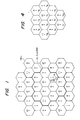
- Fig. 1 shows an example of cell disposition of a heretofore known public cellular radio telephone system in order to have the present invention more easily understood.
- a given are is divided into a plurality of large areas (which are referred to as "cluster” ) represented by thick line and each of the clusters is divided into twelve cells ( small areas ) 1 - 12.
- An antenna for transmission and reception ( represented by black dot “.” ) is disposed at the center of each cell.
- Radio frequency channels are allocated to each cell in the number corresponding to the traffic of the radio telephone. These radio waves will be called “f” in the cell 1, “f 2 " in the cell 2, “f 3 " in the cell 3, and so forth.
- the f 1 , f 2 , ....radio waves have an allocated bandwidth, and a plurality of frequency channels exist in each bandwidth related to the radio telephone traffic. Additionally, the position of the cell 1 in the cluster 13 is selected so that the intensity of the f wave interference from outside the cluster becomes minimal.
- radio communication is made between a private branch radio telephone system in one cell and a portable telephone set by use of frequencies different from the frequencies allocated to the cell.
- the frequency and intensity of the radio waves used for the private branch radio telephone system are selected in the following manner lest radio wave interference occurs with the other cells in the cluster.
- the frequency channels allocated to the cell 1 must be the channels which are used in the most apart from the cell 1.
- the f 2 wave of the cell 2 exists'for the cell 1.
- the cell 4 is the most remote from the cell 1 inside the cluster 13, but the interference intensity of the f 4 wave from outside the cluster 13 is greater than that of the f 2 wave.
- the f 3 wave used in the cell 3 also satisfies the condition described above.
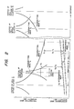
- Fig. 2 shows the intensity of radio wave used by the portable radio telephone system of the present invention.
- the electric field intensity E 1 of the radio wave radiated from the cell 1 can be expressed by the following equation if the irregular radio wave propagation does not exist: where R is the distance from a transmitting antenna to a reception antenna, a is a proportional coefficient and P 1 is the transmitting power of the antenna.
- the radious of the cell are determined at a boundary where the ratio S 1 /I 1 of the intensity S 1 of the received f l wave to the intensity I 1 of the f 1 wave interference from outside the cluster 13, so that the the quality of telephone voice is kept a predetermined level.
- the transmitting power P 2 of the private radio telephone system 0 of the present invention is kept to a value so that the ratio of the intensity S 2 of the transmitting f 2 wave to the intensity I 2 of the f 2 wave interference at the boundary of the local service area satisfies the conditions below:
- Fig. 3 is a structural view of the portable radio telephone system in accordance with one embodiment of the present invention.
- a private branch exchange (PBX ) 15 for wired telephone subscribers is disposed in the private radio telephone system 0 ( corresponding to 0 in Fig. 1 ) and radio telephone subscriber circuit are added thereto.
- the radio telephone subscriber circuits are connected to transmission/reception antennas 18, 19 through transceivers ( TRX ) 16 and a booster 17, and the f2 wave having the intensity that can supress the f 2 wave interference of the public cellular radio telephone system, is transmitted from the antennas and enables the portable telephone set 20 to communicate by receiving the f 2 wave from the antennas.
- TRX transceivers
- the portable telephone set 20 can communicate with the f l wave from the cell 1 of the public cellular radio telephone system.
- the transmitting power of the portable telephone set 20 is also determined to a value that satisfies the condition of eq. (2).
- This controlling is made automatically by a radio frequency controller disposed inside the the private branch exchange (PBX) 15.
- PBX private branch exchange
- the method controlling the transmission power for the private radio telephone system is the same as the method used for the heretofore known public cellular radio telephone system.
- the cells 4, 2, 5 in Fig. 1 use the f 5 , f 3 and f 6 waves, respectively.
- the total interference intensity must be determined below a predetermined level.
- the condition which prevents the interference to the nearest adjacent system of the present invention is far severer.
- the interference is restricted by providing the antenna with directivity.
- the service area of the private radio telephone system of the present invention becomes extremely narrow in order to prevent their mutual interference.
- other radio frequency channels e. g. alternate use of f 2 and f 3 waves in the cell 1 .
- Fig. 5 shows the construction of the portable radio telephone system in accordance with another embodiment of the present invention.
- a plurality of radio frequency channels are reused in one local area.
- the private branch exchange ( PBX ) 15 is equipped with a radio frequency controllar, and when the portable telephone set 20 moves from the f 2 area to the area of f 3 , it detects automatically the movement and switches the channels in the same way as the public cellular radio telephone system. If the radio frequency controller selects the empty channel(s) of both the public cellular radio telephone system and the other private radio telephone systems inside the cluster, the quality of the telephone voice is highly improved.
- the district in which the portable radio telephone system of the present invention is disposed is not restricted to the cell disposition shown in Fig. 1.
- Table 1 illustrates the radious of the service area of the private radio telephone system and the radious of the cell of the public cellular radio telephone system.
- the radius of the mini cell becomes much smaller than the muximum radius of the service area shown in Table 1.
- the shape of the oell is not so ideal as the ideal cell disposition shown in Fig. 1 and 6, and the power of the transmitted radio wave attenuates more rapidly than eq. (1).
- the application of the present invention is not essentially changed by these, factors.
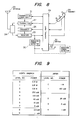
- Fig. 8 shows the construction of a telephone set used in the portable telephone system described above.
- reference numeral 23 represents an antenna and 24 does an antenna distributor for sending the reception signal from the antenna to a receiver and applying a reception signal from the receiver to the antenna 23.
- Reference numerals 24 and 26 represents frequency synthesizers for operating a transmitter 27 and a receiver 25 on predetermined channels.
- a control part 28 receives, as its input signals, the reception signal from the receiver 25, a reception level signal of the reception signal by a reception signal level detector 30 and signals from a handset 29 having a microphone M, a speaker R and key pads K, and supplies predetermined signals to the receiver 27, a transmitting power controller 31 and the frequency synthesizer 26.
- the construction of the portable telephone set is substantially the same as the construction of a mobile telephone set used in the heretofore known urban mobile telephone system (such as the telephone set described in "The Bell System Technical Journal", Vol. 58, No. 9, pp. 132), its detailed description is hereby omitted.
- the first characterizing feature of this embodiment lies in that a small output level, which is used for the private radio telephone system, is set to the output power controller 31 of the portable telephone set so that it can be used commonly for both the public cellular radio telephone system and the private radio telephone system. This is because the reception sensitivity of the local base station can be made substantially equal to that of the large area cellular radio telephone system and the distance between the portable telephone set and the station is small.
- Fig. 9 shows the levels of the output power that can be accepted by the output power controller 31 for North America and Japan.
- the minimum power is stipulated to 6 mW of the level 7, but 2.5 mW of the level 8 and 1 mW of the level 9 are further added in order to use it for the system of the present invention.
- the minimum power level is 160 mW of the step 1, but 25 mW, 5 mW and 1 mW of the levels 2, 3 and 4 are further added for the system of the present invention.
- the portable telephone set of Fig. 8 has a switch portion for the power levels necessary for communication in the cells (1 - 12) shown in Fig. 1 and the communication power levels necessary for the private radio telepone system (e.g. 0.14) inside the cell (1) described above.
- the second characterizing feature of the portableteleph- one set shown in Fig. 8 lies in that it has switch means for changing over the modes of use as desired by an operator to a mode where communication can be made by utilizing the private radio telephone system when the telephone set enters the local service area of the private radio telephone system.
- the switch 32 selects the combination of the frequency channels of the communication system of the cells (1 - 12) of Fig. 1 with the power levels and the frequency channels of the private radio telephone system (e.g. 0.14 in Fig. 1) with the transmitting power levels.
- This mode switch 32 may be of an automatic type. Namely, a reception level judging detector 33 represented by dash line in Fig. 8 is disposed. In the-public cellular radio telephone system, when the telephone set is under the waiting state where it receives the control signal from its station, it receives the time slot for calling other subscribers for the most of the time. This waste time is utilized in order.to receive the control signal in the private radio telephone system and when the reception intensity is at a sufficiently high level, the mode switch can be changed over automatically.
- the present invention provides the following effects.
Abstract
Description
- This invention relates generally to a portable radio telephone system. More particularly, the present invention relates to a private radio telephone system, for use in a local area such as in a office building or in a factory, of the type wherein when its portable telephone set is taken out from the area, it can communicate with subscribers of public telephone network through a public cellular radio telephone system which has already been in service over urban areas.
- A public cellular radio telephone system has been known in the past as a urban cellular radio telephone system. When its portable telephone set is brought into an office building or in a factory and connected to a subscriber of the private branch exchange for communication, not only the quality of telephone voice drops due to radio wave propagation attenuation by the office building but also the telephone charge of the urban cellular telephone system must be payed.
- As one of the prior art references of urban cellular radio telephone systems which improve the radio wave propagation attenuation of this kind, mention can be seen in Proceedings of IEEE-VT Conference, 1984, pp 162,
- In the portable telephone system described in the prior art reference described above, introduction of a private branch exchange which has radio telephone subscriber circuits is not taken into consideration, so that direct communication cannot be made from the portable telephone set to the subscribers of the private branch branch telephone system.
- On the other hand, if we introduce private branch radio telephone systems that have been commonly considered, the portable telephone set becomes expensive because it must have a radio frequency circuit of the private radio frequency channels in addion to the -radio frequency of the urban cellular radio telephone.
- The object of the present.invention is to accomplish a portable radio telephone system wherein a portable telephone set can be used both for an urban public cellular radio telephone system and for a private rad telephone system which is build inside a local area. For-example, the present invention is directed to accomplish a portable radio telephone system wherein direct access can be made from a portable telephone set to the radio frequency circuit of a private branch exchange without causing any radio wave interference to a heretofore known urban cellular radio telephone system
- To realize the present invention, a portable radio telephone system of the type wherein a given area is divided into a plularity of large areas, each of the large areas is further divided into a plularity of small cellular areas, wherein the reuse of the same frequency channel is permitted between the large areas, different frequency channels are allocated to the small cellular areas of each large area and public radio communicationis made by portable telephone sets by use of the radio waves of the frequency channels allocated to the small cellular areas, the object of the present invention described above can be accomplished by a private radio telephone system consisting of an antenna for transmitting and receiving a radio wave pair which doubly reuse the same frequency channel pair with the public cellular radio telephone system but do not use the frequency channels allocated to the small cellular area wherein the private telephone system exists, a private branch exchange and a transceiver both of which are connected to the antenna and private radio communication is made through private.branch exchange by use of the portable telephone sets.
- Incidently, the power intensity of the radio wave radiated from the antenna is kept to a very low intensity level so that it does not affect the public cellular radio telephone system in the large areas, and also the frequency channel pair is selected so that they hardly interfere the public cellular radio telephone system of the large areas. To prevent the occurence of the wave interference, the antenna described above may have directivity.
- When the portable radio telephone system of the present invention is disposed in a district where the density of subscribers of a public cellular radio telephone system is high, the radious of the small cellular area( cell or sector ) becomes little so that the service area of a local private system using a single antenna becomes narrow. In such a case, the local area is divided into a plularity of mini cells with each antenna and radio waves of different frequency channel pairs are reused among the mini cells to secure a required service area, as described, for example, in "Personal Communication", September, 1985, pp. 28.
- The above and other objects and also novel features of the present invention will become more apparent from the following description when taken in conjunction with the accompanying drawings.
-
- Figs. 1, 4, 6 and 7 show examples of cell disposition of a urban cellular radio telephone system of the present invention;
- Fig. 2 is an explanatory view of the intensity of a radio wave in an embodiment of the present invention;
- Figs. 3 and 5 are schematic views showing the construction of the portable radio telephone system of the present invention;
- Fig. 8 is a block diagram showing the construction of a portable telephone set used for the portable radio telephone system in one embodiment of the present invention; and
- Fig. 9 shows the output power levels at which the portable telephone set of Fig. 8 operates.
- Fig. 1 shows an example of cell disposition of a heretofore known public cellular radio telephone system in order to have the present invention more easily understood.
- A given are is divided into a plurality of large areas ( which are referred to as "cluster" ) represented by thick line and each of the clusters is divided into twelve cells ( small areas ) 1 - 12. An antenna for transmission and reception ( represented by black dot "." ) is disposed at the center of each cell.
- Radio frequency channels are allocated to each cell in the number corresponding to the traffic of the radio telephone. These radio waves will be called "f" in the
cell 1, "f2" in thecell 2, "f3" in thecell 3, and so forth. The f1, f2, ....radio waves have an allocated bandwidth, and a plurality of frequency channels exist in each bandwidth related to the radio telephone traffic. Additionally, the position of thecell 1 in thecluster 13 is selected so that the intensity of the f wave interference from outside the cluster becomes minimal. - In the portable radio telephone system of the present invention, radio communication is made between a private branch radio telephone system in one cell and a portable telephone set by use of frequencies different from the frequencies allocated to the cell.
- Incidentally, the frequency and intensity of the radio waves used for the private branch radio telephone system are selected in the following manner lest radio wave interference occurs with the other cells in the cluster. Namely, the frequency channels allocated to the
cell 1 must be the channels which are used in the most apart from thecell 1. Thus, the f2 wave of thecell 2 exists'for thecell 1. Thecell 4 is the most remote from thecell 1 inside thecluster 13, but the interference intensity of the f4 wave from outside thecluster 13 is greater than that of the f2 wave. The f3 wave used in thecell 3 also satisfies the condition described above. - Fig. 2 shows the intensity of radio wave used by the portable radio telephone system of the present invention. In other words, when the private
radio telephone system 0 of the present invention is disposed inside thecell 1 as is shown in Fig. 1, the electric field intensity E1 of the radio wave radiated from thecell 1 can be expressed by the following equation if the irregular radio wave propagation does not exist:
- In the public cellular radio telephone system, the radious of the cell are determined at a boundary where the ratio S1/I1 of the intensity S1 of the received fl wave to the intensity I1 of the f1 wave interference from outside the
cluster 13, so that the the quality of telephone voice is kept a predetermined level. - The transmitting power P2 of the private
radio telephone system 0 of the present invention is kept to a value so that the ratio of the intensity S2 of the transmitting f2 wave to the intensity I2 of the f2 wave interference at the boundary of the local service area satisfies the conditions below:
- Fig. 3 is a structural view of the portable radio telephone system in accordance with one embodiment of the present invention. A private branch exchange ( PBX ) 15 for wired telephone subscribers is disposed in the private radio telephone system 0 ( corresponding to 0 in Fig. 1 ) and radio telephone subscriber circuit are added thereto. The radio telephone subscriber circuits are connected to transmission/
reception antennas booster 17, and the f2 wave having the intensity that can supress the f2 wave interference of the public cellular radio telephone system, is transmitted from the antennas and enables the portable telephone set 20 to communicate by receiving the f2 wave from the antennas. - As will be described elswhere, the
portable telephone set 20 can communicate with the fl wave from thecell 1 of the public cellular radio telephone system. The transmitting power of theportable telephone set 20 is also determined to a value that satisfies the condition of eq. (2). This controlling is made automatically by a radio frequency controller disposed inside the the private branch exchange (PBX) 15. The method controlling the transmission power for the private radio telephone system is the same as the method used for the heretofore known public cellular radio telephone system. - Fig. 4 shows the relation of the fN wave ( N = 12 of the radio frequency channel with Fig. 1 when the private radio telephone system is disposed for each of the cells inside the
cluster 13. For example, thecells - When a plularity of private radio telephone systems are disposed for each of the cells inside one cluster, the total interference intensity must be determined below a predetermined level. However, the condition which prevents the interference to the nearest adjacent system of the present invention is far severer. As the radiation from an outdoor antenna shown in Fig. 3 is particulary severe, the interference is restricted by providing the antenna with directivity.
- Furthermore, when a plurality of private radio telephone systems exist extrimely close to one another inside the small cell, the service area of the private radio telephone system of the present invention becomes extremely narrow in order to prevent their mutual interference. To solve this problem, other radio frequency channels ( e. g. alternate use of f2 and f3 waves in the cell 1 ) are used for the adjacent private branch telephone systems.
- Fig. 5 shows the construction of the portable radio telephone system in accordance with another embodiment of the present invention. In this embodiment, a plurality of radio frequency channels are reused in one local area.
- A transceiver ( TRX ) 21 having a radio wave transceiver and an antenna is disposed inside a building while a transceiver ( TRX ) 22 is disposed outside the building, and the radio frequency channels, the transmission power and the antenna directivity are selected so that=they do not interfere with each other. The private branch exchange ( PBX ) 15 is equipped with a radio frequency controllar, and when the portable telephone set 20 moves from the f2 area to the area of f3, it detects automatically the movement and switches the channels in the same way as the public cellular radio telephone system. If the radio frequency controller selects the empty channel(s) of both the public cellular radio telephone system and the other private radio telephone systems inside the cluster, the quality of the telephone voice is highly improved.
- The district in which the portable radio telephone system of the present invention is disposed is not restricted to the cell disposition shown in Fig. 1.
- Figs. 6 and 7 show an example of sector cell allotment. Each cell is divided into six sectors and four cells = 24 sectors form a unit cluster. A multibeam antenna having 60° directivity is disposed at the center of the hexagonal cell. The frequency channel'- of each sector is reused among the clusters where a public cellular radio telephone system is in service. Fig. 7 shows the sector number of the frequency channel corresponding to Fig. 6 when the private radio telephone system of the present- invention is disposed inside each sector, and the system doubly reuses the radio frequency channel inside the sector. Other examples of sector numbers of the frequency channels can of course exist in the same way as the case of 12-cell unit sectors in Fig. 1. When the wave interference is taken into consideration for sector cells, the directivityof the antenna becomes an important factor, and the gain function G(6) must be introduced in the proportional coefficient a = aoG(θ) of eq. (1).
- In a.district where the number of subscribers of the public cellular radio telephone system becomes large, the traffic per unit area is increased by reducing the radius of the cell. The portable radio telephone system of the present invention is designed in consideration of this increase inside the respective area. Table 1 illustrates the radious of the service area of the private radio telephone system and the radious of the cell of the public cellular radio telephone system.
-

- In the actual cases, the shape of the oell is not so ideal as the ideal cell disposition shown in Fig. 1 and 6, and the power of the transmitted radio wave attenuates more rapidly than eq. (1). However, the application of the present invention is not essentially changed by these, factors.
- Fig. 8 shows the construction of a telephone set used in the portable telephone system described above.
- In the drawing,
reference numeral 23 represents an antenna and 24 does an antenna distributor for sending the reception signal from the antenna to a receiver and applying a reception signal from the receiver to theantenna 23.Reference numerals transmitter 27 and areceiver 25 on predetermined channels. Acontrol part 28 receives, as its input signals, the reception signal from thereceiver 25, a reception level signal of the reception signal by a receptionsignal level detector 30 and signals from ahandset 29 having a microphone M, a speaker R and key pads K, and supplies predetermined signals to thereceiver 27, a transmittingpower controller 31 and thefrequency synthesizer 26. - Since the construction of the portable telephone set is substantially the same as the construction of a mobile telephone set used in the heretofore known urban mobile telephone system (such as the telephone set described in "The Bell System Technical Journal", Vol. 58, No. 9, pp. 132), its detailed description is hereby omitted.
- The first characterizing feature of this embodiment lies in that a small output level, which is used for the private radio telephone system, is set to the
output power controller 31 of the portable telephone set so that it can be used commonly for both the public cellular radio telephone system and the private radio telephone system. This is because the reception sensitivity of the local base station can be made substantially equal to that of the large area cellular radio telephone system and the distance between the portable telephone set and the station is small. - Fig. 9 shows the levels of the output power that can be accepted by the
output power controller 31 for North America and Japan. In the case of the public cellular radio telephone system of North America, the minimum power is stipulated to 6 mW of thelevel 7, but 2.5 mW of thelevel level 9 are further added in order to use it for the system of the present invention. In the case of the public cellular radio telephone system of Japan, the minimum power level is 160 mW of thestep 1, but 25 mW, 5 mW and 1 mW of thelevels - In other words, the portable telephone set of Fig. 8 has a switch portion for the power levels necessary for communication in the cells (1 - 12) shown in Fig. 1 and the communication power levels necessary for the private radio telepone system (e.g. 0.14) inside the cell (1) described above.
- The second characterizing feature of the portableteleph- one set shown in Fig. 8 lies in that it has switch means for changing over the modes of use as desired by an operator to a mode where communication can be made by utilizing the private radio telephone system when the telephone set enters the local service area of the private radio telephone system.
- When the
mode switch 32 is manually changed from the contact P to C, the frequency channel of thefrequency synthesizer 26 and the level range of the transmittingpower controller 31 are forcedly set to the state where the control signal of the private radio telephone system can be received. In other words, theswitch 32 selects the combination of the frequency channels of the communication system of the cells (1 - 12) of Fig. 1 with the power levels and the frequency channels of the private radio telephone system (e.g. 0.14 in Fig. 1) with the transmitting power levels. - This
mode switch 32 may be of an automatic type. Namely, a reception level judging detector 33 represented by dash line in Fig. 8 is disposed. In the-public cellular radio telephone system, when the telephone set is under the waiting state where it receives the control signal from its station, it receives the time slot for calling other subscribers for the most of the time. This waste time is utilized in order.to receive the control signal in the private radio telephone system and when the reception intensity is at a sufficiently high level, the mode switch can be changed over automatically. - As described above, the present invention provides the following effects.
-
- (1) In accordance with the present invention, the radio frequency channels used in the existing public cellular radio frequency system are reused when disposing a private radio telephone system. Accordingly, the use of new frequency resources is not necessary.
- (2) In accordance with the present invention, when the portable telephone set is brought into an area where the public cellular radio telephone system is in service, direct access can be made from the telephone set.. Accordingly, radio wave attenuation due to buildings or the like does not occur and the toll for the public cellular radio telephone system is not necessary.
- (3) In accordance with the present invention, the mobile telephone set that can make direct access to both the public cellular radio telephone system and the. private radio telephone system can be accomplished without increasing a radio frequency circuit at the portable telephone set. Therefore, the portable set can be made compact in size and simple in construction and can be produced economically.
Claims (6)
Applications Claiming Priority (2)
| Application Number | Priority Date | Filing Date | Title |
|---|---|---|---|
| JP276749/85 | 1985-12-11 | ||
| JP60276749A JPH0746877B2 (en) | 1985-12-11 | 1985-12-11 | Mobile radio communication system |
Publications (3)
| Publication Number | Publication Date |
|---|---|
| EP0225607A2 true EP0225607A2 (en) | 1987-06-16 |
| EP0225607A3 EP0225607A3 (en) | 1989-03-29 |
| EP0225607B1 EP0225607B1 (en) | 1993-09-22 |
Family
ID=17573804
Family Applications (1)
| Application Number | Title | Priority Date | Filing Date |
|---|---|---|---|
| EP86116857A Expired - Lifetime EP0225607B1 (en) | 1985-12-11 | 1986-12-04 | Portable radio telephone system |
Country Status (6)
| Country | Link |
|---|---|
| US (1) | US4790000A (en) |
| EP (1) | EP0225607B1 (en) |
| JP (1) | JPH0746877B2 (en) |
| CA (1) | CA1253213A (en) |
| DE (1) | DE3689064T2 (en) |
| HK (1) | HK84394A (en) |
Cited By (16)
| Publication number | Priority date | Publication date | Assignee | Title |
|---|---|---|---|---|
| EP0374787A2 (en) * | 1988-12-23 | 1990-06-27 | Alcatel SEL Aktiengesellschaft | Radio telephone system in private branch exchange configuration |
| EP0492051A1 (en) * | 1990-12-10 | 1992-07-01 | Robert Bosch Gmbh | Radiotelephone network enabling communication outside the coverage zone |
| FR2687872A1 (en) * | 1992-02-06 | 1993-08-27 | Motorola Inc | APPARATUS AND METHOD FOR SELECTING BETWEEN SEVERAL RADIOTELEPHONE SYSTEMS. |
| FR2687874A1 (en) * | 1992-02-06 | 1993-08-27 | Motorola Inc | RADIOTELEPHONE APPARATUS OPERATING IN A DUAL, CORDLESS AND CELLULAR SYSTEM, AND ITS OPERATING METHOD. |
| FR2687873A1 (en) * | 1992-02-06 | 1993-08-27 | Motorola Inc | FREQUENCY-SHARING TELECOMMUNICATIONS SYSTEM BETWEEN SEVERAL RADIOTELEPHONE SYSTEMS, APPARATUS AND METHOD THEREOF. |
| FR2693067A1 (en) * | 1992-06-23 | 1993-12-31 | Motorola Inc | Radiotelephone apparatus for dual system, cellular and wireless, and method of implementation, allowing a reduction in channel control time. |
| EP0600695A2 (en) * | 1992-12-03 | 1994-06-08 | Xerox Corporation | Wireless communications using near field coupling |
| EP0644666A1 (en) * | 1993-09-21 | 1995-03-22 | Nhk Integrated Technology Inc. | Medium-frequency radio transmission system |
| WO1995012957A1 (en) * | 1993-11-04 | 1995-05-11 | Ericsson Inc. | Radio personal communications system |
| WO1995024106A1 (en) * | 1994-03-03 | 1995-09-08 | Ericsson Inc. | Secure radio personal communications system and method |
| FR2717970A1 (en) * | 1994-03-22 | 1995-09-29 | Tassy Alain | Radio telephone installation for cellular network within public building |
| GB2304495A (en) * | 1995-08-15 | 1997-03-19 | Nokia Mobile Phones Ltd | Radio Resource Management In Potentially Interfering Communications Systems |
| US5634193A (en) * | 1992-03-24 | 1997-05-27 | Telefonaktiebolaget Lm Ericsson | Method of locating a mobile station in a mobile telephone system having indoor and outdoor base stations |
| GB2307622A (en) * | 1995-06-01 | 1997-05-28 | Nec Corp | Personal handy phone system |
| US5924030A (en) * | 1995-09-29 | 1999-07-13 | Nokia Mobile Phones Limited | Cellular extension of a fixed communications network |
| GB2338865A (en) * | 1998-06-27 | 1999-12-29 | Motorola Ltd | Cellular communication system and methods therefor |
Families Citing this family (89)
| Publication number | Priority date | Publication date | Assignee | Title |
|---|---|---|---|---|
| FR2620887B1 (en) * | 1987-09-18 | 1990-01-19 | Applic Electro Tech Avance | RADIO-LINKED TELEPHONE INSTALLATION |
| JPH0722424B2 (en) * | 1987-09-21 | 1995-03-08 | 株式会社日立製作所 | Mobile radio communication system |
| US4989230A (en) * | 1988-09-23 | 1991-01-29 | Motorola, Inc. | Cellular cordless telephone |
| US5127042A (en) * | 1988-09-23 | 1992-06-30 | Motorola, Inc. | Cellular cordless telephone |
| US5193109A (en) * | 1989-02-06 | 1993-03-09 | Pactel Corporation | Zoned microcell with sector scanning for cellular telephone system |
| US4932049A (en) * | 1989-02-06 | 1990-06-05 | Pactel Corporation | Cellular telephone system |
| US5067147A (en) * | 1989-11-07 | 1991-11-19 | Pactel Corporation | Microcell system for cellular telephone system |
| US5301353A (en) * | 1990-02-12 | 1994-04-05 | Motorola, Inc. | Communication system and apparatus |
| SE465992B (en) * | 1990-04-10 | 1991-11-25 | Ericsson Telefon Ab L M | MOBILE PHONE SYSTEM PROVIDED TO USE BY SUBSCRIBERS INDOOR AND OUTDOOR |
| US5093925A (en) * | 1990-04-25 | 1992-03-03 | Motorola, Inc. | Three dimensional cellular communication system with coordinate offset and frequency reuse |
| CA2041752A1 (en) * | 1990-05-02 | 1991-11-03 | Roland E. Williams | Private cellular telephone system |
| SE466374B (en) * | 1990-06-25 | 1992-02-03 | Ericsson Telefon Ab L M | MOBILE SYSTEMS |
| WO1992004796A1 (en) * | 1990-09-04 | 1992-03-19 | Motorola, Inc. | Cordless telephone system for residential, business and public telepoint operation |
| JP2809872B2 (en) * | 1990-11-29 | 1998-10-15 | 松下電器産業株式会社 | Mobile communication device |
| US5504936A (en) * | 1991-04-02 | 1996-04-02 | Airtouch Communications Of California | Microcells for digital cellular telephone systems |
| CA2043127C (en) * | 1991-05-23 | 1996-05-07 | Martin Handforth | Wireless communication zone management system |
| CA2068009C (en) * | 1991-08-19 | 1998-05-19 | Richard Norman Ames | System for decentralizing uplink network control and minimizing overhead in radio frequency data communications network |
| US5475866A (en) * | 1991-08-27 | 1995-12-12 | Motorola Inc. | System for informing secondary users of which radio channels are usable in which geographic region |
| SE468965B (en) * | 1991-08-30 | 1993-04-19 | Ericsson Telefon Ab L M | COMBINED MOBILE RADIO SYSTEM |
| US5842129A (en) * | 1991-10-11 | 1998-11-24 | Matsushita Electric Industrial Co., Ltd. | Portable radio telephone equipment used for CMTS/MCS in common |
| JP2643689B2 (en) * | 1991-10-21 | 1997-08-20 | 松下電器産業株式会社 | Channel allocation method in microcellular system |
| US5349631A (en) * | 1991-11-21 | 1994-09-20 | Airtouch Communications | Inbuilding telephone communication system |
| US5504803A (en) * | 1991-11-25 | 1996-04-02 | Matsushita Electric Industrial Co., Ltd. | Method for automatic mode selection for a dual-mode telephone handset for use in a cellular mobile telephone system and in a wireless telephone system |
| CA2058737C (en) * | 1992-01-03 | 1997-03-18 | Andrew S. Beasley | Rf repeater arrangement with improved frequency reuse for wireless telephones |
| GB2271040B (en) * | 1992-02-06 | 1995-11-08 | Motorola Inc | Call routing for a radiotelephone in multiple radiotelephone systems |
| US5448619A (en) * | 1992-04-14 | 1995-09-05 | Orion Industries, Inc. | Apparatus and a method of allowing private cellular operation within an existing public cellular system |
| CA2118717A1 (en) * | 1992-08-03 | 1994-02-17 | Kenneth A. Felix | Wireless pbx system using frequency scanner for channel identification |
| US5303287A (en) * | 1992-08-13 | 1994-04-12 | Hughes Aircraft Company | Integrated personal/cellular communications system architecture |
| US5627879A (en) * | 1992-09-17 | 1997-05-06 | Adc Telecommunications, Inc. | Cellular communications system with centralized base stations and distributed antenna units |
| US5561845A (en) * | 1992-10-02 | 1996-10-01 | Orion Industries, Inc. | Apparatus and method for preserving coverage in an overlapping coverage area |
| WO1994014252A1 (en) * | 1992-12-14 | 1994-06-23 | Motorola Inc. | Rf communication system using waveguide disposed within modular furnishings |
| DE4307966C2 (en) * | 1993-03-12 | 2001-04-05 | Siemens Ag | Mobile radio system |
| US5521961A (en) * | 1993-03-26 | 1996-05-28 | Celcore, Inc. | Mobility management method for delivering calls in a microcellular network |
| US5487101A (en) * | 1993-03-26 | 1996-01-23 | Celcore, Inc. | Off-load cellular system for off-loading cellular service from a main cellular system to increase cellular service capacity |
| US5422930A (en) * | 1993-05-20 | 1995-06-06 | Motorola, Inc. | Method and apparatus for sharing radio frequency spectrum in a radio frequency communication system |
| EP0661837A4 (en) * | 1993-06-17 | 1999-03-24 | Toshiba Kk | Mobile radio communication system and fixed and mobile units used therefor. |
| US5771453A (en) * | 1993-11-04 | 1998-06-23 | Ericsson Inc. | Multiple user base stations and methods for radio personal communications systems |
| ATE265127T1 (en) | 1994-02-24 | 2004-05-15 | Gte Wireless Service Corp | CELLULAR RADIO TELEPHONE WITH DIAL NUMBER ANALYSIS |
| US6453178B1 (en) | 1994-02-24 | 2002-09-17 | Gte Wireless Service Corporation | Radiotelephone operating method with connected NPA dialing analysis |
| US5594782A (en) | 1994-02-24 | 1997-01-14 | Gte Mobile Communications Service Corporation | Multiple mode personal wireless communications system |
| CN1168329C (en) | 1994-02-24 | 2004-09-22 | Gte无线服务公司 | Cellular radiotelephone system with remote programmable moving station |
| US5537459A (en) * | 1994-06-17 | 1996-07-16 | Price; Evelyn C. | Multilevel cellular communication system for hospitals |
| AU2864995A (en) * | 1994-06-17 | 1996-01-15 | Evelyn C. Price | Multilevel wireless communication system for hospitals |
| US5564121A (en) * | 1994-08-18 | 1996-10-08 | Northern Telecom Limited | Microcell layout having directional and omnidirectional antennas defining a rectilinear layout in a building |
| US5633915A (en) * | 1995-05-16 | 1997-05-27 | Southern Methodist University | Multilayered arrangement for load sharing in a cellular communication system |
| US5675629A (en) | 1995-09-08 | 1997-10-07 | At&T | Cordless cellular system base station |
| US5911120A (en) | 1995-09-08 | 1999-06-08 | At&T Wireless Services | Wireless communication system having mobile stations establish a communication link through the base station without using a landline or regional cellular network and without a call in progress |
| US5815813A (en) * | 1995-11-24 | 1998-09-29 | Northern Telecom Limited | Multipath tolerant cellular communication system and method |
| US5794151A (en) * | 1995-12-22 | 1998-08-11 | Motorola, Inc. | Frequency allocation for shared spectrum transmitter based on location |
| US5978362A (en) * | 1996-02-06 | 1999-11-02 | Airtouch Communications, Inc. | Method and apparatus for eliminating intermodulation interference in cellular telephone systems |
| US5890064A (en) * | 1996-03-13 | 1999-03-30 | Telefonaktiebolaget L M Ericsson (Publ) | Mobile telecommunications network having integrated wireless office system |
| US5913163A (en) * | 1996-03-14 | 1999-06-15 | Telefonaktiebolaget Lm Ericsson | Integrated local communication system |
| US5983100A (en) * | 1996-03-14 | 1999-11-09 | Telefonaktiebolaget Lm Ericsson | Circuit assembly for effectuating communication between a first and a second locally-positioned communication device |
| US6643523B2 (en) * | 1996-03-26 | 2003-11-04 | British Telecommunications Public Limited Company | Alternative routing system for mobile telephone calls |
| JP2917907B2 (en) * | 1996-05-07 | 1999-07-12 | 株式会社日立製作所 | Mobile radio communication system |
| JP2917906B2 (en) * | 1996-05-07 | 1999-07-12 | 株式会社日立製作所 | Mobile radio communication system |
| JP2917908B2 (en) * | 1996-05-07 | 1999-07-12 | 株式会社日立製作所 | Mobile radio communication system |
| US6041242A (en) * | 1996-06-21 | 2000-03-21 | Coulthard; Steve M. | Portable emergency response communications system and method |
| US5822698A (en) * | 1996-08-08 | 1998-10-13 | Northern Telecom Limited | Microcell frequency planning |
| US5930728A (en) * | 1996-08-29 | 1999-07-27 | Ericsson Inc. | Up converted home base station |
| US5946622A (en) * | 1996-11-19 | 1999-08-31 | Ericsson Inc. | Method and apparatus for providing cellular telephone service to a macro-cell and pico-cell within a building using shared equipment |
| US6112086A (en) | 1997-02-25 | 2000-08-29 | Adc Telecommunications, Inc. | Scanning RSSI receiver system using inverse fast fourier transforms for a cellular communications system with centralized base stations and distributed antenna units |
| WO1998039936A2 (en) * | 1997-03-03 | 1998-09-11 | Salbu Research And Development (Proprietary) Limited | Cellular communication system with mobile stations acting as relay stations |
| US6131031A (en) * | 1997-10-10 | 2000-10-10 | Watkins- Johnson Company | System and method for an underlay cellular system |
| EP0914013B1 (en) | 1997-10-17 | 2005-12-21 | Nortel Matra Cellular | Apparatus and method for frequency band scanning in a mobile communication system |
| US6141531A (en) * | 1997-11-26 | 2000-10-31 | Direct Wireless Corporation | Local wireless communication system with external communications link |
| KR100289284B1 (en) * | 1997-12-27 | 2001-05-02 | 박종섭 | Apparatus for controlling forward power of bts of mobile communication system and control method therefor |
| US6792260B1 (en) * | 1998-04-17 | 2004-09-14 | Nec Corporation | Automatic radio wave output limiting system for portable telephone set |
| US6374078B1 (en) | 1998-04-17 | 2002-04-16 | Direct Wireless Corporation | Wireless communication system with multiple external communication links |
| US6470184B1 (en) * | 1998-09-11 | 2002-10-22 | Nec Corporation | Mobile communication system in which traffics are equalized |
| AU7346800A (en) | 1999-09-02 | 2001-03-26 | Automated Business Companies | Communication and proximity authorization systems |
| US6704545B1 (en) | 2000-07-19 | 2004-03-09 | Adc Telecommunications, Inc. | Point-to-multipoint digital radio frequency transport |
| US8265637B2 (en) | 2000-08-02 | 2012-09-11 | Atc Technologies, Llc | Systems and methods for modifying antenna radiation patterns of peripheral base stations of a terrestrial network to allow reduced interference |
| US7558568B2 (en) * | 2003-07-28 | 2009-07-07 | Atc Technologies, Llc | Systems and methods for modifying antenna radiation patterns of peripheral base stations of a terrestrial network to allow reduced interference |
| US7184728B2 (en) | 2002-02-25 | 2007-02-27 | Adc Telecommunications, Inc. | Distributed automatic gain control system |
| US7039399B2 (en) | 2002-03-11 | 2006-05-02 | Adc Telecommunications, Inc. | Distribution of wireless telephony and data signals in a substantially closed environment |
| US7263293B2 (en) * | 2002-06-10 | 2007-08-28 | Andrew Corporation | Indoor wireless voice and data distribution system |
| US8958789B2 (en) * | 2002-12-03 | 2015-02-17 | Adc Telecommunications, Inc. | Distributed digital antenna system |
| FI20030929A (en) * | 2003-06-19 | 2004-12-20 | Nokia Corp | Procedure and arrangement for conducting wireless information transmission in a means of communication |
| US7599711B2 (en) * | 2006-04-12 | 2009-10-06 | Adc Telecommunications, Inc. | Systems and methods for analog transport of RF voice/data communications |
| US8583100B2 (en) * | 2007-01-25 | 2013-11-12 | Adc Telecommunications, Inc. | Distributed remote base station system |
| US8737454B2 (en) | 2007-01-25 | 2014-05-27 | Adc Telecommunications, Inc. | Modular wireless communications platform |
| US8160656B2 (en) * | 2007-05-08 | 2012-04-17 | Continental Automotive Systems, Inc. | Telematics system and method having combined cellular and satellite functionality |
| JP4925925B2 (en) * | 2007-05-30 | 2012-05-09 | ソフトバンクBb株式会社 | Radio relay apparatus and control method of radio relay apparatus |
| US8437741B2 (en) | 2008-12-19 | 2013-05-07 | Tecore | Intelligent network access controller and method |
| US8825011B2 (en) | 2008-12-19 | 2014-09-02 | Tecore, Inc. | Intelligent network access control |
| US9001811B2 (en) * | 2009-05-19 | 2015-04-07 | Adc Telecommunications, Inc. | Method of inserting CDMA beacon pilots in output of distributed remote antenna nodes |
| EP3108627A4 (en) | 2014-02-18 | 2017-10-11 | CommScope Technologies LLC | Selectively combining uplink signals in distributed antenna systems |
| US10499269B2 (en) | 2015-11-12 | 2019-12-03 | Commscope Technologies Llc | Systems and methods for assigning controlled nodes to channel interfaces of a controller |
Citations (4)
| Publication number | Priority date | Publication date | Assignee | Title |
|---|---|---|---|---|
| DE2365043A1 (en) * | 1973-10-17 | 1975-04-30 | Motorola Inc | RADIO TELEPHONE SYSTEM WITH PORTABLE OR MOBILE UNITS |
| US4144411A (en) * | 1976-09-22 | 1979-03-13 | Bell Telephone Laboratories, Incorporated | Cellular radiotelephone system structured for flexible use of different cell sizes |
| EP0188322A2 (en) * | 1985-01-08 | 1986-07-23 | Shaye Communications Limited | A total communication system and communication apparatus for use in such a system |
| EP0169726B1 (en) * | 1984-07-25 | 1991-02-06 | Racal Research Limited | Portable telephones |
Family Cites Families (10)
| Publication number | Priority date | Publication date | Assignee | Title |
|---|---|---|---|---|
| US3955140A (en) * | 1975-05-20 | 1976-05-04 | Public Systems, Inc. | Mobile radio extension unit with punch through operation |
| JPS58151136A (en) * | 1982-03-04 | 1983-09-08 | Nec Corp | Mobile radio communication system |
| JPS58204640A (en) * | 1982-05-22 | 1983-11-29 | T D L Kk | Portable telephone set |
| JPS5927636A (en) * | 1982-08-06 | 1984-02-14 | Nec Corp | Radio communication system |
| US4539706A (en) * | 1983-02-03 | 1985-09-03 | General Electric Company | Mobile vehicular repeater system which provides up-link acknowledgement signal to portable transceiver at end of transceiver transmission |
| JPS60236335A (en) * | 1984-05-09 | 1985-11-25 | Nec Corp | Portable radio communication method |
| EP0193316B1 (en) * | 1985-02-18 | 1989-09-27 | Nec Corporation | Mobile telephone system for automatically paging absent mobile subscriber |
| SE448199B (en) * | 1985-05-09 | 1987-01-26 | Ericsson Telefon Ab L M | INSTALLATION WITH MULTIPLE BERBARA, CORDLESS PHONE DEVICES |
| US4659878A (en) * | 1985-09-11 | 1987-04-21 | General Electric Company | Method and apparatus for interference free communications between a remote handset and a host subscriber unit in a Cellular Radio Telephone System |
| US4672658A (en) * | 1985-10-16 | 1987-06-09 | At&T Company And At&T Bell Laboratories | Spread spectrum wireless PBX |
-
1985
- 1985-12-11 JP JP60276749A patent/JPH0746877B2/en not_active Expired - Fee Related
-
1986
- 1986-12-04 DE DE86116857T patent/DE3689064T2/en not_active Expired - Fee Related
- 1986-12-04 EP EP86116857A patent/EP0225607B1/en not_active Expired - Lifetime
- 1986-12-10 US US06/940,489 patent/US4790000A/en not_active Expired - Lifetime
- 1986-12-11 CA CA000525054A patent/CA1253213A/en not_active Expired
-
1994
- 1994-08-18 HK HK84394A patent/HK84394A/en not_active IP Right Cessation
Patent Citations (4)
| Publication number | Priority date | Publication date | Assignee | Title |
|---|---|---|---|---|
| DE2365043A1 (en) * | 1973-10-17 | 1975-04-30 | Motorola Inc | RADIO TELEPHONE SYSTEM WITH PORTABLE OR MOBILE UNITS |
| US4144411A (en) * | 1976-09-22 | 1979-03-13 | Bell Telephone Laboratories, Incorporated | Cellular radiotelephone system structured for flexible use of different cell sizes |
| EP0169726B1 (en) * | 1984-07-25 | 1991-02-06 | Racal Research Limited | Portable telephones |
| EP0188322A2 (en) * | 1985-01-08 | 1986-07-23 | Shaye Communications Limited | A total communication system and communication apparatus for use in such a system |
Non-Patent Citations (1)
| Title |
|---|
| IEEE TRANSACTIONS ON VEHICULAR TECHNOLOGY, vol. VT-34, no. 3, August 1983, pages 117-121, IEEE, New York, US; D.C. COX: "Universal portable radio communications" * |
Cited By (33)
| Publication number | Priority date | Publication date | Assignee | Title |
|---|---|---|---|---|
| EP0374787A3 (en) * | 1988-12-23 | 1992-01-15 | Alcatel SEL Aktiengesellschaft | Radio telephone system in private branch exchange configuration |
| US5133001A (en) * | 1988-12-23 | 1992-07-21 | Standard Elektrik Lorenz A.G. | Radiotelephone system in the form of a private branch exchange |
| EP0374787A2 (en) * | 1988-12-23 | 1990-06-27 | Alcatel SEL Aktiengesellschaft | Radio telephone system in private branch exchange configuration |
| EP0492051A1 (en) * | 1990-12-10 | 1992-07-01 | Robert Bosch Gmbh | Radiotelephone network enabling communication outside the coverage zone |
| CN1047270C (en) * | 1992-02-06 | 1999-12-08 | 摩托罗拉公司 | Apparatus and method for alternative radiotelephone system selection |
| FR2687872A1 (en) * | 1992-02-06 | 1993-08-27 | Motorola Inc | APPARATUS AND METHOD FOR SELECTING BETWEEN SEVERAL RADIOTELEPHONE SYSTEMS. |
| FR2687874A1 (en) * | 1992-02-06 | 1993-08-27 | Motorola Inc | RADIOTELEPHONE APPARATUS OPERATING IN A DUAL, CORDLESS AND CELLULAR SYSTEM, AND ITS OPERATING METHOD. |
| FR2687873A1 (en) * | 1992-02-06 | 1993-08-27 | Motorola Inc | FREQUENCY-SHARING TELECOMMUNICATIONS SYSTEM BETWEEN SEVERAL RADIOTELEPHONE SYSTEMS, APPARATUS AND METHOD THEREOF. |
| US5634193A (en) * | 1992-03-24 | 1997-05-27 | Telefonaktiebolaget Lm Ericsson | Method of locating a mobile station in a mobile telephone system having indoor and outdoor base stations |
| FR2693067A1 (en) * | 1992-06-23 | 1993-12-31 | Motorola Inc | Radiotelephone apparatus for dual system, cellular and wireless, and method of implementation, allowing a reduction in channel control time. |
| EP0600695A2 (en) * | 1992-12-03 | 1994-06-08 | Xerox Corporation | Wireless communications using near field coupling |
| US5437057A (en) * | 1992-12-03 | 1995-07-25 | Xerox Corporation | Wireless communications using near field coupling |
| EP0600695A3 (en) * | 1992-12-03 | 1995-01-18 | Xerox Corp | Wireless communications using near field coupling. |
| KR100297507B1 (en) * | 1993-09-21 | 2001-10-24 | 닛폰 호소 교카이 | Medium Radio Transmission System |
| EP0644666A1 (en) * | 1993-09-21 | 1995-03-22 | Nhk Integrated Technology Inc. | Medium-frequency radio transmission system |
| US5689804A (en) * | 1993-09-21 | 1997-11-18 | Nhk Integrated Technology Inc. | Medium-frequency radio transmission system |
| US5537637A (en) * | 1993-09-21 | 1996-07-16 | Nhk Integrated Technology, Inc. | Medium-frequency radio broadcasting retransmission system for confined and electromagnetically shielded areas |
| US5535259A (en) * | 1993-11-04 | 1996-07-09 | Ericsson Inc. | Radio personal communications system and method for allocating frequencies for communications between a cellular terminal and a base station |
| WO1995012957A1 (en) * | 1993-11-04 | 1995-05-11 | Ericsson Inc. | Radio personal communications system |
| US5526402A (en) * | 1993-11-04 | 1996-06-11 | Ericsson Inc. | Radio personal communications system and method for initiating communications between a base station and a cellular terminal |
| US5581597A (en) * | 1993-11-04 | 1996-12-03 | Ericsson Inc. | Radio personal communications system and method for selecting a frequency for use in communications between a base station and a cellular terminal |
| US5812955A (en) * | 1993-11-04 | 1998-09-22 | Ericsson Inc. | Base station which relays cellular verification signals via a telephone wire network to verify a cellular radio telephone |
| US6256514B1 (en) | 1993-11-04 | 2001-07-03 | Ericsson, Inc. | Secure radio personal communications system and method |
| WO1995024106A1 (en) * | 1994-03-03 | 1995-09-08 | Ericsson Inc. | Secure radio personal communications system and method |
| AU686768B2 (en) * | 1994-03-03 | 1998-02-12 | Ericsson Inc. | Secure radio personal communications system and method |
| FR2717970A1 (en) * | 1994-03-22 | 1995-09-29 | Tassy Alain | Radio telephone installation for cellular network within public building |
| US5818918A (en) * | 1995-01-06 | 1998-10-06 | Nec Corporation | Personal handy phone system |
| GB2307622A (en) * | 1995-06-01 | 1997-05-28 | Nec Corp | Personal handy phone system |
| GB2307622B (en) * | 1995-06-01 | 1999-08-18 | Nec Corp | Personal handy phone system |
| GB2304495B (en) * | 1995-08-15 | 1999-12-29 | Nokia Mobile Phones Ltd | Radio resource sharing |
| GB2304495A (en) * | 1995-08-15 | 1997-03-19 | Nokia Mobile Phones Ltd | Radio Resource Management In Potentially Interfering Communications Systems |
| US5924030A (en) * | 1995-09-29 | 1999-07-13 | Nokia Mobile Phones Limited | Cellular extension of a fixed communications network |
| GB2338865A (en) * | 1998-06-27 | 1999-12-29 | Motorola Ltd | Cellular communication system and methods therefor |
Also Published As
| Publication number | Publication date |
|---|---|
| JPH0746877B2 (en) | 1995-05-17 |
| EP0225607B1 (en) | 1993-09-22 |
| JPS62136930A (en) | 1987-06-19 |
| DE3689064D1 (en) | 1993-10-28 |
| CA1253213A (en) | 1989-04-25 |
| DE3689064T2 (en) | 1994-05-05 |
| EP0225607A3 (en) | 1989-03-29 |
| US4790000A (en) | 1988-12-06 |
| HK84394A (en) | 1994-08-26 |
Similar Documents
| Publication | Publication Date | Title |
|---|---|---|
| US4790000A (en) | Portable radio telephone system | |
| US4144496A (en) | Mobile communication system and method employing frequency reuse within a geographical service area | |
| US5432780A (en) | High capacity sectorized cellular communication system | |
| US7272362B2 (en) | Multi-sector in-building repeater | |
| US5546443A (en) | Communication management technique for a radiotelephone system including microcells | |
| US5067147A (en) | Microcell system for cellular telephone system | |
| US4392242A (en) | Mobile communication system | |
| JP3382945B2 (en) | General mobile communication system | |
| US4704733A (en) | Cell enhancer for cellular radio telephone system having diversity function | |
| US5901342A (en) | Establishment of a call in a mobile communication system | |
| EP0359535B1 (en) | High capacity sectorized cellular communication system | |
| WO1998033338A2 (en) | Point to multipoint radio access system | |
| EP0690637A2 (en) | Method and system for providing a digital wireless local loop | |
| CA2041705A1 (en) | Method and apparatus for providing wireless communications between remote locations | |
| GB1586260A (en) | Radio telecommunications system | |
| EP0500654A1 (en) | Zoned microcell with sector scanning for cellular telephone systems | |
| EP1064758B1 (en) | Method and system for wireless telecommunications | |
| Stocker | Small-cell mobile phone systems | |
| JP2917906B2 (en) | Mobile radio communication system | |
| JPH0847032A (en) | Method and system for supplying subscriber's circuit of radio system | |
| JP2917908B2 (en) | Mobile radio communication system | |
| JP2917907B2 (en) | Mobile radio communication system | |
| CA1336519C (en) | High capacity sectorized cellular communication system | |
| GB2237478A (en) | Radio telephony system | |
| CA1039362A (en) | Radio telephone system |
Legal Events
| Date | Code | Title | Description |
|---|---|---|---|
| PUAI | Public reference made under article 153(3) epc to a published international application that has entered the european phase |
Free format text: ORIGINAL CODE: 0009012 |
|
| 17P | Request for examination filed |
Effective date: 19861204 |
|
| AK | Designated contracting states |
Kind code of ref document: A2 Designated state(s): DE FR GB |
|
| PUAL | Search report despatched |
Free format text: ORIGINAL CODE: 0009013 |
|
| AK | Designated contracting states |
Kind code of ref document: A3 Designated state(s): DE FR GB |
|
| 17Q | First examination report despatched |
Effective date: 19910821 |
|
| GRAA | (expected) grant |
Free format text: ORIGINAL CODE: 0009210 |
|
| AK | Designated contracting states |
Kind code of ref document: B1 Designated state(s): DE FR GB |
|
| REF | Corresponds to: |
Ref document number: 3689064 Country of ref document: DE Date of ref document: 19931028 |
|
| ET | Fr: translation filed | ||
| PLBE | No opposition filed within time limit |
Free format text: ORIGINAL CODE: 0009261 |
|
| STAA | Information on the status of an ep patent application or granted ep patent |
Free format text: STATUS: NO OPPOSITION FILED WITHIN TIME LIMIT |
|
| 26N | No opposition filed | ||
| REG | Reference to a national code |
Ref country code: GB Ref legal event code: IF02 |
|
| PGFP | Annual fee paid to national office [announced via postgrant information from national office to epo] |
Ref country code: GB Payment date: 20041125 Year of fee payment: 19 |
|
| PGFP | Annual fee paid to national office [announced via postgrant information from national office to epo] |
Ref country code: FR Payment date: 20041202 Year of fee payment: 19 |
|
| PGFP | Annual fee paid to national office [announced via postgrant information from national office to epo] |
Ref country code: DE Payment date: 20041206 Year of fee payment: 19 |
|
| PG25 | Lapsed in a contracting state [announced via postgrant information from national office to epo] |
Ref country code: GB Free format text: LAPSE BECAUSE OF NON-PAYMENT OF DUE FEES Effective date: 20051204 |
|
| PG25 | Lapsed in a contracting state [announced via postgrant information from national office to epo] |
Ref country code: DE Free format text: LAPSE BECAUSE OF NON-PAYMENT OF DUE FEES Effective date: 20060701 |
|
| GBPC | Gb: european patent ceased through non-payment of renewal fee |
Effective date: 20051204 |
|
| PG25 | Lapsed in a contracting state [announced via postgrant information from national office to epo] |
Ref country code: FR Free format text: LAPSE BECAUSE OF NON-PAYMENT OF DUE FEES Effective date: 20060831 |
|
| REG | Reference to a national code |
Ref country code: FR Ref legal event code: ST Effective date: 20060831 |