EP0226426B1 - Two speed gearbox - Google Patents
Two speed gearbox Download PDFInfo
- Publication number
- EP0226426B1 EP0226426B1 EP86309544A EP86309544A EP0226426B1 EP 0226426 B1 EP0226426 B1 EP 0226426B1 EP 86309544 A EP86309544 A EP 86309544A EP 86309544 A EP86309544 A EP 86309544A EP 0226426 B1 EP0226426 B1 EP 0226426B1
- Authority
- EP
- European Patent Office
- Prior art keywords
- clutch
- output shaft
- gearbox
- slidable coupling
- low speed
- Prior art date
- Legal status (The legal status is an assumption and is not a legal conclusion. Google has not performed a legal analysis and makes no representation as to the accuracy of the status listed.)
- Expired
Links
- 230000008878 coupling Effects 0.000 claims description 52
- 238000010168 coupling process Methods 0.000 claims description 52
- 238000005859 coupling reaction Methods 0.000 claims description 52
- 230000007246 mechanism Effects 0.000 claims description 18
- 230000009467 reduction Effects 0.000 claims description 12
- 230000033001 locomotion Effects 0.000 claims description 11
- 230000006835 compression Effects 0.000 claims description 10
- 238000007906 compression Methods 0.000 claims description 10
- 239000012530 fluid Substances 0.000 claims description 5
- 230000008859 change Effects 0.000 description 10
- 238000000034 method Methods 0.000 description 3
- 241000282472 Canis lupus familiaris Species 0.000 description 2
- 230000001105 regulatory effect Effects 0.000 description 2
- 238000007792 addition Methods 0.000 description 1
- 230000008901 benefit Effects 0.000 description 1
- 230000005540 biological transmission Effects 0.000 description 1
- 230000000694 effects Effects 0.000 description 1
- 238000005096 rolling process Methods 0.000 description 1
Images


Classifications
-
- F—MECHANICAL ENGINEERING; LIGHTING; HEATING; WEAPONS; BLASTING
- F16—ENGINEERING ELEMENTS AND UNITS; GENERAL MEASURES FOR PRODUCING AND MAINTAINING EFFECTIVE FUNCTIONING OF MACHINES OR INSTALLATIONS; THERMAL INSULATION IN GENERAL
- F16H—GEARING
- F16H3/00—Toothed gearings for conveying rotary motion with variable gear ratio or for reversing rotary motion
- F16H3/44—Toothed gearings for conveying rotary motion with variable gear ratio or for reversing rotary motion using gears having orbital motion
- F16H3/46—Gearings having only two central gears, connected by orbital gears
- F16H3/48—Gearings having only two central gears, connected by orbital gears with single orbital gears or pairs of rigidly-connected orbital gears
- F16H3/52—Gearings having only two central gears, connected by orbital gears with single orbital gears or pairs of rigidly-connected orbital gears comprising orbital spur gears
- F16H3/54—Gearings having only two central gears, connected by orbital gears with single orbital gears or pairs of rigidly-connected orbital gears comprising orbital spur gears one of the central gears being internally toothed and the other externally toothed
-
- F—MECHANICAL ENGINEERING; LIGHTING; HEATING; WEAPONS; BLASTING
- F16—ENGINEERING ELEMENTS AND UNITS; GENERAL MEASURES FOR PRODUCING AND MAINTAINING EFFECTIVE FUNCTIONING OF MACHINES OR INSTALLATIONS; THERMAL INSULATION IN GENERAL
- F16H—GEARING
- F16H59/00—Control inputs to control units of change-speed-, or reversing-gearings for conveying rotary motion
- F16H59/14—Inputs being a function of torque or torque demand
- F16H59/16—Dynamometric measurement of torque
Definitions
- This invention relates to a two speed gearbox and to a power tool incorporating such a gearbox.
- a known two speed gearbox incorporated in a nut running power tool is described in UK Patent 808983.
- This known gearbox comprises a two speed epicyclic gear mechanism, a slipping clutch which transmits the higher speed drive and a free wheel or over-running clutch which automatically connects the spindle of the nut-engaging device with the lower speed drive when the first mentioned clutch slips.
- It has two major disadvantages. Firstly it cannot operate in reverse. This is a serious drawback in modern machine tools where it is often a requirement to tighten a nut to say about 80% of its final torque, and then undo the nut before running it down to its final torque. Secondly, the clutch members of the slipping clutch are never fully disengaged when the gearbox is operating at the lower of its two output speeds. This creates undesirable noise and damage to the clutch members.
- U.K. Patent 987,209 describes a two speed gearbox with a reduction gear which has a high speed low torque output drive and a low speed high torque output drive.
- a torque sensitive clutch connects the high speed output drive to an output shaft and includes a driven member in the form of a transverse pin which is movable along helical slots in the output shaft.
- a slidable coupling, rotatable with the output shaft and permanently engaged by the transverse pin, is movable between a first position in which it is disconnected from the low speed output drive and a second position in which it is connected to the said drive in order to drive the output shaft.
- a compression spring releasably maintains the clutch in engagement and also maintains the slidable coupling in its first position while the clutch is engaged.
- the transverse pin running in the helical slots maintains the clutch fully out of engagement when the slidable coupling is in its second position.
- a disadvantage of this arrangement is that the pin is used both for torque transmission, at both speeds, and for moving the slidable coupling, and is therefore subject to heavy wear and high risk of failure.
- the gearbox cannot operate in reverse.
- EP-A 0 136 991 discloses a two speed gearbox with a reduction gear mechanism drivable by an input shaft and having a high speed low torque output drive and a low speed high torque output drive.
- a drive change-over means which is effective in both directions of rotation of the input shaft comprises a radially acting coupling including a dogging plate on the input shaft, a dogging cage mounted on an output shaft, and radially movable coupling elements which are active between the dogging plate and the dogging cage and which are movable between an inner position, corresponding to high speed low torque output drive, and an outer position, corresponding to low speed high torque output drive.
- the dogging plate and cage move neither axially nor radially relative to each other. One or other of them is always engaged to transmit the torque via the radially movable coupling elements, to the output shaft.
- the present invention provides a two speed gearbox comprising: an input shaft and an output shaft; and a reduction gear mechanism drivable by the input shaft and having a high speed low torque output drive and a low speed high torque output drive; a clutch having driving and driven clutch members engageable with each other, one of which is axially movable relative to the other, the clutch connecting the high speed output drive to the output shaft when the clutch members are fully engaged; an axially slidable coupling rotatable with one of the low speed output drive and the output shaft and movable between a first position in which it is disconnected from the other of the low speed output drive and the output shaft and a second position in which it is connected thereto for driving the output shaft; urging means for permanently urging the slidable coupling towards its second position independently of the axially movable clutch member; first maintaining means for releasably maintaining the clutch members in full engagement; and second maintaining means for positively maintaining the slidable coupling in its first position against the force of the urging means when the clutch members
- the reduction gear mechanism may be an epicyclic gear mechanism, preferably comprising a sun gear, a planet carrier, a fixed ring gear, and a plurality of planet gears rotatably supported by the planet carrier and engaging with the sun gear and the fixed ring gear, the input shaft of the gearbox and the high speed output drive of epicyclic gear mechanism being connected to the sun gear and the low speed output drive of the epicyclic gear mechanism being connected to the planet carrier.
- epicyclic gear mechanism preferably comprising a sun gear, a planet carrier, a fixed ring gear, and a plurality of planet gears rotatably supported by the planet carrier and engaging with the sun gear and the fixed ring gear, the input shaft of the gearbox and the high speed output drive of epicyclic gear mechanism being connected to the sun gear and the low speed output drive of the epicyclic gear mechanism being connected to the planet carrier.
- the gearbox shown therein has a casing 10 formed in three parts which are screw-threadably connected together.
- the casing 10 houses an epicyclic gear mechanism 11, a high speed clutch assembly 12, a slidable coupling 13 and an output shaft 14.
- the epicyclic gear mechanism 11 comprises a sun gear 15 provided on a shaft 16 which serves both as an input shaft and as a high speed output drive of the gearbox, a fixed ring gear 17 formed on the casing 10, a planet carrier 18 joumalled. for rotation in bearing 19, and two planet gears 20 mounted for rotation on respective planet spindles 20' in the planet carrier 18.
- the planet gears 20 co-operate with the sun gear 15 and fixed ring gear 17 to drive the planet carrier 18 in the same direction of rotation as the sun gear 15 but at a much reduced speed.
- the planet carrier 18 has a tubular extension forming a hollow shaft which serves as a slow speed output drive 21 of the epicyclic gear mechanism 11. 1
- the output shaft 14 is joumalled for rotation in bearings 22 and 23.
- the rear portion of the output shaft 14 is generally cup-shaped and at its rearmost end it extends into the output drive 21 so as to act together with the bearing 19 to support the planet carrier 18 for rotation in the casing 10.
- the output shaft 14 is fixed against axial movement in the casing 10 by the bearing 22, a shoulder 24 on the output shaft, and circlip 25.
- the planet carrier 18 is fixed against axial movement in the casing by the bearing 19 and the output shaft 14.
- the high speed clutch assembly 12 is accommodated within the slow speed output drive 21 and the generally cup-shaped rear end of the output shaft 14.
- the clutch assembly 12 comprises a driving clutch member 26 and a driven clutch member 27 which have mutually engageable inclined dogs 28 and 29, respectively, (see Figure 7).
- the driving clutch member 26 is fixed against axial movement by a thrust bearing 30 and a circlip 31 and is splined to the shaft 16 for rotation therewith.
- the driven clutch member 27 is urged into engagement with the driving clutch member 26 by a compression spring 32 and has external splines 33 which remain in permanent engagement with the internal splines 34 on the output shaft 14.
- the compression of the spring may be varied by a screw 35 and pressure plate 36.
- the slidable coupling 13 is in the form of a sleeve.
- Three balls 38 are held captive in respective holes 39 in the sleeve by the driven clutch member 27 (see Figures 1 and 5).
- the slidable coupling 13 has three equi-angularly spaced teeth 40 which are arranged so that in the rest position of the gearbox they are positioned centrally between three equi-angularly spaced teeth 41 on the slow speed drive 21 (see in particular Figure 4).
- the teeth 40 and 41 are arranged to allow approximately 26 degrees of angular movement of the coupling 13 relative to the slow speed drive 21 in either direction from the rest position shown in Figure 4 for a purpose which will become apparent later.
- the coupling 13 has a fine toothed internal spline 42 which is arranged to mate easily with a fine toothed external spline 43 on the rear end of the output shaft 14.
- the coupling 13 is in a first position in which its splines 42 are fully disengaged from the splines 43 on the output shaft.
- the coupling 13 is urged towards a second position in which the splines 42 mate with the splines 43 by a weak compression spring 44 and plunger 45 housed in the planet carrier 18 (see Figures 2 and 3).
- the compression spring 32 is much stronger than the spring 44 and consequently in the rest position of the gearbox the coupling 13 is held in its first position by engagement between a radial flange 46 (see Figure 7) on the driven clutch member 27 and the balls 38 which as previously described are held captive with the coupling 13.
- the balls 38 extend through respective apertures 47 in the slow speed drive 21.
- these apertures have two generally helical edges 48 and 49 of opposite hand and a circumferentially extending edge 50 bordering that side of the aperture adjacent to the output shaft 14.
- the purpose of the edges 48 and 49 will become apparent later but for the moment suffice it to say that in the rest position of the gearbox the balls 38 lie adjacent to the adjoining ends of the two edges 48 and 49 of their respective apertures.
- the above described gearbox may have numerous applications but it is primarily (but not exclusively) intended for use in a power tool and especially a nut runner or screwdriver.
- the shaft 16 is driven by a motor, which will be housed in a rearward extension of the casing 10, via reduction gearing.
- the output shaft 14 will be driven at the same speed as the shaft 16 and sun gear 15 by the high speed clutch assembly 12.
- the planet carrier 18, slow speed output drive 21, and slidable coupling 13 will all rotate at a much lower speed determined by the number of teeth on the sun gear, planet gears and ring gear of the epicyclic gear mechanism, with the balls 38 0 1 the slidable coupling 13 rolling on the outer surface of the driven clutch member 27.
- the slow speed drive 21 will consequently rotate relative to the coupling 13 and one of the helical edges 48, 49 of each aperture 47 in the slow speed drive 21 will engage its respective ball 38 and the balls 38, the coupling 13 and the driven clutch member 27 will be pushed forwards until the splines 42 fully co-operate with the splines 43. At this stage the teeth 40 on the coupling 13 will come into contact with the teeth 41 on the slow speed drive 21 and the output shaft. 14 will be driven at the same speed as the planet carrier 18 until the motor eventually stalls or is switched off or reversed. The driven clutch member 27 is held fully disengaged from the driving clutch member 28 by engagement between the balls 38 and the flange 46 on the driven clutch member.
- the gearbox described above has the additonal advantage that it will operate equally well in either direction. Indeed when used in a nut running tool it is possible to run the nut down to say about 80% of its final torque to remove all burrs, and then undo the nut by reversing the motor of the tool before running it down to its final torque. Such an operation could be achieved automatically using torque sensors and a motor control unit.
- Figure 8 shows another embodiment of the gearbox in which the compression spring 32, screw 35 and pressure plate 36 are replaced by a location plate 51, a thrust bearing 52 and a pressure plate 53. Moreover, a tie rod 54 is attached to the pressure plate 53 and passes through the shaft 16.
- the remaining parts of the gear box of Figure 8 are identical to the gear box of Figure 1 and for ease of reference some of them are given like reference numerals.
- Figure 9 shows a remote control device and part of a motor assembly for use with the gearbox of Figure 8.
- the motor is, as shown, a pneumatic motor 55 having associated inlet and exhaust ports 56 and 57 respectively.
- the tie rod 54 extends through the centre of the motor assembly including any reduction gearing and is attached by a screw thread to a piston 58 movable in a cylinder 59 in the remote control device. The length of the tie rod 54 is adjusted by the amount It Is screwed into the piston 96 such that when the piston 58 is hard against the left hand end face of the cylinder 59, as viewed in Figure 9, the clutch members 26 and 27 are fully engaged and hard against the thrust bearing 30.
- the piston 58 is provided with an operation sensing valve 60 and the remote control device has three ports 61, 62 and 63 which communicate with the cylinder 59.
- the remote control device can be operated in anyone of four different modes which will be described below.
- Compressed air is supplied to port 61 of the cylinder 59, via a pressure regulating valve (not shown), this valve being adjusted to cause the piston 58 to be held in the retracted position shown, closing the operation sensing valve 60.
- the torque at the output shaft 14 to cause this will be controlled by the pressure applied to port 61 of the cylinder 59.
- This mode of operation is similar to (1) above but with the following additions.
- the regulated air supply at port 61 is also supplied to port 63 of the cylinder 59.
- the operation sensing valve 60 is opened. This will allow the air present at port 63 to flow into the rear chamber of the cylinder 59. At this point an air signal will be present at port 62; this will indicate that a gear change has occured. If this signal is not required, then port 62 is plugged.
- Air is supplied to port 61 at a sufficient pressure to prevent the clutch members 26 and 27 from parting. Air at a lower pressure is supplied to port 63, this pressure being prevented from entering the cylinder 59, as the operation sensing valve 60 is closed. With the gearbox in operation, the application of a load to the output shaft 14 will not cause the clutch members 26 and 27 to part, as the resistance of the piston 58 is too high. Sufficient load applied to the output shaft 14 will cause the motor to stall in the high speed gear.
- Both of these methods allow the piston 58 to move forward sufficiently, to allow the operation sensing valve 60 to open. This will allow the air at port 63, to enter the rear chamber of cylinder 59, and to act on the rear face of the piston 58, thereby reducing the pull of the piston 58 sufficiently to allow the high speed clutch 12 to initiate a gear change.
- Method (a) will allow for a signal to be received from port 62, to indicate a gear change.
- the gearbox could be re-arranged so that it is the driving rather than the driven clutch member which is axially movable whilst the driven clutch member is effectively fixed axially.
- the slidable coupling will be rotatable with the output shaft rather than with the low speed output drive.
- the rear hollow end of the output shaft will be lengthened and the low speed output drive shortened as compared with the embodiments described above and the helically edged apertures will be arranged in the rear hollow end of the output shaft.
- the slidable coupling will be capable of limited angular movement relative to the output shaft and the slidable coupling and low speed output drive will have mutually engageable splines.
- the driving clutch member will be urged towards the driven clutch member by a strong compression spring, fluid pressure operated device or the like and a weak spring urging the slidable coupling towards the low speed output drive will be mounted relative to the output shaft.
Description
- This invention relates to a two speed gearbox and to a power tool incorporating such a gearbox.
- A known two speed gearbox incorporated in a nut running power tool is described in UK Patent 808983. This known gearbox comprises a two speed epicyclic gear mechanism, a slipping clutch which transmits the higher speed drive and a free wheel or over-running clutch which automatically connects the spindle of the nut-engaging device with the lower speed drive when the first mentioned clutch slips. It has two major disadvantages. Firstly it cannot operate in reverse. This is a serious drawback in modern machine tools where it is often a requirement to tighten a nut to say about 80% of its final torque, and then undo the nut before running it down to its final torque. Secondly, the clutch members of the slipping clutch are never fully disengaged when the gearbox is operating at the lower of its two output speeds. This creates undesirable noise and damage to the clutch members.
- U.K. Patent 987,209 describes a two speed gearbox with a reduction gear which has a high speed low torque output drive and a low speed high torque output drive. A torque sensitive clutch connects the high speed output drive to an output shaft and includes a driven member in the form of a transverse pin which is movable along helical slots in the output shaft. A slidable coupling, rotatable with the output shaft and permanently engaged by the transverse pin, is movable between a first position in which it is disconnected from the low speed output drive and a second position in which it is connected to the said drive in order to drive the output shaft. A compression spring releasably maintains the clutch in engagement and also maintains the slidable coupling in its first position while the clutch is engaged. The transverse pin running in the helical slots maintains the clutch fully out of engagement when the slidable coupling is in its second position. A disadvantage of this arrangement is that the pin is used both for torque transmission, at both speeds, and for moving the slidable coupling, and is therefore subject to heavy wear and high risk of failure. The gearbox cannot operate in reverse.
- EP-A 0 136 991 discloses a two speed gearbox with a reduction gear mechanism drivable by an input shaft and having a high speed low torque output drive and a low speed high torque output drive. A drive change-over means which is effective in both directions of rotation of the input shaft comprises a radially acting coupling including a dogging plate on the input shaft, a dogging cage mounted on an output shaft, and radially movable coupling elements which are active between the dogging plate and the dogging cage and which are movable between an inner position, corresponding to high speed low torque output drive, and an outer position, corresponding to low speed high torque output drive.
- The dogging plate and cage move neither axially nor radially relative to each other. One or other of them is always engaged to transmit the torque via the radially movable coupling elements, to the output shaft. In order to prevent locking of the gearbox as the coupling elements move towards their outer position, it is necessary to interpose a resilient unit between the input shaft and the dogging plate. This complicates the gearbox and limits the torque which can be transmitted.
- The present invention provides a two speed gearbox comprising: an input shaft and an output shaft; and a reduction gear mechanism drivable by the input shaft and having a high speed low torque output drive and a low speed high torque output drive; a clutch having driving and driven clutch members engageable with each other, one of which is axially movable relative to the other, the clutch connecting the high speed output drive to the output shaft when the clutch members are fully engaged; an axially slidable coupling rotatable with one of the low speed output drive and the output shaft and movable between a first position in which it is disconnected from the other of the low speed output drive and the output shaft and a second position in which it is connected thereto for driving the output shaft; urging means for permanently urging the slidable coupling towards its second position independently of the axially movable clutch member; first maintaining means for releasably maintaining the clutch members in full engagement; and second maintaining means for positively maintaining the slidable coupling in its first position against the force of the urging means when the clutch members are in full engagement and for positively maintaining the clutch members fully out of engagement when the slidable coupling is in its second position, the second maintaining means being independent of the first maintaining means and acting between the slidable coupling and the movable clutch member; the clutch, the coupling, the urging means, and the first and second maintaining means being effective in both directions of rotations of the input shaft.
- Preferred and/or optional features of embodiments of the invention are set forth in claims 2 et seg.
- The reduction gear mechanism may be an epicyclic gear mechanism, preferably comprising a sun gear, a planet carrier, a fixed ring gear, and a plurality of planet gears rotatably supported by the planet carrier and engaging with the sun gear and the fixed ring gear, the input shaft of the gearbox and the high speed output drive of epicyclic gear mechanism being connected to the sun gear and the low speed output drive of the epicyclic gear mechanism being connected to the planet carrier.
- The invention will now be more particularly described, by way of example, with reference to the accompanying drawings, in which:
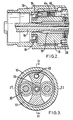
- Figure 1 is a longitudinal section of one embodiment of a two speed gearbox according to the present invention, the section being taken along line I-I of Figure 3;
- Figure 2 is a fragmentary longitudinal section of the gearbox of Figure 1 taken along line II-II of Figure 3;
- Figure 3 is a section taken along line III-III of Figure 1;
- Figure 4 is a section taken along line IV-IV of Figure 1;
- Figure 5 is a section taken along line V-V of Figure 1,
- Figure 6 shows in detail one of the apertures in the slow speed output drive of the epicyclic gear mechanism of Figure 1;
- Figure 7 shows the high speed clutch assembly of Figure 1;
- Figure 8 is a longitudinal sectional view of part of another embodiment of a two speed gearbox according to the invention; and
- Figure 9 is a longitudinal section through a control top and part of a motor assembly for use with the gearbox of Figure 8.
- Referring firstly to Figures 1-7, the gearbox shown therein has a
casing 10 formed in three parts which are screw-threadably connected together. Thecasing 10 houses anepicyclic gear mechanism 11, a highspeed clutch assembly 12, aslidable coupling 13 and anoutput shaft 14. - The
epicyclic gear mechanism 11 comprises asun gear 15 provided on ashaft 16 which serves both as an input shaft and as a high speed output drive of the gearbox, afixed ring gear 17 formed on thecasing 10, aplanet carrier 18 joumalled. for rotation inbearing 19, and twoplanet gears 20 mounted for rotation on respective planet spindles 20' in theplanet carrier 18. The planet gears 20 co-operate with thesun gear 15 and fixedring gear 17 to drive theplanet carrier 18 in the same direction of rotation as thesun gear 15 but at a much reduced speed. - The
planet carrier 18 has a tubular extension forming a hollow shaft which serves as a slowspeed output drive 21 of theepicyclic gear mechanism 11. 1 - The
output shaft 14 is joumalled for rotation inbearings output shaft 14 is generally cup-shaped and at its rearmost end it extends into theoutput drive 21 so as to act together with thebearing 19 to support theplanet carrier 18 for rotation in thecasing 10. Theoutput shaft 14 is fixed against axial movement in thecasing 10 by thebearing 22, ashoulder 24 on the output shaft, andcirclip 25. Theplanet carrier 18 is fixed against axial movement in the casing by thebearing 19 and theoutput shaft 14. - The high
speed clutch assembly 12 is accommodated within the slowspeed output drive 21 and the generally cup-shaped rear end of theoutput shaft 14. Theclutch assembly 12 comprises a drivingclutch member 26 and a drivenclutch member 27 which have mutually engageableinclined dogs clutch member 26 is fixed against axial movement by a thrust bearing 30 and acirclip 31 and is splined to theshaft 16 for rotation therewith. The drivenclutch member 27 is urged into engagement with the drivingclutch member 26 by acompression spring 32 and hasexternal splines 33 which remain in permanent engagement with theinternal splines 34 on theoutput shaft 14. The compression of the spring may be varied by ascrew 35 andpressure plate 36. - The
slidable coupling 13 is in the form of a sleeve. Threeballs 38 are held captive inrespective holes 39 in the sleeve by the driven clutch member 27 (see Figures 1 and 5). - At its rear end i.e. its end remote from the
output shaft 14, theslidable coupling 13 has three equi-angularly spacedteeth 40 which are arranged so that in the rest position of the gearbox they are positioned centrally between three equi-angularly spacedteeth 41 on the slow speed drive 21 (see in particular Figure 4). Theteeth coupling 13 relative to theslow speed drive 21 in either direction from the rest position shown in Figure 4 for a purpose which will become apparent later. - At its other end, the
coupling 13 has a fine toothedinternal spline 42 which is arranged to mate easily with a fine toothedexternal spline 43 on the rear end of theoutput shaft 14. - As shown in the drawings the
coupling 13 is in a first position in which itssplines 42 are fully disengaged from thesplines 43 on the output shaft. Thecoupling 13 is urged towards a second position in which thesplines 42 mate with thesplines 43 by aweak compression spring 44 and plunger 45 housed in the planet carrier 18 (see Figures 2 and 3). However, thecompression spring 32 is much stronger than thespring 44 and consequently in the rest position of the gearbox thecoupling 13 is held in its first position by engagement between a radial flange 46 (see Figure 7) on the drivenclutch member 27 and theballs 38 which as previously described are held captive with thecoupling 13. - As will be seen from Figures 1 and 5, the
balls 38 extend throughrespective apertures 47 in theslow speed drive 21. As will be seen more clearly from Figure 6 these apertures have two generallyhelical edges edge 50 bordering that side of the aperture adjacent to theoutput shaft 14. The purpose of theedges balls 38 lie adjacent to the adjoining ends of the twoedges - The above described gearbox may have numerous applications but it is primarily (but not exclusively) intended for use in a power tool and especially a nut runner or screwdriver.
- Experience has shown that such tools operate most efficiently if the first part of the motion is conducted at high speed and relatively low torque and the last part of the motion (when the nut, screw or the like is nearly home) at a lower speed and higher torque until the motor stalls or is switched off.
- In operation the
shaft 16 is driven by a motor, which will be housed in a rearward extension of thecasing 10, via reduction gearing. During the first part of the motion theoutput shaft 14 will be driven at the same speed as theshaft 16 andsun gear 15 by the high speedclutch assembly 12. During this time theplanet carrier 18, slowspeed output drive 21, andslidable coupling 13 will all rotate at a much lower speed determined by the number of teeth on the sun gear, planet gears and ring gear of the epicyclic gear mechanism, with theballs 38 01 theslidable coupling 13 rolling on the outer surface of the drivenclutch member 27. - When the torque applied to the
output shaft 14 exceeds a predetermined value set by the compression ofspring 32 the drivenclutch member 27 will move away from the drivingclutch member 26 under the effect of the inclined surfaces of thedogs balls 38 sufficiently to allow thespring 44 andplunger 45 to cause thecoupling 13 to move forward until the finetoothed splines 42 come into engagement with the fine toothed splines 43 on theoutput shaft 14, halting the rotation of thecoupling 13. Theslow speed drive 21 will consequently rotate relative to thecoupling 13 and one of thehelical edges aperture 47 in theslow speed drive 21 will engage itsrespective ball 38 and theballs 38, thecoupling 13 and the drivenclutch member 27 will be pushed forwards until thesplines 42 fully co-operate with thesplines 43. At this stage theteeth 40 on thecoupling 13 will come into contact with theteeth 41 on theslow speed drive 21 and the output shaft. 14 will be driven at the same speed as theplanet carrier 18 until the motor eventually stalls or is switched off or reversed. The drivenclutch member 27 is held fully disengaged from the drivingclutch member 28 by engagement between theballs 38 and theflange 46 on the driven clutch member. - If the load on the
output shaft 14 is released, then the force of thespring 32 will overcome the force applied to theballs 38 by the helical edges of theapertures 47. The drivenclutch member 27 will be pushed back into engagement with the drivingclutch member 26 and thecoupling 13 will be disengaged from theoutput shaft 14. Consequently, the gearbox will revert to a 1:1 ratio. - The gearbox described above has the additonal advantage that it will operate equally well in either direction. Indeed when used in a nut running tool it is possible to run the nut down to say about 80% of its final torque to remove all burrs, and then undo the nut by reversing the motor of the tool before running it down to its final torque. Such an operation could be achieved automatically using torque sensors and a motor control unit.
- Figure 8 shows another embodiment of the gearbox in which the
compression spring 32,screw 35 andpressure plate 36 are replaced by alocation plate 51, athrust bearing 52 and apressure plate 53. Moreover, atie rod 54 is attached to thepressure plate 53 and passes through theshaft 16. The remaining parts of the gear box of Figure 8 are identical to the gear box of Figure 1 and for ease of reference some of them are given like reference numerals. - Figure 9 shows a remote control device and part of a motor assembly for use with the gearbox of Figure 8. The motor is, as shown, a
pneumatic motor 55 having associated inlet andexhaust ports tie rod 54 extends through the centre of the motor assembly including any reduction gearing and is attached by a screw thread to apiston 58 movable in acylinder 59 in the remote control device. The length of thetie rod 54 is adjusted by the amount It Is screwed into the piston 96 such that when thepiston 58 is hard against the left hand end face of thecylinder 59, as viewed in Figure 9, theclutch members thrust bearing 30. - The
piston 58 is provided with anoperation sensing valve 60 and the remote control device has threeports cylinder 59. - The remote control device can be operated in anyone of four different modes which will be described below.
- Compressed air is supplied to port 61 of the
cylinder 59, via a pressure regulating valve (not shown), this valve being adjusted to cause thepiston 58 to be held in the retracted position shown, closing theoperation sensing valve 60. - With the gearbox in operation, applying a load of sufficient torque to the
output shaft 14, will cause the drivenclutch member 27 to be moved away from the drivingclutch member 26. Thepressure plate 53 will move with the drivenclutch member 27 and will pull thetie rod 54 and thepiston 58 forward. - The torque at the
output shaft 14 to cause this will be controlled by the pressure applied to port 61 of thecylinder 59. - It should be noted that the
piston 58, thetie rod 54, and thepressure plate 53, do not rotate, whereas theclutch assembly 12 rotates in either a LH or RH direction. To cater for this thethrust bearing 52 has been fitted. - This mode of operation is similar to (1) above but with the following additions.
- The regulated air supply at
port 61 is also supplied to port 63 of thecylinder 59. When thepiston 58 is pulled forward, theoperation sensing valve 60 is opened. This will allow the air present atport 63 to flow into the rear chamber of thecylinder 59. At this point an air signal will be present atport 62; this will indicate that a gear change has occured. If this signal is not required, then port 62 is plugged. - To reset back into high speed the torque at the
output shaft 14 has to be reduced sufficiently, and the pressure atport 63 cut and exhausted. This will allow the pressure atport 61 to return thepiston 58 to its home position, engaging the high speed ratio. - Air is supplied to port 61 at a sufficient pressure to prevent the
clutch members port 63, this pressure being prevented from entering thecylinder 59, as theoperation sensing valve 60 is closed. With the gearbox in operation, the application of a load to theoutput shaft 14 will not cause theclutch members piston 58 is too high. Sufficient load applied to theoutput shaft 14 will cause the motor to stall in the high speed gear. - There are two methods by which the unit can be signalled to change gear:
- (a) by momentarily cutting the signal at
port 61. - (b) by momentarily applying a pressure signal to
port 62. - Both of these methods allow the
piston 58 to move forward sufficiently, to allow theoperation sensing valve 60 to open. This will allow the air atport 63, to enter the rear chamber ofcylinder 59, and to act on the rear face of thepiston 58, thereby reducing the pull of thepiston 58 sufficiently to allow the high speed clutch 12 to initiate a gear change. - Method (a) will allow for a signal to be received from
port 62, to indicate a gear change. - Reducing the torque at the
output shaft 14 sufficiently will allow thepiston 58 to return to its home position, changing the unit back into the high speed ratio. In the home position the piston will be reset to be under the influence of the high pressure atport 61 only. - High pressure is applied to
port 61 as in the previous mode - With pressure on the unit is held in the high speed ratio.
- With pressure off the unit is held in the low speed ratio.
- It is to be understood that the nut running tools described above do not have to be driven by a pneumatic motor as any other suitable motor may be substituted therefor.
- It is also to be understood that instead of the
epicyclic gear mechanism 11 any other appropriate reduction gear mechanism having a high speed low torque output drive and a low speed high torque output drive could be employed. - Moreover, the gearbox could be re-arranged so that it is the driving rather than the driven clutch member which is axially movable whilst the driven clutch member is effectively fixed axially. In one embodiment of this alternative arrangement, the slidable coupling will be rotatable with the output shaft rather than with the low speed output drive. The rear hollow end of the output shaft will be lengthened and the low speed output drive shortened as compared with the embodiments described above and the helically edged apertures will be arranged in the rear hollow end of the output shaft. The slidable coupling will be capable of limited angular movement relative to the output shaft and the slidable coupling and low speed output drive will have mutually engageable splines. The driving clutch member will be urged towards the driven clutch member by a strong compression spring, fluid pressure operated device or the like and a weak spring urging the slidable coupling towards the low speed output drive will be mounted relative to the output shaft.
Claims (10)
Applications Claiming Priority (4)
| Application Number | Priority Date | Filing Date | Title |
|---|---|---|---|
| GB8530107 | 1985-12-06 | ||
| GB858530107A GB8530107D0 (en) | 1985-12-06 | 1985-12-06 | Two speed gearbox |
| GB8600687 | 1986-01-13 | ||
| GB868600687A GB8600687D0 (en) | 1985-12-06 | 1986-01-13 | Two speed gearbox |
Publications (3)
| Publication Number | Publication Date |
|---|---|
| EP0226426A2 EP0226426A2 (en) | 1987-06-24 |
| EP0226426A3 EP0226426A3 (en) | 1987-09-02 |
| EP0226426B1 true EP0226426B1 (en) | 1990-05-16 |
Family
ID=26290080
Family Applications (1)
| Application Number | Title | Priority Date | Filing Date |
|---|---|---|---|
| EP86309544A Expired EP0226426B1 (en) | 1985-12-06 | 1986-12-08 | Two speed gearbox |
Country Status (3)
| Country | Link |
|---|---|
| US (1) | US4729260A (en) |
| EP (1) | EP0226426B1 (en) |
| DE (1) | DE3671185D1 (en) |
Families Citing this family (505)
| Publication number | Priority date | Publication date | Assignee | Title |
|---|---|---|---|---|
| US5012878A (en) * | 1987-11-26 | 1991-05-07 | The Robbins Company | Rock boring machine drive head with up and down drilling capability |
| SE464747B (en) * | 1990-02-23 | 1991-06-10 | Atlas Copco Tools Ab | TWO SPEED POWER TRANSMISSION FOR A MOTOR POWER TOOL |
| DE4117150A1 (en) * | 1991-05-25 | 1992-11-26 | Ketterer Soehne Gmbh & Co Kg B | Gearbox for drive opening umbrella or awning - changes gear ratio automatically when torque exceeds defined limit |
| US5584125A (en) * | 1995-06-06 | 1996-12-17 | Mine Safety Appliances Company | Respirator mask sizing guide |
| US5992243A (en) * | 1996-12-21 | 1999-11-30 | Dana Corporation | Four-wheel drive transfer case with torque sensing |
| DE19717466B4 (en) * | 1997-04-25 | 2005-09-08 | Robert Bosch Gmbh | Multi-speed gearbox for power tools |
| US6093128A (en) * | 1999-03-12 | 2000-07-25 | Ingersoll-Rand Company | Ratchet wrench having self-shifting transmission apparatus |
| US6165096A (en) * | 1999-03-12 | 2000-12-26 | Ingersoll-Rand Company | Self-shifting transmission apparatus |
| GB0005897D0 (en) * | 2000-03-10 | 2000-05-03 | Black & Decker Inc | Power tool |
| KR100545408B1 (en) * | 2000-10-18 | 2006-01-24 | 마크스 가부시기가이샤 | Air impact driver |
| US6427735B1 (en) | 2001-02-26 | 2002-08-06 | One World Technologies, Inc. | Multi-speed surface planer and method of manufacture thereof |
| DE10222107B3 (en) * | 2002-05-17 | 2004-01-22 | Weiss, Wolfgang | Screw-nut arrangement with integrated, immediately acting protection against unintentional release of a screw connection formed therewith |
| US9060770B2 (en) | 2003-05-20 | 2015-06-23 | Ethicon Endo-Surgery, Inc. | Robotically-driven surgical instrument with E-beam driver |
| US20070084897A1 (en) | 2003-05-20 | 2007-04-19 | Shelton Frederick E Iv | Articulating surgical stapling instrument incorporating a two-piece e-beam firing mechanism |
| US11896225B2 (en) | 2004-07-28 | 2024-02-13 | Cilag Gmbh International | Staple cartridge comprising a pan |
| US8215531B2 (en) | 2004-07-28 | 2012-07-10 | Ethicon Endo-Surgery, Inc. | Surgical stapling instrument having a medical substance dispenser |
| US7250057B2 (en) * | 2005-04-11 | 2007-07-31 | St. Jude Medical Puerto Rico B.V. | Tissue puncture closure device with automatic torque sensing tamping system |
| US7988706B2 (en) | 2005-04-11 | 2011-08-02 | St. Jude Medical Puerto Rico Llc | Tissue puncture closure device with automatic torque sensing tamping system |
| US11246590B2 (en) | 2005-08-31 | 2022-02-15 | Cilag Gmbh International | Staple cartridge including staple drivers having different unfired heights |
| US8800838B2 (en) | 2005-08-31 | 2014-08-12 | Ethicon Endo-Surgery, Inc. | Robotically-controlled cable-based surgical end effectors |
| US9237891B2 (en) | 2005-08-31 | 2016-01-19 | Ethicon Endo-Surgery, Inc. | Robotically-controlled surgical stapling devices that produce formed staples having different lengths |
| US7673781B2 (en) | 2005-08-31 | 2010-03-09 | Ethicon Endo-Surgery, Inc. | Surgical stapling device with staple driver that supports multiple wire diameter staples |
| US7669746B2 (en) | 2005-08-31 | 2010-03-02 | Ethicon Endo-Surgery, Inc. | Staple cartridges for forming staples having differing formed staple heights |
| US10159482B2 (en) | 2005-08-31 | 2018-12-25 | Ethicon Llc | Fastener cartridge assembly comprising a fixed anvil and different staple heights |
| US11484312B2 (en) | 2005-08-31 | 2022-11-01 | Cilag Gmbh International | Staple cartridge comprising a staple driver arrangement |
| US7934630B2 (en) | 2005-08-31 | 2011-05-03 | Ethicon Endo-Surgery, Inc. | Staple cartridges for forming staples having differing formed staple heights |
| US20070106317A1 (en) | 2005-11-09 | 2007-05-10 | Shelton Frederick E Iv | Hydraulically and electrically actuated articulation joints for surgical instruments |
| US7464849B2 (en) * | 2006-01-31 | 2008-12-16 | Ethicon Endo-Surgery, Inc. | Electro-mechanical surgical instrument with closure system and anvil alignment components |
| US7845537B2 (en) | 2006-01-31 | 2010-12-07 | Ethicon Endo-Surgery, Inc. | Surgical instrument having recording capabilities |
| US8161977B2 (en) | 2006-01-31 | 2012-04-24 | Ethicon Endo-Surgery, Inc. | Accessing data stored in a memory of a surgical instrument |
| US11278279B2 (en) | 2006-01-31 | 2022-03-22 | Cilag Gmbh International | Surgical instrument assembly |
| US11224427B2 (en) | 2006-01-31 | 2022-01-18 | Cilag Gmbh International | Surgical stapling system including a console and retraction assembly |
| US20110290856A1 (en) | 2006-01-31 | 2011-12-01 | Ethicon Endo-Surgery, Inc. | Robotically-controlled surgical instrument with force-feedback capabilities |
| US8763879B2 (en) | 2006-01-31 | 2014-07-01 | Ethicon Endo-Surgery, Inc. | Accessing data stored in a memory of surgical instrument |
| US7422139B2 (en) * | 2006-01-31 | 2008-09-09 | Ethicon Endo-Surgery, Inc. | Motor-driven surgical cutting fastening instrument with tactile position feedback |
| US7753904B2 (en) * | 2006-01-31 | 2010-07-13 | Ethicon Endo-Surgery, Inc. | Endoscopic surgical instrument with a handle that can articulate with respect to the shaft |
| US11793518B2 (en) | 2006-01-31 | 2023-10-24 | Cilag Gmbh International | Powered surgical instruments with firing system lockout arrangements |
| US7568603B2 (en) * | 2006-01-31 | 2009-08-04 | Ethicon Endo-Surgery, Inc. | Motor-driven surgical cutting and fastening instrument with articulatable end effector |
| US8820603B2 (en) | 2006-01-31 | 2014-09-02 | Ethicon Endo-Surgery, Inc. | Accessing data stored in a memory of a surgical instrument |
| US20110024477A1 (en) | 2009-02-06 | 2011-02-03 | Hall Steven G | Driven Surgical Stapler Improvements |
| US9861359B2 (en) | 2006-01-31 | 2018-01-09 | Ethicon Llc | Powered surgical instruments with firing system lockout arrangements |
| US7575144B2 (en) | 2006-01-31 | 2009-08-18 | Ethicon Endo-Surgery, Inc. | Surgical fastener and cutter with single cable actuator |
| US8186555B2 (en) | 2006-01-31 | 2012-05-29 | Ethicon Endo-Surgery, Inc. | Motor-driven surgical cutting and fastening instrument with mechanical closure system |
| US20120292367A1 (en) | 2006-01-31 | 2012-11-22 | Ethicon Endo-Surgery, Inc. | Robotically-controlled end effector |
| US7766210B2 (en) | 2006-01-31 | 2010-08-03 | Ethicon Endo-Surgery, Inc. | Motor-driven surgical cutting and fastening instrument with user feedback system |
| US20070175951A1 (en) * | 2006-01-31 | 2007-08-02 | Shelton Frederick E Iv | Gearing selector for a powered surgical cutting and fastening instrument |
| US8708213B2 (en) | 2006-01-31 | 2014-04-29 | Ethicon Endo-Surgery, Inc. | Surgical instrument having a feedback system |
| US7770775B2 (en) | 2006-01-31 | 2010-08-10 | Ethicon Endo-Surgery, Inc. | Motor-driven surgical cutting and fastening instrument with adaptive user feedback |
| US7644848B2 (en) | 2006-01-31 | 2010-01-12 | Ethicon Endo-Surgery, Inc. | Electronic lockouts and surgical instrument including same |
| US7464846B2 (en) * | 2006-01-31 | 2008-12-16 | Ethicon Endo-Surgery, Inc. | Surgical instrument having a removable battery |
| US20110006101A1 (en) | 2009-02-06 | 2011-01-13 | EthiconEndo-Surgery, Inc. | Motor driven surgical fastener device with cutting member lockout arrangements |
| US8721630B2 (en) | 2006-03-23 | 2014-05-13 | Ethicon Endo-Surgery, Inc. | Methods and devices for controlling articulation |
| US8236010B2 (en) | 2006-03-23 | 2012-08-07 | Ethicon Endo-Surgery, Inc. | Surgical fastener and cutter with mimicking end effector |
| US8992422B2 (en) | 2006-03-23 | 2015-03-31 | Ethicon Endo-Surgery, Inc. | Robotically-controlled endoscopic accessory channel |
| US8322455B2 (en) | 2006-06-27 | 2012-12-04 | Ethicon Endo-Surgery, Inc. | Manually driven surgical cutting and fastening instrument |
| US10568652B2 (en) | 2006-09-29 | 2020-02-25 | Ethicon Llc | Surgical staples having attached drivers of different heights and stapling instruments for deploying the same |
| US10130359B2 (en) | 2006-09-29 | 2018-11-20 | Ethicon Llc | Method for forming a staple |
| US8348131B2 (en) | 2006-09-29 | 2013-01-08 | Ethicon Endo-Surgery, Inc. | Surgical stapling instrument with mechanical indicator to show levels of tissue compression |
| US11291441B2 (en) | 2007-01-10 | 2022-04-05 | Cilag Gmbh International | Surgical instrument with wireless communication between control unit and remote sensor |
| US8652120B2 (en) | 2007-01-10 | 2014-02-18 | Ethicon Endo-Surgery, Inc. | Surgical instrument with wireless communication between control unit and sensor transponders |
| US8459520B2 (en) | 2007-01-10 | 2013-06-11 | Ethicon Endo-Surgery, Inc. | Surgical instrument with wireless communication between control unit and remote sensor |
| US8684253B2 (en) | 2007-01-10 | 2014-04-01 | Ethicon Endo-Surgery, Inc. | Surgical instrument with wireless communication between a control unit of a robotic system and remote sensor |
| US8540128B2 (en) | 2007-01-11 | 2013-09-24 | Ethicon Endo-Surgery, Inc. | Surgical stapling device with a curved end effector |
| US11039836B2 (en) | 2007-01-11 | 2021-06-22 | Cilag Gmbh International | Staple cartridge for use with a surgical stapling instrument |
| US7438209B1 (en) | 2007-03-15 | 2008-10-21 | Ethicon Endo-Surgery, Inc. | Surgical stapling instruments having a releasable staple-forming pocket |
| US8893946B2 (en) | 2007-03-28 | 2014-11-25 | Ethicon Endo-Surgery, Inc. | Laparoscopic tissue thickness and clamp load measuring devices |
| WO2008138037A1 (en) * | 2007-05-09 | 2008-11-20 | Demain Technology Pty Ltd | A housing for a gearbox of a device and method |
| US8534528B2 (en) | 2007-06-04 | 2013-09-17 | Ethicon Endo-Surgery, Inc. | Surgical instrument having a multiple rate directional switching mechanism |
| US7905380B2 (en) | 2007-06-04 | 2011-03-15 | Ethicon Endo-Surgery, Inc. | Surgical instrument having a multiple rate directional switching mechanism |
| US7832408B2 (en) | 2007-06-04 | 2010-11-16 | Ethicon Endo-Surgery, Inc. | Surgical instrument having a directional switching mechanism |
| US11857181B2 (en) | 2007-06-04 | 2024-01-02 | Cilag Gmbh International | Robotically-controlled shaft based rotary drive systems for surgical instruments |
| US8931682B2 (en) | 2007-06-04 | 2015-01-13 | Ethicon Endo-Surgery, Inc. | Robotically-controlled shaft based rotary drive systems for surgical instruments |
| US8408439B2 (en) | 2007-06-22 | 2013-04-02 | Ethicon Endo-Surgery, Inc. | Surgical stapling instrument with an articulatable end effector |
| US7753245B2 (en) | 2007-06-22 | 2010-07-13 | Ethicon Endo-Surgery, Inc. | Surgical stapling instruments |
| US11849941B2 (en) | 2007-06-29 | 2023-12-26 | Cilag Gmbh International | Staple cartridge having staple cavities extending at a transverse angle relative to a longitudinal cartridge axis |
| US8561870B2 (en) | 2008-02-13 | 2013-10-22 | Ethicon Endo-Surgery, Inc. | Surgical stapling instrument |
| US7866527B2 (en) | 2008-02-14 | 2011-01-11 | Ethicon Endo-Surgery, Inc. | Surgical stapling apparatus with interlockable firing system |
| RU2493788C2 (en) | 2008-02-14 | 2013-09-27 | Этикон Эндо-Серджери, Инк. | Surgical cutting and fixing instrument, which has radio-frequency electrodes |
| US7793812B2 (en) | 2008-02-14 | 2010-09-14 | Ethicon Endo-Surgery, Inc. | Disposable motor-driven loading unit for use with a surgical cutting and stapling apparatus |
| US8758391B2 (en) | 2008-02-14 | 2014-06-24 | Ethicon Endo-Surgery, Inc. | Interchangeable tools for surgical instruments |
| US8752749B2 (en) | 2008-02-14 | 2014-06-17 | Ethicon Endo-Surgery, Inc. | Robotically-controlled disposable motor-driven loading unit |
| US9179912B2 (en) | 2008-02-14 | 2015-11-10 | Ethicon Endo-Surgery, Inc. | Robotically-controlled motorized surgical cutting and fastening instrument |
| US8584919B2 (en) | 2008-02-14 | 2013-11-19 | Ethicon Endo-Sugery, Inc. | Surgical stapling apparatus with load-sensitive firing mechanism |
| US7819298B2 (en) | 2008-02-14 | 2010-10-26 | Ethicon Endo-Surgery, Inc. | Surgical stapling apparatus with control features operable with one hand |
| US8636736B2 (en) | 2008-02-14 | 2014-01-28 | Ethicon Endo-Surgery, Inc. | Motorized surgical cutting and fastening instrument |
| US8573465B2 (en) | 2008-02-14 | 2013-11-05 | Ethicon Endo-Surgery, Inc. | Robotically-controlled surgical end effector system with rotary actuated closure systems |
| US8622274B2 (en) | 2008-02-14 | 2014-01-07 | Ethicon Endo-Surgery, Inc. | Motorized cutting and fastening instrument having control circuit for optimizing battery usage |
| US8657174B2 (en) | 2008-02-14 | 2014-02-25 | Ethicon Endo-Surgery, Inc. | Motorized surgical cutting and fastening instrument having handle based power source |
| US8459525B2 (en) | 2008-02-14 | 2013-06-11 | Ethicon Endo-Sugery, Inc. | Motorized surgical cutting and fastening instrument having a magnetic drive train torque limiting device |
| US10390823B2 (en) | 2008-02-15 | 2019-08-27 | Ethicon Llc | End effector comprising an adjunct |
| US11272927B2 (en) | 2008-02-15 | 2022-03-15 | Cilag Gmbh International | Layer arrangements for surgical staple cartridges |
| US7857186B2 (en) | 2008-09-19 | 2010-12-28 | Ethicon Endo-Surgery, Inc. | Surgical stapler having an intermediate closing position |
| PL3476312T3 (en) | 2008-09-19 | 2024-03-11 | Ethicon Llc | Surgical stapler with apparatus for adjusting staple height |
| US11648005B2 (en) | 2008-09-23 | 2023-05-16 | Cilag Gmbh International | Robotically-controlled motorized surgical instrument with an end effector |
| US9386983B2 (en) | 2008-09-23 | 2016-07-12 | Ethicon Endo-Surgery, Llc | Robotically-controlled motorized surgical instrument |
| US9050083B2 (en) | 2008-09-23 | 2015-06-09 | Ethicon Endo-Surgery, Inc. | Motorized surgical instrument |
| US8210411B2 (en) | 2008-09-23 | 2012-07-03 | Ethicon Endo-Surgery, Inc. | Motor-driven surgical cutting instrument |
| US9005230B2 (en) | 2008-09-23 | 2015-04-14 | Ethicon Endo-Surgery, Inc. | Motorized surgical instrument |
| US8608045B2 (en) | 2008-10-10 | 2013-12-17 | Ethicon Endo-Sugery, Inc. | Powered surgical cutting and stapling apparatus with manually retractable firing system |
| US8414577B2 (en) | 2009-02-05 | 2013-04-09 | Ethicon Endo-Surgery, Inc. | Surgical instruments and components for use in sterile environments |
| US8517239B2 (en) | 2009-02-05 | 2013-08-27 | Ethicon Endo-Surgery, Inc. | Surgical stapling instrument comprising a magnetic element driver |
| US8397971B2 (en) | 2009-02-05 | 2013-03-19 | Ethicon Endo-Surgery, Inc. | Sterilizable surgical instrument |
| BRPI1008667A2 (en) | 2009-02-06 | 2016-03-08 | Ethicom Endo Surgery Inc | improvement of the operated surgical stapler |
| US8444036B2 (en) | 2009-02-06 | 2013-05-21 | Ethicon Endo-Surgery, Inc. | Motor driven surgical fastener device with mechanisms for adjusting a tissue gap within the end effector |
| US8851354B2 (en) | 2009-12-24 | 2014-10-07 | Ethicon Endo-Surgery, Inc. | Surgical cutting instrument that analyzes tissue thickness |
| US8220688B2 (en) | 2009-12-24 | 2012-07-17 | Ethicon Endo-Surgery, Inc. | Motor-driven surgical cutting instrument with electric actuator directional control assembly |
| US8783543B2 (en) | 2010-07-30 | 2014-07-22 | Ethicon Endo-Surgery, Inc. | Tissue acquisition arrangements and methods for surgical stapling devices |
| US9877720B2 (en) | 2010-09-24 | 2018-01-30 | Ethicon Llc | Control features for articulating surgical device |
| US9414838B2 (en) | 2012-03-28 | 2016-08-16 | Ethicon Endo-Surgery, Llc | Tissue thickness compensator comprised of a plurality of materials |
| US11298125B2 (en) | 2010-09-30 | 2022-04-12 | Cilag Gmbh International | Tissue stapler having a thickness compensator |
| US8893949B2 (en) | 2010-09-30 | 2014-11-25 | Ethicon Endo-Surgery, Inc. | Surgical stapler with floating anvil |
| US8740038B2 (en) | 2010-09-30 | 2014-06-03 | Ethicon Endo-Surgery, Inc. | Staple cartridge comprising a releasable portion |
| US9307989B2 (en) | 2012-03-28 | 2016-04-12 | Ethicon Endo-Surgery, Llc | Tissue stapler having a thickness compensator incorportating a hydrophobic agent |
| US9241714B2 (en) | 2011-04-29 | 2016-01-26 | Ethicon Endo-Surgery, Inc. | Tissue thickness compensator and method for making the same |
| US9314246B2 (en) | 2010-09-30 | 2016-04-19 | Ethicon Endo-Surgery, Llc | Tissue stapler having a thickness compensator incorporating an anti-inflammatory agent |
| US9364233B2 (en) | 2010-09-30 | 2016-06-14 | Ethicon Endo-Surgery, Llc | Tissue thickness compensators for circular surgical staplers |
| US9566061B2 (en) | 2010-09-30 | 2017-02-14 | Ethicon Endo-Surgery, Llc | Fastener cartridge comprising a releasably attached tissue thickness compensator |
| AU2011308701B2 (en) | 2010-09-30 | 2013-11-14 | Ethicon Endo-Surgery, Inc. | Fastener system comprising a retention matrix and an alignment matrix |
| US9517063B2 (en) | 2012-03-28 | 2016-12-13 | Ethicon Endo-Surgery, Llc | Movable member for use with a tissue thickness compensator |
| US9332974B2 (en) | 2010-09-30 | 2016-05-10 | Ethicon Endo-Surgery, Llc | Layered tissue thickness compensator |
| US10945731B2 (en) | 2010-09-30 | 2021-03-16 | Ethicon Llc | Tissue thickness compensator comprising controlled release and expansion |
| US9301753B2 (en) | 2010-09-30 | 2016-04-05 | Ethicon Endo-Surgery, Llc | Expandable tissue thickness compensator |
| US9629814B2 (en) | 2010-09-30 | 2017-04-25 | Ethicon Endo-Surgery, Llc | Tissue thickness compensator configured to redistribute compressive forces |
| US9386988B2 (en) | 2010-09-30 | 2016-07-12 | Ethicon End-Surgery, LLC | Retainer assembly including a tissue thickness compensator |
| US11812965B2 (en) | 2010-09-30 | 2023-11-14 | Cilag Gmbh International | Layer of material for a surgical end effector |
| US9216019B2 (en) | 2011-09-23 | 2015-12-22 | Ethicon Endo-Surgery, Inc. | Surgical stapler with stationary staple drivers |
| US11925354B2 (en) | 2010-09-30 | 2024-03-12 | Cilag Gmbh International | Staple cartridge comprising staples positioned within a compressible portion thereof |
| US10123798B2 (en) | 2010-09-30 | 2018-11-13 | Ethicon Llc | Tissue thickness compensator comprising controlled release and expansion |
| US9220501B2 (en) | 2010-09-30 | 2015-12-29 | Ethicon Endo-Surgery, Inc. | Tissue thickness compensators |
| US8695866B2 (en) | 2010-10-01 | 2014-04-15 | Ethicon Endo-Surgery, Inc. | Surgical instrument having a power control circuit |
| AU2012250197B2 (en) | 2011-04-29 | 2017-08-10 | Ethicon Endo-Surgery, Inc. | Staple cartridge comprising staples positioned within a compressible portion thereof |
| US11207064B2 (en) | 2011-05-27 | 2021-12-28 | Cilag Gmbh International | Automated end effector component reloading system for use with a robotic system |
| US9072535B2 (en) | 2011-05-27 | 2015-07-07 | Ethicon Endo-Surgery, Inc. | Surgical stapling instruments with rotatable staple deployment arrangements |
| US9050084B2 (en) | 2011-09-23 | 2015-06-09 | Ethicon Endo-Surgery, Inc. | Staple cartridge including collapsible deck arrangement |
| US9044230B2 (en) | 2012-02-13 | 2015-06-02 | Ethicon Endo-Surgery, Inc. | Surgical cutting and fastening instrument with apparatus for determining cartridge and firing motion status |
| MX353040B (en) | 2012-03-28 | 2017-12-18 | Ethicon Endo Surgery Inc | Retainer assembly including a tissue thickness compensator. |
| US9198662B2 (en) | 2012-03-28 | 2015-12-01 | Ethicon Endo-Surgery, Inc. | Tissue thickness compensator having improved visibility |
| BR112014024102B1 (en) | 2012-03-28 | 2022-03-03 | Ethicon Endo-Surgery, Inc | CLAMP CARTRIDGE ASSEMBLY FOR A SURGICAL INSTRUMENT AND END ACTUATOR ASSEMBLY FOR A SURGICAL INSTRUMENT |
| JP6105041B2 (en) | 2012-03-28 | 2017-03-29 | エシコン・エンド−サージェリィ・インコーポレイテッドEthicon Endo−Surgery,Inc. | Tissue thickness compensator containing capsules defining a low pressure environment |
| US9101358B2 (en) | 2012-06-15 | 2015-08-11 | Ethicon Endo-Surgery, Inc. | Articulatable surgical instrument comprising a firing drive |
| US9204879B2 (en) | 2012-06-28 | 2015-12-08 | Ethicon Endo-Surgery, Inc. | Flexible drive member |
| EP2866686A1 (en) | 2012-06-28 | 2015-05-06 | Ethicon Endo-Surgery, Inc. | Empty clip cartridge lockout |
| US9289256B2 (en) | 2012-06-28 | 2016-03-22 | Ethicon Endo-Surgery, Llc | Surgical end effectors having angled tissue-contacting surfaces |
| US9649111B2 (en) | 2012-06-28 | 2017-05-16 | Ethicon Endo-Surgery, Llc | Replaceable clip cartridge for a clip applier |
| US9101385B2 (en) | 2012-06-28 | 2015-08-11 | Ethicon Endo-Surgery, Inc. | Electrode connections for rotary driven surgical tools |
| US8747238B2 (en) | 2012-06-28 | 2014-06-10 | Ethicon Endo-Surgery, Inc. | Rotary drive shaft assemblies for surgical instruments with articulatable end effectors |
| US9125662B2 (en) | 2012-06-28 | 2015-09-08 | Ethicon Endo-Surgery, Inc. | Multi-axis articulating and rotating surgical tools |
| BR112014032776B1 (en) | 2012-06-28 | 2021-09-08 | Ethicon Endo-Surgery, Inc | SURGICAL INSTRUMENT SYSTEM AND SURGICAL KIT FOR USE WITH A SURGICAL INSTRUMENT SYSTEM |
| US20140001234A1 (en) | 2012-06-28 | 2014-01-02 | Ethicon Endo-Surgery, Inc. | Coupling arrangements for attaching surgical end effectors to drive systems therefor |
| US9119657B2 (en) | 2012-06-28 | 2015-09-01 | Ethicon Endo-Surgery, Inc. | Rotary actuatable closure arrangement for surgical end effector |
| US20140001231A1 (en) | 2012-06-28 | 2014-01-02 | Ethicon Endo-Surgery, Inc. | Firing system lockout arrangements for surgical instruments |
| US9072536B2 (en) | 2012-06-28 | 2015-07-07 | Ethicon Endo-Surgery, Inc. | Differential locking arrangements for rotary powered surgical instruments |
| US9028494B2 (en) | 2012-06-28 | 2015-05-12 | Ethicon Endo-Surgery, Inc. | Interchangeable end effector coupling arrangement |
| US11202631B2 (en) | 2012-06-28 | 2021-12-21 | Cilag Gmbh International | Stapling assembly comprising a firing lockout |
| US9561038B2 (en) | 2012-06-28 | 2017-02-07 | Ethicon Endo-Surgery, Llc | Interchangeable clip applier |
| CN103862418B (en) * | 2012-12-14 | 2016-08-03 | 南京德朔实业有限公司 | Electric wrench |
| US9386984B2 (en) | 2013-02-08 | 2016-07-12 | Ethicon Endo-Surgery, Llc | Staple cartridge comprising a releasable cover |
| US10092292B2 (en) | 2013-02-28 | 2018-10-09 | Ethicon Llc | Staple forming features for surgical stapling instrument |
| BR112015021098B1 (en) | 2013-03-01 | 2022-02-15 | Ethicon Endo-Surgery, Inc | COVERAGE FOR A JOINT JOINT AND SURGICAL INSTRUMENT |
| US9307986B2 (en) | 2013-03-01 | 2016-04-12 | Ethicon Endo-Surgery, Llc | Surgical instrument soft stop |
| MX364729B (en) | 2013-03-01 | 2019-05-06 | Ethicon Endo Surgery Inc | Surgical instrument with a soft stop. |
| US20140263552A1 (en) | 2013-03-13 | 2014-09-18 | Ethicon Endo-Surgery, Inc. | Staple cartridge tissue thickness sensor system |
| US9629629B2 (en) | 2013-03-14 | 2017-04-25 | Ethicon Endo-Surgey, LLC | Control systems for surgical instruments |
| US9888919B2 (en) | 2013-03-14 | 2018-02-13 | Ethicon Llc | Method and system for operating a surgical instrument |
| US9795384B2 (en) | 2013-03-27 | 2017-10-24 | Ethicon Llc | Fastener cartridge comprising a tissue thickness compensator and a gap setting element |
| US9572577B2 (en) | 2013-03-27 | 2017-02-21 | Ethicon Endo-Surgery, Llc | Fastener cartridge comprising a tissue thickness compensator including openings therein |
| US9332984B2 (en) | 2013-03-27 | 2016-05-10 | Ethicon Endo-Surgery, Llc | Fastener cartridge assemblies |
| US9867612B2 (en) | 2013-04-16 | 2018-01-16 | Ethicon Llc | Powered surgical stapler |
| BR112015026109B1 (en) | 2013-04-16 | 2022-02-22 | Ethicon Endo-Surgery, Inc | surgical instrument |
| US9574644B2 (en) | 2013-05-30 | 2017-02-21 | Ethicon Endo-Surgery, Llc | Power module for use with a surgical instrument |
| US9775609B2 (en) | 2013-08-23 | 2017-10-03 | Ethicon Llc | Tamper proof circuit for surgical instrument battery pack |
| MX369362B (en) | 2013-08-23 | 2019-11-06 | Ethicon Endo Surgery Llc | Firing member retraction devices for powered surgical instruments. |
| US9839428B2 (en) | 2013-12-23 | 2017-12-12 | Ethicon Llc | Surgical cutting and stapling instruments with independent jaw control features |
| US20150173756A1 (en) | 2013-12-23 | 2015-06-25 | Ethicon Endo-Surgery, Inc. | Surgical cutting and stapling methods |
| US20150173749A1 (en) | 2013-12-23 | 2015-06-25 | Ethicon Endo-Surgery, Inc. | Surgical staples and staple cartridges |
| US9724092B2 (en) | 2013-12-23 | 2017-08-08 | Ethicon Llc | Modular surgical instruments |
| US9962161B2 (en) | 2014-02-12 | 2018-05-08 | Ethicon Llc | Deliverable surgical instrument |
| BR112016019387B1 (en) | 2014-02-24 | 2022-11-29 | Ethicon Endo-Surgery, Llc | SURGICAL INSTRUMENT SYSTEM AND FASTENER CARTRIDGE FOR USE WITH A SURGICAL FIXING INSTRUMENT |
| US9757124B2 (en) | 2014-02-24 | 2017-09-12 | Ethicon Llc | Implantable layer assemblies |
| BR112016021943B1 (en) | 2014-03-26 | 2022-06-14 | Ethicon Endo-Surgery, Llc | SURGICAL INSTRUMENT FOR USE BY AN OPERATOR IN A SURGICAL PROCEDURE |
| US9820738B2 (en) | 2014-03-26 | 2017-11-21 | Ethicon Llc | Surgical instrument comprising interactive systems |
| US10028761B2 (en) | 2014-03-26 | 2018-07-24 | Ethicon Llc | Feedback algorithms for manual bailout systems for surgical instruments |
| US9913642B2 (en) | 2014-03-26 | 2018-03-13 | Ethicon Llc | Surgical instrument comprising a sensor system |
| US9826977B2 (en) | 2014-03-26 | 2017-11-28 | Ethicon Llc | Sterilization verification circuit |
| JP6612256B2 (en) | 2014-04-16 | 2019-11-27 | エシコン エルエルシー | Fastener cartridge with non-uniform fastener |
| US11517315B2 (en) | 2014-04-16 | 2022-12-06 | Cilag Gmbh International | Fastener cartridges including extensions having different configurations |
| US20150297225A1 (en) | 2014-04-16 | 2015-10-22 | Ethicon Endo-Surgery, Inc. | Fastener cartridges including extensions having different configurations |
| JP6636452B2 (en) | 2014-04-16 | 2020-01-29 | エシコン エルエルシーEthicon LLC | Fastener cartridge including extension having different configurations |
| JP6532889B2 (en) | 2014-04-16 | 2019-06-19 | エシコン エルエルシーEthicon LLC | Fastener cartridge assembly and staple holder cover arrangement |
| US9801628B2 (en) | 2014-09-26 | 2017-10-31 | Ethicon Llc | Surgical staple and driver arrangements for staple cartridges |
| US10045781B2 (en) | 2014-06-13 | 2018-08-14 | Ethicon Llc | Closure lockout systems for surgical instruments |
| US20160066913A1 (en) | 2014-09-05 | 2016-03-10 | Ethicon Endo-Surgery, Inc. | Local display of tissue parameter stabilization |
| BR112017004361B1 (en) | 2014-09-05 | 2023-04-11 | Ethicon Llc | ELECTRONIC SYSTEM FOR A SURGICAL INSTRUMENT |
| US11311294B2 (en) | 2014-09-05 | 2022-04-26 | Cilag Gmbh International | Powered medical device including measurement of closure state of jaws |
| US10105142B2 (en) | 2014-09-18 | 2018-10-23 | Ethicon Llc | Surgical stapler with plurality of cutting elements |
| CN107427300B (en) | 2014-09-26 | 2020-12-04 | 伊西康有限责任公司 | Surgical suture buttress and buttress material |
| US11523821B2 (en) | 2014-09-26 | 2022-12-13 | Cilag Gmbh International | Method for creating a flexible staple line |
| US10076325B2 (en) | 2014-10-13 | 2018-09-18 | Ethicon Llc | Surgical stapling apparatus comprising a tissue stop |
| US9924944B2 (en) | 2014-10-16 | 2018-03-27 | Ethicon Llc | Staple cartridge comprising an adjunct material |
| US10517594B2 (en) | 2014-10-29 | 2019-12-31 | Ethicon Llc | Cartridge assemblies for surgical staplers |
| US11141153B2 (en) | 2014-10-29 | 2021-10-12 | Cilag Gmbh International | Staple cartridges comprising driver arrangements |
| US9844376B2 (en) | 2014-11-06 | 2017-12-19 | Ethicon Llc | Staple cartridge comprising a releasable adjunct material |
| US10736636B2 (en) | 2014-12-10 | 2020-08-11 | Ethicon Llc | Articulatable surgical instrument system |
| US10245027B2 (en) | 2014-12-18 | 2019-04-02 | Ethicon Llc | Surgical instrument with an anvil that is selectively movable about a discrete non-movable axis relative to a staple cartridge |
| US9987000B2 (en) | 2014-12-18 | 2018-06-05 | Ethicon Llc | Surgical instrument assembly comprising a flexible articulation system |
| BR112017012996B1 (en) | 2014-12-18 | 2022-11-08 | Ethicon Llc | SURGICAL INSTRUMENT WITH AN ANvil WHICH IS SELECTIVELY MOVABLE ABOUT AN IMMOVABLE GEOMETRIC AXIS DIFFERENT FROM A STAPLE CARTRIDGE |
| US9844375B2 (en) | 2014-12-18 | 2017-12-19 | Ethicon Llc | Drive arrangements for articulatable surgical instruments |
| US10085748B2 (en) | 2014-12-18 | 2018-10-02 | Ethicon Llc | Locking arrangements for detachable shaft assemblies with articulatable surgical end effectors |
| US10117649B2 (en) | 2014-12-18 | 2018-11-06 | Ethicon Llc | Surgical instrument assembly comprising a lockable articulation system |
| US9844374B2 (en) | 2014-12-18 | 2017-12-19 | Ethicon Llc | Surgical instrument systems comprising an articulatable end effector and means for adjusting the firing stroke of a firing member |
| US10188385B2 (en) | 2014-12-18 | 2019-01-29 | Ethicon Llc | Surgical instrument system comprising lockable systems |
| US10180463B2 (en) | 2015-02-27 | 2019-01-15 | Ethicon Llc | Surgical apparatus configured to assess whether a performance parameter of the surgical apparatus is within an acceptable performance band |
| US10182816B2 (en) | 2015-02-27 | 2019-01-22 | Ethicon Llc | Charging system that enables emergency resolutions for charging a battery |
| US11154301B2 (en) | 2015-02-27 | 2021-10-26 | Cilag Gmbh International | Modular stapling assembly |
| US10226250B2 (en) | 2015-02-27 | 2019-03-12 | Ethicon Llc | Modular stapling assembly |
| US10441279B2 (en) | 2015-03-06 | 2019-10-15 | Ethicon Llc | Multiple level thresholds to modify operation of powered surgical instruments |
| US10052044B2 (en) | 2015-03-06 | 2018-08-21 | Ethicon Llc | Time dependent evaluation of sensor data to determine stability, creep, and viscoelastic elements of measures |
| US9895148B2 (en) | 2015-03-06 | 2018-02-20 | Ethicon Endo-Surgery, Llc | Monitoring speed control and precision incrementing of motor for powered surgical instruments |
| US9993248B2 (en) | 2015-03-06 | 2018-06-12 | Ethicon Endo-Surgery, Llc | Smart sensors with local signal processing |
| US10245033B2 (en) | 2015-03-06 | 2019-04-02 | Ethicon Llc | Surgical instrument comprising a lockable battery housing |
| US10687806B2 (en) | 2015-03-06 | 2020-06-23 | Ethicon Llc | Adaptive tissue compression techniques to adjust closure rates for multiple tissue types |
| JP2020121162A (en) | 2015-03-06 | 2020-08-13 | エシコン エルエルシーEthicon LLC | Time dependent evaluation of sensor data to determine stability element, creep element and viscoelastic element of measurement |
| US10045776B2 (en) | 2015-03-06 | 2018-08-14 | Ethicon Llc | Control techniques and sub-processor contained within modular shaft with select control processing from handle |
| US10617412B2 (en) | 2015-03-06 | 2020-04-14 | Ethicon Llc | System for detecting the mis-insertion of a staple cartridge into a surgical stapler |
| US9924961B2 (en) | 2015-03-06 | 2018-03-27 | Ethicon Endo-Surgery, Llc | Interactive feedback system for powered surgical instruments |
| US9901342B2 (en) | 2015-03-06 | 2018-02-27 | Ethicon Endo-Surgery, Llc | Signal and power communication system positioned on a rotatable shaft |
| US9808246B2 (en) | 2015-03-06 | 2017-11-07 | Ethicon Endo-Surgery, Llc | Method of operating a powered surgical instrument |
| US10390825B2 (en) | 2015-03-31 | 2019-08-27 | Ethicon Llc | Surgical instrument with progressive rotary drive systems |
| US10178992B2 (en) | 2015-06-18 | 2019-01-15 | Ethicon Llc | Push/pull articulation drive systems for articulatable surgical instruments |
| US10835249B2 (en) | 2015-08-17 | 2020-11-17 | Ethicon Llc | Implantable layers for a surgical instrument |
| US11103248B2 (en) | 2015-08-26 | 2021-08-31 | Cilag Gmbh International | Surgical staples for minimizing staple roll |
| MX2022009705A (en) | 2015-08-26 | 2022-11-07 | Ethicon Llc | Surgical staples comprising hardness variations for improved fastening of tissue. |
| CN108348233B (en) | 2015-08-26 | 2021-05-07 | 伊西康有限责任公司 | Surgical staple strip for allowing changing staple characteristics and achieving easy cartridge loading |
| MX2022006191A (en) | 2015-09-02 | 2022-06-16 | Ethicon Llc | Surgical staple configurations with camming surfaces located between portions supporting surgical staples. |
| US10314587B2 (en) | 2015-09-02 | 2019-06-11 | Ethicon Llc | Surgical staple cartridge with improved staple driver configurations |
| US10076326B2 (en) | 2015-09-23 | 2018-09-18 | Ethicon Llc | Surgical stapler having current mirror-based motor control |
| US10085751B2 (en) | 2015-09-23 | 2018-10-02 | Ethicon Llc | Surgical stapler having temperature-based motor control |
| US10363036B2 (en) | 2015-09-23 | 2019-07-30 | Ethicon Llc | Surgical stapler having force-based motor control |
| US10105139B2 (en) | 2015-09-23 | 2018-10-23 | Ethicon Llc | Surgical stapler having downstream current-based motor control |
| US10238386B2 (en) | 2015-09-23 | 2019-03-26 | Ethicon Llc | Surgical stapler having motor control based on an electrical parameter related to a motor current |
| US10327769B2 (en) | 2015-09-23 | 2019-06-25 | Ethicon Llc | Surgical stapler having motor control based on a drive system component |
| US10299878B2 (en) | 2015-09-25 | 2019-05-28 | Ethicon Llc | Implantable adjunct systems for determining adjunct skew |
| US11890015B2 (en) | 2015-09-30 | 2024-02-06 | Cilag Gmbh International | Compressible adjunct with crossing spacer fibers |
| US10980539B2 (en) | 2015-09-30 | 2021-04-20 | Ethicon Llc | Implantable adjunct comprising bonded layers |
| US10736633B2 (en) | 2015-09-30 | 2020-08-11 | Ethicon Llc | Compressible adjunct with looping members |
| US10172620B2 (en) | 2015-09-30 | 2019-01-08 | Ethicon Llc | Compressible adjuncts with bonding nodes |
| US10292704B2 (en) | 2015-12-30 | 2019-05-21 | Ethicon Llc | Mechanisms for compensating for battery pack failure in powered surgical instruments |
| US10368865B2 (en) | 2015-12-30 | 2019-08-06 | Ethicon Llc | Mechanisms for compensating for drivetrain failure in powered surgical instruments |
| US10265068B2 (en) | 2015-12-30 | 2019-04-23 | Ethicon Llc | Surgical instruments with separable motors and motor control circuits |
| US11213293B2 (en) | 2016-02-09 | 2022-01-04 | Cilag Gmbh International | Articulatable surgical instruments with single articulation link arrangements |
| CN108882932B (en) | 2016-02-09 | 2021-07-23 | 伊西康有限责任公司 | Surgical instrument with asymmetric articulation configuration |
| US10588625B2 (en) | 2016-02-09 | 2020-03-17 | Ethicon Llc | Articulatable surgical instruments with off-axis firing beam arrangements |
| US11224426B2 (en) | 2016-02-12 | 2022-01-18 | Cilag Gmbh International | Mechanisms for compensating for drivetrain failure in powered surgical instruments |
| US10258331B2 (en) | 2016-02-12 | 2019-04-16 | Ethicon Llc | Mechanisms for compensating for drivetrain failure in powered surgical instruments |
| US10448948B2 (en) | 2016-02-12 | 2019-10-22 | Ethicon Llc | Mechanisms for compensating for drivetrain failure in powered surgical instruments |
| US10617413B2 (en) | 2016-04-01 | 2020-04-14 | Ethicon Llc | Closure system arrangements for surgical cutting and stapling devices with separate and distinct firing shafts |
| US10485542B2 (en) | 2016-04-01 | 2019-11-26 | Ethicon Llc | Surgical stapling instrument comprising multiple lockouts |
| US11607239B2 (en) | 2016-04-15 | 2023-03-21 | Cilag Gmbh International | Systems and methods for controlling a surgical stapling and cutting instrument |
| US10335145B2 (en) | 2016-04-15 | 2019-07-02 | Ethicon Llc | Modular surgical instrument with configurable operating mode |
| US10492783B2 (en) | 2016-04-15 | 2019-12-03 | Ethicon, Llc | Surgical instrument with improved stop/start control during a firing motion |
| US10426467B2 (en) | 2016-04-15 | 2019-10-01 | Ethicon Llc | Surgical instrument with detection sensors |
| US10828028B2 (en) | 2016-04-15 | 2020-11-10 | Ethicon Llc | Surgical instrument with multiple program responses during a firing motion |
| US10357247B2 (en) | 2016-04-15 | 2019-07-23 | Ethicon Llc | Surgical instrument with multiple program responses during a firing motion |
| US10456137B2 (en) | 2016-04-15 | 2019-10-29 | Ethicon Llc | Staple formation detection mechanisms |
| US10405859B2 (en) | 2016-04-15 | 2019-09-10 | Ethicon Llc | Surgical instrument with adjustable stop/start control during a firing motion |
| US11179150B2 (en) | 2016-04-15 | 2021-11-23 | Cilag Gmbh International | Systems and methods for controlling a surgical stapling and cutting instrument |
| US20170296173A1 (en) | 2016-04-18 | 2017-10-19 | Ethicon Endo-Surgery, Llc | Method for operating a surgical instrument |
| US11317917B2 (en) | 2016-04-18 | 2022-05-03 | Cilag Gmbh International | Surgical stapling system comprising a lockable firing assembly |
| US10426469B2 (en) | 2016-04-18 | 2019-10-01 | Ethicon Llc | Surgical instrument comprising a primary firing lockout and a secondary firing lockout |
| USD826405S1 (en) | 2016-06-24 | 2018-08-21 | Ethicon Llc | Surgical fastener |
| CN109310431B (en) | 2016-06-24 | 2022-03-04 | 伊西康有限责任公司 | Staple cartridge comprising wire staples and punch staples |
| USD847989S1 (en) | 2016-06-24 | 2019-05-07 | Ethicon Llc | Surgical fastener cartridge |
| USD850617S1 (en) | 2016-06-24 | 2019-06-04 | Ethicon Llc | Surgical fastener cartridge |
| US10542979B2 (en) | 2016-06-24 | 2020-01-28 | Ethicon Llc | Stamped staples and staple cartridges using the same |
| US10537325B2 (en) | 2016-12-21 | 2020-01-21 | Ethicon Llc | Staple forming pocket arrangement to accommodate different types of staples |
| JP7010956B2 (en) | 2016-12-21 | 2022-01-26 | エシコン エルエルシー | How to staple tissue |
| CN110099619B (en) | 2016-12-21 | 2022-07-15 | 爱惜康有限责任公司 | Lockout device for surgical end effector and replaceable tool assembly |
| US10888322B2 (en) | 2016-12-21 | 2021-01-12 | Ethicon Llc | Surgical instrument comprising a cutting member |
| US10980536B2 (en) | 2016-12-21 | 2021-04-20 | Ethicon Llc | No-cartridge and spent cartridge lockout arrangements for surgical staplers |
| US20180168648A1 (en) | 2016-12-21 | 2018-06-21 | Ethicon Endo-Surgery, Llc | Durability features for end effectors and firing assemblies of surgical stapling instruments |
| US10542982B2 (en) | 2016-12-21 | 2020-01-28 | Ethicon Llc | Shaft assembly comprising first and second articulation lockouts |
| US10993715B2 (en) | 2016-12-21 | 2021-05-04 | Ethicon Llc | Staple cartridge comprising staples with different clamping breadths |
| US10687810B2 (en) | 2016-12-21 | 2020-06-23 | Ethicon Llc | Stepped staple cartridge with tissue retention and gap setting features |
| US10835246B2 (en) | 2016-12-21 | 2020-11-17 | Ethicon Llc | Staple cartridges and arrangements of staples and staple cavities therein |
| US10898186B2 (en) | 2016-12-21 | 2021-01-26 | Ethicon Llc | Staple forming pocket arrangements comprising primary sidewalls and pocket sidewalls |
| US10610224B2 (en) | 2016-12-21 | 2020-04-07 | Ethicon Llc | Lockout arrangements for surgical end effectors and replaceable tool assemblies |
| US20180168615A1 (en) | 2016-12-21 | 2018-06-21 | Ethicon Endo-Surgery, Llc | Method of deforming staples from two different types of staple cartridges with the same surgical stapling instrument |
| US10639034B2 (en) | 2016-12-21 | 2020-05-05 | Ethicon Llc | Surgical instruments with lockout arrangements for preventing firing system actuation unless an unspent staple cartridge is present |
| US11134942B2 (en) | 2016-12-21 | 2021-10-05 | Cilag Gmbh International | Surgical stapling instruments and staple-forming anvils |
| US11419606B2 (en) | 2016-12-21 | 2022-08-23 | Cilag Gmbh International | Shaft assembly comprising a clutch configured to adapt the output of a rotary firing member to two different systems |
| US10485543B2 (en) | 2016-12-21 | 2019-11-26 | Ethicon Llc | Anvil having a knife slot width |
| US10426471B2 (en) | 2016-12-21 | 2019-10-01 | Ethicon Llc | Surgical instrument with multiple failure response modes |
| BR112019011947A2 (en) | 2016-12-21 | 2019-10-29 | Ethicon Llc | surgical stapling systems |
| US10695055B2 (en) | 2016-12-21 | 2020-06-30 | Ethicon Llc | Firing assembly comprising a lockout |
| US10945727B2 (en) | 2016-12-21 | 2021-03-16 | Ethicon Llc | Staple cartridge with deformable driver retention features |
| US11684367B2 (en) | 2016-12-21 | 2023-06-27 | Cilag Gmbh International | Stepped assembly having and end-of-life indicator |
| US20180168618A1 (en) | 2016-12-21 | 2018-06-21 | Ethicon Endo-Surgery, Llc | Surgical stapling systems |
| US10758230B2 (en) | 2016-12-21 | 2020-09-01 | Ethicon Llc | Surgical instrument with primary and safety processors |
| USD879809S1 (en) | 2017-06-20 | 2020-03-31 | Ethicon Llc | Display panel with changeable graphical user interface |
| US10888321B2 (en) | 2017-06-20 | 2021-01-12 | Ethicon Llc | Systems and methods for controlling velocity of a displacement member of a surgical stapling and cutting instrument |
| US10813639B2 (en) | 2017-06-20 | 2020-10-27 | Ethicon Llc | Closed loop feedback control of motor velocity of a surgical stapling and cutting instrument based on system conditions |
| US11517325B2 (en) | 2017-06-20 | 2022-12-06 | Cilag Gmbh International | Closed loop feedback control of motor velocity of a surgical stapling and cutting instrument based on measured displacement distance traveled over a specified time interval |
| US10980537B2 (en) | 2017-06-20 | 2021-04-20 | Ethicon Llc | Closed loop feedback control of motor velocity of a surgical stapling and cutting instrument based on measured time over a specified number of shaft rotations |
| USD879808S1 (en) | 2017-06-20 | 2020-03-31 | Ethicon Llc | Display panel with graphical user interface |
| US10368864B2 (en) | 2017-06-20 | 2019-08-06 | Ethicon Llc | Systems and methods for controlling displaying motor velocity for a surgical instrument |
| US10779820B2 (en) | 2017-06-20 | 2020-09-22 | Ethicon Llc | Systems and methods for controlling motor speed according to user input for a surgical instrument |
| USD890784S1 (en) | 2017-06-20 | 2020-07-21 | Ethicon Llc | Display panel with changeable graphical user interface |
| US10307170B2 (en) | 2017-06-20 | 2019-06-04 | Ethicon Llc | Method for closed loop control of motor velocity of a surgical stapling and cutting instrument |
| US11090046B2 (en) | 2017-06-20 | 2021-08-17 | Cilag Gmbh International | Systems and methods for controlling displacement member motion of a surgical stapling and cutting instrument |
| US10390841B2 (en) | 2017-06-20 | 2019-08-27 | Ethicon Llc | Control of motor velocity of a surgical stapling and cutting instrument based on angle of articulation |
| US10881399B2 (en) | 2017-06-20 | 2021-01-05 | Ethicon Llc | Techniques for adaptive control of motor velocity of a surgical stapling and cutting instrument |
| US11071554B2 (en) | 2017-06-20 | 2021-07-27 | Cilag Gmbh International | Closed loop feedback control of motor velocity of a surgical stapling and cutting instrument based on magnitude of velocity error measurements |
| US10881396B2 (en) | 2017-06-20 | 2021-01-05 | Ethicon Llc | Surgical instrument with variable duration trigger arrangement |
| US11653914B2 (en) | 2017-06-20 | 2023-05-23 | Cilag Gmbh International | Systems and methods for controlling motor velocity of a surgical stapling and cutting instrument according to articulation angle of end effector |
| US10327767B2 (en) | 2017-06-20 | 2019-06-25 | Ethicon Llc | Control of motor velocity of a surgical stapling and cutting instrument based on angle of articulation |
| US11382638B2 (en) | 2017-06-20 | 2022-07-12 | Cilag Gmbh International | Closed loop feedback control of motor velocity of a surgical stapling and cutting instrument based on measured time over a specified displacement distance |
| US10624633B2 (en) | 2017-06-20 | 2020-04-21 | Ethicon Llc | Systems and methods for controlling motor velocity of a surgical stapling and cutting instrument |
| US10646220B2 (en) | 2017-06-20 | 2020-05-12 | Ethicon Llc | Systems and methods for controlling displacement member velocity for a surgical instrument |
| US10772629B2 (en) | 2017-06-27 | 2020-09-15 | Ethicon Llc | Surgical anvil arrangements |
| US11266405B2 (en) | 2017-06-27 | 2022-03-08 | Cilag Gmbh International | Surgical anvil manufacturing methods |
| US10856869B2 (en) | 2017-06-27 | 2020-12-08 | Ethicon Llc | Surgical anvil arrangements |
| US10993716B2 (en) | 2017-06-27 | 2021-05-04 | Ethicon Llc | Surgical anvil arrangements |
| US11141154B2 (en) | 2017-06-27 | 2021-10-12 | Cilag Gmbh International | Surgical end effectors and anvils |
| US11324503B2 (en) | 2017-06-27 | 2022-05-10 | Cilag Gmbh International | Surgical firing member arrangements |
| US10716614B2 (en) | 2017-06-28 | 2020-07-21 | Ethicon Llc | Surgical shaft assemblies with slip ring assemblies with increased contact pressure |
| US10903685B2 (en) | 2017-06-28 | 2021-01-26 | Ethicon Llc | Surgical shaft assemblies with slip ring assemblies forming capacitive channels |
| USD851762S1 (en) | 2017-06-28 | 2019-06-18 | Ethicon Llc | Anvil |
| US11564686B2 (en) | 2017-06-28 | 2023-01-31 | Cilag Gmbh International | Surgical shaft assemblies with flexible interfaces |
| USD854151S1 (en) | 2017-06-28 | 2019-07-16 | Ethicon Llc | Surgical instrument shaft |
| USD869655S1 (en) | 2017-06-28 | 2019-12-10 | Ethicon Llc | Surgical fastener cartridge |
| USD906355S1 (en) | 2017-06-28 | 2020-12-29 | Ethicon Llc | Display screen or portion thereof with a graphical user interface for a surgical instrument |
| US11259805B2 (en) | 2017-06-28 | 2022-03-01 | Cilag Gmbh International | Surgical instrument comprising firing member supports |
| US10765427B2 (en) | 2017-06-28 | 2020-09-08 | Ethicon Llc | Method for articulating a surgical instrument |
| US11246592B2 (en) | 2017-06-28 | 2022-02-15 | Cilag Gmbh International | Surgical instrument comprising an articulation system lockable to a frame |
| EP3420947B1 (en) | 2017-06-28 | 2022-05-25 | Cilag GmbH International | Surgical instrument comprising selectively actuatable rotatable couplers |
| US11389161B2 (en) | 2017-06-28 | 2022-07-19 | Cilag Gmbh International | Surgical instrument comprising selectively actuatable rotatable couplers |
| US10211586B2 (en) | 2017-06-28 | 2019-02-19 | Ethicon Llc | Surgical shaft assemblies with watertight housings |
| US10786253B2 (en) | 2017-06-28 | 2020-09-29 | Ethicon Llc | Surgical end effectors with improved jaw aperture arrangements |
| US10932772B2 (en) | 2017-06-29 | 2021-03-02 | Ethicon Llc | Methods for closed loop velocity control for robotic surgical instrument |
| US10258418B2 (en) | 2017-06-29 | 2019-04-16 | Ethicon Llc | System for controlling articulation forces |
| US10898183B2 (en) | 2017-06-29 | 2021-01-26 | Ethicon Llc | Robotic surgical instrument with closed loop feedback techniques for advancement of closure member during firing |
| US10398434B2 (en) | 2017-06-29 | 2019-09-03 | Ethicon Llc | Closed loop velocity control of closure member for robotic surgical instrument |
| US11007022B2 (en) | 2017-06-29 | 2021-05-18 | Ethicon Llc | Closed loop velocity control techniques based on sensed tissue parameters for robotic surgical instrument |
| US11944300B2 (en) | 2017-08-03 | 2024-04-02 | Cilag Gmbh International | Method for operating a surgical system bailout |
| US11471155B2 (en) | 2017-08-03 | 2022-10-18 | Cilag Gmbh International | Surgical system bailout |
| US11304695B2 (en) | 2017-08-03 | 2022-04-19 | Cilag Gmbh International | Surgical system shaft interconnection |
| US10796471B2 (en) | 2017-09-29 | 2020-10-06 | Ethicon Llc | Systems and methods of displaying a knife position for a surgical instrument |
| US11399829B2 (en) | 2017-09-29 | 2022-08-02 | Cilag Gmbh International | Systems and methods of initiating a power shutdown mode for a surgical instrument |
| USD917500S1 (en) | 2017-09-29 | 2021-04-27 | Ethicon Llc | Display screen or portion thereof with graphical user interface |
| USD907648S1 (en) | 2017-09-29 | 2021-01-12 | Ethicon Llc | Display screen or portion thereof with animated graphical user interface |
| US10729501B2 (en) | 2017-09-29 | 2020-08-04 | Ethicon Llc | Systems and methods for language selection of a surgical instrument |
| US10743872B2 (en) | 2017-09-29 | 2020-08-18 | Ethicon Llc | System and methods for controlling a display of a surgical instrument |
| US10765429B2 (en) | 2017-09-29 | 2020-09-08 | Ethicon Llc | Systems and methods for providing alerts according to the operational state of a surgical instrument |
| USD907647S1 (en) | 2017-09-29 | 2021-01-12 | Ethicon Llc | Display screen or portion thereof with animated graphical user interface |
| US11134944B2 (en) | 2017-10-30 | 2021-10-05 | Cilag Gmbh International | Surgical stapler knife motion controls |
| US11090075B2 (en) | 2017-10-30 | 2021-08-17 | Cilag Gmbh International | Articulation features for surgical end effector |
| US10842490B2 (en) | 2017-10-31 | 2020-11-24 | Ethicon Llc | Cartridge body design with force reduction based on firing completion |
| US10779903B2 (en) | 2017-10-31 | 2020-09-22 | Ethicon Llc | Positive shaft rotation lock activated by jaw closure |
| US11197670B2 (en) | 2017-12-15 | 2021-12-14 | Cilag Gmbh International | Surgical end effectors with pivotal jaws configured to touch at their respective distal ends when fully closed |
| US10828033B2 (en) | 2017-12-15 | 2020-11-10 | Ethicon Llc | Handheld electromechanical surgical instruments with improved motor control arrangements for positioning components of an adapter coupled thereto |
| US10869666B2 (en) | 2017-12-15 | 2020-12-22 | Ethicon Llc | Adapters with control systems for controlling multiple motors of an electromechanical surgical instrument |
| US10687813B2 (en) | 2017-12-15 | 2020-06-23 | Ethicon Llc | Adapters with firing stroke sensing arrangements for use in connection with electromechanical surgical instruments |
| US10779825B2 (en) | 2017-12-15 | 2020-09-22 | Ethicon Llc | Adapters with end effector position sensing and control arrangements for use in connection with electromechanical surgical instruments |
| US10966718B2 (en) | 2017-12-15 | 2021-04-06 | Ethicon Llc | Dynamic clamping assemblies with improved wear characteristics for use in connection with electromechanical surgical instruments |
| US10779826B2 (en) | 2017-12-15 | 2020-09-22 | Ethicon Llc | Methods of operating surgical end effectors |
| US11033267B2 (en) | 2017-12-15 | 2021-06-15 | Ethicon Llc | Systems and methods of controlling a clamping member firing rate of a surgical instrument |
| US11071543B2 (en) | 2017-12-15 | 2021-07-27 | Cilag Gmbh International | Surgical end effectors with clamping assemblies configured to increase jaw aperture ranges |
| US10743875B2 (en) | 2017-12-15 | 2020-08-18 | Ethicon Llc | Surgical end effectors with jaw stiffener arrangements configured to permit monitoring of firing member |
| US11006955B2 (en) | 2017-12-15 | 2021-05-18 | Ethicon Llc | End effectors with positive jaw opening features for use with adapters for electromechanical surgical instruments |
| US10743874B2 (en) | 2017-12-15 | 2020-08-18 | Ethicon Llc | Sealed adapters for use with electromechanical surgical instruments |
| US10729509B2 (en) | 2017-12-19 | 2020-08-04 | Ethicon Llc | Surgical instrument comprising closure and firing locking mechanism |
| USD910847S1 (en) | 2017-12-19 | 2021-02-16 | Ethicon Llc | Surgical instrument assembly |
| US10835330B2 (en) | 2017-12-19 | 2020-11-17 | Ethicon Llc | Method for determining the position of a rotatable jaw of a surgical instrument attachment assembly |
| US11045270B2 (en) | 2017-12-19 | 2021-06-29 | Cilag Gmbh International | Robotic attachment comprising exterior drive actuator |
| US10716565B2 (en) | 2017-12-19 | 2020-07-21 | Ethicon Llc | Surgical instruments with dual articulation drivers |
| US11020112B2 (en) | 2017-12-19 | 2021-06-01 | Ethicon Llc | Surgical tools configured for interchangeable use with different controller interfaces |
| US11576668B2 (en) | 2017-12-21 | 2023-02-14 | Cilag Gmbh International | Staple instrument comprising a firing path display |
| US11311290B2 (en) | 2017-12-21 | 2022-04-26 | Cilag Gmbh International | Surgical instrument comprising an end effector dampener |
| US11076853B2 (en) | 2017-12-21 | 2021-08-03 | Cilag Gmbh International | Systems and methods of displaying a knife position during transection for a surgical instrument |
| US11129680B2 (en) | 2017-12-21 | 2021-09-28 | Cilag Gmbh International | Surgical instrument comprising a projector |
| US11039834B2 (en) | 2018-08-20 | 2021-06-22 | Cilag Gmbh International | Surgical stapler anvils with staple directing protrusions and tissue stability features |
| US10779821B2 (en) | 2018-08-20 | 2020-09-22 | Ethicon Llc | Surgical stapler anvils with tissue stop features configured to avoid tissue pinch |
| USD914878S1 (en) | 2018-08-20 | 2021-03-30 | Ethicon Llc | Surgical instrument anvil |
| US10856870B2 (en) | 2018-08-20 | 2020-12-08 | Ethicon Llc | Switching arrangements for motor powered articulatable surgical instruments |
| US11083458B2 (en) | 2018-08-20 | 2021-08-10 | Cilag Gmbh International | Powered surgical instruments with clutching arrangements to convert linear drive motions to rotary drive motions |
| US10912559B2 (en) | 2018-08-20 | 2021-02-09 | Ethicon Llc | Reinforced deformable anvil tip for surgical stapler anvil |
| US11207065B2 (en) | 2018-08-20 | 2021-12-28 | Cilag Gmbh International | Method for fabricating surgical stapler anvils |
| US11291440B2 (en) | 2018-08-20 | 2022-04-05 | Cilag Gmbh International | Method for operating a powered articulatable surgical instrument |
| US11324501B2 (en) | 2018-08-20 | 2022-05-10 | Cilag Gmbh International | Surgical stapling devices with improved closure members |
| US10842492B2 (en) | 2018-08-20 | 2020-11-24 | Ethicon Llc | Powered articulatable surgical instruments with clutching and locking arrangements for linking an articulation drive system to a firing drive system |
| US11045192B2 (en) | 2018-08-20 | 2021-06-29 | Cilag Gmbh International | Fabricating techniques for surgical stapler anvils |
| US11253256B2 (en) | 2018-08-20 | 2022-02-22 | Cilag Gmbh International | Articulatable motor powered surgical instruments with dedicated articulation motor arrangements |
| US11696761B2 (en) | 2019-03-25 | 2023-07-11 | Cilag Gmbh International | Firing drive arrangements for surgical systems |
| US11172929B2 (en) | 2019-03-25 | 2021-11-16 | Cilag Gmbh International | Articulation drive arrangements for surgical systems |
| US11147551B2 (en) | 2019-03-25 | 2021-10-19 | Cilag Gmbh International | Firing drive arrangements for surgical systems |
| US11147553B2 (en) | 2019-03-25 | 2021-10-19 | Cilag Gmbh International | Firing drive arrangements for surgical systems |
| US11452528B2 (en) | 2019-04-30 | 2022-09-27 | Cilag Gmbh International | Articulation actuators for a surgical instrument |
| US11426251B2 (en) | 2019-04-30 | 2022-08-30 | Cilag Gmbh International | Articulation directional lights on a surgical instrument |
| US11648009B2 (en) | 2019-04-30 | 2023-05-16 | Cilag Gmbh International | Rotatable jaw tip for a surgical instrument |
| US11471157B2 (en) | 2019-04-30 | 2022-10-18 | Cilag Gmbh International | Articulation control mapping for a surgical instrument |
| US11903581B2 (en) | 2019-04-30 | 2024-02-20 | Cilag Gmbh International | Methods for stapling tissue using a surgical instrument |
| US11253254B2 (en) | 2019-04-30 | 2022-02-22 | Cilag Gmbh International | Shaft rotation actuator on a surgical instrument |
| US11432816B2 (en) | 2019-04-30 | 2022-09-06 | Cilag Gmbh International | Articulation pin for a surgical instrument |
| CN114007818A (en) * | 2019-06-18 | 2022-02-01 | 阿特拉斯·科普柯工业技术公司 | Power tool and torque responsive gear unit for power tool |
| US11553971B2 (en) | 2019-06-28 | 2023-01-17 | Cilag Gmbh International | Surgical RFID assemblies for display and communication |
| US11051807B2 (en) | 2019-06-28 | 2021-07-06 | Cilag Gmbh International | Packaging assembly including a particulate trap |
| US11259803B2 (en) | 2019-06-28 | 2022-03-01 | Cilag Gmbh International | Surgical stapling system having an information encryption protocol |
| US11241235B2 (en) | 2019-06-28 | 2022-02-08 | Cilag Gmbh International | Method of using multiple RFID chips with a surgical assembly |
| US11291451B2 (en) | 2019-06-28 | 2022-04-05 | Cilag Gmbh International | Surgical instrument with battery compatibility verification functionality |
| US11399837B2 (en) | 2019-06-28 | 2022-08-02 | Cilag Gmbh International | Mechanisms for motor control adjustments of a motorized surgical instrument |
| US11426167B2 (en) | 2019-06-28 | 2022-08-30 | Cilag Gmbh International | Mechanisms for proper anvil attachment surgical stapling head assembly |
| US11660163B2 (en) | 2019-06-28 | 2023-05-30 | Cilag Gmbh International | Surgical system with RFID tags for updating motor assembly parameters |
| US11771419B2 (en) | 2019-06-28 | 2023-10-03 | Cilag Gmbh International | Packaging for a replaceable component of a surgical stapling system |
| US11478241B2 (en) | 2019-06-28 | 2022-10-25 | Cilag Gmbh International | Staple cartridge including projections |
| US11219455B2 (en) | 2019-06-28 | 2022-01-11 | Cilag Gmbh International | Surgical instrument including a lockout key |
| US11497492B2 (en) | 2019-06-28 | 2022-11-15 | Cilag Gmbh International | Surgical instrument including an articulation lock |
| US11298132B2 (en) | 2019-06-28 | 2022-04-12 | Cilag GmbH Inlernational | Staple cartridge including a honeycomb extension |
| US11224497B2 (en) | 2019-06-28 | 2022-01-18 | Cilag Gmbh International | Surgical systems with multiple RFID tags |
| US11638587B2 (en) | 2019-06-28 | 2023-05-02 | Cilag Gmbh International | RFID identification systems for surgical instruments |
| US11627959B2 (en) | 2019-06-28 | 2023-04-18 | Cilag Gmbh International | Surgical instruments including manual and powered system lockouts |
| US11523822B2 (en) | 2019-06-28 | 2022-12-13 | Cilag Gmbh International | Battery pack including a circuit interrupter |
| US11464601B2 (en) | 2019-06-28 | 2022-10-11 | Cilag Gmbh International | Surgical instrument comprising an RFID system for tracking a movable component |
| US11246678B2 (en) | 2019-06-28 | 2022-02-15 | Cilag Gmbh International | Surgical stapling system having a frangible RFID tag |
| US11298127B2 (en) | 2019-06-28 | 2022-04-12 | Cilag GmbH Interational | Surgical stapling system having a lockout mechanism for an incompatible cartridge |
| US11376098B2 (en) | 2019-06-28 | 2022-07-05 | Cilag Gmbh International | Surgical instrument system comprising an RFID system |
| US11684434B2 (en) | 2019-06-28 | 2023-06-27 | Cilag Gmbh International | Surgical RFID assemblies for instrument operational setting control |
| SE543799C2 (en) * | 2019-10-31 | 2021-07-27 | Atlas Copco Ind Technique Ab | Power tool and two-speed gear assembly for a power tool |
| US11446029B2 (en) | 2019-12-19 | 2022-09-20 | Cilag Gmbh International | Staple cartridge comprising projections extending from a curved deck surface |
| US11911032B2 (en) | 2019-12-19 | 2024-02-27 | Cilag Gmbh International | Staple cartridge comprising a seating cam |
| US11607219B2 (en) | 2019-12-19 | 2023-03-21 | Cilag Gmbh International | Staple cartridge comprising a detachable tissue cutting knife |
| US11529137B2 (en) | 2019-12-19 | 2022-12-20 | Cilag Gmbh International | Staple cartridge comprising driver retention members |
| US11559304B2 (en) | 2019-12-19 | 2023-01-24 | Cilag Gmbh International | Surgical instrument comprising a rapid closure mechanism |
| US11529139B2 (en) | 2019-12-19 | 2022-12-20 | Cilag Gmbh International | Motor driven surgical instrument |
| US11931033B2 (en) | 2019-12-19 | 2024-03-19 | Cilag Gmbh International | Staple cartridge comprising a latch lockout |
| US11234698B2 (en) | 2019-12-19 | 2022-02-01 | Cilag Gmbh International | Stapling system comprising a clamp lockout and a firing lockout |
| US11464512B2 (en) | 2019-12-19 | 2022-10-11 | Cilag Gmbh International | Staple cartridge comprising a curved deck surface |
| US11844520B2 (en) | 2019-12-19 | 2023-12-19 | Cilag Gmbh International | Staple cartridge comprising driver retention members |
| US11576672B2 (en) | 2019-12-19 | 2023-02-14 | Cilag Gmbh International | Surgical instrument comprising a closure system including a closure member and an opening member driven by a drive screw |
| US11304696B2 (en) | 2019-12-19 | 2022-04-19 | Cilag Gmbh International | Surgical instrument comprising a powered articulation system |
| US11291447B2 (en) | 2019-12-19 | 2022-04-05 | Cilag Gmbh International | Stapling instrument comprising independent jaw closing and staple firing systems |
| US11701111B2 (en) | 2019-12-19 | 2023-07-18 | Cilag Gmbh International | Method for operating a surgical stapling instrument |
| US11504122B2 (en) | 2019-12-19 | 2022-11-22 | Cilag Gmbh International | Surgical instrument comprising a nested firing member |
| USD975278S1 (en) | 2020-06-02 | 2023-01-10 | Cilag Gmbh International | Staple cartridge |
| USD966512S1 (en) | 2020-06-02 | 2022-10-11 | Cilag Gmbh International | Staple cartridge |
| USD974560S1 (en) | 2020-06-02 | 2023-01-03 | Cilag Gmbh International | Staple cartridge |
| USD975850S1 (en) | 2020-06-02 | 2023-01-17 | Cilag Gmbh International | Staple cartridge |
| USD975851S1 (en) | 2020-06-02 | 2023-01-17 | Cilag Gmbh International | Staple cartridge |
| USD967421S1 (en) | 2020-06-02 | 2022-10-18 | Cilag Gmbh International | Staple cartridge |
| USD976401S1 (en) | 2020-06-02 | 2023-01-24 | Cilag Gmbh International | Staple cartridge |
| US20220031351A1 (en) | 2020-07-28 | 2022-02-03 | Cilag Gmbh International | Surgical instruments with differential articulation joint arrangements for accommodating flexible actuators |
| US11896217B2 (en) | 2020-10-29 | 2024-02-13 | Cilag Gmbh International | Surgical instrument comprising an articulation lock |
| USD1013170S1 (en) | 2020-10-29 | 2024-01-30 | Cilag Gmbh International | Surgical instrument assembly |
| US11931025B2 (en) | 2020-10-29 | 2024-03-19 | Cilag Gmbh International | Surgical instrument comprising a releasable closure drive lock |
| US11517390B2 (en) | 2020-10-29 | 2022-12-06 | Cilag Gmbh International | Surgical instrument comprising a limited travel switch |
| US11844518B2 (en) | 2020-10-29 | 2023-12-19 | Cilag Gmbh International | Method for operating a surgical instrument |
| US11617577B2 (en) | 2020-10-29 | 2023-04-04 | Cilag Gmbh International | Surgical instrument comprising a sensor configured to sense whether an articulation drive of the surgical instrument is actuatable |
| US11452526B2 (en) | 2020-10-29 | 2022-09-27 | Cilag Gmbh International | Surgical instrument comprising a staged voltage regulation start-up system |
| USD980425S1 (en) | 2020-10-29 | 2023-03-07 | Cilag Gmbh International | Surgical instrument assembly |
| US11779330B2 (en) | 2020-10-29 | 2023-10-10 | Cilag Gmbh International | Surgical instrument comprising a jaw alignment system |
| US11717289B2 (en) | 2020-10-29 | 2023-08-08 | Cilag Gmbh International | Surgical instrument comprising an indicator which indicates that an articulation drive is actuatable |
| US11534259B2 (en) | 2020-10-29 | 2022-12-27 | Cilag Gmbh International | Surgical instrument comprising an articulation indicator |
| US11944296B2 (en) | 2020-12-02 | 2024-04-02 | Cilag Gmbh International | Powered surgical instruments with external connectors |
| US11849943B2 (en) | 2020-12-02 | 2023-12-26 | Cilag Gmbh International | Surgical instrument with cartridge release mechanisms |
| US11653915B2 (en) | 2020-12-02 | 2023-05-23 | Cilag Gmbh International | Surgical instruments with sled location detection and adjustment features |
| US11627960B2 (en) | 2020-12-02 | 2023-04-18 | Cilag Gmbh International | Powered surgical instruments with smart reload with separately attachable exteriorly mounted wiring connections |
| US11653920B2 (en) | 2020-12-02 | 2023-05-23 | Cilag Gmbh International | Powered surgical instruments with communication interfaces through sterile barrier |
| US11737751B2 (en) | 2020-12-02 | 2023-08-29 | Cilag Gmbh International | Devices and methods of managing energy dissipated within sterile barriers of surgical instrument housings |
| US11678882B2 (en) | 2020-12-02 | 2023-06-20 | Cilag Gmbh International | Surgical instruments with interactive features to remedy incidental sled movements |
| US11744581B2 (en) | 2020-12-02 | 2023-09-05 | Cilag Gmbh International | Powered surgical instruments with multi-phase tissue treatment |
| US11890010B2 (en) | 2020-12-02 | 2024-02-06 | Cllag GmbH International | Dual-sided reinforced reload for surgical instruments |
| US11723657B2 (en) | 2021-02-26 | 2023-08-15 | Cilag Gmbh International | Adjustable communication based on available bandwidth and power capacity |
| US11812964B2 (en) | 2021-02-26 | 2023-11-14 | Cilag Gmbh International | Staple cartridge comprising a power management circuit |
| US11925349B2 (en) | 2021-02-26 | 2024-03-12 | Cilag Gmbh International | Adjustment to transfer parameters to improve available power |
| US11696757B2 (en) | 2021-02-26 | 2023-07-11 | Cilag Gmbh International | Monitoring of internal systems to detect and track cartridge motion status |
| US11701113B2 (en) | 2021-02-26 | 2023-07-18 | Cilag Gmbh International | Stapling instrument comprising a separate power antenna and a data transfer antenna |
| US11751869B2 (en) | 2021-02-26 | 2023-09-12 | Cilag Gmbh International | Monitoring of multiple sensors over time to detect moving characteristics of tissue |
| US11950779B2 (en) | 2021-02-26 | 2024-04-09 | Cilag Gmbh International | Method of powering and communicating with a staple cartridge |
| US11950777B2 (en) | 2021-02-26 | 2024-04-09 | Cilag Gmbh International | Staple cartridge comprising an information access control system |
| US11793514B2 (en) | 2021-02-26 | 2023-10-24 | Cilag Gmbh International | Staple cartridge comprising sensor array which may be embedded in cartridge body |
| US11744583B2 (en) | 2021-02-26 | 2023-09-05 | Cilag Gmbh International | Distal communication array to tune frequency of RF systems |
| US11730473B2 (en) | 2021-02-26 | 2023-08-22 | Cilag Gmbh International | Monitoring of manufacturing life-cycle |
| US11749877B2 (en) | 2021-02-26 | 2023-09-05 | Cilag Gmbh International | Stapling instrument comprising a signal antenna |
| US11717291B2 (en) | 2021-03-22 | 2023-08-08 | Cilag Gmbh International | Staple cartridge comprising staples configured to apply different tissue compression |
| US11737749B2 (en) | 2021-03-22 | 2023-08-29 | Cilag Gmbh International | Surgical stapling instrument comprising a retraction system |
| US11806011B2 (en) | 2021-03-22 | 2023-11-07 | Cilag Gmbh International | Stapling instrument comprising tissue compression systems |
| US11826012B2 (en) | 2021-03-22 | 2023-11-28 | Cilag Gmbh International | Stapling instrument comprising a pulsed motor-driven firing rack |
| US11826042B2 (en) | 2021-03-22 | 2023-11-28 | Cilag Gmbh International | Surgical instrument comprising a firing drive including a selectable leverage mechanism |
| US11759202B2 (en) | 2021-03-22 | 2023-09-19 | Cilag Gmbh International | Staple cartridge comprising an implantable layer |
| US11723658B2 (en) | 2021-03-22 | 2023-08-15 | Cilag Gmbh International | Staple cartridge comprising a firing lockout |
| US11896219B2 (en) | 2021-03-24 | 2024-02-13 | Cilag Gmbh International | Mating features between drivers and underside of a cartridge deck |
| US11849945B2 (en) | 2021-03-24 | 2023-12-26 | Cilag Gmbh International | Rotary-driven surgical stapling assembly comprising eccentrically driven firing member |
| US11903582B2 (en) | 2021-03-24 | 2024-02-20 | Cilag Gmbh International | Leveraging surfaces for cartridge installation |
| US11786239B2 (en) | 2021-03-24 | 2023-10-17 | Cilag Gmbh International | Surgical instrument articulation joint arrangements comprising multiple moving linkage features |
| US11832816B2 (en) | 2021-03-24 | 2023-12-05 | Cilag Gmbh International | Surgical stapling assembly comprising nonplanar staples and planar staples |
| US11944336B2 (en) | 2021-03-24 | 2024-04-02 | Cilag Gmbh International | Joint arrangements for multi-planar alignment and support of operational drive shafts in articulatable surgical instruments |
| US11744603B2 (en) | 2021-03-24 | 2023-09-05 | Cilag Gmbh International | Multi-axis pivot joints for surgical instruments and methods for manufacturing same |
| US11793516B2 (en) | 2021-03-24 | 2023-10-24 | Cilag Gmbh International | Surgical staple cartridge comprising longitudinal support beam |
| US11857183B2 (en) | 2021-03-24 | 2024-01-02 | Cilag Gmbh International | Stapling assembly components having metal substrates and plastic bodies |
| US11896218B2 (en) | 2021-03-24 | 2024-02-13 | Cilag Gmbh International | Method of using a powered stapling device |
| US11849944B2 (en) | 2021-03-24 | 2023-12-26 | Cilag Gmbh International | Drivers for fastener cartridge assemblies having rotary drive screws |
| US11786243B2 (en) | 2021-03-24 | 2023-10-17 | Cilag Gmbh International | Firing members having flexible portions for adapting to a load during a surgical firing stroke |
| US20220378425A1 (en) | 2021-05-28 | 2022-12-01 | Cilag Gmbh International | Stapling instrument comprising a control system that controls a firing stroke length |
| US11877745B2 (en) | 2021-10-18 | 2024-01-23 | Cilag Gmbh International | Surgical stapling assembly having longitudinally-repeating staple leg clusters |
| US11957337B2 (en) | 2021-10-18 | 2024-04-16 | Cilag Gmbh International | Surgical stapling assembly with offset ramped drive surfaces |
| US11937816B2 (en) | 2021-10-28 | 2024-03-26 | Cilag Gmbh International | Electrical lead arrangements for surgical instruments |
Family Cites Families (8)
| Publication number | Priority date | Publication date | Assignee | Title |
|---|---|---|---|---|
| US3187860A (en) * | 1963-01-24 | 1965-06-08 | Chicago Pneumatic Tool Co | Portable nut runner having automatic speed change and automatic shut-off |
| US3257877A (en) * | 1963-07-29 | 1966-06-28 | Reed Roller Bit Co | Power wrenches |
| SE374506B (en) * | 1972-04-04 | 1975-03-10 | Atlas Copco Ab | |
| US3960035A (en) * | 1974-11-01 | 1976-06-01 | Gardner-Denver Company | Torque responsive speed shifting mechanism for power tool |
| US4215594A (en) * | 1978-07-14 | 1980-08-05 | Cooper Industries, Inc. | Torque responsive speed shift mechanism for power tool |
| DE3002439C2 (en) * | 1980-01-24 | 1985-11-21 | Robert Bosch Gmbh, 7000 Stuttgart | Screwdrivers, in particular for multiple screwdriver systems |
| DE3214842A1 (en) * | 1982-04-21 | 1983-10-27 | Wagner, Paul-Heinz, 5203 Much | TURNING TOOL |
| SE439349B (en) * | 1983-10-04 | 1985-06-10 | Per John Karlsson | REVERSIBLE Torque Converters |
-
1986
- 1986-12-08 DE DE8686309544T patent/DE3671185D1/en not_active Expired - Lifetime
- 1986-12-08 EP EP86309544A patent/EP0226426B1/en not_active Expired
- 1986-12-08 US US06/938,905 patent/US4729260A/en not_active Expired - Fee Related
Also Published As
| Publication number | Publication date |
|---|---|
| DE3671185D1 (en) | 1990-06-21 |
| US4729260A (en) | 1988-03-08 |
| EP0226426A3 (en) | 1987-09-02 |
| EP0226426A2 (en) | 1987-06-24 |
Similar Documents
| Publication | Publication Date | Title |
|---|---|---|
| EP0226426B1 (en) | Two speed gearbox | |
| EP0809558B1 (en) | Gear shifting power tool | |
| US4834192A (en) | Two-speed power tool | |
| CA1082011A (en) | Torque responsive speed shift mechanism for power tool | |
| US4513827A (en) | Rotary tool | |
| US6093128A (en) | Ratchet wrench having self-shifting transmission apparatus | |
| US3934629A (en) | Screw driver | |
| US6165096A (en) | Self-shifting transmission apparatus | |
| US4869131A (en) | Variable speed gearing in rotary electric tool | |
| US5005682A (en) | Air powered torque control tool driver with automatic torque disconnect | |
| US3696871A (en) | Rotary power tool having automatic torque shift | |
| EP1714745A2 (en) | Mode selector mechanism for an impact driver | |
| US5399129A (en) | Wrap spring downshift mechanism | |
| CA2697523A1 (en) | A mechanical assembly for a power tool | |
| US3288258A (en) | Torque releasing clutch mechanism | |
| US4850753A (en) | Positive feed device | |
| US5083990A (en) | Two-speed power transmission for a power tool | |
| US20060135267A1 (en) | Wedge clutch assembly | |
| US4049104A (en) | Power operated torque tool | |
| US5573472A (en) | Wrap spring downshift mechanism | |
| US3220526A (en) | One shot clutch | |
| SE513265C2 (en) | Båtpropellertransmission | |
| US4064948A (en) | Power wrench | |
| GB2336640A (en) | Automatically disengaged brake of a power-take-off drive | |
| US3263785A (en) | Torque releasing clutch mechanism and motor control |
Legal Events
| Date | Code | Title | Description |
|---|---|---|---|
| PUAI | Public reference made under article 153(3) epc to a published international application that has entered the european phase |
Free format text: ORIGINAL CODE: 0009012 |
|
| AK | Designated contracting states |
Kind code of ref document: A2 Designated state(s): BE DE ES FR GB IT SE |
|
| PUAL | Search report despatched |
Free format text: ORIGINAL CODE: 0009013 |
|
| RHK1 | Main classification (correction) |
Ipc: B25B 21/00 |
|
| AK | Designated contracting states |
Kind code of ref document: A3 Designated state(s): BE DE ES FR GB IT SE |
|
| 17P | Request for examination filed |
Effective date: 19870827 |
|
| 17Q | First examination report despatched |
Effective date: 19880823 |
|
| GRAA | (expected) grant |
Free format text: ORIGINAL CODE: 0009210 |
|
| AK | Designated contracting states |
Kind code of ref document: B1 Designated state(s): BE DE ES FR GB IT SE |
|
| ITF | It: translation for a ep patent filed |
Owner name: BARZANO' E ZANARDO MILANO S.P.A. |
|
| REF | Corresponds to: |
Ref document number: 3671185 Country of ref document: DE Date of ref document: 19900621 |
|
| ET | Fr: translation filed | ||
| ITTA | It: last paid annual fee | ||
| PLBE | No opposition filed within time limit |
Free format text: ORIGINAL CODE: 0009261 |
|
| STAA | Information on the status of an ep patent application or granted ep patent |
Free format text: STATUS: NO OPPOSITION FILED WITHIN TIME LIMIT |
|
| 26N | No opposition filed | ||
| EAL | Se: european patent in force in sweden |
Ref document number: 86309544.4 |
|
| PGFP | Annual fee paid to national office [announced via postgrant information from national office to epo] |
Ref country code: GB Payment date: 19951129 Year of fee payment: 10 |
|
| PGFP | Annual fee paid to national office [announced via postgrant information from national office to epo] |
Ref country code: FR Payment date: 19951212 Year of fee payment: 10 |
|
| PGFP | Annual fee paid to national office [announced via postgrant information from national office to epo] |
Ref country code: DE Payment date: 19951214 Year of fee payment: 10 |
|
| PGFP | Annual fee paid to national office [announced via postgrant information from national office to epo] |
Ref country code: SE Payment date: 19951215 Year of fee payment: 10 |
|
| PGFP | Annual fee paid to national office [announced via postgrant information from national office to epo] |
Ref country code: ES Payment date: 19951219 Year of fee payment: 10 |
|
| PGFP | Annual fee paid to national office [announced via postgrant information from national office to epo] |
Ref country code: BE Payment date: 19960130 Year of fee payment: 10 |
|
| PG25 | Lapsed in a contracting state [announced via postgrant information from national office to epo] |
Ref country code: GB Effective date: 19961208 |
|
| PG25 | Lapsed in a contracting state [announced via postgrant information from national office to epo] |
Ref country code: SE Effective date: 19961209 Ref country code: ES Free format text: LAPSE BECAUSE OF THE APPLICANT RENOUNCES Effective date: 19961209 |
|
| PG25 | Lapsed in a contracting state [announced via postgrant information from national office to epo] |
Ref country code: BE Effective date: 19961231 |
|
| BERE | Be: lapsed |
Owner name: DESOUTTER LTD Effective date: 19961231 |
|
| GBPC | Gb: european patent ceased through non-payment of renewal fee |
Effective date: 19961208 |
|
| PG25 | Lapsed in a contracting state [announced via postgrant information from national office to epo] |
Ref country code: FR Effective date: 19970829 |
|
| PG25 | Lapsed in a contracting state [announced via postgrant information from national office to epo] |
Ref country code: DE Effective date: 19970902 |
|
| EUG | Se: european patent has lapsed |
Ref document number: 86309544.4 |
|
| REG | Reference to a national code |
Ref country code: FR Ref legal event code: ST |
|
| REG | Reference to a national code |
Ref country code: ES Ref legal event code: FD2A Effective date: 20010402 |
|
| PG25 | Lapsed in a contracting state [announced via postgrant information from national office to epo] |
Ref country code: IT Free format text: LAPSE BECAUSE OF NON-PAYMENT OF DUE FEES Effective date: 20051208 |