EP0232004A2 - Transforming, clipping and mapping in a graphics display system - Google Patents
Transforming, clipping and mapping in a graphics display system Download PDFInfo
- Publication number
- EP0232004A2 EP0232004A2 EP87300115A EP87300115A EP0232004A2 EP 0232004 A2 EP0232004 A2 EP 0232004A2 EP 87300115 A EP87300115 A EP 87300115A EP 87300115 A EP87300115 A EP 87300115A EP 0232004 A2 EP0232004 A2 EP 0232004A2
- Authority
- EP
- European Patent Office
- Prior art keywords
- clipping
- mapping
- bit
- transformation
- graphics
- Prior art date
- Legal status (The legal status is an assumption and is not a legal conclusion. Google has not performed a legal analysis and makes no representation as to the accuracy of the status listed.)
- Withdrawn
Links
Images


Classifications
-
- G—PHYSICS
- G06—COMPUTING; CALCULATING OR COUNTING
- G06T—IMAGE DATA PROCESSING OR GENERATION, IN GENERAL
- G06T15/00—3D [Three Dimensional] image rendering
- G06T15/10—Geometric effects
- G06T15/30—Clipping
Definitions
- the present invention relates to transforming, clipping and mapping in a graphics display.
- the article does not teach the method for transforming, clipping and mapping graphics data in accordance with the present invention.
- the article does not teach the method for transforming, clipping and mapping graphics data in accordance with the present invention.
- the article does not teach the method for transforming, clipping and mapping graphics data in accordance with the present invention.
- a graphics display system including apparatus for controlling transformation, clipping and mapping therein and comprising means for determining the number of dimensions of a figure to be displayed; means for determining whether a figure is to be transformed and means immediately responsive thereto for transforming the figure; means for determining whether the figure is to be clipped against a predetermined clipping enclosure and means immediately responsive thereto for clipping the figure; and means for drawing the figure as a series of vectors for display on a display device.
- a method for controlling transformation, clipping and mapping in a graphics display system comprising the steps of: determining the number of dimensions of a figure to be displayed; determining whether a figure is to be transformed; if so, transforming the figure; determining whether the figure is to be clipped against a predetermined clipping enclosure; if so, clipping the figure; and drawing the figure as a series of vectors for display on a display device.
- a graphics display system adapted to control transformation, clipping and mapping therein by a determining the number of dimensions of a figure to be displayed, whether a figure is to be transformed or not, clipped against a predetermined clipping enclosure or not, displayed as a perspective view or not and mapped to a view port or not; and, in response to these determinations to transform, clip, and map as is appropriate prior to drawing the figure as a series of vectors on a display device.
- the display processor in the disclosed raster graphics display system includes means for transformation, clipping and mapping which control the transformation, clipping and mapping of graphics data.
- a control byte contains 5 bits identified as: M- Window to viewport mapping; P-perspective projection; D-2D/3D mode; T-transformation; and C-clipping.
- Each bit in the control byte is tested to determine what operations are to be performed on the figure to be drawn. For example, if the D bit is one, indicating a three dimensional figure and the T bit is one, indicating transformation, and the C bit is one, indicating clipping, the P bit determines whether the clipping will be perspective or non-perspective clipping and the M bit determines whether the figure to be drawn is to be mapped to the view port.
- FIG. 1 a Graphics Display Processor which forms part of a Graphics raster Display System will be described.
- Geometric primitives such as vectors(lines), markers, or polygons(or equivalently, the vertices of polygons); are transformed, clipped and mapped by the method and apparatus according to the present invention.
- the Graphics Display Processor (see Fig. 2) forms part of a Graphics Raster Display System, see Fig. 1.
- the System Control Processor is a general purpose processor that has master control of the System.
- the System Control Processor is responsible for servicing all attached Graphics I/O devices - Coordinating the associated processing with the Display Processor - the System Control Processor interfaces with the host via the Host Communication Interface Processor
- the Host Communication Interface provides the serial interface of the System to the host.
- the DP is responsible for
- the Display Processor is responsible for executing graphics orders in the Display Storage Program, residing in the system memory and is concerned mainly with the generation of the image that will appear on the Display Monitor. It has the following functions: - Decoding graphics orders and executing non-drawing orders; e.g. book keeping and control - Performing the transformation and clipping function to the geometric primitives: lines, characters, polygons, etc. - Preparing the following geometric objects for display: lines, characters, markers, filled polygons, by preprocessing and feeding the data to and the Video Pixel Memory.
- the Vector Generator is a Hardware Implementation of the Bresenham Line Generating algorithm, which takes the end points of a vector (line) as input, and generates pixels in the Video Pixel Memory as output for display.
- the Vector Pixel Memory consists of 8 1k by 1k bit planes, which supports 256 colours simultaneously via colour look-up tables. The image stored here will be displayed in the Monitor.
- the transformation and clipping method according to the present invention is controlled by the contents of an Attribute Register, which consist of 5 active bits in an 8 bit byte as follows:
- a vector (line) will be used as an example and the method includes three stages:
- the first nine terms are in the 16-bit fraction format; :p.and the last three are in the 16-bit integer format. Furthermore, there is a shift factor ss, where ss runs from 0 to 12 inclusive and is the common exponent for the first 9 terms.
- the Display Processor is a microprogrammed system. It fetches the data from the memory and sends the data out to the raster display via the Vector Generator, which is a rasteriser. It takes the line segment end points coordinates as input, and generates pixels in the video pixel memory.
- the Vector Generator which is a rasteriser. It takes the line segment end points coordinates as input, and generates pixels in the video pixel memory.
- the main ingredients of the system are:
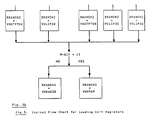
- the first step is to pre-load the branch addresses used in the control flow (Fig. 4) into registers. This is done when the attribute register is loaded by the user.
- the logic in the hardware items in #8 in the last section will set up the branching addresses, which - eliminates the decision making process for each vector; and - eliminates the need for 'return' instructions in subroutines.
- order GDLR3 is taken as an example.
- the order GDLR3 is followed by a data list of (x,y,z) coordinates, x'2AA3' (GDLR3) x1 y1 z1 x2 y2 z2 briefly xn yn zn
- the operation for processing a point (x,y,z) following a GDLR3 order consists of the following three steps:
- the memory fetches for the 3 data words were done in step 1, the GDLR3 pre-processing loop.
- the three memory fetches with the TC processing issue a read for the first data word before entering TC; receive the first data word and issue a read for the second data word during the transformation stage; and receive the second data word and issue a read for the third data word during the clipping stage).
- the first and second data words (x and y) are stored in scratch pad ram during the TC process.
- the memory reads are done in the matrix transformation and clipping stages (this is done to ensure that both reads have been issued in the case where mapping is bypassed because a point is rejected).
- the subroutine that does the GDLR3 data preprocessing for subsequent vectors obtains its x and y data from scratch pad ram, and its z data is already in the memory receive register. There is no need to wait for a memory fetch to complete before re-entering the TC process for the next vector.
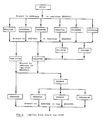
- Fig. 6 The logical flow chart for TC processing of a vector according to a preferred embodiment of the present invention is shown in Fig. 6. and the following is a list of subroutine labels:
- exit registers for the above individual subroutines are:
- the following table shows the different branching addresses loaded into the exit registers when the GLATR order is executed for attribute register.
- exit registers are loaded as follows:
- exit registers For 3D transformed, clipped (non-perspective clipping), and mapped vectors, the exit registers are loaded as follows:
Abstract
Description
- The present invention relates to transforming, clipping and mapping in a graphics display.
- The following are systems representative of the prior art.
- "Fundamentals of Interactive Computer Graphics" by Foley and Van Dam, published by Addison, Wesley Publishing Company, 1982, at
Chapters - However, the text does not teach or suggest the method and apparatus for transformation, clipping and mapping graphics data in accordance with the present invention.
- Bresenham in a article entitled "Algorithm for Computer Control of Digital Plotter", IBM System Journal, Vol. 4
Number 1, 1965, at pages 25-30, describes the basic vector generator which is employed in most graphics display systems. - However, the article does not teach the method for transforming, clipping and mapping graphics data in accordance with the present invention.
- An article entitled "The Design and Implementation of the GINO 3D Graphics Software Package" by P. A. Woodsford, Software Practice and Experience,
Volume 1, pages 335-365, published by John Wiley and Sons, Ltd., 1971, discusses a general purpose graphics software package which provides coordinate transformation and data clipping. - However, the system discussed in the paper does not teach a method for transformation, clipping and mapping of graphics data in accordance with the present invention. An article entitled, "The Adage Graphics Terminal" by Hagan, et. al., published in the Conference Proceedings of the Fall Joint Computer Conference, 1968, describes another prior art design which includes apparatus and method for performing coordinate transformation and image data clipping.
- However, the article does not teach the method for transforming, clipping and mapping graphics data in accordance with the present invention.
- An article entitled "A Clipping Divider" by Sproull and Sutherland, published in the Conference Proceedings, Fall Joint Computer Conference, 1968, at pages 42-52, shows a technique for clipping graphics data against a predetermined clipping window.
- However, the article does not teach the method for transforming, clipping and mapping graphics data in accordance with the present invention.
- According to one aspect of the present invention, there is provided a graphics display system including apparatus for controlling transformation, clipping and mapping therein and comprising means for determining the number of dimensions of a figure to be displayed; means for determining whether a figure is to be transformed and means immediately responsive thereto for transforming the figure; means for determining whether the figure is to be clipped against a predetermined clipping enclosure and means immediately responsive thereto for clipping the figure; and means for drawing the figure as a series of vectors for display on a display device.
- From another aspect of the present invention, there is provided a method for controlling transformation, clipping and mapping in a graphics display system comprising the steps of:
determining the number of dimensions of a figure to be displayed;
determining whether a figure is to be transformed;
if so, transforming the figure;
determining whether the figure is to be clipped against a predetermined clipping enclosure;
if so, clipping the figure; and
drawing the figure as a series of vectors for display on a display device. - In an embodiment of the invention disclosed hereinafter, a graphics display system adapted to control transformation, clipping and mapping therein by a determining the number of dimensions of a figure to be displayed, whether a figure is to be transformed or not, clipped against a predetermined clipping enclosure or not, displayed as a perspective view or not and mapped to a view port or not; and, in response to these determinations to transform, clip, and map as is appropriate prior to drawing the figure as a series of vectors on a display device.
- The display processor in the disclosed raster graphics display system includes means for transformation, clipping and mapping which control the transformation, clipping and mapping of graphics data. A control byte contains 5 bits identified as: M- Window to viewport mapping; P-perspective projection; D-2D/3D mode; T-transformation; and C-clipping. Each bit in the control byte is tested to determine what operations are to be performed on the figure to be drawn. For example, if the D bit is one, indicating a three dimensional figure and the T bit is one, indicating transformation, and the C bit is one, indicating clipping, the P bit determines whether the clipping will be perspective or non-perspective clipping and the M bit determines whether the figure to be drawn is to be mapped to the view port.
- The present invention will be described further by way of example with reference to embodiments of the invention, as illustrated in the accompanying drawing, in which:
- Fig. 1 is a block diagram of the raster graphic display system;
- Fig. 2 is a display processor portion of the system;
- Fig. 3 is a block diagram of logical data flow for the system;
- Fig. 4 is a flow chart showing the transformation, clipping and mapping process performed;
- Fig . 5, in sections 5a and 5b, is a logical flow chart showing loading of exit registers;
- Fig. 6 is a logic flow chart for transformation, clipping and mapping of a vector; and
- Fig. 7 is a flow chart for processing a vector;
- In the drawings, like elements are designated with similar reference numbers, and identical elements in different specific embodiments are designated by identical reference numbers.
- Referring now to Figs. 1 and 2, a Graphics Display Processor which forms part of a Graphics raster Display System will be described.
- Geometric primitives, such as vectors(lines), markers, or polygons(or equivalently, the vertices of polygons); are transformed, clipped and mapped by the method and apparatus according to the present invention.
- The Transformation and Clipping Feature for a Graphics System A Graphics Display Processor for Transformation and Clipping will now be discussed.
- The Graphics Display Processor (see Fig. 2) forms part of a Graphics Raster Display System, see Fig. 1.
- For geometric primitives, such as vectors (lines), markers, or polygons (or equivalently, the vertices of polygons); they go through the transformation-clipping-mapping process.
- Consider the raster graphics system shown in Fig. 1. It consists of the following major components:
- 1. System Control Processor
- 2. Host Communication Interface Processor
- 3. Display Processor
- 4. Hardware Rasteriser - Vector Generator
- 5. Hardware Character Generator
- 6. Video Pixel Memory
- 7. System Memory
- Each of the major components to be described may be implemented by elements of commercially available display systems such as the IBM 5080.
-
- The System Control Processor is a general purpose processor that has master control of the System. The System Control Processor is responsible for servicing all attached Graphics I/O devices
- Coordinating the associated processing with the Display Processor
- the System Control Processor interfaces with the host via the Host Communication Interface Processor
- The Host Communication Interface provides the serial interface of the System to the host. The DP is responsible for
- The Display Processor is responsible for executing graphics orders in the Display Storage Program, residing in the system memory and is concerned mainly with the generation of the image that will appear on the Display Monitor. It has the following functions:
- Decoding graphics orders and executing non-drawing orders; e.g. book keeping and control
- Performing the transformation and clipping function to the geometric primitives: lines, characters, polygons, etc.
- Preparing the following geometric objects for display: lines, characters, markers, filled polygons, by preprocessing and feeding the data to and the Video Pixel Memory. - The Vector Generator is a Hardware Implementation of the Bresenham Line Generating algorithm, which takes the end points of a vector (line) as input, and generates pixels in the Video Pixel Memory as output for display.
- The Vector Pixel Memory consists of 8 1k by 1k bit planes, which supports 256 colours simultaneously via colour look-up tables. The image stored here will be displayed in the Monitor.
- The transformation and clipping method according to the present invention is controlled by the contents of an Attribute Register, which consist of 5 active bits in an 8 bit byte as follows:


- The flow chart for control of the method according to the present invention is shown in Fig. 4. In the following, a vector (line) will be used as an example and the method includes three stages:
- 1. transformation
for the end points of a vector, which is in the 16-bit fixed number format, the matrix multiplication is done in the (-32k,32k-1), 16-bit x,y,and z space. - 2. clipping
using the two end points of a vector (line) and clip to the clipping box specified by the user. The computation is done in 16-bit space - 3. mapping
mapping the contents inside the clipping box (in 3D) or clipping window (in 2D) to a viewport in the screen specified by the user. The screen coordinate is (0,4k-1) by (0,4k-1), which then mapped to the 1k by 1k screen. - For the transformation matrix
m11 m12 m13
m21 m22 m23
m31 m32 m33
m41 m42 m43
the first nine terms are in the 16-bit fraction format; :p.and the last three are in the 16-bit integer format. Furthermore, there is a shift factor ss, where ss runs from 0 to 12 inclusive and is the common exponent for the first 9 terms. - Because the subtraction of two 16-bit numbers may yield a 17-bit number, that is, an overflow, the following number formats are used:
- 1. the input to the matrix multiplication is a 16-bit number
- 2. by shifting to the right, the output from the matrix multiplication (transformation stage), and hence, the input to the clipping stage, is a 15-bit number
- 3. the output from the clipping stage, and input to the mapping stage is a 15-bit number
- 4. the output from the mapping stage, and input to the drawing stage is a 14-bit number (actually between 0 and 1k).
- The Display Processor is a microprogrammed system. It fetches the data from the memory and sends the data out to the raster display via the Vector Generator, which is a rasteriser. It takes the line segment end points coordinates as input, and generates pixels in the video pixel memory.
- The main ingredients of the system are:
- 1. sequencer, e.g. AMD2910A
- 2. 72-bit wide writable control store
- 3. 16-bit ALU, e.g. 4 bit-slice AMD2903
- 4. 16x16 multiplier with 32-bit accumulator, e.g. WTL2010
- 5. 32-bit barrel shifter
- 6. trivial clipper (for checking trivial accept/reject)
- 7. 4k x 16 scratch ram
- 8. logic for microcode next address coming from the content of scratchpad ram registers - indexed addressing.
- The first step is to pre-load the branch addresses used in the control flow (Fig. 4) into registers. This is done when the attribute register is loaded by the user. When a vector is processed, the logic in the hardware items in #8 in the last section will set up the branching addresses, which
- eliminates the decision making process for each vector; and
- eliminates the need for 'return' instructions in subroutines. - When attribute register is loaded, the branch addresses for chaining the transformation subroutines together may be loaded into the exit registers. In our system, three registers (BRANCH1, BRANCH2, and BRANCH3) are used for this purpose, while a fourth register (BRANCH4) is used to return from the vector drawing subroutine to the code that prepares the data for the next vector. A flow chart for loading the exit registers based on the bits in AR is shown in Fig. 5. These registers are described in the section below about Subroutine Exit Registers.
- In this section, the drawing orders are discussed and order GDLR3 is taken as an example. The order GDLR3 is followed by a data list of (x,y,z) coordinates,
x'2AA3' (GDLR3)
x1 y1 z1
x2 y2 z2
................
xn yn zn - The coordinates of each of the n points are of the form
0b0sxxxxxxxxxxxx (X1)
000syyyyyyyyyyyy (Y1)
000szzzzzzzzzzzz (Z1)
where s is the sign bit for the 2's complement number and b is the blanking bit.
- If b = 1, the order is "move" and a move is made to the new current position. i. e., the old current position (X0,Y0,Z0) plus (X1,Y1,Z1), the given relative coordinate
- If b = 0, the order is "draw" and a line is drawn from the old current position (X0,Y0,Z0) to the new one - (X0,Y0,Z0) plus (X1,Y1,Z1), the given relative coordinate.
- As shown in section one, the operation for processing a point (x,y,z) following a GDLR3 order consists of the following three steps:
- 1. GDLR3 preprocessing loop - formatting the coordinate data into 16-bit numbers (bookkeeping)
- 2. TC (transformation and clipping) which consists of the following three stages:
- a transformation (matrix multiplication);
- b clipping;
- c mapping:
- 3. Drawing the transformed-clipped-mapped vector.
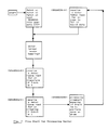
- In the past, the memory fetches for the 3 data words were done in
step 1, the GDLR3 pre-processing loop. To gain performance by overlapping memory fetches with data processing, now interleave the three memory fetches with the TC processing (issue a read for the first data word before entering TC; receive the first data word and issue a read for the second data word during the transformation stage; and receive the second data word and issue a read for the third data word during the clipping stage). - The first and second data words (x and y) are stored in scratch pad ram during the TC process.
- The memory reads are done in the matrix transformation and clipping stages (this is done to ensure that both reads have been issued in the case where mapping is bypassed because a point is rejected).
- If either the matrix transformation or clipping bit is not on, an alternative subroutine is used to fetch the data instead of the transformation or clipping which was bypassed (see descriptions of subroutines VHALF2D, VHALF3D, and VNXTFTCH in the next section).
- For the above reasons, after the first vector is processed by the TC code, the subroutine that does the GDLR3 data preprocessing for subsequent vectors obtains its x and y data from scratch pad ram, and its z data is already in the memory receive register. There is no need to wait for a memory fetch to complete before re-entering the TC process for the next vector.
- See Fig. 7.
- The logical flow chart for TC processing of a vector according to a preferred embodiment of the present invention is shown in Fig. 6. and the following is a list of subroutine labels:
- 1. VCTC - This subroutine is the entry point used whenever any CTC function (transformation, clipping, or mapping) is specified. It records the pre-transformed coordinate values for later use, and remembers the post-transformed coordinate values for the the last point to use CTC
- 2. VX3DCOR - This subroutine performs the 3D matrix transformation in the case where the scale factor is non-zero. In the process of doing this, it converts the x, y, and z coordinates from 16 bit quantities to 15 bit quantities. It also receives the x-coordinate of the next point from memory, and issues a read for the y-coordinate
- 3. VX3DORD - This subroutine performs the 3D matrix transformation in the case where the scale factor is zero. In the process of doing this, it converts the x, y, and z coordinates from 16 bit quantities to 15 bit quantities. It also receives the x-coordinate of the next point from memory, and issues a read for the y-coordinate
- 4. VX2DCOR - This subroutine performs the 2D matrix transformation in the case where the scale factor is non-zero. In the process of doing this, it converts the x and y coordinates from 16 bit quantities to 15 bit quantities. It also receives the x-coordinate of the next point from memory, and issues a read for the y-coordinate
- 5. VX2DORD - This subroutine performs the 2D matrix transformation in the case where the scale factor is zero. In the process of doing this, it converts the x and y coordinates from 16 bit quantities to 15 bit quantities. It also receives the x-coordinate of the next point from memory, and issues a read for the y-coordinate
- 6. VHALF3D - This subroutine is entered in the case where 3D mode was specified and transformation was not specified. It converts the x, y, and z coordinates from 16 bit quantities to 15 bit quantities by dividing them in half. It also receives the x-coordinate of the next point from memory, and issues a read for the y-coordinate
- 7. VHALF2D - This subroutine is entered in the case where 2D mode was specified and transformation was not specified. It converts the x and y coordinates from 16 bit quantities to 15 bit quantities by dividing them in half. It also receives the x-coordinate of the next point from memory, and issues a read for the y-coordinate
- 8. VCLIP3D - This subroutine performs the z-clipping for the 3D non-perspective clipping. When this is completed, it exits to the 2D clipping routine (VCLIP2D) to perform the x and y clipping
- 9. VPERSP - This subroutine performs the z-clipping for the 3D perspective clipping. When this is completed, it exits to the 2D clipping routine (VCLIP2D) to perform the x and y clipping
- 10. VCLIP2D - This subroutine performs the 2D clipping. It also receives the y-coordinate of the next point from memory, and issues a read for the next piece of data (in the case of GDLR3, the z-coordinate)
- 11. VNXTFTCH - This subroutine is entered in the case where no clipping was specified. It receives the y-coordinate of the next proint from memory, and issues a read for the next piece of data (in the case of GDLR3, the z-coordinate)
- 12. VWVMAP - This subroutine performs the window-to-viewport mapping function. If the previous point was clipped, it maps both end points of the current vector; it the previous point was not clipped, only the latest point of the current vector is mapped
- 13. VDRAW3D - This subroutine handles moves and draws in the case when no mapping was specified. It either causes a move or a "move-then-draw" to be done, based on whether blanking was specified or not
- 14. VMOVE3D - This subroutine performs the move needed in the case when mapping is in effect and blanking was specified
- 15. VDRW3D - This subroutine draws the vectors in the case when mapping is in effect, blanking was not specified, and the previous point was not clipped. In this case, there is no need to do a move before drawing (the current draw position of the vector generator is the desired starting position for the vector), so this routine only does a draw
- 16. VMVDRW3D - This subroutine handles drawing in the case when mapping is in effect, blanking was not specified, and the previous point was clipped. In this case, it is necessary to do a move before drawing (the current draw position of the vector generator is not the desired starting point for the vector), so this routine only does a "move-then-draw" operation.
- (Each individual subroutine exits to the address contained in a register which is preloaded during the loading of attribute register.)
- The exit registers for the above individual subroutines are:
- 1. VCTC - BRANCH1
- 2. VX3DCOR - BRANCH2
- 3. VX2DCOR - BRANCH2
- 4. VHALF3D - BRANCH2
- 5. VHALF2D - BRANCH2
- 6. VCLIP3D - exits to entry point in VCLIP2D
- 7. VPERSP - exits to entry point in VCLIP2D
- 8. VCLIP2D - BRANCH3
- 9. VNXTFTCH - BRANCH3
- 10. VWVMAP - exits to one of three "drawing" routines (VMOVE3D, VDRW3D, or VMVDRW3D)
- 11. VDRAW3D - BRANCH4 (return to vector processing code)
- 12 VMOVE3D - BRANCH4 (return to vector processing code)
- 13. VDRW3D - BRANCH4 (return to vector processing code)
- 14. VMVDRW3D - BRANCH4 (return to vector processing code)
- The following table shows the different branching addresses loaded into the exit registers when the GLATR order is executed for attribute register.
- IF D = 0:

- IF D = 1:

- If only 2D transformation with non-zero scale factor is required, the exit registers are loaded as follows:
- 1. address of VX2DCOR in BRANCH1;
- 2. address of VNXTFTCH in BRANCH2;
- 3. address of VDRAW3D in BRANCH3;
- 4. BRANCH4 is loaded with the address of the loop for processing vectors whose coordinate data have been pre-fetched by the previous use of the CTC code.
- For 3D transformed, clipped (non-perspective clipping), and mapped vectors, the exit registers are loaded as follows:
- 1. address of VX3DCOR in BRANCH1
- 2. address of VCLIP3D in BRANCH2
- 3. address of VWVMAP in BRANCH3
- 4. BRANCH4 is loaded with the address of the loop for processing vectors whose coordinate data have been pre-fetched.
- While the present invention has been described with reference to an embodiment thereof, modifications and extensions of application to other picture elements can be incorporated without departing from the scope of the appended claims.
Claims (6)
determining the number of dimensions of a figure to be displayed;
determining whether a figure is to be transformed;
if so, transforming the figure;
determining whether the figure is to be clipped against a predetermined clipping enclosure;
if so, clipping the figure; and
drawing the figure as a series of vectors for display on a display device.
determining whether the figure is to be displayed as a perspective view.
determining whether the figure is to be mapped to a view port; and
if so, mapping the figure to the view port.
Applications Claiming Priority (2)
| Application Number | Priority Date | Filing Date | Title |
|---|---|---|---|
| US821363 | 1986-01-21 | ||
| US06/821,363 US4821209A (en) | 1986-01-21 | 1986-01-21 | Data transformation and clipping in a graphics display system |
Publications (2)
| Publication Number | Publication Date |
|---|---|
| EP0232004A2 true EP0232004A2 (en) | 1987-08-12 |
| EP0232004A3 EP0232004A3 (en) | 1989-04-12 |
Family
ID=25233182
Family Applications (1)
| Application Number | Title | Priority Date | Filing Date |
|---|---|---|---|
| EP87300115A Withdrawn EP0232004A3 (en) | 1986-01-21 | 1987-01-08 | Transforming, clipping and mapping in a graphics display system |
Country Status (4)
| Country | Link |
|---|---|
| US (1) | US4821209A (en) |
| EP (1) | EP0232004A3 (en) |
| JP (1) | JPS62264388A (en) |
| CA (1) | CA1264879C (en) |
Cited By (2)
| Publication number | Priority date | Publication date | Assignee | Title |
|---|---|---|---|---|
| EP0633533A2 (en) * | 1993-07-02 | 1995-01-11 | Sony Corporation | Producing image data representing a picture |
| CN110990106A (en) * | 2019-12-13 | 2020-04-10 | 腾讯云计算(北京)有限责任公司 | Data display method and device, computer equipment and storage medium |
Families Citing this family (31)
| Publication number | Priority date | Publication date | Assignee | Title |
|---|---|---|---|---|
| US5231696A (en) * | 1987-05-14 | 1993-07-27 | France Telecom | Process and circuitry for implementing plotting of overextending curves inside a display window |
| US5003497A (en) * | 1988-12-15 | 1991-03-26 | Sun Micosystems Inc | Method for three-dimensional clip checking for computer graphics |
| US5079545A (en) * | 1989-01-13 | 1992-01-07 | Sun Microsystems, Inc. | Apparatus and method for processing graphical information to minimize page crossings and eliminate processing of information outside a predetermined clip window |
| US4982345A (en) * | 1989-01-23 | 1991-01-01 | International Business Machines Corporation | Interactive computer graphics display system processing method for identifying an operator selected displayed object |
| US4970636A (en) * | 1989-01-23 | 1990-11-13 | Honeywell Inc. | Memory interface controller |
| US5051737A (en) * | 1989-02-23 | 1991-09-24 | Silicon Graphics, Inc. | Efficient graphics process for clipping polygons |
| EP0569758A3 (en) * | 1992-05-15 | 1995-03-15 | Eastman Kodak Co | Method and apparatus for creating and storing three-dimensional font characters and performing three-dimensional typesetting. |
| US5684937A (en) * | 1992-12-14 | 1997-11-04 | Oxaal; Ford | Method and apparatus for performing perspective transformation on visible stimuli |
| US6307559B1 (en) | 1995-07-13 | 2001-10-23 | International Business Machines Corporation | Method and apparatus for color space conversion, clipping, and scaling of an image during blitting |
| US7542035B2 (en) * | 1995-11-15 | 2009-06-02 | Ford Oxaal | Method for interactively viewing full-surround image data and apparatus therefor |
| US6137497A (en) * | 1997-05-30 | 2000-10-24 | Hewlett-Packard Company | Post transformation clipping in a geometry accelerator |
| US5877773A (en) * | 1997-05-30 | 1999-03-02 | Hewlett-Packard Company | Multi-pass clipping in a geometry accelerator |
| US7450165B2 (en) * | 2003-05-02 | 2008-11-11 | Grandeye, Ltd. | Multiple-view processing in wide-angle video camera |
| US20050007453A1 (en) * | 2003-05-02 | 2005-01-13 | Yavuz Ahiska | Method and system of simultaneously displaying multiple views for video surveillance |
| US7528881B2 (en) * | 2003-05-02 | 2009-05-05 | Grandeye, Ltd. | Multiple object processing in wide-angle video camera |
| US7529424B2 (en) * | 2003-05-02 | 2009-05-05 | Grandeye, Ltd. | Correction of optical distortion by image processing |
| US20100002070A1 (en) | 2004-04-30 | 2010-01-07 | Grandeye Ltd. | Method and System of Simultaneously Displaying Multiple Views for Video Surveillance |
| US20050028215A1 (en) * | 2003-06-03 | 2005-02-03 | Yavuz Ahiska | Network camera supporting multiple IP addresses |
| US7119808B2 (en) * | 2003-07-15 | 2006-10-10 | Alienware Labs Corp. | Multiple parallel processor computer graphics system |
| US20080211816A1 (en) * | 2003-07-15 | 2008-09-04 | Alienware Labs. Corp. | Multiple parallel processor computer graphics system |
| US7893985B1 (en) | 2004-03-15 | 2011-02-22 | Grandeye Ltd. | Wide angle electronic camera with improved peripheral vision |
| US8427538B2 (en) * | 2004-04-30 | 2013-04-23 | Oncam Grandeye | Multiple view and multiple object processing in wide-angle video camera |
| US7366359B1 (en) | 2004-07-08 | 2008-04-29 | Grandeye, Ltd. | Image processing of regions in a wide angle video camera |
| US7990422B2 (en) * | 2004-07-19 | 2011-08-02 | Grandeye, Ltd. | Automatically expanding the zoom capability of a wide-angle video camera |
| US20060062478A1 (en) * | 2004-08-16 | 2006-03-23 | Grandeye, Ltd., | Region-sensitive compression of digital video |
| US8860780B1 (en) | 2004-09-27 | 2014-10-14 | Grandeye, Ltd. | Automatic pivoting in a wide-angle video camera |
| US9141615B1 (en) | 2004-11-12 | 2015-09-22 | Grandeye, Ltd. | Interactive media server |
| US7894531B1 (en) | 2005-02-15 | 2011-02-22 | Grandeye Ltd. | Method of compression for wide angle digital video |
| US8723951B2 (en) * | 2005-11-23 | 2014-05-13 | Grandeye, Ltd. | Interactive wide-angle video server |
| US7991225B2 (en) * | 2006-03-03 | 2011-08-02 | University Of Alaska | Methods and systems for dynamic color equalization |
| US8767009B1 (en) * | 2012-06-26 | 2014-07-01 | Google Inc. | Method and system for record-time clipping optimization in display list structure |
Citations (2)
| Publication number | Priority date | Publication date | Assignee | Title |
|---|---|---|---|---|
| US3816726A (en) * | 1972-10-16 | 1974-06-11 | Evans & Sutherland Computer Co | Computer graphics clipping system for polygons |
| EP0112942A1 (en) * | 1982-12-30 | 1984-07-11 | International Business Machines Corporation | Graphics display system and method |
Family Cites Families (12)
| Publication number | Priority date | Publication date | Assignee | Title |
|---|---|---|---|---|
| JPS5533286A (en) * | 1978-08-31 | 1980-03-08 | Fujitsu Ltd | Data processor |
| US4449201A (en) * | 1981-04-30 | 1984-05-15 | The Board Of Trustees Of The Leland Stanford Junior University | Geometric processing system utilizing multiple identical processors |
| NL8300872A (en) * | 1983-03-10 | 1984-10-01 | Philips Nv | MULTIPROCESSOR CALCULATOR SYSTEM FOR PROCESSING A COLORED IMAGE OF OBJECT ELEMENTS DEFINED IN A HIERARCHICAL DATA STRUCTURE. |
| US4645459A (en) * | 1982-07-30 | 1987-02-24 | Honeywell Inc. | Computer generated synthesized imagery |
| US4667190A (en) * | 1982-07-30 | 1987-05-19 | Honeywell Inc. | Two axis fast access memory |
| DE3381300D1 (en) * | 1983-03-31 | 1990-04-12 | Ibm | IMAGE ROOM MANAGEMENT AND PLAYBACK IN A PART OF THE SCREEN OF A VIRTUAL MULTIFUNCTIONAL TERMINAL. |
| US4679038A (en) * | 1983-07-18 | 1987-07-07 | International Business Machines Corporation | Band buffer display system |
| US4646075A (en) * | 1983-11-03 | 1987-02-24 | Robert Bosch Corporation | System and method for a data processing pipeline |
| JPS60181977A (en) * | 1984-02-29 | 1985-09-17 | Usac Electronics Ind Co Ltd | Line drawing processing system |
| JPS60241175A (en) * | 1984-05-16 | 1985-11-30 | Mitsubishi Electric Corp | Graphic processor |
| US4625289A (en) * | 1985-01-09 | 1986-11-25 | Evans & Sutherland Computer Corp. | Computer graphics system of general surface rendering by exhaustive sampling |
| US4651278A (en) * | 1985-02-11 | 1987-03-17 | International Business Machines Corporation | Interface process for an all points addressable printer |
-
1986
- 1986-01-21 US US06/821,363 patent/US4821209A/en not_active Expired - Fee Related
- 1986-11-25 CA CA523775A patent/CA1264879C/en not_active Expired
- 1986-11-28 JP JP61282230A patent/JPS62264388A/en active Granted
-
1987
- 1987-01-08 EP EP87300115A patent/EP0232004A3/en not_active Withdrawn
Patent Citations (2)
| Publication number | Priority date | Publication date | Assignee | Title |
|---|---|---|---|---|
| US3816726A (en) * | 1972-10-16 | 1974-06-11 | Evans & Sutherland Computer Co | Computer graphics clipping system for polygons |
| EP0112942A1 (en) * | 1982-12-30 | 1984-07-11 | International Business Machines Corporation | Graphics display system and method |
Non-Patent Citations (2)
| Title |
|---|
| COMPUTER, vol. 13, no. 7, July 1980, pages 59-68, Long Beach, US; J. CLARK: "A VLSI geometry processor for graphics" * |
| IBM TECHNICAL DISCLOSURE BULLETIN, vol. 20, no. 10, March 1978, pages 4137-4143, New York, US; M.A. McMORRAN et al.: "Graphic display system" * |
Cited By (5)
| Publication number | Priority date | Publication date | Assignee | Title |
|---|---|---|---|---|
| EP0633533A2 (en) * | 1993-07-02 | 1995-01-11 | Sony Corporation | Producing image data representing a picture |
| EP0633533A3 (en) * | 1993-07-02 | 1995-05-10 | Sony Corp | Producing image data representing a picture. |
| US5805135A (en) * | 1993-07-02 | 1998-09-08 | Sony Corporation | Apparatus and method for producing picture data based on two-dimensional and three dimensional picture data producing instructions |
| CN110990106A (en) * | 2019-12-13 | 2020-04-10 | 腾讯云计算(北京)有限责任公司 | Data display method and device, computer equipment and storage medium |
| CN110990106B (en) * | 2019-12-13 | 2023-03-31 | 腾讯云计算(北京)有限责任公司 | Data display method and device, computer equipment and storage medium |
Also Published As
| Publication number | Publication date |
|---|---|
| CA1264879A (en) | 1990-01-23 |
| EP0232004A3 (en) | 1989-04-12 |
| CA1264879C (en) | 1990-01-23 |
| JPH0572627B2 (en) | 1993-10-12 |
| US4821209A (en) | 1989-04-11 |
| JPS62264388A (en) | 1987-11-17 |
Similar Documents
| Publication | Publication Date | Title |
|---|---|---|
| US4821209A (en) | Data transformation and clipping in a graphics display system | |
| US6417858B1 (en) | Processor for geometry transformations and lighting calculations | |
| US6005580A (en) | Method and apparatus for performing post-process antialiasing of polygon edges | |
| US4679041A (en) | High speed Z-buffer with dynamic random access memory | |
| US6650327B1 (en) | Display system having floating point rasterization and floating point framebuffering | |
| WO2000019377B1 (en) | Graphics processor with deferred shading | |
| KR19990072375A (en) | Rapid computation of local eye vectors in a fixed point lighting unit | |
| US5003497A (en) | Method for three-dimensional clip checking for computer graphics | |
| US4811241A (en) | Clipping of fixed character strings in a graphics system | |
| GB2226479A (en) | Method and apparatus for fractional double buffering | |
| US5303321A (en) | Integrated hardware generator for area fill, conics and vectors in a graphics rendering processor | |
| EP0261390B1 (en) | Matrix concatenation in a graphics display system | |
| US5912830A (en) | System and method for conditionally calculating exponential values in a geometry accelerator | |
| US5295234A (en) | Apparatus for displaying a three dimensional object which appears substantially the same in different display directions by modifying stored image data by a scale factor | |
| KR19980702733A (en) | 3D graphic display | |
| US4870599A (en) | Traversal method for a graphics display system | |
| US5265210A (en) | Method and apparatus for plotting pixels to approximate a straight line on a computer display device without substantial irregularities | |
| US6681237B1 (en) | Exponentiation circuit for graphics adapter | |
| US5710879A (en) | Method and apparatus for fast quadrilateral generation in a computer graphics system | |
| US5297244A (en) | Method and system for double error antialiasing in a computer display system | |
| CA1264878A (en) | Circle/ellipse generation in a graphics system | |
| US5375196A (en) | Rapid line drawing in computer graphics employing floating-point arithmetic | |
| KR100260040B1 (en) | Method and apparatus for determining texture coordinates in computer graphics | |
| EP0389890A2 (en) | Method and apparatus for generating figures with three degrees of freedom | |
| JPH0696231A (en) | Method and device for graphic display |
Legal Events
| Date | Code | Title | Description |
|---|---|---|---|
| PUAI | Public reference made under article 153(3) epc to a published international application that has entered the european phase |
Free format text: ORIGINAL CODE: 0009012 |
|
| AK | Designated contracting states |
Kind code of ref document: A2 Designated state(s): DE FR GB IT |
|
| 17P | Request for examination filed |
Effective date: 19871202 |
|
| PUAL | Search report despatched |
Free format text: ORIGINAL CODE: 0009013 |
|
| AK | Designated contracting states |
Kind code of ref document: A3 Designated state(s): DE FR GB IT |
|
| 17Q | First examination report despatched |
Effective date: 19910208 |
|
| STAA | Information on the status of an ep patent application or granted ep patent |
Free format text: STATUS: THE APPLICATION HAS BEEN WITHDRAWN |
|
| 18W | Application withdrawn |
Withdrawal date: 19940408 |
|
| APAF | Appeal reference modified |
Free format text: ORIGINAL CODE: EPIDOSCREFNE |
|
| RIN1 | Information on inventor provided before grant (corrected) |
Inventor name: HEMPEL, BRUCE CARLTON Inventor name: LIANG; BOB CHAO-CHU |