EP0233449B1 - Apparatus and method for controlling ignition timing for internal combustion engine - Google Patents
Apparatus and method for controlling ignition timing for internal combustion engine Download PDFInfo
- Publication number
- EP0233449B1 EP0233449B1 EP87100095A EP87100095A EP0233449B1 EP 0233449 B1 EP0233449 B1 EP 0233449B1 EP 87100095 A EP87100095 A EP 87100095A EP 87100095 A EP87100095 A EP 87100095A EP 0233449 B1 EP0233449 B1 EP 0233449B1
- Authority
- EP
- European Patent Office
- Prior art keywords
- ignition timing
- engine speed
- adv
- correction amount
- timing correction
- Prior art date
- Legal status (The legal status is an assumption and is not a legal conclusion. Google has not performed a legal analysis and makes no representation as to the accuracy of the status listed.)
- Expired - Lifetime
Links
Images


Classifications
-
- B—PERFORMING OPERATIONS; TRANSPORTING
- B65—CONVEYING; PACKING; STORING; HANDLING THIN OR FILAMENTARY MATERIAL
- B65D—CONTAINERS FOR STORAGE OR TRANSPORT OF ARTICLES OR MATERIALS, e.g. BAGS, BARRELS, BOTTLES, BOXES, CANS, CARTONS, CRATES, DRUMS, JARS, TANKS, HOPPERS, FORWARDING CONTAINERS; ACCESSORIES, CLOSURES, OR FITTINGS THEREFOR; PACKAGING ELEMENTS; PACKAGES
- B65D63/00—Flexible elongated elements, e.g. straps, for bundling or supporting articles
- B65D63/10—Non-metallic straps, tapes, or bands; Filamentary elements, e.g. strings, threads or wires; Joints between ends thereof
-
- F—MECHANICAL ENGINEERING; LIGHTING; HEATING; WEAPONS; BLASTING
- F02—COMBUSTION ENGINES; HOT-GAS OR COMBUSTION-PRODUCT ENGINE PLANTS
- F02P—IGNITION, OTHER THAN COMPRESSION IGNITION, FOR INTERNAL-COMBUSTION ENGINES; TESTING OF IGNITION TIMING IN COMPRESSION-IGNITION ENGINES
- F02P5/00—Advancing or retarding ignition; Control therefor
- F02P5/04—Advancing or retarding ignition; Control therefor automatically, as a function of the working conditions of the engine or vehicle or of the atmospheric conditions
- F02P5/145—Advancing or retarding ignition; Control therefor automatically, as a function of the working conditions of the engine or vehicle or of the atmospheric conditions using electrical means
- F02P5/15—Digital data processing
- F02P5/1502—Digital data processing using one central computing unit
- F02P5/1504—Digital data processing using one central computing unit with particular means during a transient phase, e.g. acceleration, deceleration, gear change
-
- F—MECHANICAL ENGINEERING; LIGHTING; HEATING; WEAPONS; BLASTING
- F02—COMBUSTION ENGINES; HOT-GAS OR COMBUSTION-PRODUCT ENGINE PLANTS
- F02P—IGNITION, OTHER THAN COMPRESSION IGNITION, FOR INTERNAL-COMBUSTION ENGINES; TESTING OF IGNITION TIMING IN COMPRESSION-IGNITION ENGINES
- F02P5/00—Advancing or retarding ignition; Control therefor
- F02P5/04—Advancing or retarding ignition; Control therefor automatically, as a function of the working conditions of the engine or vehicle or of the atmospheric conditions
- F02P5/045—Advancing or retarding ignition; Control therefor automatically, as a function of the working conditions of the engine or vehicle or of the atmospheric conditions combined with electronic control of other engine functions, e.g. fuel injection
-
- F—MECHANICAL ENGINEERING; LIGHTING; HEATING; WEAPONS; BLASTING
- F02—COMBUSTION ENGINES; HOT-GAS OR COMBUSTION-PRODUCT ENGINE PLANTS
- F02P—IGNITION, OTHER THAN COMPRESSION IGNITION, FOR INTERNAL-COMBUSTION ENGINES; TESTING OF IGNITION TIMING IN COMPRESSION-IGNITION ENGINES
- F02P5/00—Advancing or retarding ignition; Control therefor
- F02P5/04—Advancing or retarding ignition; Control therefor automatically, as a function of the working conditions of the engine or vehicle or of the atmospheric conditions
- F02P5/145—Advancing or retarding ignition; Control therefor automatically, as a function of the working conditions of the engine or vehicle or of the atmospheric conditions using electrical means
- F02P5/15—Digital data processing
- F02P5/1502—Digital data processing using one central computing unit
- F02P5/151—Digital data processing using one central computing unit with means for compensating the variation of the characteristics of the engine or of a sensor, e.g. by ageing
-
- F—MECHANICAL ENGINEERING; LIGHTING; HEATING; WEAPONS; BLASTING
- F02—COMBUSTION ENGINES; HOT-GAS OR COMBUSTION-PRODUCT ENGINE PLANTS
- F02P—IGNITION, OTHER THAN COMPRESSION IGNITION, FOR INTERNAL-COMBUSTION ENGINES; TESTING OF IGNITION TIMING IN COMPRESSION-IGNITION ENGINES
- F02P5/00—Advancing or retarding ignition; Control therefor
- F02P5/04—Advancing or retarding ignition; Control therefor automatically, as a function of the working conditions of the engine or vehicle or of the atmospheric conditions
- F02P5/145—Advancing or retarding ignition; Control therefor automatically, as a function of the working conditions of the engine or vehicle or of the atmospheric conditions using electrical means
- F02P5/15—Digital data processing
- F02P5/1502—Digital data processing using one central computing unit
- F02P5/1514—Digital data processing using one central computing unit with means for optimising the use of registers or of memories, e.g. interpolation
-
- Y—GENERAL TAGGING OF NEW TECHNOLOGICAL DEVELOPMENTS; GENERAL TAGGING OF CROSS-SECTIONAL TECHNOLOGIES SPANNING OVER SEVERAL SECTIONS OF THE IPC; TECHNICAL SUBJECTS COVERED BY FORMER USPC CROSS-REFERENCE ART COLLECTIONS [XRACs] AND DIGESTS
- Y02—TECHNOLOGIES OR APPLICATIONS FOR MITIGATION OR ADAPTATION AGAINST CLIMATE CHANGE
- Y02T—CLIMATE CHANGE MITIGATION TECHNOLOGIES RELATED TO TRANSPORTATION
- Y02T10/00—Road transport of goods or passengers
- Y02T10/10—Internal combustion engine [ICE] based vehicles
- Y02T10/40—Engine management systems
Landscapes
- Engineering & Computer Science (AREA)
- Mechanical Engineering (AREA)
- Chemical & Material Sciences (AREA)
- Combustion & Propulsion (AREA)
- General Engineering & Computer Science (AREA)
- Theoretical Computer Science (AREA)
- Signal Processing (AREA)
- Electrical Control Of Ignition Timing (AREA)
- Package Frames And Binding Bands (AREA)
- Table Devices Or Equipment (AREA)
- Gloves (AREA)
Description
- The present invention relates to an apparatus and method for controlling ignition timing for an internal combustion engine, and in particular, to such apparatus and method capable of suppressing variations in revolution of the internal combustion engine.
- Recently, a phenomenon of irregular vibrations has been noticed as a problem in which in an automobile having an internal combustion engine mounted thereon, the irregular vibrations (so-called surging) are caused in the automobile when a resonance frequency determined by the internal combustion engine and the car body matches with the engine rotational speed (rpm) of the internal combustion engine.
- In order to eliminate this phenomenon, for example, as disclosed in U.S. Patent No. 4,527,523, it has been proposed to control the ignition timing.
- However, in the case of this U.S. Patent, since it is arranged to detect an actual engine speed (rpm) through a filter, and to compare the actual engine speed with an engine speed processed through the filter thereby to provide discrimination, it is impossible to detect a variation in the revolution at an early time. And furthermore, since a time point at which the ignition timing is corrected and the amount of correction are not optimum, the effect of suppressing the vibrations has not been so satisfactory as expected.
- It is an object of the present invention to provide an apparatus and method for controlling ignition timing of an internal combustion engine capable of obtaining a satisfactory suppressing effect of vibrations.
- The above object is achieved according to the claims, the dependent claims relating to preferred embodiments.
- The method of the present invention for controlling the ignition timing of internal combustion engines comprises the steps of
- (a) Detecting the engine speed;
- (b) determining the engine speed change rate;
- (c) discriminating whether the engine speed change rate is higher than a predetermined value;
- (d) discriminating the direction of change of the engine speed by determining the sign of the change rate;
- (e) determining a fundamental ignition timing amount on the basis of operational conditions of the engine;
- (f) determining an ignition timing correction amount, and
- (g) determining a final ignition timing amount by additively correcting the fundamental ignition timing amount by means of the ignition timing correction amount, when the engine speed change rate is larger than the predetermined value, it is characterized in that the ignition timing correction amount is determined on the basis of the result of the discrimination steps c and d in such a manner that no ignition timing correction amount is applied for a predetermined number of ignitions following inversion of the sign of the change rate signal, and an ignition timing correction amount depending on the number of ignitions following the sign inversion is applied for a predetermined number of ignitions following the number of non-corrected ignitions.
- In accordance with another embodiment, the method of the present invention as defined above is characterized in that it is discriminated whether the engine is in a specific operational condition or not, and the ignition timing correction amounts are made different depending on whether the engine is in a specific operational condition or not.
- The ignition timing control apparatus for internal combustion engines according to the present invention comprises:
- (A) Engine speed detecting means for detecting the engine speed represented by an engine speed signal;
- (B) differentiation means for differentiating the engine speed signal and generating a corresponding engine speed change rate signal;
- (C) change rate discriminating means for discriminating whether the engine speed change rate signal is larger than a predetermined value;
- (D) change direction discriminating means for discriminating the direction of change of the engine speed signal, by determining the sign of the change rate signal;
- (E) basic ignition timing amount determining means for determining a fundamental ignition timing amount on the basis of operating conditions of the engine;
- (F) ignition timing correcting means for determining an ignition timing correction amount,
and - (G) final ignition timing amount determining means for determining a final ignition timing amount by additively correcting the fundamental ignition timing amount by means of the ignition timing correction amount when the engine speed change rate signal is larger than the predetermined value, as determined by the change rate discriminating means; it is characterized in that the ignition timing correcting means are designed such as to determine the ignition timing correction amount on the basis of the results determined by the change rate discriminating means and the change direction discriminating means in such a manner that no ignition timing correction amount is applied for a predetermined number of ignitions following inversion of the sign of the change rate signal, and an ignition timing correction amount depending on the number of ignitions following the sign inversion is applied for a predetermined number of ignitions following the number of non-corrected ignitions.
- In accordance with another embodiment, the ignition timing control apparatus as defined above is characterized in that condition discriminating means are provided for discriminating whether the engine is in a specific operational condition or not, and the ignition timing correcting means are designed such as to determine ignition timing correction amounts which are different depending on whether the engine is in a specific operational condition or not.
- A method of controlling the ignition timing of internal combustion engines comprising the above-defined features a to g and an apparatus comprising the features A to G as defined above is known from FR-A-2 531 145. In this prior art, no speed change rate dependent signal is used for determining the fundamental ignition timing amount.
- US-A-4 498 438 describes a similar ignition timing control system where a speed change is determined by determining the difference between the actual engine speed value and an averaged value obtained from previously detected speed values, and the basic ignition timing value is corrected in accordance with this difference.
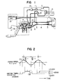
- Fig. 1 is a system diagram of the present invention;
Fig 2 is a characteristic diagram of engine speed (rpm) and ignition timing;
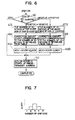
Fig. 3 is a block diagram illustrating an embodiment of the present invention;
Fig. 4 is a block diagram of an arrangement of a control unit;
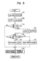
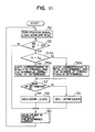
Figs. 5 and 6 are respectively flowcharts of an embodiment of the present invention;
Fig. 7 is a graph of a relationship between the number of ignitions and the amount of correction;
Figs. 8, 9A and 9B are characteristic diagrams showing relationships between the engine speed and the ignition timing;
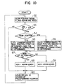
Figs. 10, 11, 12, 15 and 16 are flowcharts of other embodiments of the present invention;
Fig. 13 is a characteristic diagram of an amount of correction with respect to a variation in revolution; and
Fig. 14 is a graph for determining a correction area based on the engine speed and load. - Hereinafter, embodiments of the present invention will be described. Firstly, an overall system of a fuel injection apparatus implementing the present invention will be described with reference to Figs. 1 to 4. In Fig. 1, air is introduced from an
inlet portion 2 of an air cleaner 1, and passes through a hot wire typeair flow meter 3 detecting sucked air volume, aduct 4, and athrottle body 5 having a throttle valve for controlling air flow, and enters into a collector 6. Here, the air is distributed to eachintake manifold 8 communicating directly with an internal combustion engine 7, and is sucked into a cylinder. On the other hand, fuel is sucked and pressured by afuel pump 10 from a fuel tank 9, and is supplied to a fuel system including a fuel damper 11, afuel filter 12, aninjection valve 13 and afuel regulator 14. The fuel is adjusted to a constant pressure by thefuel regulator 14, and is injected into theintake manifold 8 from theinjection valve 13. Further, a signal indicative of a detected amount of air sucked therein is outputted from theair flow meter 3, and this output signal is inputted to acontrol unit 15. A crank angle sensor 16a is built in adistributor 16, and outputs reference signals for fuel injection timing and ignition timing as well as a signal representing a detected engine speed, and these signals are supplied to thecontrol unit 15. - Next, the control of the ignition timing in accordance with the present invention will be described in detail with reference to Figs. 2 and 3. In Fig. 2, the engine speed (rpm) is shown in the upper portion of the figure, and the behavior of the ignition timing is shown in the lower portion. In Fig. 2, the ignition timing is obtained by differentiating an amount of change in the engine speed (dN/dt) and by considering the sign of the dN/dt which indicates that when the engine speed is decreasing, the sign is negative and when it is increasing, the sign is positive. Thus, the stair-shaped curve representing the ignition timing shows that the ignition timing is retarded when the rate of change is larger than a predetermined value and the sign is positive, and the ignition timing is advanced when the sign is negative.
- The control mentioned above is achieved by a basic arrangement as described below.
- In Fig. 3, an engine speed signal N detected by the
crank angle sensor 16 is converted to a differentiated signal Ṅ in a differentiated value generating means 17. The differentiated signal Ṅ is supplied to a change rate discriminating means 18 for discriminating whether or not a change rate of the engine speed larger than a predetermined value Ṅpre is caused or not, and is further supplied to a signdiscriminating means 19 for discriminating a direction of change in the engine speed. And based on the results of both thediscriminating means - On the other hand, a fundamental ignition amount ADVM is obtained in a fundamental ignition timing amount determining means 21 based on the engine speed signal N and an air volume signal Qa, correction ignition timing amount ΔADV from the correction ignition timing amount determining means 20 and the fundamental ignition timing amount ADVM from the fundamental ignition amount determining means 21 are summed in a final ignition timing amount determining means 22 to produce a final ignition timing amount ADV.
- The manner of control described above is a basic principle of the instant embodiment, and it can be performed also by using a computer.
- The
control unit 15 is, as shown in Fig. 4, composed of an MPU, a RAM, a ROM, and an I/O device including an A/D converter and an input/output circuit. Thecontrol unit 15 performs predetermined computation and processing based on the output signal from theair flow meter 3 and the output signals from thecrank angle sensor 16, etc., and an output signal of thecontrol unit 15, representing the results of the computation is supplied to thefuel injection valve 13 to actuate so that a required amount of fuel is injected into eachintake manifold 8. Further, it is designed to control the ignition timing by supplying a signal from thecontrol unit 15 to a power transistor which controls a primary current of an ignition coil. - With reference to a flowchart of Fig. 5, the control performed in the case using such a control unit will be described.
- An engine speed N, and an air volume Qa are detected.
- A fundamental ignition timing amount ADVM determined by N and Qa is obtained.
- This fundamental ignition timing amount ADVM has been stored in the ROM as a map.
- A differentiated value Ṅ (= dN/dt) of the engine speed N is obtained, and it is discriminated whether this differentiated value Ṅ is larger than a predetermined value Ṅpre (= ΔN) or not.
- When the differentiated value Ṅ is larger than Ṅpre as discriminated in
step 34, a correction ignition timing amount ΔADV is retrieved from the ROM in this step. - By discriminating the sign of the differentiated value Ṅ, it is discriminated whether the engine speed N is increasing or decreasing.
- The correction ignition timing amount ΔADV is added to or subtracted from the fundamental ignition timing amount ADVM, and a final ignition timing amount ADV is obtained.
- The ignition timing amount ADVM or ADV determined in the
steps - As described above, in this embodiment, as shown in Fig. 2, in the vicinity of inflexion points CU and CB, since dN/dt is smaller than the predetermined value, the correction of the ignition timing is not carried out, and a retrieved value from the ROM is outputted as it is. When the engine speed N is decreasing and dN/dt is larger than the predetermined value, since the sign is negative, a predetermined amount is added to the retrieved value from the ROM, and the ignition timing is advanced. Further, when the engine speed is increasing and dN/dt is larger than the predetermined value, since the sign is positive, a predetermined amount is subtracted from the map-retrieved value, and the ignition timing is retarded.
- Accordingly, in the vicinity of the inflexion points (Fig. 2) at which the rate of change in the engine speed is small, the correction of the ignition timing is not carried out, and instead, at a portion at which the rate of change in the engine speed is large, the ignition timing is advanced if the engine speed is decreasing thereby to increase a torque, and the ignition timing is retarded when the engine speed is increasing thereby to decrease the torque. As a result, a satisfactory effect of suppressing the vibrations can be attained.
- Next, a second embodiment will be described with reference to Figs. 6 to 8.
- Through
step 34, it is discriminated by a differentiated value Ṅ (= dN/dt) whether the engine speed N has been changed from an increasing trend to a decreasing trend. - The number of ignitions is counted from a time at which the differentiated value Ṅ is changed from a positive sign to a negative sign, or from the negative sign to the positive sign.
- In correspondence to the number of ignitions determined in
steps - In this table, as shown in Fig. 7, at the time of a first ignition, no correction is carried out (a retrieved value ADVM from the ROM is outputted), and the amount of correction is increased at a second ignition and is further increased at a third ignition. At a fourth ignition, the amount of correction is decreased to become equal to that at the second ignition, and no correction is effected at a fifth ignition.
In this manner, the correction is carried out successively as shown in Fig. 8. - The correction ignition timing amount ΔADV obtained in
step - The fundamental ignition timing amount ADVM obtained in
Step 32 and the final ignition timing amount ADV obtained inStep 49A or 49B are stored at predetermined addresses of the RAM. - By processing as described in the foregoing, the characteristics of the engine speed and the ignition timing as shown in Fig. 8 can be obtained.
- Also in this embodiment, in the vicinity of the inflexion points at which a rate of change in the engine speed is small, no correction of the ignition timing is carried out, and at portions with a large rate of change in the engine speed, the ignition timing is advanced if the engine speed is decreasing thereby to increase the torque, and the ignition timing is retarded if the engine speed is increasing thereby to enable to decrease the torque. In particular, in this embodiment, as shown in Fig. 8, a maximum correction is applied at points CM at which the differentiated value is maximum.
- Next, a third embodiment will be described.
- In the embodiments described in the foregoings, the ignition timing is corrected by using the correction amount and the number of corrections which are predetermined based on limited factors, even when the revolution period is changed. In contrast, the vibration suppressing effect is further improved in another embodiment which will be explained hereinafter.
- The characteristic feature of this embodiment resides in that the number of corrections and the correction amount are changed in correspondence to a change in period of the revolution variation.
- Fig. 9A shows a change in the engine speed and ignition timing when a transmission is shifted to a first gear position, and Fig. 9B shows a change in the engine speed and ignition timing when the transmission is shifted to a second gear position.
- As will be seen from the figure, the period and amplitude of revolution variation differ between the first gear position and the second gear position, and there is a problem in that when the number of corrections and the amount of correction are determined uniformly, the surging is promoted, and irregular vibrations occur due to excessively large torque.
- For this reason, in this embodiment of the present invention, as shown in Fig. 10, it is designed to change the correction amount and the number of corrections such as shown in Figs. 9A and 9B as examples, depending on a gear position.
- With reference to Fig. 10, the operation will be described.
- In this step, a gear position signal and an actual engine speed N are read, and a fundamental ignition timing amount ADVM is read from a memory map.
- In this step, it is decided whether a change in the engine speed per a predetermined time dN/dt is larger than a predetermined engine speed change ΔN or not.
- When the engine speed change dN/dt has been decided as being larger in
step 53, in this step, a gear position is decided as to whether it is in a first position or in a second position. - After the gear position has been decided in
step 54, based on this decision, a correction ignition timing amount ΔADV and a number of corrections are decided in correspondence with the gear position. -
- In this step, it is decided whether a change in the engine speed is positive or negative. That is, a direction of change in the engine speed is decided.
- In these steps, the correction amount ΔADV obtained in
steps 54 to 57 is added to or subtracted from the fundamental ignition timing amount ADVM. - In this step, the final ignition timing amount ADV obtained in
steps - And, in the control of the ignition timing, as shown in Figs. 9A and 9B, the correction amount and the number of corrections are changed depending on the gear position whether it is in the first or second position.
- Further, in this respect, the correction amount and the number of corrections may be changed, as shown in Fig. 11, using a predetermined changeover engine speed as a boundary. Such a control will be described with reference to Fig. 11, and the explanation of identifical steps to that in Fig. 10 is omitted.
- In this step, it is decided whether the engine speed N is larger than a changeover engine speed Nn or not.
- In these steps, a correction amount △ADV and the number of corrections are determined in a similar manner as in the embodiment of Fig. 10.
- In this embodiment, since the correction ignition timing amount and the number of corrections are changed depending on the gear position and the engine speed, the fine and precise control of the ignition timing is made possible, and the vibration suppressing effect can be improved.
- Next, a fourth embodiment of the present invention will be described.
- In the third embodiment, the correction ignition timing amount is changed from one value to the other in a manner as in switching operation depending on the gear position and the engine speed. In contrast, in the fourth embodiment, it is characterized in that the correction ignition timing amount is changed gradually.
- This embodiment will be described with reference to Fig. 12.
- In this step, based on outputs from the crank angle sensor and the air flow meter, an engine speed N at the present time is obtained and further, a fundamental ignition timing amount ADVM is obtained from a memory map.
- The engine speed N obtained in
step 61 is differentiated, and it is decided whether a differentiated value dN/dt is larger than a predetermined value ΔN or not. - When it is decided in
step 62 that the engine speed is changing, the changing rate dN/dt is decided as to its magnitude, and a correction amount ΔADV corresponding to the value is obtained from a memory map having a characteristic as shown in Fig. 13. - It is decided whether the differentiated value dN/dt of the engine speed obtained in
step 61 is positive or negative thereby to determine whether the engine speed is in an increasing direction or in a decreasing direction. - When it is decided that the engine speed is in the increasing direction in
step 64, the correction amount ΔADV obtained instep 63 is subtracted from the fundamental ignition timing amount ADVM to obtain a final ignition timing amount ADV. - When it is decided that the engine speed is in the decreasing direction, the correction amount ΔADV obtained in
step 63 is added to the fundamental ignition timing amount ADVM to obtain a final ignition timing amount ADV. - In this step, the fundamental ignition timing amount ADVM obtained in
step 61, and the correction amount obtained instep - Next, a fifth embodiment will be described in which the fifth embodiment is a modification of the fourth embodiment.
- There is a problem in that when the control of the fourth embodiment is carried out in an operating area of the engine in which the ignition timing control is not necessary because of a relationship between the engine speed and the surging, the engine performance is degraded conversely, and the utilization efficiency of the microcomputer is lowered.
- Accordingly, in the modified embodiment, it is designed to perform the aforementioned fundamental control only in a predetermined range of the engine speed.
- In Fig. 14, the ignition timing control is carried out in a range of the engine speed, that is above N₁ and below N₂. N₁ corresponds to about 600 rpm and N₂ corresponds to 1200 rpm, and a further condition is that a clutch is meeting.
- The reason for selecting N₁ as 600 rpm is based on the findings in which at the time when the clutch meets, the engine speed decreases, and thus when the aforementioned fundamental control is carried out, it results in the control for advancing the ignition timing, and the output of the engine to cope with the load is decreased. On the other hand, the reason for selecting N₂ as 1200 rpm is that the surging is essentially difficult to occur at the engine speed above 1200 rpm, and when the execution of the fundamental control is continued even at the engine speed above 1200 rpm a control time is needed for the microcomputer superfluously and the utilization efficiency is lowered.
- Further, the correction area can be defined also by load. The load is obtained from a pulse width Tp applied to the injection valve, and it is possible to determine that the control is carried out in a range wherein the load is smaller than a predetermined value TPl.
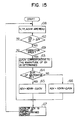
- The control mentioned above will be described in detail with reference to a flowchart in Fig. 15 wherein steps bearing identical numerals to that in Fig. 12 indicate identical processings.
- In this step, the engine speed N, load Tp and fundamental ignition timing amount ADVM are read.
- The same processing is carried out as in the step in Fig. 12.
- When it is decided that a variation in the engine speed is equal to or larger than a predetermined value in
step 62, it is decided in this step as to whether a correction of the ignition timing is really necessary or not. - The conditions for this decision are shown in Fig. 14 in that the ignition timing is corrected when the clutch is meeting and the engine speed N is in the range of N₁ ≦ N ≦ N₂, or further, the ignition timing is corrected when the load TP is smaller than the predetermined value TPl.
- When it is decided that the operating parameters are in the correction area in step 69, the same processing as in
step 63 in Fig. 12 is performed. - The same processing is performed as in Fig. 12.
- The same processing is performed as in Fig. 12.
- The same processing is performed as in Fig. 12.
- The same processing is performed as in Fig. 12.
- In this manner, by setting the correction area, the correction of the ignition timing is carried out only for the really required operating area, and thus the problems of degradation of the engine performance and decrease of the utilization of the microcomputer can be obviated.
- The degree of suppression of vibrations due to surging in the engine differs depending on the load on the engine. In other words, even when the change in the engine speed is the same, and hence even when the same correction of the ignition timing is applied, the vibration suppressing effect differs depending on whether the transmission is at a neutral position or at any of the other positions. Thus, when the correction appropriate in the case of the neutral gear position is applied in other cases, the vibration suppressing effect is reduced.
- For this reason, by changing the correction amount depending on the gear positions, an optimum vibration suppressing effect can be obtained at the neutral position as well as at the other gear positions.
- Hereinafter, the operation will be described with reference to a flowchart in Fig. 16.
- In this step, the gear position is read from a neutral switch, and further, an engine speed N at the present time and a fundamental ignition timing ADVM are read.
- The same processing is carried out as in Fig. 12.
- In this step, it is decided whether the neutral switch is at an ON position, that is, a neutral position, or at any of the other gear positions.
- When it is decided that the neutral switch is at the ON position in step 71, a correction amount ΔADV corresponding to a change in the engine speed dN is obtained from a characteristic curve GON of the memory map in Fig. 13.
- When it is decided that the neutral switch is at an OFF position in step 71, a correction amount ΔADV corresponding to the change in the engine speed dN is obtained from a characteristic curve GOFF in the memory map in Fig. 13.
- The same processing is carried out as in Fig. 12.
- The same processing is carried out as in Fig. 12.
- The same processing is carried out as in Fig. 12.
- The same processing is carried out as in Fig. 12.
- As described in the foregoing, the gear position is decided whether it is at the neutral position or at any of the other positions, and depending on this decision, the correction amount is changed even when the change in the engine speed is the same. As a result, an optimum vibration suppressing effect can be obtained.
Claims (17)
- A method for controlling the ignition timing of internal combustion engines, comprising the steps of:(a) Detecting the engine speed (N);(b) determining the engine speed change rate (dN/dt);(c) discriminating whether the engine speed change rate (dN/dt) is higher than a predetermined value;(d) discriminating the direction of change of the engine speed (N) by determining the sign of the change rate (dN/dt);(e) determining a fundamental ignition timing amount (ADVM) on the basis of operational conditions (N, Qa) of the engine;(f) determining an ignition timing correction amount (△ ADV),
and(g) determining a final ignition timing amount (ADV) by additively correcting the fundamental ignition timing amount (ADVM) by means of the ignition timing correction amount (△ ADV), when the engine speed change rate (dN/dt) is larger than the predetermined value,characterized in that
the ignition timing correction amount (△ ADV) is determined on the basis of the result of the discrimination steps c and d in such a manner that no ignition timing correction amount (△ ADV) is applied for a predetermined number of ignitions following inversion of the sign of the change rate signal (dN/dt), and an ignition timing correction amount (△ ADV) depending on the number of ignitions following the sign inversion is applied for a predetermined number of ignitions following the number of non-corrected ignitions. - The method according to claim 1, characterized in that it is discriminated whether the engine is in a specific operational condition (N, gear position) or not, and the ignition timing correction amounts (△ ADV) are made different depending on whether the engine is in a specific operational condition or not.
- The method according to claims 1 and 2, characterized in that the gear position is discriminated, and the ignition timing correction amount (△ ADV) is determined such that the lower the gear position the larger the ignition timing correction amount (△ ADV).
- The method according to claims 1 to 3, characterized in that it is discriminated whether or not the engine speed (N) is equal to or larger than a predetermined value (Nn), and the ignition timing correction amount (△ ADV) is determined such that the higher the engine speed (N) the larger the ignition timing correction amount (△ ADV).
- The method according to claims 1 to 4, characterized in that the ignition timing correction amount (△ ADV) is determined in proportionality to the engine speed change rate (dN/dt).
- The method according to claims 1 to 5, characterized in that it is detected whether the engine speed (N) is within a predetermined range, and determination of the ignition timing correction amount (△ ADV) is carried out only when the engine speed (N) is within the predetermined speed range.
- The method according to claim 6, characterized in that it is detected whether the engine load is equal to or smaller than a predetermined value, and the ignition timing correction amount (△ ADV) is determined only when the load is equal to or smaller than the predetermined value, and when the engine speed (N) is within the predetermined speed range.
- The method according to claims 1 to 7, characterized in that it is detected whether the gear position is neutral or not, and the ignition timing correction amount (△ ADV) is determined such as to be smaller for neutral gear position than for other gear positions.
- The method according to claims 1 to 8, characterized in that the ignition timing correction amount (△ ADV) is determined such as to have a maximum value at the time point at which the engine speed change rate (dN/dt) is maximum.
- An ignition timing control apparatus for internal combustion engines, particularly for carrying out the method according to claims 1 to 9,
comprising:(A) Engine speed detecting means (16; 30; 52; 61; 68; 70) for detecting the engine speed represented by an engine speed signal (N);(B) differentiation means (17) for differentiating the engine speed signal (N) and generating a corresponding engine speed change rate signal (dN/dt);(C) change rate discriminating means (18; 34; 53; 62) for discriminating whether the engine speed change rate signal (dN/dt) is larger than a predetermined value;(D) change direction discriminating means (19; 38; 57; 64) for discriminating the direction of change of the engine speed signal (N) by determining the sign of the change rate signal (dN/dt);(E) basic ignition timing amount determining means (21; 32) for determining a fundamental ignition timing amount (ADVM) on the basis of operating conditions (N, Qa) of the engine;(F) ignition timing correcting means (20) for determining an ignition timing correction amount (△ ADV),
and(G) final ignition timing amount determining means (22; 40, 42; 49A; 49B; 58, 59; 65, 66) for determining a final ignition timing amount (ADV) by additively correcting the fundamental ignition timing amount (ADVM) by means of the ignition timing correction amount (△ ADV) when the engine speed change rate signal (dN/dt) is larger than the predetermined value, as determined by the change rate discriminating means (18; 34; 53; 62),characterized in that the ignition timing correcting means (20; 36; 48A, 48B) are designed such as to determine the ignition timing correction amount (△ ADV) on the basis of the results determined by the change rate discriminating means (18; 34; 53; 62) and the change direction discriminating means (19; 38; 57; 64) in such a manner that no ignition timing correction amount (△ ADV) is applied for a predetermined number of ignitions following inversion of the sign of the change rate signal (dN/dt), and an ignition timing correction amount (△ ADV) depending on the number of ignitions following the sign inversion is applied for a predetermined number of ignitions following the number of non-corrected ignitions. - The apparatus according to claim 10, characterized in that condition discriminating means (54; 54A) are provided for discriminating whether the engine is in a specific operational condition (N, gear position) or not, and the ignition timing correcting means (20) are designed such as to determine ignition timing correction amounts (△ ADV) which are different depending on whether the engine is in a specific operational condition or not.
- The apparatus according to claim 11, characterized in that the condition discriminating means (54) discriminate the gear position, and the ignition timing correcting means (20) determine the ignition timing correction amount (△ ADV) such that the lower the gear position the larger the ignition timing correction amount (△ ADV).
- The apparatus according to claim 11, characterized in that the condition discriminating means (54A) discriminate whether or not the engine speed (N) is equal to or larger than a predetermined value (Nn), and the ignition timing correcting means (20) determine the ignition timing correction amount (△ ADV) such that the higher the engine speed (N) the larger the ignition timing correction amount (△ ADV).
- The apparatus according to claims 10 to 13, characterized in that the ignition timing correcting means (20) are designed such as to determine the ignition timing correction amount (△ ADV) in proportionality to the engine speed change rate (dN/dt).
- The apparatus according to claims 10 to 14, characterized in that it comprises speed range detecting means (69) for detecting that the engine speed (N) is within a predetermined range, and the ignition timing correcting means (20) are designed such as to determine an ignition timing correction amount (△ ADV) only when the engine speed (N) is within the predetermined speed range.
- The apparatus according to claim 15, characterized in, that it comprises load detecting means (Fig. 14) for detecting that the engine load is equal to or smaller than a predetermined value, and the ignition timing correcting means (20) are designed such as to determine an ignition correction amount (△ ADV) only when the load is equal to or smaller than the predetermined value and when the engine speed (N) is within the predetermined speed range.
- The apparatus according to claims 10 to 16, characterized in that it comprises neutral detecting means (71) for detecting whether the gear position is neutral or not, and the ignition timing correcting means (20) are designed such as to determine the ignition timing correction amount (△ ADV) to be smaller for neutral gear position than for other gear positions.
Applications Claiming Priority (2)
| Application Number | Priority Date | Filing Date | Title |
|---|---|---|---|
| JP61000614A JP2511862B2 (en) | 1986-01-08 | 1986-01-08 | Ignition timing control method for internal combustion engine |
| JP614/86 | 1986-01-08 |
Publications (2)
| Publication Number | Publication Date |
|---|---|
| EP0233449A1 EP0233449A1 (en) | 1987-08-26 |
| EP0233449B1 true EP0233449B1 (en) | 1991-06-12 |
Family
ID=11478610
Family Applications (1)
| Application Number | Title | Priority Date | Filing Date |
|---|---|---|---|
| EP87100095A Expired - Lifetime EP0233449B1 (en) | 1986-01-08 | 1987-01-07 | Apparatus and method for controlling ignition timing for internal combustion engine |
Country Status (5)
| Country | Link |
|---|---|
| US (1) | US4799469A (en) |
| EP (1) | EP0233449B1 (en) |
| JP (1) | JP2511862B2 (en) |
| KR (2) | KR870007358A (en) |
| DE (1) | DE3770652D1 (en) |
Families Citing this family (35)
| Publication number | Priority date | Publication date | Assignee | Title |
|---|---|---|---|---|
| US4843556A (en) * | 1985-07-23 | 1989-06-27 | Lucas Industries Public Limited Company | Method and apparatus for controlling an internal combustion engine |
| GB8700759D0 (en) * | 1987-01-14 | 1987-02-18 | Lucas Ind Plc | Adaptive control system |
| DE3871832T2 (en) * | 1987-03-25 | 1993-01-14 | Japan Electronic Control Syst | DEVICE FOR IGNITION CONTROL AND FOR SUPPRESSING INTERFERENCE VIBRATIONS DURING THE ACCELERATION OF AN INTERNAL COMBUSTION ENGINE. |
| GB8715130D0 (en) * | 1987-06-27 | 1987-08-05 | Lucas Ind Plc | Adaptive control system for i c engine |
| GB8721688D0 (en) * | 1987-09-15 | 1987-10-21 | Lucas Ind Plc | Adaptive control system |
| JPH01100379A (en) * | 1987-10-09 | 1989-04-18 | Daihatsu Motor Co Ltd | Surging preventive method for engine |
| JP2646216B2 (en) * | 1987-10-29 | 1997-08-27 | 三信工業株式会社 | Ignition timing control device for two-stroke internal combustion engine |
| JP2701270B2 (en) * | 1987-11-05 | 1998-01-21 | 株式会社日立製作所 | Ignition advance control device |
| JP2585312B2 (en) * | 1987-11-09 | 1997-02-26 | 日産自動車株式会社 | Ignition timing control device for internal combustion engine |
| US4945875A (en) * | 1988-03-07 | 1990-08-07 | Mitsubishi Denki Kabushiki Kaisha | Electronic ignition timing control device |
| WO1989009332A1 (en) * | 1988-03-25 | 1989-10-05 | Robert Bosch Gmbh | An electronic control device for modulating fuel quantities in an internal combustion engine |
| JPH086667B2 (en) * | 1988-04-15 | 1996-01-29 | 株式会社日立製作所 | Ignition timing control device for internal combustion engine |
| US5021956A (en) * | 1988-04-25 | 1991-06-04 | Mazda Motor Corporation | Control systems for vehicle engines coupled with automatic transmissions |
| GB8810878D0 (en) * | 1988-05-07 | 1988-06-08 | Lucas Ind Plc | Adaptive control system for i c engine |
| JPH0223268A (en) * | 1988-07-13 | 1990-01-25 | Toyota Motor Corp | Ignition timing control device for internal combustion engine |
| JPH0814271B2 (en) * | 1988-09-12 | 1996-02-14 | 日産自動車株式会社 | Ignition timing control device for internal combustion engine |
| DE3884206D1 (en) * | 1988-12-02 | 1993-10-21 | Siemens Ag | Method for controlling the ignition angle of an internal combustion engine. |
| JP2544472B2 (en) * | 1989-03-01 | 1996-10-16 | 株式会社日立製作所 | Combustion control device for multi-cylinder engine |
| JP3085382B2 (en) * | 1989-08-25 | 2000-09-04 | 株式会社日立製作所 | Method for controlling combustion state of internal combustion engine |
| DE4011386A1 (en) * | 1990-04-07 | 1991-10-10 | Bosch Gmbh Robert | METHOD FOR ADJUSTING ANGLE IN LOAD CHANGES |
| US5452698A (en) * | 1990-05-07 | 1995-09-26 | Robert Bosch Gmbh | Device for suppressing discontinuous motion of a moving motor vehicle |
| FR2678986A1 (en) * | 1991-07-09 | 1993-01-15 | Siemens Automotive Sa | PROCESS FOR CORRECTING THE TRANSITIONAL ADVANCE ON IGNITION OF AN INTERNAL COMBUSTION ENGINE AND ITS APPLICATION TO SMOOTHING THE IMPROVEMENTS OF THE ENGINE RPM. |
| FR2680203B1 (en) * | 1991-08-06 | 1993-11-05 | Siemens Automotive Sa | METHOD FOR SMOOTHING A-ACCELERATION SPEEDS OF A VEHICLE POWERED BY AN INTERNAL COMBUSTION ENGINE. |
| JP2833935B2 (en) * | 1992-07-10 | 1998-12-09 | 三菱電機株式会社 | Internal combustion engine control device |
| DE4232204C2 (en) * | 1992-09-25 | 1995-11-02 | Siemens Ag | Method for suppressing vibrations in the drive train of a motor vehicle |
| FR2713286B1 (en) * | 1993-11-30 | 1996-01-05 | Renault | Method for correcting the torque surges of an internal combustion engine. |
| US5701865A (en) * | 1996-04-26 | 1997-12-30 | Chrysler Corporation | Method of adjusting idle spark for an individual cylinder of an internal combustion engine |
| US6892702B2 (en) * | 2000-10-12 | 2005-05-17 | Kabushiki Kaisha Moric | Ignition controller |
| JP2002202038A (en) * | 2001-01-09 | 2002-07-19 | Honda Motor Co Ltd | Ignition timing control device of engine |
| US20030015175A1 (en) * | 2001-07-18 | 2003-01-23 | Andersson Martin N. | Ignition timing control system for light duty combustion engines |
| US7198028B2 (en) * | 2001-07-18 | 2007-04-03 | Walbro Engine Management, L.L.C. | Ignition timing control system for light duty combustion engines |
| US6814053B2 (en) * | 2002-11-06 | 2004-11-09 | Detroit Diesel Corporation | Method and apparatus for limiting engine operation in a programmable range |
| WO2007032020A2 (en) * | 2005-07-01 | 2007-03-22 | Bajaj Auto Limited | Method and system for controlling engine noise |
| GB0705024D0 (en) * | 2007-03-15 | 2007-04-25 | Delphi Tech Inc | Vehicle diagnosis device and method |
| JP6621787B2 (en) * | 2017-10-19 | 2019-12-18 | 本田技研工業株式会社 | Ignition timing control device for internal combustion engine |
Family Cites Families (14)
| Publication number | Priority date | Publication date | Assignee | Title |
|---|---|---|---|---|
| FR1377282A (en) * | 1963-03-07 | 1964-11-06 | Renault | Method and device for obtaining by varying the advance the deceleration of the engine of a motor vehicle provided with an automatic gearbox |
| DE2961307D1 (en) * | 1978-08-09 | 1982-01-14 | Bosch Gmbh Robert | Ignition and fuel injection control system for internal combustion engines |
| US4276860A (en) * | 1979-11-01 | 1981-07-07 | Motorola, Inc. | Apparatus for the generation of monostable pulses having predetermined durations independent of input signal period |
| JPS56113049A (en) * | 1980-02-12 | 1981-09-05 | Nissan Motor Co Ltd | Ignition timing control method |
| FR2477236B1 (en) * | 1980-03-03 | 1987-04-17 | Mitsubishi Electric Corp | IGNITION POINT CONTROL SYSTEM FOR AN INTERNAL COMBUSTION ENGINE |
| JPS5738642A (en) * | 1980-08-19 | 1982-03-03 | Nippon Denso Co Ltd | Method of internal-combustion engine control |
| JPS57143161A (en) * | 1981-03-02 | 1982-09-04 | Nippon Denso Co Ltd | Ignition time controlling method for internal combustion engine |
| JPS5848738A (en) * | 1981-09-16 | 1983-03-22 | Toyota Motor Corp | Apparatus for suppressing and controlling vibration of vehicle |
| US4424783A (en) * | 1981-11-11 | 1984-01-10 | General Motors Corporation | Combustion chamber inlet temperature corrected combustion initiation timing |
| FR2531145B1 (en) * | 1982-07-27 | 1987-04-30 | Marchal Equip Auto | METHOD OF SELF-ADAPTIVE REGULATION OF THE ANGLE OF ADVANCE ON IGNITION OF A CONTROLLED IGNITION HEAT ENGINE |
| DE3242483A1 (en) * | 1982-11-18 | 1984-05-24 | Vdo Adolf Schindling Ag, 6000 Frankfurt | ELECTRICAL DEVICE FOR ELIMINATING VEHICLE JUMPING |
| DE3243235A1 (en) * | 1982-11-23 | 1984-05-24 | Robert Bosch Gmbh, 7000 Stuttgart | DEVICE FOR DAMPING VIBRATION VIBRATIONS IN AN INTERNAL COMBUSTION ENGINE IN A MOTOR VEHICLE |
| JPS606071A (en) * | 1983-06-24 | 1985-01-12 | Toyota Motor Corp | Control method for knocking in internal-combustion engine |
| JPS6259741U (en) * | 1985-10-03 | 1987-04-14 |
-
1986
- 1986-01-08 JP JP61000614A patent/JP2511862B2/en not_active Expired - Lifetime
-
1987
- 1987-01-05 US US07/000,446 patent/US4799469A/en not_active Expired - Lifetime
- 1987-01-06 KR KR870000027A patent/KR870007358A/en not_active IP Right Cessation
- 1987-01-07 EP EP87100095A patent/EP0233449B1/en not_active Expired - Lifetime
- 1987-01-07 DE DE8787100095T patent/DE3770652D1/en not_active Expired - Lifetime
-
1988
- 1988-01-06 KR KR1019870000027A patent/KR930009908B1/en not_active Application Discontinuation
Also Published As
| Publication number | Publication date |
|---|---|
| JP2511862B2 (en) | 1996-07-03 |
| KR870007358A (en) | 1987-08-18 |
| DE3770652D1 (en) | 1991-07-18 |
| KR890011761A (en) | 1989-08-22 |
| KR930009908B1 (en) | 1993-10-13 |
| JPS62159771A (en) | 1987-07-15 |
| EP0233449A1 (en) | 1987-08-26 |
| US4799469A (en) | 1989-01-24 |
Similar Documents
| Publication | Publication Date | Title |
|---|---|---|
| EP0233449B1 (en) | Apparatus and method for controlling ignition timing for internal combustion engine | |
| US4852537A (en) | Ignition timing control apparatus for internal combustion engine | |
| US4596217A (en) | Method and system to prevent knocking operation of an internal combustion engine | |
| US4582032A (en) | Ignition timing control system for internal combustion engine | |
| US4509331A (en) | Knock-free engine control system for turbocharged automotive engine | |
| KR100679475B1 (en) | Method for suppressing engine knocking in an internal combustion engine | |
| US4425890A (en) | Spark timing control apparatus for use with a internal combustion engine | |
| US4636957A (en) | Method for controlling operating state of an internal combustion engine with an overshoot preventing function | |
| US4508079A (en) | Knocking control system for internal combustion engine | |
| EP0921296B1 (en) | A fuel injection control device for an internal combustion engine | |
| EP0345814B1 (en) | Electric control apparatus for automobile and method of compensating for time delay of measured data | |
| JPH07208309A (en) | Method and equipment for controlling internal combustion engine | |
| US5174259A (en) | Fuel injection control system for turbocharged diesel engine | |
| US5058550A (en) | Method for determining the control values of a multicylinder internal combustion engine and apparatus therefor | |
| EP0337491B1 (en) | Apparatus and method for controlling ignition timing of internal combustion engines | |
| US4367711A (en) | Method and apparatus for ignition system spark timing control within warm-up period of the engine | |
| KR100317158B1 (en) | Idling speed control system of internal combustion engine | |
| US4370968A (en) | Electronically controlled, fuel injection method | |
| EP0347756A2 (en) | Control system for boost pressure in internal combustion engine with turbocharger | |
| EP0216291B2 (en) | A process for controlling an internal combustion engine | |
| EP0098584B2 (en) | An ignition timing control method for internal combustion engines | |
| EP0980972B1 (en) | Apparatus and method for controlling fuel injection in internal combustion engine | |
| US4909217A (en) | Electronic-type engine control method | |
| EP0196657B1 (en) | Electronic fuel injection method and apparatus for internal combustion engine | |
| US4785779A (en) | Internal combustion engine control apparatus |
Legal Events
| Date | Code | Title | Description |
|---|---|---|---|
| PUAI | Public reference made under article 153(3) epc to a published international application that has entered the european phase |
Free format text: ORIGINAL CODE: 0009012 |
|
| AK | Designated contracting states |
Kind code of ref document: A1 Designated state(s): DE GB |
|
| 17P | Request for examination filed |
Effective date: 19870828 |
|
| 17Q | First examination report despatched |
Effective date: 19890602 |
|
| GRAA | (expected) grant |
Free format text: ORIGINAL CODE: 0009210 |
|
| AK | Designated contracting states |
Kind code of ref document: B1 Designated state(s): DE GB |
|
| REF | Corresponds to: |
Ref document number: 3770652 Country of ref document: DE Date of ref document: 19910718 |
|
| PLBE | No opposition filed within time limit |
Free format text: ORIGINAL CODE: 0009261 |
|
| STAA | Information on the status of an ep patent application or granted ep patent |
Free format text: STATUS: NO OPPOSITION FILED WITHIN TIME LIMIT |
|
| 26N | No opposition filed | ||
| REG | Reference to a national code |
Ref country code: GB Ref legal event code: IF02 |
|
| PGFP | Annual fee paid to national office [announced via postgrant information from national office to epo] |
Ref country code: GB Payment date: 20020107 Year of fee payment: 16 |
|
| PGFP | Annual fee paid to national office [announced via postgrant information from national office to epo] |
Ref country code: DE Payment date: 20020328 Year of fee payment: 16 |
|
| PG25 | Lapsed in a contracting state [announced via postgrant information from national office to epo] |
Ref country code: GB Free format text: LAPSE BECAUSE OF NON-PAYMENT OF DUE FEES Effective date: 20030107 |
|
| PG25 | Lapsed in a contracting state [announced via postgrant information from national office to epo] |
Ref country code: DE Free format text: LAPSE BECAUSE OF NON-PAYMENT OF DUE FEES Effective date: 20030801 |
|
| GBPC | Gb: european patent ceased through non-payment of renewal fee |
Effective date: 20030107 |