EP0240838A2 - Apparatus for molding thermoplastic pipes - Google Patents
Apparatus for molding thermoplastic pipes Download PDFInfo
- Publication number
- EP0240838A2 EP0240838A2 EP87104375A EP87104375A EP0240838A2 EP 0240838 A2 EP0240838 A2 EP 0240838A2 EP 87104375 A EP87104375 A EP 87104375A EP 87104375 A EP87104375 A EP 87104375A EP 0240838 A2 EP0240838 A2 EP 0240838A2
- Authority
- EP
- European Patent Office
- Prior art keywords
- halves
- molding
- circulating
- shanks
- run
- Prior art date
- Legal status (The legal status is an assumption and is not a legal conclusion. Google has not performed a legal analysis and makes no representation as to the accuracy of the status listed.)
- Withdrawn
Links
Images


Classifications
-
- B—PERFORMING OPERATIONS; TRANSPORTING
- B29—WORKING OF PLASTICS; WORKING OF SUBSTANCES IN A PLASTIC STATE IN GENERAL
- B29D—PRODUCING PARTICULAR ARTICLES FROM PLASTICS OR FROM SUBSTANCES IN A PLASTIC STATE
- B29D23/00—Producing tubular articles
- B29D23/24—Endless tubes, e.g. inner tubes for pneumatic tyres
-
- B—PERFORMING OPERATIONS; TRANSPORTING
- B29—WORKING OF PLASTICS; WORKING OF SUBSTANCES IN A PLASTIC STATE IN GENERAL
- B29C—SHAPING OR JOINING OF PLASTICS; SHAPING OF MATERIAL IN A PLASTIC STATE, NOT OTHERWISE PROVIDED FOR; AFTER-TREATMENT OF THE SHAPED PRODUCTS, e.g. REPAIRING
- B29C49/00—Blow-moulding, i.e. blowing a preform or parison to a desired shape within a mould; Apparatus therefor
- B29C49/0015—Making articles of indefinite length, e.g. corrugated tubes
- B29C49/0021—Making articles of indefinite length, e.g. corrugated tubes using moulds or mould parts movable in a closed path, e.g. mounted on movable endless supports
-
- B—PERFORMING OPERATIONS; TRANSPORTING
- B29—WORKING OF PLASTICS; WORKING OF SUBSTANCES IN A PLASTIC STATE IN GENERAL
- B29C—SHAPING OR JOINING OF PLASTICS; SHAPING OF MATERIAL IN A PLASTIC STATE, NOT OTHERWISE PROVIDED FOR; AFTER-TREATMENT OF THE SHAPED PRODUCTS, e.g. REPAIRING
- B29C49/00—Blow-moulding, i.e. blowing a preform or parison to a desired shape within a mould; Apparatus therefor
- B29C49/42—Component parts, details or accessories; Auxiliary operations
- B29C49/56—Opening, closing or clamping means
-
- B—PERFORMING OPERATIONS; TRANSPORTING
- B29—WORKING OF PLASTICS; WORKING OF SUBSTANCES IN A PLASTIC STATE IN GENERAL
- B29C—SHAPING OR JOINING OF PLASTICS; SHAPING OF MATERIAL IN A PLASTIC STATE, NOT OTHERWISE PROVIDED FOR; AFTER-TREATMENT OF THE SHAPED PRODUCTS, e.g. REPAIRING
- B29C55/00—Shaping by stretching, e.g. drawing through a die; Apparatus therefor
- B29C55/22—Shaping by stretching, e.g. drawing through a die; Apparatus therefor of tubes
- B29C55/24—Shaping by stretching, e.g. drawing through a die; Apparatus therefor of tubes radial
-
- B—PERFORMING OPERATIONS; TRANSPORTING
- B29—WORKING OF PLASTICS; WORKING OF SUBSTANCES IN A PLASTIC STATE IN GENERAL
- B29C—SHAPING OR JOINING OF PLASTICS; SHAPING OF MATERIAL IN A PLASTIC STATE, NOT OTHERWISE PROVIDED FOR; AFTER-TREATMENT OF THE SHAPED PRODUCTS, e.g. REPAIRING
- B29C49/00—Blow-moulding, i.e. blowing a preform or parison to a desired shape within a mould; Apparatus therefor
- B29C49/42—Component parts, details or accessories; Auxiliary operations
- B29C49/56—Opening, closing or clamping means
- B29C2049/566—Locking means
- B29C2049/5661—Mechanical
Definitions
- This invention relates to apparatus for molding thermoplastic pipes, externally ribbed or corrugated.
- the apparatus of the first known patent is particularly adapted to produce externally ribbed pipes. That is why it has a means for withstanding the hydraulic pressure of molding acting to separate the halves in the straight forward run in said perpendicular direction.
- said means constitutes two guiding rails biased toward each other by means of springs.
- the drawback of such a design lies in extremely high loads and wear in the rails since the hydraulic pressure of the injection molding acts in the frame-springs-rail-halves-rail-frame zone.
- the patent does not states whether the halves are independent (chainless) or are parts of chains.
- the chainless apparatus with independent halves are designed for molding of corrugated pipes and do not have said means and, in addition, cannot withstand the hydraulic pressure of molding acting to separate the halves in the direction of their circulation. That is why, such apparatus cannot be used successfully in the molding of externally ribbed pipes.
- the objective of the present invention is to overcome the above drawbacks of the known apparatus.
- the frame and guides are unloaded from the pressure by means of yokes fixing the halves to each other.
- the hydraulic pressure acts only in the halves-yokes-halves zone.
- the means for withstanding the hydraulic pressure is represented by two endless series of circulating yokes having shanks for engagement along said travelling mold with complimentary recesses made in the halves. The yokes withstand the pressure in both said directions.
- the yokes are provided with rollers, said series being supplied with a track having appropriate upstream, downstream, forward and return sections for guiding said rollers in such a manner that in the upstream and downstream sections the shanks are driven toward and away from the recesses in a progressive motion without changing their orientation and without their undercutting, and are engaged with the recesses in the forward section.
- the upstream and downstream sections have separate parallel guiding paths ensuring said progressive motion.
- the apparatus of the present invention includes two trains of moldblock halves 2 driven in an endless paths by means of sprockets 4 engaged with roller pins 5 of the halves 2.
- the paths have straight forward (6) and return (8) runs and semi-circumferential guide tracks 10 and 12 for transferring the halves 2 between the runs 6 and 8.
- the halves 2 are adjacent to each other in the runs 6 and 8 and cooperate with those of the opposite path in the run 6 to form a travelling mold for the produced thermoplastic pipe 14 extruded from a pipe die 16.
- the straight forward runs 6 is provided with an upstreamly located series 18 and 20 of circulating yokes 22 having shanks 24 for engagement along the travelling mold with complimentary recesses 26 made in the halves 2.
- the yokes 22 are provided with rollers 30.
- the series 18 and 20 have upstream (32), downstream (34), forward (36) and return (38) sections, the sections 32 and 34 being provided with separate parallel guiding paths 40 and 42.
- the shanks can be conical or cylindrical, can belong to the halves (in which case the complimentary recesses are made in the yokes), the upstream and/or downstream sections can be provided with a rotary transfer (shown as a sprocket 44 in Fig. 4), the series can be represented by a chain, etc.
- an extrudate of the thermoplastic material flows from the die 16 into the travelling mold.
- the hydraulic pressure of the melt acting to separate the halves 2 in the run 6 is accepted by yokes 22 engaged with the recesses 26 in the forward section 36, no forces being transferred farther the halves.
- the paths 40 and 42 guide the shanks 24 in the upstream and downstream sections 32 and 34 appropriately in such a manner that they are driven toward and away from the recesses 26 in a progressive motion without changing their orientation. This allows to avoid mutual undercutting of the shanks and recesses.
- the present apparatus is directed mostly to externally ribbed pipes production (the process being close to injection molding), in rare cases the apparatus may be applied to withstand the blow pressure in blow molding of extremely large pipes.
Abstract
Description
- This invention relates to apparatus for molding thermoplastic pipes, externally ribbed or corrugated.
- Known such apparatus (U.S. patents Nos. 3,998,579, 4,021,178 and my U.S. patent No. 4,504,206) include a pipe die for extruding a parison of a thermoplastic material, and moldblock halves circulating in an endless path containing a straight forward run wherein the halves cooperate with each other in the directions of their circulation and perpendicularly to the latter, to form a travelling mold for the thermoplastic pipe, a return run and two semi-circumferential guide tracks for transferring the halves between said runs.
- The apparatus of the first known patent is particularly adapted to produce externally ribbed pipes. That is why it has a means for withstanding the hydraulic pressure of molding acting to separate the halves in the straight forward run in said perpendicular direction.
- In that apparatus said means constitutes two guiding rails biased toward each other by means of springs. The drawback of such a design lies in extremely high loads and wear in the rails since the hydraulic pressure of the injection molding acts in the frame-springs-rail-halves-rail-frame zone. Also, the patent does not states whether the halves are independent (chainless) or are parts of chains. The chainless apparatus with independent halves (described in the next two patents) are designed for molding of corrugated pipes and do not have said means and, in addition, cannot withstand the hydraulic pressure of molding acting to separate the halves in the direction of their circulation. That is why, such apparatus cannot be used successfully in the molding of externally ribbed pipes.
- Similar problems can arise in blow molding of extremely large corrugated pipes.
- The objective of the present invention is to overcome the above drawbacks of the known apparatus.
- For this the frame and guides are unloaded from the pressure by means of yokes fixing the halves to each other. Thus, in the present invention the hydraulic pressure acts only in the halves-yokes-halves zone. The means for withstanding the hydraulic pressure is represented by two endless series of circulating yokes having shanks for engagement along said travelling mold with complimentary recesses made in the halves. The yokes withstand the pressure in both said directions.
- The yokes are provided with rollers, said series being supplied with a track having appropriate upstream, downstream, forward and return sections for guiding said rollers in such a manner that in the upstream and downstream sections the shanks are driven toward and away from the recesses in a progressive motion without changing their orientation and without their undercutting, and are engaged with the recesses in the forward section.
- The upstream and downstream sections have separate parallel guiding paths ensuring said progressive motion.
- To render justice, it should be noted that the objective of creating progressive motion is known in the art of corrugators for driving the halves (U.S. patent No. 4,021,178 and my U.S. patent No. 4,504,206).
- A more complete appreciation of the present invention and the distinguishing characteristics, objectives and attendant advantages thereof set out herein are more apparent and obvious to one ordinary skilled in the art from the following detailed description, drawings and appended claims.
-
- Fig. 1 is an apparatus of the present invention, a side view;
- Fig. 2 is the same as above, a plan view elevation of circulating yokes series;
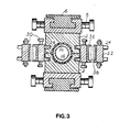
- Fig. 3 is a section along line III-III of Fig. 1;
- Fig. 4 is a section exploded along line IV-IV of Fig. 1.
- Referring now to the drawings, the apparatus of the present invention includes two trains of
moldblock halves 2 driven in an endless paths by means of sprockets 4 engaged withroller pins 5 of thehalves 2. The paths have straight forward (6) and return (8) runs andsemi-circumferential guide tracks 10 and 12 for transferring thehalves 2 between theruns halves 2 are adjacent to each other in theruns run 6 to form a travelling mold for the producedthermoplastic pipe 14 extruded from apipe die 16. - It should be mentioned that the above design corresponds basically to the corrugator described in my U.S. patent No. 4,504,206.
- The straight
forward runs 6 is provided with an upstreamly locatedseries yokes 22 havingshanks 24 for engagement along the travelling mold withcomplimentary recesses 26 made in thehalves 2. Theyokes 22 are provided withrollers 30. - The
series sections paths - It is clearly understood that a person skilled in the art could apply the same structure with different options. For example, the shanks can be conical or cylindrical, can belong to the halves (in which case the complimentary recesses are made in the yokes), the upstream and/or downstream sections can be provided with a rotary transfer (shown as a
sprocket 44 in Fig. 4), the series can be represented by a chain, etc. - In operation, an extrudate of the thermoplastic material flows from the die 16 into the travelling mold. The hydraulic pressure of the melt acting to separate the
halves 2 in therun 6 is accepted byyokes 22 engaged with therecesses 26 in theforward section 36, no forces being transferred farther the halves. Thepaths shanks 24 in the upstream anddownstream sections recesses 26 in a progressive motion without changing their orientation. This allows to avoid mutual undercutting of the shanks and recesses. - Although the present apparatus is directed mostly to externally ribbed pipes production (the process being close to injection molding), in rare cases the apparatus may be applied to withstand the blow pressure in blow molding of extremely large pipes.
- While there has been described and pointed out the fundamental novel feature of the invention as applied to the preferred embodiment, it is to be understood that this description is exemplary and explanatory, but not restrictive, the invention being not limited to the specific details shown and described. Various departures, omissions, substitutions and changes may be made by the skilled in the art without departing from the scope of the invention and without sacrificing its chief advantages. Obviously, many modifications and variations of the present invention are possible in light of the above teaching. It is therefore to be understood that within the scope of the appended claims, the present invention may be practiced otherwise than as specifically described herein.
Claims (4)
a pipe die for extruding a parison of a thermoplastic material;
moldblock halves circulating in an endless path containing a straight forward run wherein the halves cooperate with each other in the directions of their circulation and perpendicularly to the latter, to form a travelling mold for the thermoplastic pipe, a return run and two semi-circumferential guide tracks for transferring the halves between said runs;
a means for withstanding the hydraulic pressure of molding acting to separate the halves in the straight forward run in said perpendicular direction;
the improvement, wherein in order to avoid high loads and wear in said forward run, said means is represented by two endless series of circulating yokes having shanks for engagement along said travelling mold with complimentary recesses made in the halves.
a pipe die for extruding a parison of a thermoplastic material;
moldblock halves circulating in an endless path containing a straight forward run wherein the halves cooperate with each other in the directions of their circulation and perpendicularly to the latter, to form a travelling mold for the thermoplastic pipe, a return run and two semi-circumferential guide tracks for transferring the halves between said runs;
a means for withstanding the hydraulic pressure of molding acting to separate the halves in the straight forward run in both said directions, the means being represented by two endless series of circulating yokes having shanks for engagement along said travelling mold with complimentary recesses made in the halves.
Applications Claiming Priority (2)
| Application Number | Priority Date | Filing Date | Title |
|---|---|---|---|
| US06/849,850 US4681526A (en) | 1986-04-09 | 1986-04-09 | Apparatus for molding thermoplastic pipes |
| US849850 | 1986-04-09 |
Publications (2)
| Publication Number | Publication Date |
|---|---|
| EP0240838A2 true EP0240838A2 (en) | 1987-10-14 |
| EP0240838A3 EP0240838A3 (en) | 1988-11-17 |
Family
ID=25306670
Family Applications (1)
| Application Number | Title | Priority Date | Filing Date |
|---|---|---|---|
| EP87104375A Withdrawn EP0240838A3 (en) | 1986-04-09 | 1987-03-25 | Apparatus for molding thermoplastic pipes |
Country Status (10)
| Country | Link |
|---|---|
| US (1) | US4681526A (en) |
| EP (1) | EP0240838A3 (en) |
| JP (1) | JPS62244618A (en) |
| KR (1) | KR900007355B1 (en) |
| CN (1) | CN1008078B (en) |
| AU (1) | AU584793B2 (en) |
| CA (1) | CA1228705A (en) |
| DE (1) | DE240838T1 (en) |
| NO (1) | NO871480L (en) |
| SU (1) | SU1508950A3 (en) |
Cited By (2)
| Publication number | Priority date | Publication date | Assignee | Title |
|---|---|---|---|---|
| DE4224514A1 (en) * | 1992-07-24 | 1994-01-27 | Wilhelm Hegler | Device for producing a plastic tube with cross-profiling |
| GB2309005B (en) * | 1994-11-07 | 1998-06-17 | Mark Alexander Jenkins | Manufacture of resilient corrugated or convoluted tubing |
Families Citing this family (18)
| Publication number | Priority date | Publication date | Assignee | Title |
|---|---|---|---|---|
| FI73385C (en) * | 1986-03-24 | 1987-10-09 | Uponor Nv | Method and apparatus for making pipes. |
| US4789322A (en) * | 1987-11-23 | 1988-12-06 | Harry Chan | Corrugator with intermeshing overlapping moldblock halves |
| FI80234C (en) * | 1988-07-05 | 1990-05-10 | Uponor Nv | Apparatus for the manufacture of lattice structures |
| US4911633A (en) * | 1988-08-15 | 1990-03-27 | Comfort Gordon A | Apparatus for plastic tubing manufacture |
| CA1298450C (en) * | 1988-09-16 | 1992-04-07 | Manfred A. A. Lupke | Suction applying molded blocks in pipe forming apparatus |
| US5516482A (en) * | 1991-06-14 | 1996-05-14 | Corma Inc. | Travelling mold tunnel apparatus for smooth walled pipe |
| DE4204041C2 (en) * | 1992-02-12 | 1994-03-03 | 2 H Kunststoff Gmbh | Method for producing a built-in element for heat exchanger, mass exchanger and / or bioreactor systems and device for carrying out the method |
| US5257924A (en) * | 1992-06-19 | 1993-11-02 | Cullom Machine Tool & Die, Inc. | Plastic tile corrugator |
| US5489201A (en) * | 1993-04-15 | 1996-02-06 | Cullom Machine Tool & Die, Inc. | Plastic tile corrugator and mold blocks |
| US5545369A (en) * | 1993-09-08 | 1996-08-13 | Corma, Inc. | Clamshell corrugators and the like |
| US6193496B1 (en) * | 1999-03-01 | 2001-02-27 | Cullom Machine Tool & Die, Inc. | Molding machine with mold block carriage |
| US6833103B2 (en) * | 2002-02-11 | 2004-12-21 | Salflex Polymers Ltd. | Pressless blow molding |
| AU2006316231B2 (en) * | 2005-11-16 | 2012-07-12 | Manufacturing Systems Limited | Improvements in or relating to forming apparatus |
| KR100868573B1 (en) * | 2008-06-10 | 2008-11-13 | 원진테크 주식회사 | Apparatus for forming of pvc combine duct |
| CN102126295B (en) * | 2010-01-13 | 2013-06-05 | 深圳成霖洁具股份有限公司 | Production method of integrated plastic water outlet pipe and product thereof |
| CN102241123B (en) * | 2010-05-11 | 2015-04-01 | 上海金纬管道设备制造有限公司 | Braking device for plastic corrugated pipe forming machine |
| DE102015115827B3 (en) | 2015-09-18 | 2017-02-16 | Unicor Gmbh | Device for producing plastic pipes |
| CN105904706B (en) * | 2016-05-23 | 2018-11-20 | 陈真华 | For forming the high-precision modeling machine of medical ultrathin blowpipe |
Citations (3)
| Publication number | Priority date | Publication date | Assignee | Title |
|---|---|---|---|---|
| DE1479172A1 (en) * | 1962-12-06 | 1970-02-26 | Frieseke & Hoepfner Gmbh | Device for conveying and shaping profiled extruded material made of thermoplastic material on screw extrusions |
| US3776679A (en) * | 1970-12-11 | 1973-12-04 | Hegler Wilhelm | Apparatus for the manufacture of plastic tubing of special cross-sectional configuration |
| EP0007556B1 (en) * | 1978-07-22 | 1981-09-09 | Wilhelm Hegler | Apparatus for producing transversely grooved thermoplastic tubes |
Family Cites Families (4)
| Publication number | Priority date | Publication date | Assignee | Title |
|---|---|---|---|---|
| US2866230A (en) * | 1956-02-24 | 1958-12-30 | Pullman Vacuum Cleaner Corp | Corrugated rubber tubing and its production |
| US3280430A (en) * | 1965-05-24 | 1966-10-25 | Acme Hamilton Mfg Corp | Apparatus for making corrugated plastic tubing |
| US3981663A (en) * | 1973-09-10 | 1976-09-21 | Lupke Gerd Paul Heinrich | Apparatus for making high speed corrugated plastic tubing |
| US4504206A (en) * | 1982-01-21 | 1985-03-12 | Lupke Manfred Arno Alfred | Chainless mold drive for a corrugator or the like |
-
1986
- 1986-04-09 US US06/849,850 patent/US4681526A/en not_active Expired - Fee Related
-
1987
- 1987-02-12 CA CA000529540A patent/CA1228705A/en not_active Expired
- 1987-02-14 CN CN87100836A patent/CN1008078B/en not_active Expired
- 1987-03-19 KR KR1019870002516A patent/KR900007355B1/en not_active IP Right Cessation
- 1987-03-25 EP EP87104375A patent/EP0240838A3/en not_active Withdrawn
- 1987-03-25 DE DE198787104375T patent/DE240838T1/en active Pending
- 1987-04-07 JP JP62083940A patent/JPS62244618A/en active Pending
- 1987-04-07 AU AU71140/87A patent/AU584793B2/en not_active Ceased
- 1987-04-08 NO NO871480A patent/NO871480L/en unknown
- 1987-04-08 SU SU874202393A patent/SU1508950A3/en active
Patent Citations (3)
| Publication number | Priority date | Publication date | Assignee | Title |
|---|---|---|---|---|
| DE1479172A1 (en) * | 1962-12-06 | 1970-02-26 | Frieseke & Hoepfner Gmbh | Device for conveying and shaping profiled extruded material made of thermoplastic material on screw extrusions |
| US3776679A (en) * | 1970-12-11 | 1973-12-04 | Hegler Wilhelm | Apparatus for the manufacture of plastic tubing of special cross-sectional configuration |
| EP0007556B1 (en) * | 1978-07-22 | 1981-09-09 | Wilhelm Hegler | Apparatus for producing transversely grooved thermoplastic tubes |
Cited By (4)
| Publication number | Priority date | Publication date | Assignee | Title |
|---|---|---|---|---|
| DE4224514A1 (en) * | 1992-07-24 | 1994-01-27 | Wilhelm Hegler | Device for producing a plastic tube with cross-profiling |
| EP0580984A1 (en) * | 1992-07-24 | 1994-02-02 | Wilhelm Hegler | Apparatus for producing a corrugated plastic pipe |
| US5393211A (en) * | 1992-07-24 | 1995-02-28 | Wilhelm Hegler | Apparatus for the manufacture of a plastic pipe having transverse profile features |
| GB2309005B (en) * | 1994-11-07 | 1998-06-17 | Mark Alexander Jenkins | Manufacture of resilient corrugated or convoluted tubing |
Also Published As
| Publication number | Publication date |
|---|---|
| CN1008078B (en) | 1990-05-23 |
| AU584793B2 (en) | 1989-06-01 |
| US4681526A (en) | 1987-07-21 |
| KR900007355B1 (en) | 1990-10-08 |
| CA1228705A (en) | 1987-11-03 |
| DE240838T1 (en) | 1988-09-01 |
| NO871480L (en) | 1987-10-12 |
| CN87100836A (en) | 1987-10-21 |
| SU1508950A3 (en) | 1989-09-15 |
| KR870009845A (en) | 1987-11-30 |
| AU7114087A (en) | 1987-10-15 |
| EP0240838A3 (en) | 1988-11-17 |
| NO871480D0 (en) | 1987-04-08 |
| JPS62244618A (en) | 1987-10-26 |
Similar Documents
| Publication | Publication Date | Title |
|---|---|---|
| US4681526A (en) | Apparatus for molding thermoplastic pipes | |
| US3776679A (en) | Apparatus for the manufacture of plastic tubing of special cross-sectional configuration | |
| US4325685A (en) | Apparatus for producing thermoplastic tubing having interchangeable mold blocks | |
| US3981663A (en) | Apparatus for making high speed corrugated plastic tubing | |
| US5372774A (en) | Process of and apparatus for making plastic tubing | |
| US3286305A (en) | Apparatus for continuous manufacture of hollow articles | |
| JP3554029B2 (en) | Apparatus for manufacturing corrugated tubes from thermoplastic synthetic resin | |
| US4789322A (en) | Corrugator with intermeshing overlapping moldblock halves | |
| KR970014998A (en) | Apparatus for producing thermoplastic pipes characterized by cross-sectional shape | |
| KR840000358A (en) | Apparatus for manufacturing molded plastic tubes | |
| US3298064A (en) | Apparatus for molding synthetic resin bodies | |
| JPH09511958A (en) | Moving mold with separation of mold block | |
| US5257924A (en) | Plastic tile corrugator | |
| CA2405619A1 (en) | Apparatus for the manufacture of corrugated plastic pipes | |
| CA1057925A (en) | Apparatus for forming plastic tubes using continuous chains of half-dies | |
| AU588457B2 (en) | A method and an apparatus for the production of pipes | |
| IT1214185B (en) | EXTRUDED TOWING DEVICE FOR EXTRUSION PRESS. | |
| SU882761A1 (en) | Apparatus for corrugating plastic tubes | |
| US2189983A (en) | Chain conveyer for heat-treating furnaces | |
| CA1294407C (en) | Corrugator with intermeshing overlapping moldblock halves | |
| KR830001960B1 (en) | Method of producing elements of a slide fastener | |
| DE69007530T2 (en) | Double preform extruder head for multi-layer blow molding. | |
| GB2310186A (en) | Conveyor mat formed from modules | |
| CA2509000A1 (en) | Apparatus for the production of transversely ribbed tubes | |
| MA18932A1 (en) | FLEXIBLE IRRIGATION HOSE AND METHOD AND DEVICE FOR THE PRODUCTION THEREOF |
Legal Events
| Date | Code | Title | Description |
|---|---|---|---|
| PUAI | Public reference made under article 153(3) epc to a published international application that has entered the european phase |
Free format text: ORIGINAL CODE: 0009012 |
|
| AK | Designated contracting states |
Kind code of ref document: A2 Designated state(s): DE FR GB IT NL SE |
|
| ITCL | It: translation for ep claims filed |
Representative=s name: BARZANO' E ZANARDO ROMA S.P.A. |
|
| TCNL | Nl: translation of patent claims filed | ||
| EL | Fr: translation of claims filed | ||
| DET | De: translation of patent claims | ||
| PUAL | Search report despatched |
Free format text: ORIGINAL CODE: 0009013 |
|
| AK | Designated contracting states |
Kind code of ref document: A3 Designated state(s): DE FR GB IT NL SE |
|
| 17P | Request for examination filed |
Effective date: 19890104 |
|
| 17Q | First examination report despatched |
Effective date: 19891012 |
|
| RAP3 | Party data changed (applicant data changed or rights of an application transferred) |
Owner name: LUPKE, MANFRED ARNO ALFRED |
|
| STAA | Information on the status of an ep patent application or granted ep patent |
Free format text: STATUS: THE APPLICATION IS DEEMED TO BE WITHDRAWN |
|
| 18D | Application deemed to be withdrawn |
Effective date: 19900523 |