EP0240989A2 - Multi-screen display control system and its method - Google Patents
Multi-screen display control system and its method Download PDFInfo
- Publication number
- EP0240989A2 EP0240989A2 EP87105133A EP87105133A EP0240989A2 EP 0240989 A2 EP0240989 A2 EP 0240989A2 EP 87105133 A EP87105133 A EP 87105133A EP 87105133 A EP87105133 A EP 87105133A EP 0240989 A2 EP0240989 A2 EP 0240989A2
- Authority
- EP
- European Patent Office
- Prior art keywords
- display
- data
- screen
- bit
- directive
- Prior art date
- Legal status (The legal status is an assumption and is not a legal conclusion. Google has not performed a legal analysis and makes no representation as to the accuracy of the status listed.)
- Granted
Links
Images


Classifications
-
- G—PHYSICS
- G09—EDUCATION; CRYPTOGRAPHY; DISPLAY; ADVERTISING; SEALS
- G09G—ARRANGEMENTS OR CIRCUITS FOR CONTROL OF INDICATING DEVICES USING STATIC MEANS TO PRESENT VARIABLE INFORMATION
- G09G5/00—Control arrangements or circuits for visual indicators common to cathode-ray tube indicators and other visual indicators
- G09G5/14—Display of multiple viewports
Definitions
- the present invention relates to United States Patent Application Serial No. 895,848 and European Patent Application No. 86,111,187.0, entitled "Display Control Method for Multi-window System” and applied by H. Iwami et al. on August 12, 1986.
- the present invention relates to a display control apparatus and its method, and in particular to a display control system and its method suitable to the control of a multi-window system capable of displaying a plurality of windows overlapped on one screen.
- Each of a plurality of windows in the multi-window display is provided with an order of its display on one screen.
- a window provided with a higher order is displayed at the front side with respect to the operator, while a window provided with a lower order is displayed at depths.
- a multi-window administration scheme as described in Japanese Patent Laid-Open No. JP-A-58-168142, for example, is known.
- the function of carrying out display over a plurality of windows in parallel to the display of drawing elements or segments within the multi-window or the function of displaying at high speed the state of an object moving from a window to another window is not mentioned.
- an object of the present invention is to provide a control system and a control method of overlapping multi-window display capable of rapidly moving drawing elements or segments over windows or displaying the movement locus of a drawing element between windows independently of the display control of respective windows.
- Another object of the present invention is to provide a multi-window control system and its method capable of establishing logical planes used by an application program as display regions completely independent of overlapping multi-window display and capable of moving rapidly drawing elements without being conscious of collision between displays.
- a further object of the present invention is to provide a multi-screen control capable of erasing rapidly the current display contents by the second display writing operation.
- a further object of the present invention is to provide a display control system making it unnecessary to redevelop drawing elements or segments for moving rapidly drawing elements.
- a logical plane which is independent of respective windows representing the multi-window display and which has the same size as that of the physical screen, and a buffer for holding a drawing element command supplied via exclusive OR gates on the logic plane.
- the exclusive OR logic operation is carried out while the drawing element command held in the buffer is executed. Further, the exclusive OR logic operation is carried out while the drawing element command held in the above described buffer is carried out again.
- the present logical plane operates independently of respective windows.
- the drawing directive is supplied to the logical plane and a picture is drawn via the exclusive OR gate.
- the drawing element can be moved at high speed.
- Fig. la is a concept diagram for illustrating an embodiment of the present invention.
- One or more logical display spaces 3a-l, 3a-2 and 3b (hereafter referred to as virtual screens) are assigned to each business content of application programs la and lb shown in Fig. la.
- This virtual screen corresponds to a physical display screen for an application program in a conventional display control apparatus consisting of a single program and a single screen.
- the operation for writing data from the application programs la and lb onto each display space and the operation for reading data from each display space to the business program la and lb are possible.
- each virtual screen has an arbitrary size with respect to a real screen 6 (hereafter referred to a physical display screen).
- each window is a rectangular region defined by specifying the position coordinates of the upper left corner point of the window and the length of the window in x and y directions.
- each of these view ports is a rectangular region defined by specifying the position coordinates of the upper left corner point of the view port.
- View ports can be defined so as to allow overlapping of a plurality of view ports. Accordingly, a view port belonging to a lower layer is displayed on the physical display screen 6 with a part thereof being missing.
- a transfer data screen 77 is provided as a region of a logical plane for allowing it to freely draw a picture on the physical display screen 6 independently of the view ports 7a-l, 7a-2 and 7b corresponding to respective virtual screens 3a-l, 3a-2 and 3b.
- a picture can be drawn at high speed on the physical display screen 6 via the exclusive OR operation independently of other view ports 7 by using the logic plane 77. The operation is shown in Fig. lb and will be described later in detail.
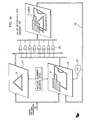
- Fig. 2 is a block diagram for illustrating the configuration of an embodiment of a display control apparatus according to the present invention.
- Each block represents a logic block circuit or a data buffer.
- Each of application programs la and lb supplies definition of virtual screens 3a-l, 3a-2 and 3b, corresponding windows 4a-l, 4a-2 and 4b, and view ports 7a-1, 7a-2 and 7b to virtual terminal control sections 8a and 8b having memories corresponding to virtual screens.
- graphic data such as characters, circles or linear lines, or external picture data inputted by the application program are written onto a virtual screen via the virtual terminal control section segment by segment.
- the virtual screen is administrated by the virtual terminal control section.
- the virtual terminal control section In order to administrate the details of segment data on the virtual screen, the virtual terminal control section generates information concerning respective segments in addition to the displayed data on the virtual screen as the data common to a real terminal control section 9.
- the information generated includes attributes such as the position on the virtual screen, size, transparency/opacity and character space, classification of character/graphic/picture data, classification of solid line/broken line, and the display priority.
- the real terminal control section 9 derives the information for defining the window 4 and the view port 7 defined by the business program 1.
- the real terminal control section 9 generates a display screen administration table 10 which will be described later.
- the real terminal control section 9 extracts the information required for developing on the physical display screen 6 out of the segment data on respective virtual screens 3 segment by segment. Depending upon which virtual screen 3 the drawing directive is destined for, the real terminal control section 9 generates an entry number for indicating the particular view port 7 on the basis of the rectangular region information on the administration table 10. On the basis of this entry number, a display order for each view port is indicated. Portions of view ports of lower ranks are lost due to overlapping.
- the bit map processor control section 12 On the basis of the segment data and the entry number, the bit map processor control section 12 generates a command stream in a display screen buffer 13. The command stream directs a bit map processor to display which part of which view port on which part of the physical screen. At this time, the bit map processor control section 12 loads the character pattern corresponding to the character code contained in each segment of the character/graphic data onto the display screen buffer 13. For the physical display screen 6 of a full dot memory 23 developed on a CRT 15, the bit map processor control section 12 establishes a drawable region, i.e., a region on the physical display screen where a picture can be drawn, on the basis of the rectangular region information stored in the administration table 10. Thus the bit map processor control section 12 establishes a command in the display screen buffer 13.
- a drawable region i.e., a region on the physical display screen where a picture can be drawn
- the command includes the specification of the drawing position of the character/graphic/picture data in a two dimensional coordinate system having the upper left corner of the full dot memory 23 as the origin.
- a command including the size, developing direction, and character code or pattern number of each character region is stored in the buffer 13.
- a command including the vector command, shading pattern and marker pattern is stored in the buffer 13.
- a command including the MH/MR compressed code data of CCITT and its rectangular region size is stored in the buffer 13.
- the bit map processor 14 interpretes the command sequence contained in the buffer 13, judges whether the dots should be included in the drawable region when the character/graphic/picture data is developed into dots, and carries out clipping processing for leaving only the portions included in the drawable region.
- An input device control section 19 traps as an interrupt the data input trigger supplied from physical input devices of a code input unit 16 such as a keyboard and a pointing device 17 such as a mouth.
- the input device control section 19 sets the data set in a hardware register 18 into a code data input buffer 20 and a pointing data input buffer 21.
- the input system is thus driven.
- the contents of the code data input buffer 20 and the pointing data input buffer 21 are read out by the real terminal control section 9 and sorted there into input data to the application program 1 and data for directing the display screen control.
- the real terminal control section 9 judges which is now the virtual screen 3 corresponding to the view port 7 located on the top layer of the display screen, and stores the pertinent input data into one of the virtual input data buffers 22a-l, 22a-2 and 22b administered by the virtual terminal control section 8 corresponding to the pertinent virtual screen 3.
- This input data stored in the virtual input data buffer 22 is reported by the virtual terminal control section 8 to the application program 1 as the answer to the readout request sent from the application program 1 to the virtual terminal control section 8.
- the application program 1 updates the contents of the virtual screen 3 in response to the pertinent input data.
- the drawing elements of each segment 30 are specified from the relative position coordinates of either the upper left corner point or the lower left corner point of the segment in a two dimensional coordinate system having the upper left corner point of the screen 77 (preferably having the same size as the physical display screen 6 and) having the upper left corner point as the origin.
- a command for generating the drawing element data within each segment 30 is held in a transfer data screen buffer 137 to draw a picture on the physical display screen 6 or move a picture at high speed by using the screen 77.
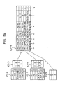
- Figs. 5a and 5b show the contents of the display screen administration table 10 in the real terminal control section 9.
- This administration table is mentioned in the United States Patent Application Serial No. 895,848 and the corresponding European Patent Application No. 86,111,187. 0.
- the real terminal control section 9 sorts the information defining the view port 7 as a rectangular region on the physical display screen 6 into the x and y directions as the positional coordinates of respective sides of each rectangular region, and holds the information thus sorted together with the corresponding view port identifier (tables 10-1 and 10-2).
- tables 10-1 and 10-2 When the x and y directions are seen independently between sets of two entries of tables 10-1 and 10-2 having consecutive entry values (such as entries 1 and 2, and entries 2 and 3), view port identifiers existing in the region range indicated by the two-valued entry are held (tables 10-3 and 10-4).
- the view ports 7 are overlapped, as many view port identifiers as the overlaps are stored. Apart from that, the information representing the overlap priority of the view port 7 at that time is stored in a table 10-5.
- a main table 10-6 of the current display screen administration table 10 is generated as follows.
- the set of two consecutive values contained in the table 10-1 (such as entries 1 and 2, and entries 2 and 3) are selected as one body. If the corresponding entry of the table 10-3 singly holds only a view port identifier, all of the entries containing the same view port identifier among the entries of the table 10 - 4 are searched.
- the corresponding y coordinates are derived from the table 10-2. If, in any case, the entries of the table 10-4 satisfying the search condition are consecutive, they are put together to derive the y coordinate.
- Each entry of the table 10-6 represents a rectangular region on the physical display screen 6.
- n (where n is an integer) virtual screens 3 can be simultaneously displayed on the physical display screen 6 by using the display screen administration table 10 described by referring to Figs. 5a and 5b and the real terminal control section 9.
- the virtual terminal control section 8 is able to direct to draw a picture on an individual window 4 without being conscious of the mutual relation with other windows at all.
- the real terminal control section 9 carries out alteration of the display state of the physical display screen such as alteration of the overlap order of the view ports 7 or the alteration of the size of the view ports 7 by referring to the administration table 10.
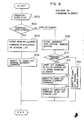
- Fig. 4 shows the table configuration for administrating the drawing elements within the segment 30 directed to be drawn on the screen 77 of Fig. 3 by a command held in the transfer data screen buffer 137.
- the bit map processor control section 12 assures an unused buffer portion within the transfer data screen buffer 137.
- the contents of the requested drawing elements are copied from the input data buffer onto the unused buffer portion and are queued in a stream list 46.
- This exclusive OR stream list 46 administers the buffer portions in use.
- a command stream list 44 of the bit map processor 14 for administering the display screen buffer 13 has levels 1 to 4, for example, on the order of display priority.
- command streams are roughly classified into drawing commands for windows 4 of respective virtual screens 3 and drawing commands for the transfer data screen 77.
- the real terminal control section 9 issues a drawing command to the screen 77, it provides the top of the command stream for the bit map processor control section 12 with a transfer data screen identifier.
- a virtual screen identifier or No. is provided.
- the bit map processor control section 12 sorts the command stream into the transfer data screen buffer 137 or the display screen buffer 13 on the basis of the virtual screen identifier. The command stream is thus stored.
- the bit map processor 14 carries out the exclusive OR stream list 46 surely once before or after it executes a processing request 42 of the command stream list 44 of the level 2 to 4.
- One figure is prevented from being buried into another figure.
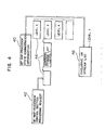
- Fig. 6 is a flow chart of the real terminal control section 9 for realizing the transfer data screen, which has the same size as the physical screen and which is capable of displaying completely independently, on a multi-window. Processing carried out when a drawing directive is issued to the transfer data screen is shown in Fig. 6.
- the drawing directive is issued to the real terminal control section 9 (step 600), it is judged on the basis of the identifier whether the directive is destined for a window which is a virtual terminal or destined for the transfer data screen (step 602). If the result is a request for the transfer data screen .77, a command of the segment or drawing element is additively stored in the exclusive OR stream list 46 (step 604). When the drawing element command has been executed by using the exclusive OR operation, a picture is drawn on the screen 77 (step 606).
- the drawing directive command is stored into the buffer 22 of the virtual screen 3 (step 608).
- the command within the exclusive OR stream list is executed (step 612).
- the drawing element drawn on the screen is erased and the drawing directive command is executed (step 614).
- a command in the exclusive OR stream list 46 is executed (step 616). Drawing on the window 4 is thus completed without disturbing drawing on the screen 77.
- the drawing element command is simply executed (step 618).
- the present embodiment makes it possible to establish a logical plane completely independently of multiple windows which can be overlapped and which are used as display regions by each business program. Without being conscious of collision of displays, therefore, the drawing element can be moved at high speed. Further, it becomes possible to represent the locus of the frame when the frame of the window is drawn on the transfer data screen and the size of the frame is gradually changed in display to the operator. It is also possible to represent the locus obtained when the drawing element is moved from the window to a different rectangular display region.
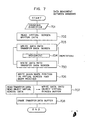
- Fig. 7 shows the program for displaying the process of an image gradually moving between windows of virtual screens.
- this program the appearance and disappearance of the image caused by writing data into the transfer data screen twice (703, 704) and appropriate movement of the image (704) are repeated.
Abstract
Description
- The present invention relates to United States Patent Application Serial No. 895,848 and European Patent Application No. 86,111,187.0, entitled "Display Control Method for Multi-window System" and applied by H. Iwami et al. on August 12, 1986.
- The present invention relates to a display control apparatus and its method, and in particular to a display control system and its method suitable to the control of a multi-window system capable of displaying a plurality of windows overlapped on one screen.
- In a work station operating under the multi-task environment, for example, multiple windows which can be overlapped are used. Each of a plurality of windows in the multi-window display is provided with an order of its display on one screen. A window provided with a higher order is displayed at the front side with respect to the operator, while a window provided with a lower order is displayed at depths.
- A multi-window administration scheme as described in Japanese Patent Laid-Open No. JP-A-58-168142, for example, is known. However, the function of carrying out display over a plurality of windows in parallel to the display of drawing elements or segments within the multi-window or the function of displaying at high speed the state of an object moving from a window to another window is not mentioned.
- The above described prior art has problems that the data movement between multiple windows is not taken into account and the display control extending over windows is impossible.
- Therefore, an object of the present invention is to provide a control system and a control method of overlapping multi-window display capable of rapidly moving drawing elements or segments over windows or displaying the movement locus of a drawing element between windows independently of the display control of respective windows.
- Another object of the present invention is to provide a multi-window control system and its method capable of establishing logical planes used by an application program as display regions completely independent of overlapping multi-window display and capable of moving rapidly drawing elements without being conscious of collision between displays.
- A further object of the present invention is to provide a multi-screen control capable of erasing rapidly the current display contents by the second display writing operation.
- A further object of the present invention is to provide a display control system making it unnecessary to redevelop drawing elements or segments for moving rapidly drawing elements.
- In order to achieve the above described objects, there are disposed a logical plane which is independent of respective windows representing the multi-window display and which has the same size as that of the physical screen, and a buffer for holding a drawing element command supplied via exclusive OR gates on the logic plane. Upon the drawing directive issued on respective windows, the exclusive OR logic operation is carried out while the drawing element command held in the buffer is executed. Further, the exclusive OR logic operation is carried out while the drawing element command held in the above described buffer is carried out again.
- Since the display control is automatically carried out, the present logical plane operates independently of respective windows. When data are to be moved between windows or the drawing directive is issued beyond a window, therefore, the drawing directive is supplied to the logical plane and a picture is drawn via the exclusive OR gate. As a result, the drawing element can be moved at high speed.
-
- Fig. la is a concept diagram for illustrating the control of an overlapped display region which is an embodiment of the present invention.
- Figs. lb and lc show the generation of exclusive OR data between bit map data.
- Fig. 2 is a block diagram for illustrating the configuration of a display control apparatus.
- Fig. 3 shows the administration method of the transfer data screen.
- Fig. 4 is a diagram for illustrating the table configuration of Fig. 3.
- Figs. 5a and 5b are diagrams for illustrating the display screen administration table.
- Figs. 6 and 7 are flow charts for illustrating the processing of a real terminal control section.
- An embodiment of the present invention will now be described in detail by referring to drawings.
- Fig. la is a concept diagram for illustrating an embodiment of the present invention. One or more
logical display spaces 3a-l, 3a-2 and 3b (hereafter referred to as virtual screens) are assigned to each business content of application programs la and lb shown in Fig. la. This virtual screen corresponds to a physical display screen for an application program in a conventional display control apparatus consisting of a single program and a single screen. As indicated byarrows 2, the operation for writing data from the application programs la and lb onto each display space and the operation for reading data from each display space to the business program la and lb are possible. In general, each virtual screen has an arbitrary size with respect to a real screen 6 (hereafter referred to a physical display screen). If it is impossible to develop all of virtual screens on thephysical display screen 6 at one time, it is made possible to define smaller display regions 4a-l, 4a-2 and 4b (hereafter referred to as windows) as regions actually displayed on each virtual screen in order to simultaneously develop contents of respective parts of a plurality ofvirtual screens 3a-l, 3a-2 and 3b. A plurality of windows can be defined for one virtual screen. In a two dimensional coordinate system having the upper left corner point as the origin, each window is a rectangular region defined by specifying the position coordinates of the upper left corner point of the window and the length of the window in x and y directions. These windows are mapped into rectangular regions (hereafter referred to as view ports) 7a-l, 7a-2 and 7b on thephysical display screen 6 and the contents are displayed. As indicated byarrows 5, those rectangular regions 7a-l, 7a-2 and 7b correspond in size and the number to the windows in one to one relationship. In a two dimensional coordinate system having the upper left corner point as the origin, each of these view ports is a rectangular region defined by specifying the position coordinates of the upper left corner point of the view port. View ports can be defined so as to allow overlapping of a plurality of view ports. Accordingly, a view port belonging to a lower layer is displayed on thephysical display screen 6 with a part thereof being missing. - For the display on such a
physical display screen 6, atransfer data screen 77 is provided as a region of a logical plane for allowing it to freely draw a picture on thephysical display screen 6 independently of the view ports 7a-l, 7a-2 and 7b corresponding to respectivevirtual screens 3a-l, 3a-2 and 3b. In order to patch data displayed within a view port with data displayed within another view port, for example, a picture can be drawn at high speed on thephysical display screen 6 via the exclusive OR operation independently ofother view ports 7 by using thelogic plane 77. The operation is shown in Fig. lb and will be described later in detail. - Fig. 2 is a block diagram for illustrating the configuration of an embodiment of a display control apparatus according to the present invention. Each block represents a logic block circuit or a data buffer. At first, the display system shown in the upper right portion of Fig. 2 will now be described. Each of application programs la and lb supplies definition of
virtual screens 3a-l, 3a-2 and 3b, corresponding windows 4a-l, 4a-2 and 4b, and view ports 7a-1, 7a-2 and 7b to virtualterminal control sections 8a and 8b having memories corresponding to virtual screens. Thereafter, graphic data such as characters, circles or linear lines, or external picture data inputted by the application program are written onto a virtual screen via the virtual terminal control section segment by segment. The virtual screen is administrated by the virtual terminal control section. The display system is thus started. In order to administrate the details of segment data on the virtual screen, the virtual terminal control section generates information concerning respective segments in addition to the displayed data on the virtual screen as the data common to a realterminal control section 9. The information generated includes attributes such as the position on the virtual screen, size, transparency/opacity and character space, classification of character/graphic/picture data, classification of solid line/broken line, and the display priority. Via the virtualterminal control section 8a or 8b, the realterminal control section 9 derives the information for defining thewindow 4 and theview port 7 defined by thebusiness program 1. On the basis of the information thus derived, the realterminal control section 9 generates a display screen administration table 10 which will be described later. By using this administration table 10, the realterminal control section 9 extracts the information required for developing on thephysical display screen 6 out of the segment data on respectivevirtual screens 3 segment by segment. Depending upon whichvirtual screen 3 the drawing directive is destined for, the realterminal control section 9 generates an entry number for indicating theparticular view port 7 on the basis of the rectangular region information on the administration table 10. On the basis of this entry number, a display order for each view port is indicated. Portions of view ports of lower ranks are lost due to overlapping. - On the basis of the segment data and the entry number, the bit map
processor control section 12 generates a command stream in a display screen buffer 13. The command stream directs a bit map processor to display which part of which view port on which part of the physical screen. At this time, the bit mapprocessor control section 12 loads the character pattern corresponding to the character code contained in each segment of the character/graphic data onto the display screen buffer 13. For thephysical display screen 6 of afull dot memory 23 developed on aCRT 15, the bit mapprocessor control section 12 establishes a drawable region, i.e., a region on the physical display screen where a picture can be drawn, on the basis of the rectangular region information stored in the administration table 10. Thus the bit mapprocessor control section 12 establishes a command in the display screen buffer 13. The command includes the specification of the drawing position of the character/graphic/picture data in a two dimensional coordinate system having the upper left corner of thefull dot memory 23 as the origin. In case of character data, a command including the size, developing direction, and character code or pattern number of each character region is stored in the buffer 13. In case of graphic data, a command including the vector command, shading pattern and marker pattern is stored in the buffer 13. In case of picture data, a command including the MH/MR compressed code data of CCITT and its rectangular region size is stored in the buffer 13. Thebit map processor 14 interpretes the command sequence contained in the buffer 13, judges whether the dots should be included in the drawable region when the character/graphic/picture data is developed into dots, and carries out clipping processing for leaving only the portions included in the drawable region. - The input system located at the lower right portion of Fig. 2 will now be described. An input device control section 19 traps as an interrupt the data input trigger supplied from physical input devices of a
code input unit 16 such as a keyboard and a pointing device 17 such as a mouth. The input device control section 19 sets the data set in ahardware register 18 into a code data input buffer 20 and a pointingdata input buffer 21. The input system is thus driven. The contents of the code data input buffer 20 and the pointingdata input buffer 21 are read out by the realterminal control section 9 and sorted there into input data to theapplication program 1 and data for directing the display screen control. On the basis of the input data sorted into the drawable region information of the display screen table and theapplication program 1, the realterminal control section 9 judges which is now thevirtual screen 3 corresponding to theview port 7 located on the top layer of the display screen, and stores the pertinent input data into one of the virtual input data buffers 22a-l, 22a-2 and 22b administered by the virtualterminal control section 8 corresponding to the pertinentvirtual screen 3. This input data stored in the virtual input data buffer 22 is reported by the virtualterminal control section 8 to theapplication program 1 as the answer to the readout request sent from theapplication program 1 to the virtualterminal control section 8. Theapplication program 1 updates the contents of thevirtual screen 3 in response to the pertinent input data. - How to administrate the data on the
transfer data screen 77 will now be described by referring to Figs. lb and 3. By using thetransfer data screen 77, it is possible to draw freely a picture on thephysical display screen 6 inpendently of a plurality ofview ports 7 on thephysical display screen 6. In the same way as the data on othervirtual screens 3, all of the data on thescreen 77 are administered while taking the segment indicated by 30 as unit. On thescreen 77, a plurality of segments are so disposed as to allow the overlap. The drawing elements of eachsegment 30 are specified from the relative position coordinates of either the upper left corner point or the lower left corner point of the segment in a two dimensional coordinate system having the upper left corner point of the screen 77 (preferably having the same size as thephysical display screen 6 and) having the upper left corner point as the origin. Independently of the drawing elements within theview port 7 which is a visual portion of eachvirtual screen 3, a command for generating the drawing element data within eachsegment 30 is held in a transferdata screen buffer 137 to draw a picture on thephysical display screen 6 or move a picture at high speed by using thescreen 77. - Figs. 5a and 5b show the contents of the display screen administration table 10 in the real
terminal control section 9. This administration table is mentioned in the United States Patent Application Serial No. 895,848 and the corresponding European Patent Application No. 86,111,187. 0. - The real
terminal control section 9 sorts the information defining theview port 7 as a rectangular region on thephysical display screen 6 into the x and y directions as the positional coordinates of respective sides of each rectangular region, and holds the information thus sorted together with the corresponding view port identifier (tables 10-1 and 10-2). When the x and y directions are seen independently between sets of two entries of tables 10-1 and 10-2 having consecutive entry values (such asentries entries 2 and 3), view port identifiers existing in the region range indicated by the two-valued entry are held (tables 10-3 and 10-4). In a region where theview ports 7 are overlapped, as many view port identifiers as the overlaps are stored. Apart from that, the information representing the overlap priority of theview port 7 at that time is stored in a table 10-5. - By using the information stored in the tables 10-1 to 10-5, a main table 10-6 of the current display screen administration table 10 is generated as follows. The set of two consecutive values contained in the table 10-1 (such as
entries entries 2 and 3) are selected as one body. If the corresponding entry of the table 10-3 singly holds only a view port identifier, all of the entries containing the same view port identifier among the entries of the table 10-4 are searched. The corresponding y coordinates are derived from the table 10-2. If, in any case, the entries of the table 10-4 satisfying the search condition are consecutive, they are put together to derive the y coordinate. - From the x and y coordinates thus derived, one entry of the table 10-6 is produced. By using this, the overlap order of each
view port 7 is administered. Each entry of the table 10-6 represents a rectangular region on thephysical display screen 6. And two x coordinates a and b (such as x coordinates xi and x2 corresponding to theentry 1 of the table 10-3), two y coordinates c and d (such as y coordinates y1 and y1 + y 1 corresponding to theentries 1 to 3 of the table 10-4), length e in the x direction (derived as e = b - a), length f in the y direction (derived as f = d - c), and the corresponding view port identifier g are held. - The correspondence between the
virtual screen 3 and thephysical display screen 6 has been described before. In the present embodiment, n (where n is an integer)virtual screens 3 can be simultaneously displayed on thephysical display screen 6 by using the display screen administration table 10 described by referring to Figs. 5a and 5b and the realterminal control section 9. The virtualterminal control section 8 is able to direct to draw a picture on anindividual window 4 without being conscious of the mutual relation with other windows at all. In addition, the realterminal control section 9 carries out alteration of the display state of the physical display screen such as alteration of the overlap order of theview ports 7 or the alteration of the size of theview ports 7 by referring to the administration table 10. - Fig. 4 shows the table configuration for administrating the drawing elements within the
segment 30 directed to be drawn on thescreen 77 of Fig. 3 by a command held in the transfer data screenbuffer 137. When the request to display the drawing elements of thesegment 30 on thescreen 77 is issued from the realterminal control section 9, the bit mapprocessor control section 12 assures an unused buffer portion within the transfer data screenbuffer 137. The contents of the requested drawing elements are copied from the input data buffer onto the unused buffer portion and are queued in astream list 46. This exclusive ORstream list 46 administers the buffer portions in use. Acommand stream list 44 of thebit map processor 14 for administering the display screen buffer 13 haslevels 1 to 4, for example, on the order of display priority. - These command streams are roughly classified into drawing commands for
windows 4 of respectivevirtual screens 3 and drawing commands for thetransfer data screen 77. When the realterminal control section 9 issues a drawing command to thescreen 77, it provides the top of the command stream for the bit mapprocessor control section 12 with a transfer data screen identifier. In case of the drawing directive for other virtual screens, a virtual screen identifier or No. is provided. Upon receiving the command stream, the bit mapprocessor control section 12 sorts the command stream into the transfer data screenbuffer 137 or the display screen buffer 13 on the basis of the virtual screen identifier. The command stream is thus stored. - If a drawing directive is issued to the
virtual screen 3 to move the drawing element on thevirtual screen 3, thebit map processor 14 carries out the exclusive ORstream list 46 surely once before or after it executes aprocessing request 42 of thecommand stream list 44 of thelevel 2 to 4. A portion of a display segment within thephysical display screen 6 of Fig. lb overlapping display segment B within thetransfer data screen 77 is displayed as represented by C = AB as a result of exclusive OR operation: black (1) + black (1) = white (0) carried out by an exclusive OR
circuit 78. One figure is prevented from being buried into another figure. Fig. lb shows the figure obtained as a result of exclusive OR operation AB = C in case of monochrome. In the operation for color display using R, G and B, the color of the overlapped portion of figures having the same color can be replaced by the complementary color. In this case, three exclusive OR circuits are disposed for each picture element to derive the operation data C = A e B. Whichever data is fed back to the memory of the
physical display screen 6 via a line orbus 79 to be displayed on aCRT 15 instead of previous display data A. - When a drawing element or a segment of the
segments 30 on thescreen 77 is to-be erased, the pertinent segment is searched in the exclusive ORstream list 46, and an indicator for representing the erase is written onto the buffer in thepertinent stream list 46. For the command having the erase indicator set to the erase state, the exclusive OR stream is executed. For the data AB and data B representing figures of Fig. lc, addition (A B)
B) B = A is carried out to derive
data 79 with a triangle B deleted. When all erase indicators of commands of the pertinent exclusive ORstream list 46 has turned to erase states, the pertinent exclusive ORstream list 46 is released. - When elements drawn on
individual windows 4 are moved between windows, the demand for drawing the locus of the movement can be realized by drawing an element on a logic plane called "transfer data screen" which is disposed on the physical screen independently ofrespective windows 4. - Fig. 6 is a flow chart of the real
terminal control section 9 for realizing the transfer data screen, which has the same size as the physical screen and which is capable of displaying completely independently, on a multi-window. Processing carried out when a drawing directive is issued to the transfer data screen is shown in Fig. 6. - When the drawing directive is issued to the real terminal control section 9 (step 600), it is judged on the basis of the identifier whether the directive is destined for a window which is a virtual terminal or destined for the transfer data screen (step 602). If the result is a request for the transfer data screen .77, a command of the segment or drawing element is additively stored in the exclusive OR stream list 46 (step 604). When the drawing element command has been executed by using the exclusive OR operation, a picture is drawn on the screen 77 (step 606).
- If the result of judgment at the
step 602 is a request to thewindow 4, the drawing directive command is stored into the buffer 22 of the virtual screen 3 (step 608). On the basis of an identifier stored in the display screen administration table 10 so as to represent the presence/absence of the transfer data, it is then judged whether the drawing element is being displayed on the screen 77 (step 610). In case of presence, the command within the exclusive OR stream list is executed (step 612). The drawing element drawn on the screen is erased and the drawing directive command is executed (step 614). Thereafter, a command in the exclusive ORstream list 46 is executed (step 616). Drawing on thewindow 4 is thus completed without disturbing drawing on thescreen 77. When the drawing element is absent on thescreen 77, the drawing element command is simply executed (step 618). - Owing to the above described control, it is possible to issue a drawing directive to the application program sending the drawing request to the
window 4 without being conscious of the drawing element of thetransfer data screen 77. Further, it is possible to freely issue a drawing directive request of thescreen 77 from theapplication program 1 or the realterminal control section 9 regardless of the display states of other windows. - In a display apparatus for realizing the multi-task of simultaneously displaying a plurality of businesses, the present embodiment makes it possible to establish a logical plane completely independently of multiple windows which can be overlapped and which are used as display regions by each business program. Without being conscious of collision of displays, therefore, the drawing element can be moved at high speed. Further, it becomes possible to represent the locus of the frame when the frame of the window is drawn on the transfer data screen and the size of the frame is gradually changed in display to the operator. It is also possible to represent the locus obtained when the drawing element is moved from the window to a different rectangular display region.
- Fig. 7 shows the program for displaying the process of an image gradually moving between windows of virtual screens. In this program, the appearance and disappearance of the image caused by writing data into the transfer data screen twice (703, 704) and appropriate movement of the image (704) are repeated.
Claims (9)
Applications Claiming Priority (2)
| Application Number | Priority Date | Filing Date | Title |
|---|---|---|---|
| JP79919/86 | 1986-04-09 | ||
| JP61079919A JPH0766317B2 (en) | 1986-04-09 | 1986-04-09 | Display control method |
Publications (3)
| Publication Number | Publication Date |
|---|---|
| EP0240989A2 true EP0240989A2 (en) | 1987-10-14 |
| EP0240989A3 EP0240989A3 (en) | 1990-01-17 |
| EP0240989B1 EP0240989B1 (en) | 1995-02-22 |
Family
ID=13703704
Family Applications (1)
| Application Number | Title | Priority Date | Filing Date |
|---|---|---|---|
| EP87105133A Expired - Lifetime EP0240989B1 (en) | 1986-04-09 | 1987-04-07 | Multi-screen display control system and its method |
Country Status (4)
| Country | Link |
|---|---|
| US (1) | US4914607A (en) |
| EP (1) | EP0240989B1 (en) |
| JP (1) | JPH0766317B2 (en) |
| DE (1) | DE3751075T2 (en) |
Cited By (1)
| Publication number | Priority date | Publication date | Assignee | Title |
|---|---|---|---|---|
| EP0431618A2 (en) * | 1989-12-06 | 1991-06-12 | Kabushiki Kaisha Toshiba | Method and apparatus for multiwindow display with enhanced window manipulation facilities |
Families Citing this family (53)
| Publication number | Priority date | Publication date | Assignee | Title |
|---|---|---|---|---|
| JP2569072B2 (en) * | 1987-09-21 | 1997-01-08 | 株式会社日立製作所 | Command processing method and apparatus in multi-window system |
| US5313227A (en) * | 1988-04-15 | 1994-05-17 | International Business Machines Corporation | Graphic display system capable of cutting out partial images |
| US5117496A (en) * | 1988-05-23 | 1992-05-26 | Hewlett-Packard Company | Method for recording and replaying mouse commands by recording the commands and the identities of elements affected by the commands |
| US5121478A (en) * | 1988-09-08 | 1992-06-09 | Xerox Corporation | Window system with independently replaceable window functionality |
| US5025396A (en) * | 1989-03-21 | 1991-06-18 | International Business Machines Corporation | Method and apparatus for merging a digitized image with an alphanumeric character string |
| US5353393A (en) * | 1989-06-14 | 1994-10-04 | Sunwest Trading Corporation | Apparatus and method for manipulating scanned documents in a computer aided design system |
| JP3168570B2 (en) * | 1989-11-08 | 2001-05-21 | 富士通株式会社 | Icon pattern automatic generation apparatus and method |
| US5367680A (en) * | 1990-02-13 | 1994-11-22 | International Business Machines Corporation | Rendering context manager for display adapters supporting multiple domains |
| JP2622011B2 (en) * | 1990-04-16 | 1997-06-18 | 三菱電機株式会社 | Screen switching method |
| US5220646A (en) * | 1990-04-30 | 1993-06-15 | International Business Machines Corporation | Single pass hidden line removal using z-buffers |
| US5283860A (en) * | 1990-11-15 | 1994-02-01 | International Business Machines Corporation | System and method for displaying trimmed surfaces using bitplane masking |
| US5379215A (en) * | 1991-02-25 | 1995-01-03 | Douglas P. Kruhoeffer | Method for creating a 3-D image of terrain and associated weather |
| US5448264A (en) * | 1991-03-15 | 1995-09-05 | Hewlett-Packard Company | Method and apparatus for separate window clipping and display mode planes in a graphics frame buffer |
| US5592678A (en) * | 1991-07-23 | 1997-01-07 | International Business Machines Corporation | Display adapter supporting priority based functions |
| US5233686A (en) * | 1991-09-24 | 1993-08-03 | Ceridian Corporation | Open systems software backplane architecture for federated execution of independent application programs |
| US5396597A (en) * | 1992-04-03 | 1995-03-07 | International Business Machines Corporation | System for transferring data between processors via dual buffers within system memory with first and second processors accessing system memory directly and indirectly |
| JPH0651738A (en) * | 1992-07-27 | 1994-02-25 | Canon Inc | Information display device of computer system |
| US5305431A (en) * | 1992-08-18 | 1994-04-19 | International Business Machines Corporation | Method and system for rendering polygons on a raster display |
| JP2583003B2 (en) * | 1992-09-11 | 1997-02-19 | インターナショナル・ビジネス・マシーンズ・コーポレイション | Image display method, frame buffer, and graphics display system in graphics display system |
| CA2109681C (en) * | 1993-03-10 | 1998-08-25 | Donald Edgar Blahut | Method and apparatus for the coding and display of overlapping windows with transparency |
| DE69412479T2 (en) * | 1993-05-10 | 1999-04-22 | Apple Computer | WINDOW SYSTEM WITH INDEPENDENT WINDOWS FOR ELIMINATING GRIDING EFFECTS |
| US5638501A (en) * | 1993-05-10 | 1997-06-10 | Apple Computer, Inc. | Method and apparatus for displaying an overlay image |
| US5487145A (en) * | 1993-07-09 | 1996-01-23 | Taligent, Inc. | Method and apparatus for compositing display items which minimizes locked drawing areas |
| US5526481A (en) * | 1993-07-26 | 1996-06-11 | Dell Usa L.P. | Display scrolling system for personal digital assistant |
| DE69323196T2 (en) * | 1993-09-14 | 1999-09-09 | Ibm | Computer system and method for performing multiple tasks |
| US5522020A (en) * | 1993-09-14 | 1996-05-28 | International Business Machines Corporation | System and method for rapidly determining relative rectangle position |
| US5522025A (en) * | 1993-10-25 | 1996-05-28 | Taligent, Inc. | Object-oriented window area display system |
| JP3611593B2 (en) * | 1994-02-14 | 2005-01-19 | 日本オプネクスト株式会社 | Method for fabricating semiconductor optical device |
| US5812112A (en) * | 1996-03-27 | 1998-09-22 | Fluke Corporation | Method and system for building bit plane images in bit-mapped displays |
| US6052648A (en) * | 1996-04-12 | 2000-04-18 | Earthwatch Communications, Inc. | Method and system for display of weather-related information |
| US6002403A (en) * | 1996-04-30 | 1999-12-14 | Sony Corporation | Graphical navigation control for selecting applications on visual walls |
| US5745109A (en) * | 1996-04-30 | 1998-04-28 | Sony Corporation | Menu display interface with miniature windows corresponding to each page |
| US6043818A (en) * | 1996-04-30 | 2000-03-28 | Sony Corporation | Background image with a continuously rotating and functional 3D icon |
| CA2251124A1 (en) * | 1996-04-30 | 1997-11-06 | George Cossey | User interface for navigating among, organizing and executing program, files and data in a computer system |
| WO1997041547A1 (en) * | 1996-04-30 | 1997-11-06 | Sony Electronics Inc. | Display control method and apparatus |
| US5983291A (en) * | 1996-09-24 | 1999-11-09 | Cirrus Logic, Inc. | System for storing each of streams of data bits corresponding from a separator thereby allowing an input port accommodating plurality of data frame sub-functions concurrently |
| US5929868A (en) * | 1996-09-27 | 1999-07-27 | Apple Computer, Inc. | Method and apparatus for computer display memory management |
| JPH10333631A (en) * | 1997-06-02 | 1998-12-18 | Daichiyuu Denshi:Kk | Expanded display device, and display system using expanded display device |
| WO2001015127A1 (en) * | 1999-08-19 | 2001-03-01 | Deep Video Imaging Limited | Display method for multiple layered screens |
| US7505046B1 (en) * | 2000-05-02 | 2009-03-17 | Adobe Systems Incorporated | Preserving opaque-like rendering in transparent 2D graphics using knockout groups |
| US7901289B2 (en) * | 2001-08-09 | 2011-03-08 | Igt | Transparent objects on a gaming machine |
| US6887157B2 (en) * | 2001-08-09 | 2005-05-03 | Igt | Virtual cameras and 3-D gaming environments in a gaming machine |
| US7909696B2 (en) | 2001-08-09 | 2011-03-22 | Igt | Game interaction in 3-D gaming environments |
| US8002623B2 (en) * | 2001-08-09 | 2011-08-23 | Igt | Methods and devices for displaying multiple game elements |
| US8267767B2 (en) | 2001-08-09 | 2012-09-18 | Igt | 3-D reels and 3-D wheels in a gaming machine |
| US7367885B2 (en) * | 2001-08-09 | 2008-05-06 | Igt | 3-D text in a gaming machine |
| US9189467B1 (en) | 2001-11-07 | 2015-11-17 | Apple Inc. | Method and apparatus for annotating an electronic document |
| US7918730B2 (en) * | 2002-06-27 | 2011-04-05 | Igt | Trajectory-based 3-D games of chance for video gaming machines |
| US8384710B2 (en) * | 2007-06-07 | 2013-02-26 | Igt | Displaying and using 3D graphics on multiple displays provided for gaming environments |
| JP4342578B2 (en) * | 2007-07-24 | 2009-10-14 | 株式会社エヌ・ティ・ティ・ドコモ | Information processing apparatus and program |
| US9092128B2 (en) | 2010-05-21 | 2015-07-28 | Apple Inc. | Method and apparatus for managing visual information |
| KR20140142863A (en) * | 2013-06-05 | 2014-12-15 | 한국전자통신연구원 | Apparatus and method for providing graphic editors |
| KR102449090B1 (en) * | 2018-03-05 | 2022-09-30 | 삼성전자주식회사 | Display apparatus for managing allocation of window buffer and controlling method thereof |
Citations (2)
| Publication number | Priority date | Publication date | Assignee | Title |
|---|---|---|---|---|
| EP0095618A2 (en) * | 1982-05-31 | 1983-12-07 | Kabushiki Kaisha Toshiba | Memory system |
| EP0145817A1 (en) * | 1983-12-19 | 1985-06-26 | International Business Machines Corporation | A data display system |
Family Cites Families (10)
| Publication number | Priority date | Publication date | Assignee | Title |
|---|---|---|---|---|
| JPS58168142A (en) * | 1982-03-30 | 1983-10-04 | Fujitsu Ltd | Managing system of multiplex screen |
| US4545070A (en) * | 1982-04-30 | 1985-10-01 | Fuji Electric Company, Ltd. | Pattern discriminator |
| US4598384A (en) * | 1983-04-22 | 1986-07-01 | International Business Machines Corp. | Graphics display with improved window organization |
| JPS6061794A (en) * | 1983-09-14 | 1985-04-09 | シャープ株式会社 | Personal computer |
| US4542376A (en) * | 1983-11-03 | 1985-09-17 | Burroughs Corporation | System for electronically displaying portions of several different images on a CRT screen through respective prioritized viewports |
| JPS60135989A (en) * | 1983-12-26 | 1985-07-19 | 株式会社日立製作所 | Display area mapping system |
| US4714918A (en) * | 1984-04-30 | 1987-12-22 | International Business Machines Corporation | Window view control |
| JPS6118036A (en) * | 1984-07-04 | 1986-01-25 | Nec Corp | Document correction system |
| JPS61190385A (en) * | 1985-02-20 | 1986-08-25 | 富士通株式会社 | Multi-window display system for display unit |
| US4710767A (en) * | 1985-07-19 | 1987-12-01 | Sanders Associates, Inc. | Method and apparatus for displaying multiple images in overlapping windows |
-
1986
- 1986-04-09 JP JP61079919A patent/JPH0766317B2/en not_active Expired - Lifetime
-
1987
- 1987-04-07 EP EP87105133A patent/EP0240989B1/en not_active Expired - Lifetime
- 1987-04-07 DE DE3751075T patent/DE3751075T2/en not_active Expired - Fee Related
- 1987-04-08 US US07/035,982 patent/US4914607A/en not_active Expired - Lifetime
Patent Citations (2)
| Publication number | Priority date | Publication date | Assignee | Title |
|---|---|---|---|---|
| EP0095618A2 (en) * | 1982-05-31 | 1983-12-07 | Kabushiki Kaisha Toshiba | Memory system |
| EP0145817A1 (en) * | 1983-12-19 | 1985-06-26 | International Business Machines Corporation | A data display system |
Non-Patent Citations (1)
| Title |
|---|
| COMPUTER DESIGN, vol. 21, no. 6, June 1983, pages 54-60, Winchester, Massachussetts, US; "Graphics terminal uses bit-slice processor to offload host computer" * |
Cited By (3)
| Publication number | Priority date | Publication date | Assignee | Title |
|---|---|---|---|---|
| EP0431618A2 (en) * | 1989-12-06 | 1991-06-12 | Kabushiki Kaisha Toshiba | Method and apparatus for multiwindow display with enhanced window manipulation facilities |
| EP0431618A3 (en) * | 1989-12-06 | 1991-10-23 | Kabushiki Kaisha Toshiba | Method and apparatus for multiwindow display with enhanced window manipulation facilities |
| US5430838A (en) * | 1989-12-06 | 1995-07-04 | Kabushiki Kaisha Toshiba | Method and apparatus for multi-window display with enhanced window manipulation facilities |
Also Published As
| Publication number | Publication date |
|---|---|
| DE3751075T2 (en) | 1995-08-31 |
| US4914607A (en) | 1990-04-03 |
| EP0240989A3 (en) | 1990-01-17 |
| DE3751075D1 (en) | 1995-03-30 |
| JPH0766317B2 (en) | 1995-07-19 |
| JPS62237578A (en) | 1987-10-17 |
| EP0240989B1 (en) | 1995-02-22 |
Similar Documents
| Publication | Publication Date | Title |
|---|---|---|
| US4914607A (en) | Multi-screen display control system and its method | |
| EP0121551B1 (en) | Dynamic generation and overlaying of graphic windows for multiple active program storage areas | |
| US5347624A (en) | Method and apparatus for display control | |
| EP0249696B1 (en) | A multiple window display system | |
| EP0180902B1 (en) | Image display apparatus | |
| IE54823B1 (en) | Graphics display method and apparatus | |
| EP0403121A2 (en) | Computer controlled screen animation | |
| GB2059728A (en) | Digital data display system | |
| US5748946A (en) | Method and apparatus for improved graphics picking using auxiliary buffer information | |
| EP0147542B1 (en) | A multiple window display system | |
| CA1323450C (en) | Depth buffer clipping for window management | |
| US4748442A (en) | Visual displaying | |
| EP0162380B1 (en) | Tabulating system | |
| CA1229439A (en) | Data display system | |
| GB2059729A (en) | Multicolour display of digitally processed data | |
| EP0744730A2 (en) | Display device with character masking function | |
| Levy | Vax station: A general-purpose raster graphics architecture | |
| JP3078958B2 (en) | 3D graphic display | |
| Angus | Interactive graphics systems for CAE | |
| JPS63217414A (en) | Graphic display control system | |
| JPH03255520A (en) | Work station device | |
| JPS6249577A (en) | Multi-window priority control system | |
| JPH02232784A (en) | Clipping method and graphic system and work station | |
| JPS61153695A (en) | Character display control system | |
| JPS58146982A (en) | Device for editing document |
Legal Events
| Date | Code | Title | Description |
|---|---|---|---|
| PUAI | Public reference made under article 153(3) epc to a published international application that has entered the european phase |
Free format text: ORIGINAL CODE: 0009012 |
|
| AK | Designated contracting states |
Kind code of ref document: A2 Designated state(s): DE FR GB |
|
| PUAL | Search report despatched |
Free format text: ORIGINAL CODE: 0009013 |
|
| AK | Designated contracting states |
Kind code of ref document: A3 Designated state(s): DE FR GB |
|
| 17P | Request for examination filed |
Effective date: 19900119 |
|
| 17Q | First examination report despatched |
Effective date: 19920729 |
|
| GRAA | (expected) grant |
Free format text: ORIGINAL CODE: 0009210 |
|
| AK | Designated contracting states |
Kind code of ref document: B1 Designated state(s): DE FR GB |
|
| REF | Corresponds to: |
Ref document number: 3751075 Country of ref document: DE Date of ref document: 19950330 |
|
| ET | Fr: translation filed | ||
| PLBE | No opposition filed within time limit |
Free format text: ORIGINAL CODE: 0009261 |
|
| STAA | Information on the status of an ep patent application or granted ep patent |
Free format text: STATUS: NO OPPOSITION FILED WITHIN TIME LIMIT |
|
| 26N | No opposition filed | ||
| REG | Reference to a national code |
Ref country code: GB Ref legal event code: IF02 |
|
| PGFP | Annual fee paid to national office [announced via postgrant information from national office to epo] |
Ref country code: FR Payment date: 20020219 Year of fee payment: 16 |
|
| PGFP | Annual fee paid to national office [announced via postgrant information from national office to epo] |
Ref country code: GB Payment date: 20020328 Year of fee payment: 16 |
|
| PGFP | Annual fee paid to national office [announced via postgrant information from national office to epo] |
Ref country code: DE Payment date: 20020628 Year of fee payment: 16 |
|
| PG25 | Lapsed in a contracting state [announced via postgrant information from national office to epo] |
Ref country code: GB Free format text: LAPSE BECAUSE OF NON-PAYMENT OF DUE FEES Effective date: 20030407 |
|
| PG25 | Lapsed in a contracting state [announced via postgrant information from national office to epo] |
Ref country code: DE Free format text: LAPSE BECAUSE OF NON-PAYMENT OF DUE FEES Effective date: 20031101 |
|
| GBPC | Gb: european patent ceased through non-payment of renewal fee |
Effective date: 20030407 |
|
| PG25 | Lapsed in a contracting state [announced via postgrant information from national office to epo] |
Ref country code: FR Free format text: LAPSE BECAUSE OF NON-PAYMENT OF DUE FEES Effective date: 20031231 |
|
| REG | Reference to a national code |
Ref country code: FR Ref legal event code: ST |