EP0241018A2 - Method of multi-address communication - Google Patents
Method of multi-address communication Download PDFInfo
- Publication number
- EP0241018A2 EP0241018A2 EP87105214A EP87105214A EP0241018A2 EP 0241018 A2 EP0241018 A2 EP 0241018A2 EP 87105214 A EP87105214 A EP 87105214A EP 87105214 A EP87105214 A EP 87105214A EP 0241018 A2 EP0241018 A2 EP 0241018A2
- Authority
- EP
- European Patent Office
- Prior art keywords
- node
- multicast
- frame
- address
- response frame
- Prior art date
- Legal status (The legal status is an assumption and is not a legal conclusion. Google has not performed a legal analysis and makes no representation as to the accuracy of the status listed.)
- Granted
Links
Images


Classifications
-
- H—ELECTRICITY
- H04—ELECTRIC COMMUNICATION TECHNIQUE
- H04L—TRANSMISSION OF DIGITAL INFORMATION, e.g. TELEGRAPHIC COMMUNICATION
- H04L12/00—Data switching networks
- H04L12/02—Details
- H04L12/16—Arrangements for providing special services to substations
- H04L12/18—Arrangements for providing special services to substations for broadcast or conference, e.g. multicast
- H04L12/1863—Arrangements for providing special services to substations for broadcast or conference, e.g. multicast comprising mechanisms for improved reliability, e.g. status reports
- H04L12/1877—Measures taken prior to transmission
-
- H—ELECTRICITY
- H04—ELECTRIC COMMUNICATION TECHNIQUE
- H04L—TRANSMISSION OF DIGITAL INFORMATION, e.g. TELEGRAPHIC COMMUNICATION
- H04L12/00—Data switching networks
- H04L12/28—Data switching networks characterised by path configuration, e.g. LAN [Local Area Networks] or WAN [Wide Area Networks]
- H04L12/42—Loop networks
- H04L12/427—Loop networks with decentralised control
- H04L12/433—Loop networks with decentralised control with asynchronous transmission, e.g. token ring, register insertion
Definitions
- the present invention relates to a method of multi-address communication in a loop network which is formed by connecting a plurality of nodes (namely, communication control devices) each provided with a data processor, to one another through a transmission line, and more particularly to a method of multi-address communication capable of confirming the delivery of multicast information.
- nodes namely, communication control devices
- nodes In a communication system where a plurality of data processors are connected to a bus through communication control devices (thereinafter referred to as "nodes"), to communicate with one another, two communication methods can be used.
- One of the methods is individual communication in which information is sent from a transmitting node to a specified receiving node, and the . other method is multi-address communication in which the same information as transmitted from a transmitting node is received by all the nodes.
- each node is so constructed as to respond to the transmitted information when the node is specified as the receiving node, and the response can be made in two methods.
- an information frame includes a response bit
- the receiving node sets the response bit to a state capable of indicating that the receiving node has succeeded in accepting the information frame.
- the receiving node sends a response frame to the transmitting node when the receiving node receives an information frame transmitted from the transmitting node. The latter method is superior in the reliability of communication information to the former method.
- Fig. 6 shows the construction of a conventional loop transmission system.
- reference characters a , b , c and d designate data processors, and reference numerals 2, 3, 4 and 5 designate nodes.
- the nodes 2 to 5 are connected to one another through a transmission line l, to form a loop network.
- a token passing access method is usually employed.
- Fig. 7 shows a conventional frame format. Referring to Fig.
- a frame is bounded by delimiters l2 and l8, and includes a destination address field l3, a source address field l4, a frame command (or loop command) l5 for indicating the kind of the frame, an information field l6, and a frame check sequence field l7.
- Other frames than an information frame that is, a token frame, a response frame and others do not include the information field l6.
- the response frame is classified into an accept (ACP) frame for indicating the success in accepting an information frame and a busy (BSY) frame for indicating the failure in accepting the information frame due to the busy state of a buffer which is to store the information frame.
- ACP accept
- BSY busy
- Fig. 8 shows a response operation in individual communication which is performed when a receiving node receives an information frame.
- a receiving node receives an information frame.
- the node 4 transmits the ACP or BSY frame to the transmitting node 2.
- the transmitting node 2 transmits a token frame 9 to abandon the transmitting right.
- the response period is predetermined, and hence it is impossible that, in multi-address communication, all the nodes transmit response frames.
- each node having received a multicast information frame l0 does not transmit any response frame.
- the above-mentioned material does not deal with the response method in multi-address communication.
- the conventional communication method cannot inform a transmitting node of the above failure.
- a transmitting node having transmitted a multicast information frame transmits a multicast response frame for the delivery confirmation of the multicast information frame immediately after the transmission of the multicast information frame, and receiving nodes having received the multicast information frame presents information for indicating the reception of the multicast information frame, at the address portion of the multicast response frame, in the order of the node arrangement in a loop network in the direction from the transmitting node toward the down stream thereof, to check the information by the transmitting node and each of the receiving nodes.
- the information for indicating the reception of the multicast information frame may be presented at the source address field or destination address field of the multicast response frame.
- a node having succeeded in accepting the multicast information frame records its own address in the source address field. Accordingly, when each node is informed of the address of the adjacent, upstream node thereof, each node can judge from the multicast response frame whether or not the adjacent, upstream node has succeeded in accepting the multicast information frame.
- the node When a node detects the failure in accepting the multicast information frame by the multicast information frame, the node changes the contents of the loop command of the multicast response frame from "ACP" to "BSY", to inform the transmitting node having transmitted the multicast information frame of the failure in multi-address communication.
- the information for indicating the reception of the multicast information frame is presented at the destination address field of the multicast response frame
- a node having succeeded in accepting the multicast information frame records the address of the adjacent, downstream node in the destination address field.
- the destination address field of the multicast response frame received by the transmitting node contains the address of the transmitting node.
- each of downstream nodes of the above node relays the multicast response frame to the next node while maintaining the address of the node having failed in accepting the multicast information frame, in the destination address field of the multicast response frame, to send such a response frame to the transmitting node, thereby informing the transmitting node of the failure in multi-address communication.
- a transmitting node having transmitted a multicast information frame sets a response period for transmission of a multicast response frame, immediately after the transmission of the multicast information frame, and a receiving node having failed in accepting the multicast information frame transmits a multicast response frame indicative of the failure in accepting the multicast information frame, in the response period.
- the transmitting node receives the above multicast response frame
- the multicast response frame informs the transmitting node of the failure in multi-address communication
- the transmitting node repeats the transmission of the multicast information frame a plurality of times, to succeed in the multi-address communication.
- the transmitting node sets the response period just after the transmission of the multicast information frame.
- the receiving node having failed in accepting the multicast information frame transmits the multicast response frame indicative of the failure in accepting the multicast information frame, in the response period, and the address of the above receiving node and the address of the transmitting node are recorded in the source address field and destination address field of the multicast response frame, respectively.
- each of downstream nodes of the above receiving node can relay the multicast response frame to the next node.
- the transmitting node receives the multicast response frame addressed thereto, the failure in multi-address communication is detected by the transmitting node, and the transmitting node retransmits the multicast information frame.
- the node detects the duplicate transmission of multicast information frame, and neglects the retransmitted information frame to prevent a malfunction in a loop network.
- Figs. l and 2 are timing charts for explaining two embodiments of a method of multi-address communication according to the present invention.
- a transmitting node transmits a multicast information node repeatedly till multi-address communication results in success.
- these embodiments are carried out in the loop network of Fig. 6 using the token passing access method, and frames used in the network have the same format as shown in Fig. 7.
- nodes having received a multicast information frame presents information for indicating the reception of the multicast information frame, at the source address field of a multicast response frame, in the order of node arrangement in the loop network.
- the information for indicating the reception of the multicast information frame is presented at the destination address field of the multicast response frame.
- a node 2 which is requested to transmit a multicast information frame 7 receives a token frame 6, the node 2 acquires the transmitting right, and transmits the multicast information frame 7. Further, the node 2 sets a response period 30 corresponding to l6 octets, to transmit a multicast response frame 20 in the period 30.
- the destination address field, source address field and loop command of the multicast response frame 20 contain a multi-address, the address of the transmitting node 2 and an accept (ACP) pattern, respectively.
- ACP accept
- the node 3 having succeeded in accepting the multicast information frame 7, checks the multicast response frame 20 which follows the multicast information frame 7. The node 3 confirms that the address of the adjacent, upstream node 2 is recorded in the source address field of the multicast response frame 7, and then changes the address recorded in the source address field to the address of the node 3.
- the node 4 having failed in accepting the multicast information frame 7 relays the multicast response frame 20 which follows the multicast information frame 7, to the adjacent, downstream node 5.
- the node 5 having succeeded in accepting the multicast information frame 7 finds that the address recorded in the source address field of the multicast response frame 20 is different from the address of the adjacent, upstream node 4, and thus is informed of the failure in accepting the multicast information node 7 at the node 4. Hence, the node 5 changes the ACP pattern recorded in the loop command of the multicast response frame 20 to the BSY (busy) pattern, to transmit a modified response frame 2l.
- the node 2 having transmitted the multicast information frame 7 receives the modified response frame 2l, the node 2 is informed that multi-address communication has failed at the adjacent, downstream node of the node 3, and carries out predetermined processing.
- the embodiment of Fig. 2 is different from the embodiment of Fig. l in two points, that is, the address information recorded in a multicast response frame which is transmitted from the node 2 immediately after the transmission of the multicast information frame 7, and the processing of the multicast response frame at each receiving node. Accordingly, only the above points will be explained below.
- the node 2 transmits a multicast response frame 22, immediately after having transmitted the multicast information frame 7.
- the destination address field, source address field and loop command of the multicast response frame 22 transmitted from the node 2 contain the address of the adjacent, downstream node 3, the address of the node 2 and the ACP pattern, respectively.
- the node 3 receives the multicast response frame 22, and changes the address recorded in the destination address field of the frame 22 to the address of the adjacent, downstream node 4.
- the node 4 having failed in accepting the multicast information frame 7 relays the multicast response frame 22 to the adjacent, downstream node, that is, the node 5.
- the node 5 finds that the address recorded in the destination address field of the frame 2 is different from the address of the node 5, and hence relays the multicast response frame 22 to the adjacent, downstream node, that is, the node 2.
- the node 2, that is, the transmitting node finds that the address recorded in the destination address field of the frame 22 is not the address of the node 2 but the address of the node 4, and is informed that the multi-address communication has failed at the node 4. Accordingly, the node 2 can carry out predetermined processing.
- Fig. 3 shows a frame transmission/reception control unit which is provided in each node to carry out the embodiments of Figs. l and 2.
- the above control unit operates as follows. Referring to Fig. 3, received data l00 is applied to a synchronizer 8l, to be subjected to synchronizing processing, and then converted by a serial-parallel converter 82 into a 8-bit parallel signal l05, since a fundamental unit made up of eight bits is employed in each field of Fig. 7.
- the received data l00 is self-addressed or multi-addressed
- only the information field of the data is sent to a buffer in a DMA 84 through a received-data processor 83, to be stored in the buffer.
- the frame is aborted on the basis of a signal from an abortion indicating part 96.
- the parallel signal l05 is selected by a second field selector 95, to be relayed to the next node.
- a delay circuit 97 is provided to carry out synchronizing processing necessary for modifying the contents of a desired field.
- the address of an adjacent, upstream node is set in an adjacent node address part 98.
- the address of an adjacent, downstream node is set in the adjacent node address part 98.
- the delay circuit 97 of a node having received a multicast response frame has to delay the parallel signal l05 by two bytes, to modify the contents of the source address field or loop command of the multicast response frame.
- each node contains the address of the adjacent, downstream node. Accordingly, in a case where the embodiment of Fig.
- each node can perform a desired operation by adding only a small number of parts to conventional control unit.
- the embodiment of Fig. 2 also has the following advantage. That is, each node is not required to check the loop command of the multicast response frame, but relays the multicast response frame addressed to a different node, to the next node.
- Fig. 4 is a timing chart for explaining a further embodiment of a method of multi-address communication according to the present invention
- Fig. 5 is a block diagram showing a frame transmission/reception control unit which is provided in each node to carry out the above embodiment.
- the node 2 when the node 2 requested to transmit a multicast information frame l0 receives the token frame 6 to aquire the transmitting right, the node 2 transmits the frame l0, and sets the response period 30 corresponding to l6 octets, in order to be able to transmit a response frame in this period. Then, the node 2 transmits the token frame 9, to abandon the transmitting right.
- the node 3 succeeds in accepting the multicast information frame l0
- the node 4 fails in accepting the frame l0 owing to the busy state of the buffer for the multicast information frame l0.
- the node 3 having succeeded in accepting the multicast information frame l0 does not perform any other operation than the relay of the frame l0.
- the node 4 having failed in accepting the multicast information frame l0 relays the frame l0 to the adjacent, downstream node, and also transmits a multicast response frame ll in the response period 30 which follows the relaying period of the frame l0, to inform the node 2 of the failure in multi-address communication.
- the destination address field, source address field and loop command of the multicast response frame ll contain the address of the node 2, the address of the node 4 and the BSY pattern, respectively.
- the node 5 relays the multicast response frame ll to the node 2.
- the node 2 having received the multicast response frame ll is informed of the failure in the multi-address communication, and acquires the transmitting right by receiving the token frame 9.
- the node 2 sends out a retransmitted version 3l of the multicast information frame l0.
- the node 3 having received the retransmitted information frame 3l detects the duplicate transmission of information frame, and neglects the retransmitted information frame 3l.
- the node 4 accepts the retransmitted information frame 3l, when the buffer is kept at the free state. When the buffer of the node 4 is kept at the busy state, the transmission of the multicast response frame ll and the following operations are repeated, a plurality of times.
- a time necessary for the multicast information frame transmitted from a node to return to the node is monitored, and the same retransmitting operation as mentioned above is performed when the multicast information frame fails to return to the transmitting node within a predetermined period.
- Received data l00 is applied to the synchronizer 8l, to be subjected to synchronizing processing, and then converted by the serial-parallel converter 82 into the 8-bit parallel signal l05.
- the data l00 is self-addressed or multi-addressed data
- only the information field of the received data is sent to a buffer in the DMA 84 through the received-data processor 83, to be stored in the buffer.
- the frame is aborted on the basis of a signal from the abortion indicating part 96.
- the parallel signal l05 is selected by the second field selector 95, to be relayed to the next node.
- a signal l0l from the DMA 84 informs the received-data processor 83 that the buffer is busy, and the transmission controller 87 is actuated to form a multicast response frame.
- the multicast response frame is formed on the basis of a control signal l04 from the transmission controller 87.
- the outputs of a destination address part 88, a source address part 89 and a loop command part 90 which are loaded with predetermined values, and the output of a delimiter generator 9l are selected by a first field selector 94, and the output of the selector 94 and the output of a frame check sequence (FCS) computing part 92 are selected by the second field selector, to form the multicast response frame.
- FCS frame check sequence
- the multicast information frame transmitting flag is recorded in the state controller 86.
- an information field signal l06 from the buffer is selected by the first field selector 94, together with the outputs of the parts 88, 89, 90 and 9l, to form a retransmitted information frame.
- a time necessary for the multicast information to be transmitted from the present control unit to return thereto, is monitored by a timer 85.
- a conventional communication control unit When a conventional communication control unit is additionally provided with the hardware for transmitting a BSY frame at a time the control unit fails in accepting a multicast information frame, and the hardware for checking the BSY frame which follows the multicast information frame, delivery confirmation of transmitted information can be made not only in individual communication but also in the embodiment of Fig. 4.
- the delivery confirmation of a multicast information frame can be made, and moreover the multicast information frame can be retransmitted when multi-address communication results in failure because of the busy state of a buffer. That is, the transmission of the multicast information frame can be surely controlled. Further, even when multi-address communication results in failure because of an error or fault in hardware, the delivery confirmation of a multicast information frame can be made, and thus reliable multi-address communication can be carried out.
Landscapes
- Engineering & Computer Science (AREA)
- Computer Networks & Wireless Communication (AREA)
- Signal Processing (AREA)
- Small-Scale Networks (AREA)
Abstract
Description
- The present invention relates to a method of multi-address communication in a loop network which is formed by connecting a plurality of nodes (namely, communication control devices) each provided with a data processor, to one another through a transmission line, and more particularly to a method of multi-address communication capable of confirming the delivery of multicast information.
- In a communication system where a plurality of data processors are connected to a bus through communication control devices (thereinafter referred to as "nodes"), to communicate with one another, two communication methods can be used. One of the methods is individual communication in which information is sent from a transmitting node to a specified receiving node, and the . other method is multi-address communication in which the same information as transmitted from a transmitting node is received by all the nodes.
- In the individual communication, each node is so constructed as to respond to the transmitted information when the node is specified as the receiving node, and the response can be made in two methods. In one of the methods, an information frame includes a response bit, and the receiving node sets the response bit to a state capable of indicating that the receiving node has succeeded in accepting the information frame. In the other method, the receiving node sends a response frame to the transmitting node when the receiving node receives an information frame transmitted from the transmitting node. The latter method is superior in the reliability of communication information to the former method.
- The latter method is discussed in material paper No. 23 (l984), Working groups for Distributed Processing System in Information Processing Society of Japan, pp. l- 8.
- Fig. 6 shows the construction of a conventional loop transmission system. In Fig. 6, reference characters a, b, c and d designate data processors, and
reference numerals nodes 2 to 5 are connected to one another through a transmission line l, to form a loop network. In this network, a token passing access method is usually employed. Fig. 7 shows a conventional frame format. Referring to Fig. 7, a frame is bounded by delimiters l2 and l8, and includes a destination address field l3, a source address field l4, a frame command (or loop command) l5 for indicating the kind of the frame, an information field l6, and a frame check sequence field l7. Other frames than an information frame, that is, a token frame, a response frame and others do not include the information field l6. The response frame is classified into an accept (ACP) frame for indicating the success in accepting an information frame and a busy (BSY) frame for indicating the failure in accepting the information frame due to the busy state of a buffer which is to store the information frame. - Fig. 8 shows a response operation in individual communication which is performed when a receiving node receives an information frame. Referring to Fig. 8, when an
information frame 7 transmitted from anode 2 which has acquired the transmitting right, is received by anode 4 whose address is recorded in the destination address field of theinformation frame 7, thenode 4 transmits the ACP or BSY frame to the transmittingnode 2. When aresponse period 30 set for response frame has elapsed, the transmittingnode 2 transmits atoken frame 9 to abandon the transmitting right. In the conventionl communication method, the response period is predetermined, and hence it is impossible that, in multi-address communication, all the nodes transmit response frames. Accordingly, in the conventional multi-address communication using the token ring system, as shown in Fig. 9, each node having received a multicast information frame l0 does not transmit any response frame. The above-mentioned material does not deal with the response method in multi-address communication. - As mentioned above, in a case where a node fails in accepting multicast information because of the busy state of a buffer for the multicast information, the conventional communication method cannot inform a transmitting node of the above failure.
- It is a main object of the present invention to provide a method of multi-address communication capable of solving the above problem of the prior art and carrying out delivery confirmation that a transmitting node is informed of the success or failure in accepting information at a receiving node, in multi-address communication as in individual communication. In order to attain the above object, according to one aspect of the present invention, a transmitting node having transmitted a multicast information frame transmits a multicast response frame for the delivery confirmation of the multicast information frame immediately after the transmission of the multicast information frame, and receiving nodes having received the multicast information frame presents information for indicating the reception of the multicast information frame, at the address portion of the multicast response frame, in the order of the node arrangement in a loop network in the direction from the transmitting node toward the down stream thereof, to check the information by the transmitting node and each of the receiving nodes.
- The information for indicating the reception of the multicast information frame may be presented at the source address field or destination address field of the multicast response frame. In a case where the above information is presented at the source address field, a node having succeeded in accepting the multicast information frame records its own address in the source address field. Accordingly, when each node is informed of the address of the adjacent, upstream node thereof, each node can judge from the multicast response frame whether or not the adjacent, upstream node has succeeded in accepting the multicast information frame. When a node detects the failure in accepting the multicast information frame by the multicast information frame, the node changes the contents of the loop command of the multicast response frame from "ACP" to "BSY", to inform the transmitting node having transmitted the multicast information frame of the failure in multi-address communication. In a case where the information for indicating the reception of the multicast information frame is presented at the destination address field of the multicast response frame, a node having succeeded in accepting the multicast information frame records the address of the adjacent, downstream node in the destination address field. Thus, when the multi-address communication results in success, the destination address field of the multicast response frame received by the transmitting node contains the address of the transmitting node. When a node fails in accepting the multicast information frame, each of downstream nodes of the above node relays the multicast response frame to the next node while maintaining the address of the node having failed in accepting the multicast information frame, in the destination address field of the multicast response frame, to send such a response frame to the transmitting node, thereby informing the transmitting node of the failure in multi-address communication.
- Further, according to another aspect of the present invention, a transmitting node having transmitted a multicast information frame sets a response period for transmission of a multicast response frame, immediately after the transmission of the multicast information frame, and a receiving node having failed in accepting the multicast information frame transmits a multicast response frame indicative of the failure in accepting the multicast information frame, in the response period. When the transmitting node receives the above multicast response frame, the multicast response frame informs the transmitting node of the failure in multi-address communication, and the transmitting node repeats the transmission of the multicast information frame a plurality of times, to succeed in the multi-address communication. In more detail, the transmitting node sets the response period just after the transmission of the multicast information frame. Meanwhile, the receiving node having failed in accepting the multicast information frame transmits the multicast response frame indicative of the failure in accepting the multicast information frame, in the response period, and the address of the above receiving node and the address of the transmitting node are recorded in the source address field and destination address field of the multicast response frame, respectively. Thus, each of downstream nodes of the above receiving node can relay the multicast response frame to the next node. When the transmitting node receives the multicast response frame addressed thereto, the failure in multi-address communication is detected by the transmitting node, and the transmitting node retransmits the multicast information frame. When a node having succeeded in accepting the multicast information frame receives the retransmitted information frame, the node detects the duplicate transmission of multicast information frame, and neglects the retransmitted information frame to prevent a malfunction in a loop network.
- The above and the other objects and features of the present invention will become more apparent from the following description taken in conjunction with the accompanying drawings.
-
- Figs. l, 2 and 4 are timing charts for explaining three embodiments of a method of multi-address communication according to the present invention.
- Fig. 3 is a block diagram showing a frame transmission/reception control unit which is provided in each node to carry out the embodiments of Figs. l and 2.
- Fig. 5 is a block diagram showing a frame transmission/reception control unit which is provided in each node to carry out the embodiment of Fig. 4.
- Fig. 6 is a block diagram showing a conventional loop transmission system.
- Fig. 7 is a schematic diagram showing a conventional frame format.
- Figs. 8 and 9 are timing charts for explaining the conventional individual communication and the conventional multi-address communication.
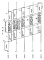
- Figs. l and 2 are timing charts for explaining two embodiments of a method of multi-address communication according to the present invention. In these embodiments, a transmitting node transmits a multicast information node repeatedly till multi-address communication results in success. Further, these embodiments are carried out in the loop network of Fig. 6 using the token passing access method, and frames used in the network have the same format as shown in Fig. 7.
- In the embodiment of Fig. l, nodes having received a multicast information frame presents information for indicating the reception of the multicast information frame, at the source address field of a multicast response frame, in the order of node arrangement in the loop network. Meanwhile, in the embodiment of Fig. 2, the information for indicating the reception of the multicast information frame is presented at the destination address field of the multicast response frame.
- Referring now to Fig. l, when a
node 2 which is requested to transmit amulticast information frame 7, receives atoken frame 6, thenode 2 acquires the transmitting right, and transmits themulticast information frame 7. Further, thenode 2 sets aresponse period 30 corresponding to l6 octets, to transmit amulticast response frame 20 in theperiod 30. The destination address field, source address field and loop command of themulticast response frame 20 contain a multi-address, the address of the transmittingnode 2 and an accept (ACP) pattern, respectively. After having transmitted themulticast response frame 20, thenode 2 transmits anothertoken frame 9, to abandon the transmitting right. - Now, explanation will be made of a case where a
node 3 succeeds in accepting themulticast information frame 7 transmitted from thenode 2, and anode 4 fails in accepting themulticast information frame 7 owing to an error or fault in hardware at thenode 4. - The
node 3 having succeeded in accepting themulticast information frame 7, checks themulticast response frame 20 which follows themulticast information frame 7. Thenode 3 confirms that the address of the adjacent, upstreamnode 2 is recorded in the source address field of themulticast response frame 7, and then changes the address recorded in the source address field to the address of thenode 3. - The
node 4 having failed in accepting themulticast information frame 7 relays themulticast response frame 20 which follows themulticast information frame 7, to the adjacent,downstream node 5. - The
node 5 having succeeded in accepting themulticast information frame 7 finds that the address recorded in the source address field of themulticast response frame 20 is different from the address of the adjacent, upstreamnode 4, and thus is informed of the failure in accepting themulticast information node 7 at thenode 4. Hence, thenode 5 changes the ACP pattern recorded in the loop command of themulticast response frame 20 to the BSY (busy) pattern, to transmit a modified response frame 2l. - When the
node 2 having transmitted themulticast information frame 7 receives the modified response frame 2l, thenode 2 is informed that multi-address communication has failed at the adjacent, downstream node of thenode 3, and carries out predetermined processing. - The embodiment of Fig. 2 is different from the embodiment of Fig. l in two points, that is, the address information recorded in a multicast response frame which is transmitted from the
node 2 immediately after the transmission of themulticast information frame 7, and the processing of the multicast response frame at each receiving node. Accordingly, only the above points will be explained below. - Referring to Fig. 2, the
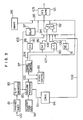
node 2 transmits amulticast response frame 22, immediately after having transmitted themulticast information frame 7. The destination address field, source address field and loop command of themulticast response frame 22 transmitted from thenode 2 contain the address of the adjacent,downstream node 3, the address of thenode 2 and the ACP pattern, respectively. After having received themulticast information frame 7, thenode 3 receives themulticast response frame 22, and changes the address recorded in the destination address field of theframe 22 to the address of the adjacent,downstream node 4. Thenode 4 having failed in accepting themulticast information frame 7 relays themulticast response frame 22 to the adjacent, downstream node, that is, thenode 5. Thenode 5 finds that the address recorded in the destination address field of theframe 2 is different from the address of thenode 5, and hence relays themulticast response frame 22 to the adjacent, downstream node, that is, thenode 2. Thenode 2, that is, the transmitting node finds that the address recorded in the destination address field of theframe 22 is not the address of thenode 2 but the address of thenode 4, and is informed that the multi-address communication has failed at thenode 4. Accordingly, thenode 2 can carry out predetermined processing. - Fig. 3 shows a frame transmission/reception control unit which is provided in each node to carry out the embodiments of Figs. l and 2. The above control unit operates as follows. Referring to Fig. 3, received data l00 is applied to a synchronizer 8l, to be subjected to synchronizing processing, and then converted by a serial-
parallel converter 82 into a 8-bit parallel signal l05, since a fundamental unit made up of eight bits is employed in each field of Fig. 7. In a case where the received data l00 is self-addressed or multi-addressed, only the information field of the data is sent to a buffer in aDMA 84 through a received-data processor 83, to be stored in the buffer. Further, when a received frame is self-addressed, the frame is aborted on the basis of a signal from anabortion indicating part 96. When the data l00 is addressed to another node or multi-addressed, the parallel signal l05 is selected by asecond field selector 95, to be relayed to the next node. - A
delay circuit 97 is provided to carry out synchronizing processing necessary for modifying the contents of a desired field. In a case where the embodiment of Fig. l is carried out, the address of an adjacent, upstream node is set in an adjacentnode address part 98. Meanwhile, in a case where the embodiment of Fig. 2 is carried out, the address of an adjacent, downstream node is set in the adjacentnode address part 98. When a multicast information frame is transmitted from the control unit, a multicast information transmitting flag is recorded in astate controller 86. - In the embodiment of Fig. l, the
delay circuit 97 of a node having received a multicast response frame has to delay the parallel signal l05 by two bytes, to modify the contents of the source address field or loop command of the multicast response frame. Meanwhile, in the embodiment of Fig. 2, it is required to delay the parallel signal l05 by three bytes. That is, the embodiment of Fig. l is smaller in amount of signal delay than the embodiment of Fig. 2, and thus the former embodiment is more advantageous than the latter embodiment. However, in the loop network using the token passing access method, each node contains the address of the adjacent, downstream node. Accordingly, in a case where the embodiment of Fig. 2 is carried out, each node can perform a desired operation by adding only a small number of parts to conventional control unit. The embodiment of Fig. 2 also has the following advantage. That is, each node is not required to check the loop command of the multicast response frame, but relays the multicast response frame addressed to a different node, to the next node. - Fig. 4 is a timing chart for explaining a further embodiment of a method of multi-address communication according to the present invention, and Fig. 5 is a block diagram showing a frame transmission/reception control unit which is provided in each node to carry out the above embodiment.
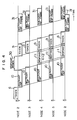
- Referring to Fig. 4, when the
node 2 requested to transmit a multicast information frame l0 receives thetoken frame 6 to aquire the transmitting right, thenode 2 transmits the frame l0, and sets theresponse period 30 corresponding to l6 octets, in order to be able to transmit a response frame in this period. Then, thenode 2 transmits thetoken frame 9, to abandon the transmitting right. Now, explanation will be made of a case where thenode 3 succeeds in accepting the multicast information frame l0, and thenode 4 fails in accepting the frame l0 owing to the busy state of the buffer for the multicast information frame l0. - The
node 3 having succeeded in accepting the multicast information frame l0 does not perform any other operation than the relay of the frame l0. Thenode 4 having failed in accepting the multicast information frame l0 relays the frame l0 to the adjacent, downstream node, and also transmits a multicast response frame ll in theresponse period 30 which follows the relaying period of the frame l0, to inform thenode 2 of the failure in multi-address communication. The destination address field, source address field and loop command of the multicast response frame ll contain the address of thenode 2, the address of thenode 4 and the BSY pattern, respectively. Thenode 5 relays the multicast response frame ll to thenode 2. - The
node 2 having received the multicast response frame ll is informed of the failure in the multi-address communication, and acquires the transmitting right by receiving thetoken frame 9. Thus, thenode 2 sends out a retransmitted version 3l of the multicast information frame l0. Thenode 3 having received the retransmitted information frame 3l detects the duplicate transmission of information frame, and neglects the retransmitted information frame 3l. However, thenode 4 accepts the retransmitted information frame 3l, when the buffer is kept at the free state. When the buffer of thenode 4 is kept at the busy state, the transmission of the multicast response frame ll and the following operations are repeated, a plurality of times. In the present embodiment, a time necessary for the multicast information frame transmitted from a node to return to the node, is monitored, and the same retransmitting operation as mentioned above is performed when the multicast information frame fails to return to the transmitting node within a predetermined period. - Next, explanation will be made of the operation of the control unit of Fig. 5 for carrying out the embodiment of Fig. 4.
- Received data l00 is applied to the synchronizer 8l, to be subjected to synchronizing processing, and then converted by the serial-
parallel converter 82 into the 8-bit parallel signal l05. In a case where the data l00 is self-addressed or multi-addressed data, only the information field of the received data is sent to a buffer in theDMA 84 through the received-data processor 83, to be stored in the buffer. Further, when a received frame is self-addressed one, the frame is aborted on the basis of a signal from theabortion indicating part 96. When the received data is addressed to another node or multi-addressed, the parallel signal l05 is selected by thesecond field selector 95, to be relayed to the next node. - When a multicast information frame is applied to the control unit in a state that the buffer is busy, a signal l0l from the
DMA 84 informs the received-data processor 83 that the buffer is busy, and thetransmission controller 87 is actuated to form a multicast response frame. The multicast response frame is formed on the basis of a control signal l04 from thetransmission controller 87. That is, the outputs of adestination address part 88, asource address part 89 and aloop command part 90 which are loaded with predetermined values, and the output of a delimiter generator 9l are selected by afirst field selector 94, and the output of theselector 94 and the output of a frame check sequence (FCS) computingpart 92 are selected by the second field selector, to form the multicast response frame. - In a case where a multicast information frame has been transmitted from the present control unit, the multicast information frame transmitting flag is recorded in the
state controller 86. In a case where the multicast information frame is retransmitted from the present control unit, an information field signal l06 from the buffer is selected by thefirst field selector 94, together with the outputs of theparts timer 85. - When a conventional communication control unit is additionally provided with the hardware for transmitting a BSY frame at a time the control unit fails in accepting a multicast information frame, and the hardware for checking the BSY frame which follows the multicast information frame, delivery confirmation of transmitted information can be made not only in individual communication but also in the embodiment of Fig. 4.
- As has been explained in the foregoing, according to the present invention, the delivery confirmation of a multicast information frame can be made, and moreover the multicast information frame can be retransmitted when multi-address communication results in failure because of the busy state of a buffer. That is, the transmission of the multicast information frame can be surely controlled. Further, even when multi-address communication results in failure because of an error or fault in hardware, the delivery confirmation of a multicast information frame can be made, and thus reliable multi-address communication can be carried out.
Claims (5)
Applications Claiming Priority (2)
| Application Number | Priority Date | Filing Date | Title |
|---|---|---|---|
| JP82231/86 | 1986-04-11 | ||
| JP61082231A JPS62239641A (en) | 1986-04-11 | 1986-04-11 | Multiple address communication system |
Publications (3)
| Publication Number | Publication Date |
|---|---|
| EP0241018A2 true EP0241018A2 (en) | 1987-10-14 |
| EP0241018A3 EP0241018A3 (en) | 1989-08-30 |
| EP0241018B1 EP0241018B1 (en) | 1993-09-15 |
Family
ID=13768631
Family Applications (1)
| Application Number | Title | Priority Date | Filing Date |
|---|---|---|---|
| EP87105214A Expired - Lifetime EP0241018B1 (en) | 1986-04-11 | 1987-04-08 | Method of multi-address communication |
Country Status (4)
| Country | Link |
|---|---|
| US (1) | US4792947A (en) |
| EP (1) | EP0241018B1 (en) |
| JP (1) | JPS62239641A (en) |
| DE (1) | DE3787393T2 (en) |
Cited By (2)
| Publication number | Priority date | Publication date | Assignee | Title |
|---|---|---|---|---|
| EP0496986A2 (en) * | 1990-12-28 | 1992-08-05 | Symbol Technologies, Inc. | Packet data communication system |
| EP0593918A1 (en) * | 1992-10-20 | 1994-04-27 | Mitsubishi Denki Kabushiki Kaisha | Communication control apparatus |
Families Citing this family (42)
| Publication number | Priority date | Publication date | Assignee | Title |
|---|---|---|---|---|
| JPH0666806B2 (en) * | 1988-02-08 | 1994-08-24 | 住友電気工業株式会社 | Token ring transmission method |
| JPH0773267B2 (en) * | 1988-03-02 | 1995-08-02 | 横河電機株式会社 | Communication control device |
| US5155858A (en) * | 1988-10-27 | 1992-10-13 | At&T Bell Laboratories | Twin-threshold load-sharing system with each processor in a multiprocessor ring adjusting its own assigned task list based on workload threshold |
| US5559962A (en) * | 1989-10-09 | 1996-09-24 | Yamaha Corporation | Data transmission system selecting both source and destination using addressing mechanism |
| US5193152A (en) * | 1989-11-03 | 1993-03-09 | Racal-Datacom, Inc. | Network management system with group naming |
| WO1992013309A1 (en) * | 1991-01-23 | 1992-08-06 | Sun Microsystems, Inc. | Method and apparatus for scoped interprocess message switching |
| US5296936A (en) * | 1991-07-22 | 1994-03-22 | International Business Machines Corporation | Communication apparatus and method for transferring image data from a source to one or more receivers |
| JP2501737B2 (en) * | 1992-02-28 | 1996-05-29 | インターナショナル・ビジネス・マシーンズ・コーポレイション | DATA TRANSFER METHOD AND DEVICE |
| US5280477A (en) * | 1992-08-17 | 1994-01-18 | E-Systems, Inc. | Network synchronous data distribution system |
| US6018771A (en) * | 1992-11-25 | 2000-01-25 | Digital Equipment Corporation | Dynamic assignment of multicast network addresses |
| JP2806466B2 (en) * | 1993-05-17 | 1998-09-30 | 株式会社日立製作所 | Data transmission control method |
| US5544163A (en) * | 1994-03-08 | 1996-08-06 | Excel, Inc. | Expandable telecommunications system |
| EP0695061A1 (en) * | 1994-07-28 | 1996-01-31 | International Business Machines Corporation | Channel allocation method for a ring network |
| US5566178A (en) * | 1994-12-22 | 1996-10-15 | International Business Machines Corporation | Method and system for improving the performance of a token ring network |
| US5860080A (en) * | 1996-03-19 | 1999-01-12 | Apple Computer, Inc. | Multicasting system for selecting a group of memory devices for operation |
| KR100210807B1 (en) * | 1996-12-23 | 1999-07-15 | 유기범 | Apparatus for routing ipc message |
| JPH11308253A (en) * | 1998-04-20 | 1999-11-05 | Honda Motor Co Ltd | Network system |
| US7069340B1 (en) * | 1998-09-18 | 2006-06-27 | British Telecommunications Public Limited Company | System and method for operating a transmitter to multicast data blocks over a network |
| US7469297B1 (en) | 2000-08-04 | 2008-12-23 | Intellon Corporation | Mechanism for using a quasi-addressed response to bind to a message requesting the response |
| US6671284B1 (en) * | 2000-08-04 | 2003-12-30 | Intellon Corporation | Frame control for efficient media access |
| US6987770B1 (en) | 2000-08-04 | 2006-01-17 | Intellon Corporation | Frame forwarding in an adaptive network |
| US7298691B1 (en) | 2000-08-04 | 2007-11-20 | Intellon Corporation | Method and protocol to adapt each unique connection in a multi-node network to a maximum data rate |
| US6907044B1 (en) | 2000-08-04 | 2005-06-14 | Intellon Corporation | Method and protocol to support contention-free intervals and QoS in a CSMA network |
| US7352770B1 (en) | 2000-08-04 | 2008-04-01 | Intellon Corporation | Media access control protocol with priority and contention-free intervals |
| US6909723B1 (en) | 2000-08-04 | 2005-06-21 | Intellon Corporation | Segment bursting with priority pre-emption and reduced latency |
| US8149703B2 (en) | 2002-06-26 | 2012-04-03 | Qualcomm Atheros, Inc. | Powerline network bridging congestion control |
| US7826466B2 (en) | 2002-06-26 | 2010-11-02 | Atheros Communications, Inc. | Communication buffer scheme optimized for VoIP, QoS and data networking over a power line |
| US7120847B2 (en) | 2002-06-26 | 2006-10-10 | Intellon Corporation | Powerline network flood control restriction |
| US7623542B2 (en) | 2002-10-21 | 2009-11-24 | Intellon Corporation | Contention-free access intervals on a CSMA network |
| KR100949020B1 (en) * | 2003-09-22 | 2010-03-23 | 엘지전자 주식회사 | Service method and system for multicast streaming |
| US7281187B2 (en) | 2003-11-20 | 2007-10-09 | Intellon Corporation | Using error checking bits to communicated an address or other bits |
| US8090857B2 (en) | 2003-11-24 | 2012-01-03 | Qualcomm Atheros, Inc. | Medium access control layer that encapsulates data from a plurality of received data units into a plurality of independently transmittable blocks |
| US7660327B2 (en) | 2004-02-03 | 2010-02-09 | Atheros Communications, Inc. | Temporary priority promotion for network communications in which access to a shared medium depends on a priority level |
| US7715425B2 (en) | 2004-02-26 | 2010-05-11 | Atheros Communications, Inc. | Channel adaptation synchronized to periodically varying channel |
| US7636370B2 (en) | 2005-03-03 | 2009-12-22 | Intellon Corporation | Reserving time periods for communication on power line networks |
| US7822059B2 (en) | 2005-07-27 | 2010-10-26 | Atheros Communications, Inc. | Managing contention-free time allocations in a network |
| US8175190B2 (en) | 2005-07-27 | 2012-05-08 | Qualcomm Atheros, Inc. | Managing spectra of modulated signals in a communication network |
| EP2159966A1 (en) | 2007-05-10 | 2010-03-03 | Intellon Corporation | Managing distributed access to a shared medium |
| US8781016B2 (en) | 2010-04-12 | 2014-07-15 | Qualcomm Incorporated | Channel estimation for low-overhead communication in a network |
| US9197428B1 (en) * | 2010-11-24 | 2015-11-24 | Nyse Arca Llc | Methods and apparatus for requesting message gap fill requests and responding to message gap fill requests |
| US9792649B1 (en) | 2010-11-24 | 2017-10-17 | Nyse Arca Llc | Methods and apparatus for performing risk checking |
| US8891605B2 (en) | 2013-03-13 | 2014-11-18 | Qualcomm Incorporated | Variable line cycle adaptation for powerline communications |
Citations (2)
| Publication number | Priority date | Publication date | Assignee | Title |
|---|---|---|---|---|
| EP0093004A2 (en) * | 1982-04-28 | 1983-11-02 | International Computers Limited | Data communication system |
| EP0115761A2 (en) * | 1983-02-03 | 1984-08-15 | International Business Machines Corporation | Method for determining physical order of active stations on a token ring |
Family Cites Families (3)
| Publication number | Priority date | Publication date | Assignee | Title |
|---|---|---|---|---|
| JPS58175335A (en) * | 1982-04-07 | 1983-10-14 | Hitachi Ltd | Loop-back controlling system of loop type data transmission system |
| BE895438A (en) * | 1982-12-22 | 1983-06-22 | Bell Telephone Mfg | COMMUNICATION SYSTEM WITH MULTIPLE RINGS |
| US4593154A (en) * | 1983-07-08 | 1986-06-03 | Nissan Motor Company, Limited | Loop-type data transmission/reception network |
-
1986
- 1986-04-11 JP JP61082231A patent/JPS62239641A/en active Pending
-
1987
- 1987-04-08 DE DE87105214T patent/DE3787393T2/en not_active Expired - Fee Related
- 1987-04-08 EP EP87105214A patent/EP0241018B1/en not_active Expired - Lifetime
- 1987-04-13 US US07/037,848 patent/US4792947A/en not_active Expired - Lifetime
Patent Citations (2)
| Publication number | Priority date | Publication date | Assignee | Title |
|---|---|---|---|---|
| EP0093004A2 (en) * | 1982-04-28 | 1983-11-02 | International Computers Limited | Data communication system |
| EP0115761A2 (en) * | 1983-02-03 | 1984-08-15 | International Business Machines Corporation | Method for determining physical order of active stations on a token ring |
Non-Patent Citations (1)
| Title |
|---|
| AFIPS CONFERENCE PROCEEDINGS 1981 NATIONAL COMPUTER CONFERENCE, Chicago, Illinois, 4th-7th May 1981, pages 209-214, AFIPS Press, Arlington, US; W.Y. CHENG et al.: "Illinet-A 32 Mbits/sec. local-area network" * |
Cited By (4)
| Publication number | Priority date | Publication date | Assignee | Title |
|---|---|---|---|---|
| EP0496986A2 (en) * | 1990-12-28 | 1992-08-05 | Symbol Technologies, Inc. | Packet data communication system |
| EP0496986B1 (en) * | 1990-12-28 | 1998-07-22 | Symbol Technologies, Inc. | Packet data communication system |
| EP0593918A1 (en) * | 1992-10-20 | 1994-04-27 | Mitsubishi Denki Kabushiki Kaisha | Communication control apparatus |
| US5384778A (en) * | 1992-10-20 | 1995-01-24 | Mitsubishi Denki Kabushiki Kaisha | Communication control apparatus |
Also Published As
| Publication number | Publication date |
|---|---|
| DE3787393D1 (en) | 1993-10-21 |
| EP0241018A3 (en) | 1989-08-30 |
| JPS62239641A (en) | 1987-10-20 |
| US4792947A (en) | 1988-12-20 |
| EP0241018B1 (en) | 1993-09-15 |
| DE3787393T2 (en) | 1994-05-11 |
Similar Documents
| Publication | Publication Date | Title |
|---|---|---|
| EP0241018A2 (en) | Method of multi-address communication | |
| EP0359241B1 (en) | Control method for distributed processing system | |
| EP0123507B1 (en) | Data communication system and apparatus | |
| EP0147644B1 (en) | Token ring with secondary transmit opportunities | |
| CA1320547C (en) | Information transmission system having collective data transmission and collection devices | |
| CA1180459A (en) | Distributed data processing in ring-structured networks architected for full duplex peer-to-peer operation of processing stations and uninterruptible transfer of long data records between stations | |
| US4511958A (en) | Common bus access system using plural configuration tables for failure tolerant token passing among processors | |
| US5099346A (en) | Infrared communications network | |
| US4896151A (en) | Simultaneous communication method and system | |
| US4759015A (en) | Ring network system for transmission of multicast information | |
| EP0146831A2 (en) | Message stripping protocol for a ring communication network | |
| EP0228078A2 (en) | Limited multicast communication method and communication network system realizing the method | |
| US4622550A (en) | Data communication system | |
| EP0374883A2 (en) | System for internetwork communication between local area networks | |
| JPH06500903A (en) | Method and apparatus for specifying destination and source addresses in a packet network | |
| US4860000A (en) | Data transmission system using sending right request signal transferred through loop transmission path | |
| EP0093004B1 (en) | Data communication system | |
| EP0276468B1 (en) | Data transmission control method | |
| EP0279627A2 (en) | Communication apparatus | |
| JP3077610B2 (en) | In-device monitoring and control system | |
| US5469446A (en) | Retry filter and circulating echo method and apparatus | |
| JP3466860B2 (en) | Node arrangement order check method for ring network | |
| JPS6342990B2 (en) | ||
| USRE33181E (en) | Data transmission system adapted to facilitate detection of safe receipt of a transmitted data frame by a receiving station | |
| JPH01276844A (en) | Method for confirming multiple address communication response |
Legal Events
| Date | Code | Title | Description |
|---|---|---|---|
| PUAI | Public reference made under article 153(3) epc to a published international application that has entered the european phase |
Free format text: ORIGINAL CODE: 0009012 |
|
| 17P | Request for examination filed |
Effective date: 19870408 |
|
| AK | Designated contracting states |
Kind code of ref document: A2 Designated state(s): DE FR GB |
|
| PUAL | Search report despatched |
Free format text: ORIGINAL CODE: 0009013 |
|
| AK | Designated contracting states |
Kind code of ref document: A3 Designated state(s): DE FR GB |
|
| 17Q | First examination report despatched |
Effective date: 19910904 |
|
| GRAA | (expected) grant |
Free format text: ORIGINAL CODE: 0009210 |
|
| RBV | Designated contracting states (corrected) |
Designated state(s): DE GB |
|
| AK | Designated contracting states |
Kind code of ref document: B1 Designated state(s): DE GB |
|
| REF | Corresponds to: |
Ref document number: 3787393 Country of ref document: DE Date of ref document: 19931021 |
|
| PLBE | No opposition filed within time limit |
Free format text: ORIGINAL CODE: 0009261 |
|
| STAA | Information on the status of an ep patent application or granted ep patent |
Free format text: STATUS: NO OPPOSITION FILED WITHIN TIME LIMIT |
|
| 26N | No opposition filed | ||
| PGFP | Annual fee paid to national office [announced via postgrant information from national office to epo] |
Ref country code: DE Payment date: 19950524 Year of fee payment: 9 |
|
| PGFP | Annual fee paid to national office [announced via postgrant information from national office to epo] |
Ref country code: GB Payment date: 19960329 Year of fee payment: 10 |
|
| PG25 | Lapsed in a contracting state [announced via postgrant information from national office to epo] |
Ref country code: DE Effective date: 19970101 |
|
| PG25 | Lapsed in a contracting state [announced via postgrant information from national office to epo] |
Ref country code: GB Effective date: 19970408 |
|
| GBPC | Gb: european patent ceased through non-payment of renewal fee |
Effective date: 19970408 |