EP0241318B1 - Low voltage distribution system with two-conductor track - Google Patents
Low voltage distribution system with two-conductor track Download PDFInfo
- Publication number
- EP0241318B1 EP0241318B1 EP87303229A EP87303229A EP0241318B1 EP 0241318 B1 EP0241318 B1 EP 0241318B1 EP 87303229 A EP87303229 A EP 87303229A EP 87303229 A EP87303229 A EP 87303229A EP 0241318 B1 EP0241318 B1 EP 0241318B1
- Authority
- EP
- European Patent Office
- Prior art keywords
- track
- adaptor
- casing
- contact
- conductor
- Prior art date
- Legal status (The legal status is an assumption and is not a legal conclusion. Google has not performed a legal analysis and makes no representation as to the accuracy of the status listed.)
- Expired - Lifetime
Links
Images


Classifications
-
- F—MECHANICAL ENGINEERING; LIGHTING; HEATING; WEAPONS; BLASTING
- F21—LIGHTING
- F21V—FUNCTIONAL FEATURES OR DETAILS OF LIGHTING DEVICES OR SYSTEMS THEREOF; STRUCTURAL COMBINATIONS OF LIGHTING DEVICES WITH OTHER ARTICLES, NOT OTHERWISE PROVIDED FOR
- F21V21/00—Supporting, suspending, or attaching arrangements for lighting devices; Hand grips
- F21V21/34—Supporting elements displaceable along a guiding element
- F21V21/35—Supporting elements displaceable along a guiding element with direct electrical contact between the supporting element and electric conductors running along the guiding element
-
- H—ELECTRICITY
- H01—ELECTRIC ELEMENTS
- H01R—ELECTRICALLY-CONDUCTIVE CONNECTIONS; STRUCTURAL ASSOCIATIONS OF A PLURALITY OF MUTUALLY-INSULATED ELECTRICAL CONNECTING ELEMENTS; COUPLING DEVICES; CURRENT COLLECTORS
- H01R25/00—Coupling parts adapted for simultaneous co-operation with two or more identical counterparts, e.g. for distributing energy to two or more circuits
- H01R25/14—Rails or bus-bars constructed so that the counterparts can be connected thereto at any point along their length
- H01R25/142—Their counterparts
Definitions
- This invention relates to a low voltage distribution system with a two-conductor track.
- low voltage is meant fifty volts or less.
- FR-A-2 545 288 discloses an electrical adaptor in combination with a conductor track comprising an outer conductive metal casing, inner metal conductors and insulation supporting the inner metal conductors within the outer metal casing and insulating each conductor electrically from the other conductors and the casing, said outer metal casing, inner metal conductors and insulation all extending continuously along the whole length of the track, both the inner metal conductors and the outer metal casing being exposed for electrical contact therewith to be possible by the adaptor applied to the track anywhere along the length of the track, the casing having two sides between which is an opening along the whole length of the track to give access to the inner conductors for electric current-carrying contact members of the adaptor along the whole length of the track.
- FR-A-2 545 288 the conductors are along both sides of the casing, the drawings of FR-A-2 545 288 showing three conductors (7a) along one side and another three conductors (7b) along the other side, well shielded by insulating material from being accidentally touched.
- Each conductor (7a, 7b) is embedded in the insulating material, pieces of which project laterally inwardly, above and below each conductor. Access to the conductors is only possible by means of a special adaptor.
- DE-A-1 640 482 (INSUL-8-CORP) is equivalent to GB-A-1 151 088, which discloses electric power distribution apparatus comprising a generally flat electrically insulated cable including a plurality of parallel spaced apart conductors which are totally encased in insulation, an elongate U-shaped channel member, having its edges turned in to form lips defining an elongate slot there-between, and adapted to support the cable therewithin so that the conductors lie in a plane transverse to the channel slot, a power plug insertable through said slot in the channel member and having a plurality of sharp metallic prongs spaced apart at locations corresponding to the spaced positions of the conductors for piercing the conductor insulation and contacting respective ones of the conductors at a selected location along the length of the cable, and a clamp adapted to co-operate with a shoulder on the plug whereby to rigidly hold the prongs in contact with the respective conductors, means being provided for preventing penetration of the prongs into the respective
- the invention has for its principal object the provision of a two-conductor track which will take an adaptor anywhere along the track for energising, for example, an electric lamp.
- Another object is to provide an adaptor which will carry a lamp which can be rotated freely on the adaptor without twisting wires connecting the lamp to a rotatable contact assembly of the adaptor.
- Another object is to make the track easily mountable to a support.
- Another object is to provide a power supply connector which incorporates overload protection means.
- the present invention provides an electrical adaptor in combination with a conductor track as claimed in each of Claims 1 to 14, to which reference is directed.
- the illustrated track 10 is a two-conductor track of which one conductor is an outer conductor formed by an extruded aluminium casing 12 and the other conductor is an inner conductor formed by a copper strip 14 which is insulated by insulation 16, the strip 14 being held in place by lips 18 of insulation 16.
- the conductors 12 and 14 and insulation 16 all extend continuously (with uniform cross-sections) along the whole length of the track, the conductors 12 and 14 being exposed for electrical contact therewith by an adaptor 20 applied to the track 10 anywhere along the length of the track.
- the insulation 16 is of extruded plastic, having wings 17 which are held resiliently in place under lips 19 of casing 12.
- the adaptor 20 comprises a plastic insulating body 22 which fits between two sides 24, 24 of the track 10, being somewhat narrower than an integral flat plastic top 25 which abuts the track sides 24, 24.
- Two pairs of resilient cantilever arms 6, 26, 26, 26 extend longitudinally of the body 22 in mutually opposite directions and are integral with the body 22.
- the tip of each arm 26 is formed with an outwardly projecting lip 28 which is interlockingly engageable with a respective one of the lips 19 of casing 12.
- the normal (i.e. unstressed) positions of arms 26 are inward, disengaging lips 28 from lips 19.
- the adaptor 20 For biasing arms 26 outward to interlock lips 28 with lips 19, the adaptor 20 comprises two pivoted members 30 which can be selectively pivoted from the 'open' position of Fig. 2 (for disengagement) to the 'closed' position of Fig. 3 (in which they displace the two pairs of arms 26 apart into interlocking engagement with the track 10), about pivots 32.
- the two members 30 have flat tops 34 which lie flush with the top 25 of the body 22 in the closed position of Fig. 3. It will be appreciated that the space between each pair of arms 26, 26 is 'normally' (i.e. when unstressed) narrower than portion 36 of the respective member 30 which comes between them.
- the adaptor 20 also comprises a rotatable contact assembly 40 which makes electrical contact with the track 10 in any rotational position.
- the contact assembly 40 comprises a sub-assembly 42 (Fig. 2) of an electrical centre contact 44 (to contact the strip 14) and a split sleeve outer electrical contact 46 (to contact the lips 19 of casing 12).
- An insulating plastic grommet (not shown) inside the sleeve contact 46 receives and positions the centre contact 44.
- the sub-assembly 42 also includes two metal connector terminals 48, 50 which are respectively integral with contacts 44, 46. Near where the centre contact 44 engages conductors 14, it is located by a bottom end wall 23 of body 22.
- the contact assembly 40 also comprises, besides the sub-assembly 42, two semi-cylindrical half inner insulating sleeves 52a, 52b, an outer sleeve 54, a bracket 56, two electrical connector terminals 58a, b (respectively crimped to insulation-covered wires 60a, b) and a washer 62.
- the half sleeves 52a, 52b encase the sub-assembly 42; a flange 64 of an upstanding integral boss 66 of body 22 is rotatably received in a circular groove 52c of sleeves 52a, 52b to retain the contact assembly 40 on the body 22.
- the bracket 56 fits over the half sleeves 52a, 52b and has two tongues 56a which engage grooves 52d in half sleeves 52a, b to lock bracket 56 against relative rotation.
- the outer sleeve 54 also fits over half sleeves 52a, b and has tongues 54a engaging grooves 52d to prevent relative rotation.
- the terminals 58a, b fit onto the tags 48, 50, the wires 60a, b extending through the centre hole 54b in the top of the sleeve 54 and through the washer 62.
- the bracket 56 is adapted to support a spot- lamp (not shown) or other illuminating device, to which the wires 60a, b are connected (not shown). Because the entire contact assembly 40 (that is, sub-assembly 42, half-sleeves 52a, b, outer sleeve 54, bracket 56, terminals 58a, b, wires 60a, b and washer 62) rotates as one unit, the wires 60a, b never get twisted, either around themselves or around the bracket 56.
- contacts 44 and 46 are respectively a centre contact and a sleeve contact of annular cross-section (both being coaxial with the axis of rotation) electrical contact is made with copper strip 14 and with the lips 19 of casing 12 respectively in all rotational positions of contact assembly 40.
- the adaptor 20 can be fitted to the track 10 anywhere along its length with the members 30 initially 'open' as shown in Figs. 1 and 2, and locked in position by closing members 30 to the position of Fig. 3 in which arms 26 are displaced positively outwardly to interlock lips 28 with lips 19.
- Fig. 4 illustrates a modified track 70 having a casing 72 of generally rounded, cylindrical configuration, in contrast to the rather angular configuration of casing 12 of track 10.
- the track 70 is similar to track 10.
- a fixing device 74 For mounting the track 10 or the track 70 to a support, referring to Figs. 5 to 8 (which happen to show the modified track 70, with copper strip 14 and insulation 16 shown only in Fig. 6) a fixing device 74 is provided comprising a mounting member 76 mounted rotatably to the (not shown) support (e.g. by a screw 78), and a connecting piece 80 slidingly connected to the back of the casing 72 by means of engaging an undercut tongue 82 of the connecting piece 80 in an undercut groove 84 in casing 72. Laterally projecting wings 86 of connecting piece 80 are received through a rectangular opening 88 in the outside face of mounting member 76, which can then be rotated to retain the wings 86 in recesses 90 in mounting member 76. Since connecting piece 80 is slidable along the casing 72 of track 70, accurate positioning is less critical, making assembly easier.
- the track 10 has an undercut groove (not shown) at the back of it, the same as groove 84 of track 70, and hence can be mounted in the same way.
- the modified track 92 of Fig. 9 differs from the track 70 of Fig. 4 in having two circular cross- sectioned copper rods 94 partly embedded in and extending along the aluminium casing 96.
- the contact 46 of the adaptor 20 engages and makes electrical contact with exposed inner surfaces 98 of the two copper rods 96.
- the track 92 is identical to the track 70.
- FIG. 10 In the modification of Figs. 10 and 11, as compared with the arrangements described hereinabove, like references refer to like parts.
- the above-mentioned plastic grommet (not shown) of adaptor is omitted from the adaptor 20' of Fig. 10.
- the half inner sleeves 52a', 52b' are provided with a cross-partition 100 just below the terminals 58a, 58b as seen in Fig. 10.
- a modified metal connector tag 48', integral with centre contact 44, carries a compression spring 102 which acts between the partition 100 and a bend at 104 in connector tap 48', to bias the contact 44 down onto the conductor strip 14' of track 70 (compare Fig. 4).
- the double track 100 of Fig. 12 comprises two co-extensive, back-to-back tracks 102 and 104.
- Each of the tracks 102, 104 is similar to the above- described tracks of Figs. 1 to 11 apart from the casing shape.
- the two casings are integral, formed by a unitary casing member 106 which is generally H-shaped except that the sides 108, 108 are (,)-shaped, each being outwardly convex.
- the triple track 110 of Fig. 13 comprises three co-extensive, side-by-side tracks 112, 114, 116 with integral casings formed by a unitary casing member 118.
- the track 10 of Fig. 1 could be described as of generally triangular cross-section and the tracks of Figs. 4, 6, 9 and 11 as of generally cylindrical cross-section
- the track of Fig. 13 is generally rectangular in cross-section and has a rear mounting groove 120.
- the two tracks 102, 104 of the double track 100 of Fig. 12 can be separately switched, as can the three tracks 112, 114, 116 of triple track 110 of Fig. 13.
- a track power supply connector 122 incorporates a thermally-activated current-sensitive cut-out device 124 (hereinafter referred to as a thermal cut-out device 124) with a reset button 126 and is adapted to supply electrical power to the track 92 (see also Fig. 9) from a twin-conductor power lead 128.
- a thermally-activated current-sensitive cut-out device 124 hereinafter referred to as a thermal cut-out device 124
- a reset button 126 is adapted to supply electrical power to the track 92 (see also Fig. 9) from a twin-conductor power lead 128.
- a side contact 130 (Figs. 14 to 17) of connector 122 connects conductor 132 of power lead 128 electrically to copper rods 94 of track 92.
- Side contact 130 has a metal ferrule 134 integral with two metal spring contacts 136, 138.
- the ferrule 134 is crimped in well-known manner to conductor 132, having an inner ear 140 to engage conductor 132 itself and an outer ear 142 to engage the insulation of power lead 128.
- the spring contacts 136,138 which are separated by a slot 144, fit springily between conductor rods 94 and engage the side surfaces 98 (Fig. 9) thereof.
- the other conductor 146 of power lead 128 is connected to the input of the thermal cut-out device 124 by a ferrule 148.
- the thermal cut-out device 124 incorporates a mechanism, not illustrated, of well-known type, including a bimetallic strip which carries all the current to the track 92 and which is effective upon excessive current, that uyto say an overload, causing corresponding deflection of the strip, to open a pair of electrical contacts of the mechanism so as to cut off electrical power from the track 92.
- the mechanism is designed for this pair of electrical contacts to remain open until closed (after cooling of the bimetallic strip) upon operation of reset button 126.
- a centre contact 150 (Figs. 14 and 18 to 20) connects the output of the thermal cut-out device 124 to the copper strip 14.
- the centre contact 150 has three spring contacts 152, 154, 156 which press down upon the copper strip 14.
- An insulating partition 158 (Fig. 14) separates ferrule 148 from centre contact 150.
- the connector 122 is provided with a rotary locking cam 160 (Figs. 14 and 21 to 24) comprising a cam head 162 connected integrally to a cross-slotted operating head 164 by a shaft 166.
- the two "ears" of the cam head 162 engage undersides 168 (Fig. 9) of track 92.
- the connector 122 comprises a housing 170 of insulating material that houses the cut-out device 124, contacts 130 and 150 and ferrule 148 and rotatably supports the locking cam 160.
Abstract
Description
- This invention relates to a low voltage distribution system with a two-conductor track. By "low voltage" is meant fifty volts or less.
- FR-A-2 545 288 (PROFILUX SRL) discloses an electrical adaptor in combination with a conductor track comprising an outer conductive metal casing, inner metal conductors and insulation supporting the inner metal conductors within the outer metal casing and insulating each conductor electrically from the other conductors and the casing, said outer metal casing, inner metal conductors and insulation all extending continuously along the whole length of the track, both the inner metal conductors and the outer metal casing being exposed for electrical contact therewith to be possible by the adaptor applied to the track anywhere along the length of the track, the casing having two sides between which is an opening along the whole length of the track to give access to the inner conductors for electric current-carrying contact members of the adaptor along the whole length of the track.
- However, in FR-A-2 545 288, the conductors are along both sides of the casing, the drawings of FR-A-2 545 288 showing three conductors (7a) along one side and another three conductors (7b) along the other side, well shielded by insulating material from being accidentally touched. Each conductor (7a, 7b) is embedded in the insulating material, pieces of which project laterally inwardly, above and below each conductor. Access to the conductors is only possible by means of a special adaptor.
- DE-A-1 640 482 (INSUL-8-CORP) is equivalent to GB-A-1 151 088, which discloses electric power distribution apparatus comprising a generally flat electrically insulated cable including a plurality of parallel spaced apart conductors which are totally encased in insulation, an elongate U-shaped channel member, having its edges turned in to form lips defining an elongate slot there-between, and adapted to support the cable therewithin so that the conductors lie in a plane transverse to the channel slot, a power plug insertable through said slot in the channel member and having a plurality of sharp metallic prongs spaced apart at locations corresponding to the spaced positions of the conductors for piercing the conductor insulation and contacting respective ones of the conductors at a selected location along the length of the cable, and a clamp adapted to co-operate with a shoulder on the plug whereby to rigidly hold the prongs in contact with the respective conductors, means being provided for preventing penetration of the prongs into the respective conductors beyond a predetermined distance.
- The invention has for its principal object the provision of a two-conductor track which will take an adaptor anywhere along the track for energising, for example, an electric lamp.
- Another object is to provide an adaptor which will carry a lamp which can be rotated freely on the adaptor without twisting wires connecting the lamp to a rotatable contact assembly of the adaptor.
- Another object is to make the track easily mountable to a support.
- Another object is to provide a power supply connector which incorporates overload protection means.
- The present invention provides an electrical adaptor in combination with a conductor track as claimed in each of
Claims 1 to 14, to which reference is directed. - The invention will be described by way of example with reference to the accompanying drawings, wherein:-
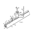
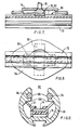
- Fig. 1 illustrates a track and an adaptor;
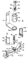
- Fig. 2 is an exploded view of the adaptor;
- Fig. 3 is a section of the track and the adaptor;
- Fig. 4 illustrates a modified track;
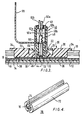
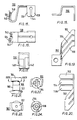
- Fig. 5 illustrates the casing of the modified track and a fixing device, in plan view;
- Figs. 6 and 7 are sections on lines VI-VI and VII-VII respectively of Fig. 5;
- Fig. 8 is an underneath plan view corresponding to Fig. 5;
- Fig. 9 is a cross-section through another modified track;
- Fig. 10 is a section of a track with a modified adaptor;
- Fig. 11 is a cross-section through the track and part of the adaptor of Fig. 10;
- Fig. 12 is a cross-section through a double track;
- Fig. 13 is a cross-section through a triple track;
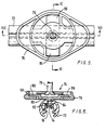
- Fig. 14 is a perspective view of a track power supply connector incorporating a thermal cut-out;
- Figs. 15, 16 and 17 respectively are an end view, a plan view and a side view of a side contact in the connector of Fig. 14;
- Figs. 18, 19 and 20 respectively are an end view, a plan view and a side view of a centre contact in the connector of Fig. 14, Fig, 20 being turned through a right angle to fit on the sheet; and
- Figs. 21, 22, 23 and 24 respectively are a side view, a plan view, an underneath plan view and a section on line XXIV-XXIV of Fig. 21, of a rotary locking cam in the connector of Fig. 14.
- Like references refer to like parts throughout. Referring to Figs. 1 to 3, the illustrated
track 10 is a two-conductor track of which one conductor is an outer conductor formed by anextruded aluminium casing 12 and the other conductor is an inner conductor formed by acopper strip 14 which is insulated byinsulation 16, thestrip 14 being held in place bylips 18 ofinsulation 16. Theconductors insulation 16 all extend continuously (with uniform cross-sections) along the whole length of the track, theconductors adaptor 20 applied to thetrack 10 anywhere along the length of the track. Theinsulation 16 is of extruded plastic, havingwings 17 which are held resiliently in place underlips 19 ofcasing 12. - The
adaptor 20 comprises a plasticinsulating body 22 which fits between twosides track 10, being somewhat narrower than an integral flatplastic top 25 which abuts thetrack sides resilient cantilever arms body 22 in mutually opposite directions and are integral with thebody 22. The tip of eacharm 26 is formed with an outwardly projectinglip 28 which is interlockingly engageable with a respective one of thelips 19 ofcasing 12. The normal (i.e. unstressed) positions ofarms 26 are inward, disengaginglips 28 fromlips 19. - For biasing
arms 26 outward to interlocklips 28 withlips 19, theadaptor 20 comprises two pivotedmembers 30 which can be selectively pivoted from the 'open' position of Fig. 2 (for disengagement) to the 'closed' position of Fig. 3 (in which they displace the two pairs ofarms 26 apart into interlocking engagement with the track 10), aboutpivots 32. The twomembers 30 haveflat tops 34 which lie flush with thetop 25 of thebody 22 in the closed position of Fig. 3. It will be appreciated that the space between each pair ofarms portion 36 of therespective member 30 which comes between them. - The
adaptor 20 also comprises arotatable contact assembly 40 which makes electrical contact with thetrack 10 in any rotational position. Thecontact assembly 40 comprises a sub-assembly 42 (Fig. 2) of an electrical centre contact 44 (to contact the strip 14) and a split sleeve outer electrical contact 46 (to contact thelips 19 of casing 12). An insulating plastic grommet (not shown) inside thesleeve contact 46 receives and positions thecentre contact 44. Thesub-assembly 42 also includes twometal connector terminals contacts centre contact 44 engagesconductors 14, it is located by abottom end wall 23 ofbody 22. - The
contact assembly 40 also comprises, besides thesub-assembly 42, two semi-cylindrical half innerinsulating sleeves outer sleeve 54, abracket 56, twoelectrical connector terminals 58a, b (respectively crimped to insulation-coveredwires 60a, b) and awasher 62. - As assembled, the
half sleeves sub-assembly 42; aflange 64 of an upstandingintegral boss 66 ofbody 22 is rotatably received in acircular groove 52c ofsleeves contact assembly 40 on thebody 22. Thebracket 56 fits over thehalf sleeves tongues 56a which engagegrooves 52d inhalf sleeves 52a, b to lockbracket 56 against relative rotation. Theouter sleeve 54 also fits overhalf sleeves 52a, b and hastongues 54a engaging grooves 52d to prevent relative rotation. Theterminals 58a, b fit onto thetags wires 60a, b extending through thecentre hole 54b in the top of thesleeve 54 and through thewasher 62. - The
bracket 56 is adapted to support a spot- lamp (not shown) or other illuminating device, to which thewires 60a, b are connected (not shown). Because the entire contact assembly 40 (that is,sub-assembly 42, half-sleeves 52a, b,outer sleeve 54,bracket 56,terminals 58a, b,wires 60a, b and washer 62) rotates as one unit, thewires 60a, b never get twisted, either around themselves or around thebracket 56. - Furthermore, because the
contacts copper strip 14 and with thelips 19 ofcasing 12 respectively in all rotational positions ofcontact assembly 40. - The
adaptor 20 can be fitted to thetrack 10 anywhere along its length with themembers 30 initially 'open' as shown in Figs. 1 and 2, and locked in position by closingmembers 30 to the position of Fig. 3 in whicharms 26 are displaced positively outwardly to interlocklips 28 withlips 19. - Fig. 4 illustrates a modified
track 70 having acasing 72 of generally rounded, cylindrical configuration, in contrast to the rather angular configuration ofcasing 12 oftrack 10. In other respects thetrack 70 is similar totrack 10. - For mounting the
track 10 or thetrack 70 to a support, referring to Figs. 5 to 8 (which happen to show the modifiedtrack 70, withcopper strip 14 andinsulation 16 shown only in Fig. 6) afixing device 74 is provided comprising amounting member 76 mounted rotatably to the (not shown) support (e.g. by a screw 78), and a connectingpiece 80 slidingly connected to the back of thecasing 72 by means of engaging anundercut tongue 82 of the connectingpiece 80 in anundercut groove 84 incasing 72. Laterally projectingwings 86 of connectingpiece 80 are received through arectangular opening 88 in the outside face ofmounting member 76, which can then be rotated to retain thewings 86 inrecesses 90 inmounting member 76. Since connectingpiece 80 is slidable along thecasing 72 oftrack 70, accurate positioning is less critical, making assembly easier. - The
track 10 has an undercut groove (not shown) at the back of it, the same asgroove 84 oftrack 70, and hence can be mounted in the same way. - The modified
track 92 of Fig. 9 differs from thetrack 70 of Fig. 4 in having two circular cross- sectionedcopper rods 94 partly embedded in and extending along thealuminium casing 96. Thecontact 46 of theadaptor 20 engages and makes electrical contact with exposedinner surfaces 98 of the twocopper rods 96. In other respects thetrack 92 is identical to thetrack 70. - In the modification of Figs. 10 and 11, as compared with the arrangements described hereinabove, like references refer to like parts. However, the above-mentioned plastic grommet (not shown) of adaptor is omitted from the adaptor 20' of Fig. 10. Furthermore, the half
inner sleeves 52a', 52b' are provided with a cross-partition 100 just below theterminals centre contact 44, carries acompression spring 102 which acts between thepartition 100 and a bend at 104 in connector tap 48', to bias thecontact 44 down onto the conductor strip 14' of track 70 (compare Fig. 4). - The
double track 100 of Fig. 12 comprises two co-extensive, back-to-back tracks tracks unitary casing member 106 which is generally H-shaped except that thesides - The
triple track 110 of Fig. 13 comprises three co-extensive, side-by-side tracks unitary casing member 118. - Whereas the
track 10 of Fig. 1 could be described as of generally triangular cross-section and the tracks of Figs. 4, 6, 9 and 11 as of generally cylindrical cross-section, the track of Fig. 13 is generally rectangular in cross-section and has arear mounting groove 120. - The two
tracks double track 100 of Fig. 12 can be separately switched, as can the threetracks triple track 110 of Fig. 13. - Referring to Figs. 14 to 24, a track
power supply connector 122 incorporates a thermally-activated current-sensitive cut-out device 124 (hereinafter referred to as a thermal cut-out device 124) with areset button 126 and is adapted to supply electrical power to the track 92 (see also Fig. 9) from a twin-conductor power lead 128. - More particularly, a side contact 130 (Figs. 14 to 17) of
connector 122 connectsconductor 132 ofpower lead 128 electrically tocopper rods 94 oftrack 92.Side contact 130 has ametal ferrule 134 integral with twometal spring contacts ferrule 134 is crimped in well-known manner toconductor 132, having aninner ear 140 to engageconductor 132 itself and anouter ear 142 to engage the insulation ofpower lead 128. The spring contacts 136,138, which are separated by aslot 144, fit springily betweenconductor rods 94 and engage the side surfaces 98 (Fig. 9) thereof. - The other conductor 146 of
power lead 128 is connected to the input of the thermal cut-outdevice 124 by aferrule 148. The thermal cut-outdevice 124 incorporates a mechanism, not illustrated, of well-known type, including a bimetallic strip which carries all the current to thetrack 92 and which is effective upon excessive current, that uyto say an overload, causing corresponding deflection of the strip, to open a pair of electrical contacts of the mechanism so as to cut off electrical power from thetrack 92. The mechanism is designed for this pair of electrical contacts to remain open until closed (after cooling of the bimetallic strip) upon operation ofreset button 126. - A centre contact 150 (Figs. 14 and 18 to 20) connects the output of the thermal cut-out
device 124 to thecopper strip 14. Thecentre contact 150 has threespring contacts copper strip 14. An insulating partition 158 (Fig. 14) separatesferrule 148 fromcentre contact 150. - To lock the
connector 122 onto thetrack 92, theconnector 122 is provided with a rotary locking cam 160 (Figs. 14 and 21 to 24) comprising acam head 162 connected integrally to across-slotted operating head 164 by ashaft 166. The two "ears" of thecam head 162 engage undersides 168 (Fig. 9) oftrack 92. - The
connector 122 comprises ahousing 170 of insulating material that houses the cut-outdevice 124,contacts ferrule 148 and rotatably supports thelocking cam 160.
Claims (14)
Priority Applications (1)
| Application Number | Priority Date | Filing Date | Title |
|---|---|---|---|
| AT87303229T ATE60170T1 (en) | 1986-04-11 | 1987-04-13 | LOW VOLTAGE POWER SUPPLY SYSTEM USING A TWO-WIRE BUSBAR. |
Applications Claiming Priority (2)
| Application Number | Priority Date | Filing Date | Title |
|---|---|---|---|
| GB868608900A GB8608900D0 (en) | 1986-04-11 | 1986-04-11 | Low voltage distribution system |
| GB8608900 | 1986-04-11 |
Publications (3)
| Publication Number | Publication Date |
|---|---|
| EP0241318A2 EP0241318A2 (en) | 1987-10-14 |
| EP0241318A3 EP0241318A3 (en) | 1989-01-04 |
| EP0241318B1 true EP0241318B1 (en) | 1991-01-16 |
Family
ID=10596060
Family Applications (1)
| Application Number | Title | Priority Date | Filing Date |
|---|---|---|---|
| EP87303229A Expired - Lifetime EP0241318B1 (en) | 1986-04-11 | 1987-04-13 | Low voltage distribution system with two-conductor track |
Country Status (10)
| Country | Link |
|---|---|
| US (1) | US4776809A (en) |
| EP (1) | EP0241318B1 (en) |
| AT (1) | ATE60170T1 (en) |
| AU (1) | AU597961B2 (en) |
| CA (1) | CA1297173C (en) |
| DE (2) | DE241318T1 (en) |
| ES (1) | ES2019382B3 (en) |
| GB (1) | GB8608900D0 (en) |
| GR (1) | GR3001786T3 (en) |
| NZ (1) | NZ219953A (en) |
Families Citing this family (60)
| Publication number | Priority date | Publication date | Assignee | Title |
|---|---|---|---|---|
| DE3817132A1 (en) * | 1987-05-20 | 1988-12-01 | Halloform Gmbh & Co Kg | Low-voltage busbar |
| DE3818078C2 (en) * | 1988-05-25 | 1998-04-30 | Wago Verwaltungs Gmbh | Electrical connector with phase selection |
| AU645667B2 (en) * | 1988-06-20 | 1994-01-20 | Concord Lighting Limited | Electric current distribution apparatus |
| GB2229585B (en) * | 1989-03-23 | 1993-07-07 | Rotaflex Ltd | Electric coupling |
| WO1989012918A1 (en) * | 1988-06-20 | 1989-12-28 | Gte Rotaflex Limited | Electric current distribution apparatus |
| GB2245698B (en) * | 1990-07-03 | 1994-08-31 | Powerlite Electrical Products | Lighting track system |
| IT221883Z2 (en) * | 1991-05-24 | 1994-12-06 | Tekno Lit Di Zucchini E Lazzar | CURRENT DISTRIBUTION EQUIPMENT FOR ELECTRIC LINES OF THE TYPE A PROFILE IN VIEW, ESPECIALLY FOR LOW VOLTAGE LIGHTING SYSTEMS |
| US5334037A (en) * | 1993-09-07 | 1994-08-02 | Juno Lighting, Inc. | Adapter box for low voltage fixture |
| US5429530A (en) * | 1994-05-20 | 1995-07-04 | The Toro Company | Cable connector including thermal fuse |
| FI101758B (en) * | 1996-02-16 | 1998-08-14 | Nordic Aluminium Oyj | Arrangement in connection with the contact rail |
| US5702177A (en) * | 1996-03-25 | 1997-12-30 | Lin; Ching-Yuan | Orbital lamp |
| US6527406B1 (en) * | 1996-04-12 | 2003-03-04 | Powerwall, Inc. | Integrally powered modular furniture |
| US5695261A (en) * | 1996-04-12 | 1997-12-09 | Slesinger; Bruce M. | Integrally powered modular furniture |
| FI101755B1 (en) * | 1996-11-28 | 1998-08-14 | Nordic Aluminium Oyj | Device at a power outlet for a contact rail system |
| FI101754B (en) * | 1996-11-28 | 1998-08-14 | Nordic Aluminium Oyj | Arrangement in connection with the busbar pantograph |
| US5942724A (en) * | 1997-09-23 | 1999-08-24 | The Wiremold Company | Wire containment system for mounting on a wall structure |
| US6079992A (en) * | 1997-10-21 | 2000-06-27 | Genlyte Thomas Group Llc | Track lighting fixture |
| US6025558A (en) * | 1998-01-09 | 2000-02-15 | Molex Incorporated | Electrical cable management system |
| DE19806337A1 (en) * | 1998-02-05 | 1999-08-12 | Abke Hermann Elektro Kg | Single-phase low voltage current rail for furniture |
| FI106587B (en) * | 1999-04-15 | 2001-02-28 | Nordic Aluminium Oyj | Arrangement with contact rail |
| IT1313136B1 (en) * | 1999-08-10 | 2002-06-17 | Iguzzini Illuminazione Srl | DEVICE FOR COUPLING AN ADAPTER FOR LIGHTING EQUIPMENT TO AN ELECTRIFIED TRACK |
| DE20108792U1 (en) | 2001-05-25 | 2002-10-10 | Moebelwerk A Trueggelmann Gmbh | Profile element with track |
| US7025317B2 (en) * | 2002-03-07 | 2006-04-11 | Masas Fernando R | Methods and apparatus for suspending fixtures |
| US7011534B2 (en) * | 2004-04-28 | 2006-03-14 | Wei Hong Shen | Track adapter and track light kit equipped with the same |
| US7140888B1 (en) * | 2005-07-18 | 2006-11-28 | Teng-Chiung Chan | Track lighting |
| DE102005054252B4 (en) * | 2005-11-11 | 2009-04-02 | Sew-Eurodrive Gmbh & Co. Kg | System comprising profile rail and box and at least one holder, and method of attaching a box to a rail |
| DE102007034600B3 (en) | 2007-07-25 | 2009-02-26 | Friedrich Lütze Gmbh & Co. Kg | Mounting system with a device for arranging and fixing electrical units, in particular in a control cabinet |
| US7686642B2 (en) * | 2008-03-03 | 2010-03-30 | Tempo Industries, Inc. | Wire harness interconnection and retention method and apparatus |
| US8678612B2 (en) * | 2009-04-14 | 2014-03-25 | Phoseon Technology, Inc. | Modular light source |
| ITPD20110114A1 (en) * | 2011-04-12 | 2012-10-13 | Elesi Luce S R L | LIGHTING DEVICE |
| US9039230B2 (en) | 2011-08-03 | 2015-05-26 | Lunastream, Inc. | Apparatus, system, and method for track lighting |
| DE102011053770B4 (en) * | 2011-09-20 | 2013-07-04 | Phoenix Contact Gmbh & Co. Kg | Housing for receiving an electrical component and housing assembly with such a housing |
| CN104075145B (en) * | 2013-03-29 | 2016-07-06 | 深圳市海洋王照明工程有限公司 | A kind of light fixture |
| DE202013102943U1 (en) | 2013-07-04 | 2014-07-07 | studio dinnebier Dinnebier Blieske GbR (vertretungsberechtigte Gesellschafter: Johannes Dinnebier, 13008 Berlin und Jan Blieske, 14195 Berlin) | Busbar adapter and arrangement with busbar adapter and busbar |
| CN103919615B (en) * | 2014-04-30 | 2017-01-25 | 迈柯唯医疗设备(苏州)有限公司 | Medical crane box and stand columns for medical crane box |
| US10926667B2 (en) | 2018-05-04 | 2021-02-23 | Lear Corporation | Track assembly |
| US11358497B2 (en) | 2018-05-04 | 2022-06-14 | Lear Corporation | Track system having a rolling member |
| CN110444973B (en) * | 2018-05-04 | 2021-02-05 | 李尔公司 | Track assembly |
| US11040638B2 (en) | 2018-05-04 | 2021-06-22 | Lear Corporation | Track assembly |
| US10882420B2 (en) | 2019-03-08 | 2021-01-05 | Lear Corporation | Track assembly |
| US10906431B2 (en) | 2018-05-04 | 2021-02-02 | Lear Corporation | Track assembly |
| US10889208B2 (en) | 2018-05-04 | 2021-01-12 | Lear Corporation | Track assembly |
| US11040639B2 (en) | 2018-05-04 | 2021-06-22 | Lear Corporation | Track assembly |
| CN109103618B (en) * | 2018-09-05 | 2020-04-24 | 佛山市锐诚云智能照明科技有限公司 | Conductive terminal and current-converging conductive device adopting same |
| US11225201B2 (en) | 2018-12-10 | 2022-01-18 | Lear Corporation | Track assembly |
| US11440482B2 (en) | 2018-12-10 | 2022-09-13 | Lear Corporation | Track assembly |
| US10855037B2 (en) | 2018-12-17 | 2020-12-01 | Lear Corporation | Support assembly with a support member and a track assembly |
| US11117538B2 (en) | 2018-12-17 | 2021-09-14 | Lear Corporation | Electrical assembly |
| US11613220B2 (en) | 2018-12-17 | 2023-03-28 | Lear Corporation | Electrical assembly |
| US10950977B2 (en) | 2018-12-18 | 2021-03-16 | Lear Corporation | Track assembly for a vehicle component |
| US11040653B2 (en) | 2019-02-25 | 2021-06-22 | Lear Corporation | Track assembly |
| US11299075B2 (en) | 2019-03-06 | 2022-04-12 | Lear Corporation | Electrical assembly |
| US11807142B2 (en) | 2019-03-06 | 2023-11-07 | Lear Corporation | Electrical track assembly |
| US11463083B2 (en) | 2019-10-04 | 2022-10-04 | Lear Corporation | Electrical system |
| US11323114B2 (en) | 2019-10-04 | 2022-05-03 | Lear Corporation | Electrical system |
| US11634101B2 (en) | 2019-10-04 | 2023-04-25 | Lear Corporation | Removable component system |
| US11835119B2 (en) | 2020-02-21 | 2023-12-05 | Lear Corporation | Track system with a support member |
| US11505141B2 (en) | 2020-10-23 | 2022-11-22 | Lear Corporation | Electrical system with track assembly and support assembly |
| CN114263867A (en) * | 2021-12-24 | 2022-04-01 | 东莞天盛电子制品有限公司 | Insulation spacer, push-type switching assembly, track power connector and switching method |
| CN114484333A (en) * | 2022-01-10 | 2022-05-13 | 赛尔富电子有限公司 | Track lamp |
Citations (1)
| Publication number | Priority date | Publication date | Assignee | Title |
|---|---|---|---|---|
| AU4617072A (en) * | 1972-08-31 | 1972-10-26 | Oy Nokia Ab | A connecting plug fora current supply rail arrangement particularly for lighting purposes and for small sized motors |
Family Cites Families (16)
| Publication number | Priority date | Publication date | Assignee | Title |
|---|---|---|---|---|
| US2124269A (en) * | 1937-06-05 | 1938-07-19 | Trumbull Electric Mfg Co | Bus bar conduit distribution system |
| US3129751A (en) * | 1958-05-21 | 1964-04-21 | Beer Hans | Track assembly |
| US3243754A (en) * | 1965-02-17 | 1966-03-29 | Bert L Miller | Supporting and feeding system for pendant fluorescent lighting fixtures and the like |
| US3391377A (en) * | 1965-09-10 | 1968-07-02 | Insul 8 Corp | Electrical distribution system |
| DE1927940A1 (en) * | 1969-05-31 | 1971-06-03 | Hoffmeister & Sohn | Current collector (adapter) that can be inserted into the opening of an approximately U-shaped busbar having several bare conductors, with a control shaft running in the longitudinal direction of the busbar to influence the contact and locking springs |
| DE2104274A1 (en) * | 1970-02-03 | 1971-08-12 | Nokia Oy Ab | Connector |
| FR2079564A5 (en) * | 1970-02-05 | 1971-11-12 | Waks Maurice | |
| FI46787C (en) * | 1971-09-06 | 1973-06-11 | Nokia Oy Ab | Power take-off for electrical power strip. |
| BE789952A (en) * | 1971-10-13 | 1973-04-11 | Philips Nv | POWER SOCKET |
| DE2210516A1 (en) * | 1972-03-04 | 1973-09-13 | Staff & Schwarz Gmbh | ADAPTER FOR TRACKS |
| CH558914A (en) * | 1972-09-12 | 1975-02-14 | Buergisser Robert | Current supply conductor with lighting fittings - has a channel with a number of separate conductors |
| DE2320983A1 (en) * | 1973-04-26 | 1974-11-21 | Staff Kg | FEED-IN OR TRACK REMOVAL DEVICE |
| NL7810941A (en) * | 1978-11-03 | 1980-05-07 | Philips Nv | COMBINATION OF CURRENT TAKER AND VOLTAGE RAIL, AND PART OF THIS COMBINATION. |
| FR2455202A1 (en) * | 1978-12-26 | 1980-11-21 | Philips Ind Commerciale | Fixture for plastics or metal section to support - uses rotatable bracket to rotate section, esp. for electrical conduit fitting to ceiling |
| IT8321669V0 (en) * | 1983-04-28 | 1983-04-28 | Profilux Srl | STRUCTURE OF BIPOLAR ADAPTER FOR MULTIPOLAR ELECTRIC LINES OF THE ARMORED TYPE, PART OF INSTALLATIONS FOR INTERIOR LIGHTING. |
| US4688869A (en) * | 1985-12-12 | 1987-08-25 | Kelly Steven M | Modular electrical wiring track arrangement |
-
1986
- 1986-04-11 GB GB868608900A patent/GB8608900D0/en active Pending
-
1987
- 1987-04-09 US US07/036,265 patent/US4776809A/en not_active Expired - Lifetime
- 1987-04-10 CA CA000534460A patent/CA1297173C/en not_active Expired - Fee Related
- 1987-04-10 AU AU71419/87A patent/AU597961B2/en not_active Ceased
- 1987-04-13 AT AT87303229T patent/ATE60170T1/en not_active IP Right Cessation
- 1987-04-13 NZ NZ219953A patent/NZ219953A/en unknown
- 1987-04-13 DE DE198787303229T patent/DE241318T1/en active Pending
- 1987-04-13 ES ES87303229T patent/ES2019382B3/en not_active Expired - Lifetime
- 1987-04-13 DE DE8787303229T patent/DE3767345D1/en not_active Expired - Fee Related
- 1987-04-13 EP EP87303229A patent/EP0241318B1/en not_active Expired - Lifetime
-
1991
- 1991-04-16 GR GR91400496T patent/GR3001786T3/en unknown
Patent Citations (1)
| Publication number | Priority date | Publication date | Assignee | Title |
|---|---|---|---|---|
| AU4617072A (en) * | 1972-08-31 | 1972-10-26 | Oy Nokia Ab | A connecting plug fora current supply rail arrangement particularly for lighting purposes and for small sized motors |
Also Published As
| Publication number | Publication date |
|---|---|
| US4776809A (en) | 1988-10-11 |
| DE3767345D1 (en) | 1991-02-21 |
| ES2019382B3 (en) | 1991-06-16 |
| EP0241318A3 (en) | 1989-01-04 |
| DE241318T1 (en) | 1989-10-05 |
| GR3001786T3 (en) | 1992-11-23 |
| CA1297173C (en) | 1992-03-10 |
| GB8608900D0 (en) | 1986-05-14 |
| ATE60170T1 (en) | 1991-02-15 |
| EP0241318A2 (en) | 1987-10-14 |
| NZ219953A (en) | 1989-04-26 |
| AU7141987A (en) | 1987-10-15 |
| AU597961B2 (en) | 1990-06-14 |
Similar Documents
| Publication | Publication Date | Title |
|---|---|---|
| EP0241318B1 (en) | Low voltage distribution system with two-conductor track | |
| US7481658B2 (en) | Apparatus for distributing electrical power and/or communication signals | |
| EP1665475B1 (en) | Electrical power distribution apparatus | |
| USRE36030E (en) | Electric distributing system | |
| US8033711B2 (en) | Field bendable line voltage track lighting system | |
| US5418328A (en) | Electric distributing system | |
| US5759051A (en) | Raceway with track mounted electrical receptacles randomly placed | |
| US4533190A (en) | Electrical power track system | |
| AU721095B2 (en) | An electrical track and adapter assembly | |
| US5013251A (en) | Adaptor and mechanism for grounding a track light system | |
| EP0761023A1 (en) | A piercing terminal system | |
| ZA200501728B (en) | Apparatus for distributing electrical power and/orcommunication signals | |
| US6241064B1 (en) | Fitting, conductor rail and coupling device | |
| GB2149230A (en) | Electrical track distribution system | |
| GB2266810A (en) | Multi socket outlet assembly | |
| CA2305133C (en) | Raceway with track mounted electrical receptacles randomly placed |
Legal Events
| Date | Code | Title | Description |
|---|---|---|---|
| PUAI | Public reference made under article 153(3) epc to a published international application that has entered the european phase |
Free format text: ORIGINAL CODE: 0009012 |
|
| AK | Designated contracting states |
Kind code of ref document: A2 Designated state(s): AT BE CH DE ES FR GB GR IT LI LU NL SE |
|
| PUAL | Search report despatched |
Free format text: ORIGINAL CODE: 0009013 |
|
| AK | Designated contracting states |
Kind code of ref document: A3 Designated state(s): AT BE CH DE ES FR GB GR IT LI LU NL SE |
|
| 17P | Request for examination filed |
Effective date: 19890704 |
|
| DET | De: translation of patent claims | ||
| 17Q | First examination report despatched |
Effective date: 19890921 |
|
| GRAA | (expected) grant |
Free format text: ORIGINAL CODE: 0009210 |
|
| AK | Designated contracting states |
Kind code of ref document: B1 Designated state(s): AT BE CH DE ES FR GB GR IT LI LU NL SE |
|
| PG25 | Lapsed in a contracting state [announced via postgrant information from national office to epo] |
Ref country code: AT Effective date: 19910116 |
|
| REF | Corresponds to: |
Ref document number: 60170 Country of ref document: AT Date of ref document: 19910215 Kind code of ref document: T |
|
| REF | Corresponds to: |
Ref document number: 3767345 Country of ref document: DE Date of ref document: 19910221 |
|
| ET | Fr: translation filed | ||
| ITF | It: translation for a ep patent filed |
Owner name: STUDIO CONS. BREVETTUALE S.R.L. |
|
| PG25 | Lapsed in a contracting state [announced via postgrant information from national office to epo] |
Ref country code: LU Free format text: LAPSE BECAUSE OF NON-PAYMENT OF DUE FEES Effective date: 19910430 |
|
| PLBE | No opposition filed within time limit |
Free format text: ORIGINAL CODE: 0009261 |
|
| STAA | Information on the status of an ep patent application or granted ep patent |
Free format text: STATUS: NO OPPOSITION FILED WITHIN TIME LIMIT |
|
| 26N | No opposition filed | ||
| REG | Reference to a national code |
Ref country code: GR Ref legal event code: FG4A Free format text: 3001786 |
|
| EAL | Se: european patent in force in sweden |
Ref document number: 87303229.6 |
|
| REG | Reference to a national code |
Ref country code: GB Ref legal event code: 732E |
|
| PGFP | Annual fee paid to national office [announced via postgrant information from national office to epo] |
Ref country code: GR Payment date: 20000526 Year of fee payment: 14 |
|
| PGFP | Annual fee paid to national office [announced via postgrant information from national office to epo] |
Ref country code: GB Payment date: 20010418 Year of fee payment: 15 |
|
| PGFP | Annual fee paid to national office [announced via postgrant information from national office to epo] |
Ref country code: DE Payment date: 20010423 Year of fee payment: 15 |
|
| PGFP | Annual fee paid to national office [announced via postgrant information from national office to epo] |
Ref country code: SE Payment date: 20010425 Year of fee payment: 15 |
|
| PG25 | Lapsed in a contracting state [announced via postgrant information from national office to epo] |
Ref country code: GR Free format text: LAPSE BECAUSE OF NON-PAYMENT OF DUE FEES Effective date: 20010430 |
|
| PGFP | Annual fee paid to national office [announced via postgrant information from national office to epo] |
Ref country code: NL Payment date: 20010430 Year of fee payment: 15 |
|
| PGFP | Annual fee paid to national office [announced via postgrant information from national office to epo] |
Ref country code: CH Payment date: 20010502 Year of fee payment: 15 |
|
| PGFP | Annual fee paid to national office [announced via postgrant information from national office to epo] |
Ref country code: FR Payment date: 20010510 Year of fee payment: 15 |
|
| PGFP | Annual fee paid to national office [announced via postgrant information from national office to epo] |
Ref country code: ES Payment date: 20010530 Year of fee payment: 15 |
|
| PGFP | Annual fee paid to national office [announced via postgrant information from national office to epo] |
Ref country code: BE Payment date: 20010625 Year of fee payment: 15 |
|
| REG | Reference to a national code |
Ref country code: GB Ref legal event code: 732E |
|
| REG | Reference to a national code |
Ref country code: GB Ref legal event code: IF02 |
|
| PG25 | Lapsed in a contracting state [announced via postgrant information from national office to epo] |
Ref country code: GB Free format text: LAPSE BECAUSE OF NON-PAYMENT OF DUE FEES Effective date: 20020413 |
|
| PG25 | Lapsed in a contracting state [announced via postgrant information from national office to epo] |
Ref country code: SE Free format text: LAPSE BECAUSE OF NON-PAYMENT OF DUE FEES Effective date: 20020414 Ref country code: ES Free format text: LAPSE BECAUSE OF NON-PAYMENT OF DUE FEES Effective date: 20020414 |
|
| PG25 | Lapsed in a contracting state [announced via postgrant information from national office to epo] |
Ref country code: LI Free format text: LAPSE BECAUSE OF NON-PAYMENT OF DUE FEES Effective date: 20020430 Ref country code: CH Free format text: LAPSE BECAUSE OF NON-PAYMENT OF DUE FEES Effective date: 20020430 Ref country code: BE Free format text: LAPSE BECAUSE OF NON-PAYMENT OF DUE FEES Effective date: 20020430 |
|
| PG25 | Lapsed in a contracting state [announced via postgrant information from national office to epo] |
Ref country code: NL Free format text: LAPSE BECAUSE OF NON-PAYMENT OF DUE FEES Effective date: 20021101 Ref country code: DE Free format text: LAPSE BECAUSE OF NON-PAYMENT OF DUE FEES Effective date: 20021101 |
|
| EUG | Se: european patent has lapsed |
Ref document number: 87303229.6 |
|
| GBPC | Gb: european patent ceased through non-payment of renewal fee |
Effective date: 20020413 |
|
| REG | Reference to a national code |
Ref country code: CH Ref legal event code: PL |
|
| PG25 | Lapsed in a contracting state [announced via postgrant information from national office to epo] |
Ref country code: FR Free format text: LAPSE BECAUSE OF NON-PAYMENT OF DUE FEES Effective date: 20021231 |
|
| NLV4 | Nl: lapsed or anulled due to non-payment of the annual fee |
Effective date: 20021101 |
|
| REG | Reference to a national code |
Ref country code: FR Ref legal event code: ST |
|
| REG | Reference to a national code |
Ref country code: ES Ref legal event code: FD2A Effective date: 20030514 |
|
| PG25 | Lapsed in a contracting state [announced via postgrant information from national office to epo] |
Ref country code: IT Free format text: LAPSE BECAUSE OF NON-PAYMENT OF DUE FEES;WARNING: LAPSES OF ITALIAN PATENTS WITH EFFECTIVE DATE BEFORE 2007 MAY HAVE OCCURRED AT ANY TIME BEFORE 2007. THE CORRECT EFFECTIVE DATE MAY BE DIFFERENT FROM THE ONE RECORDED. Effective date: 20050413 |