EP0241908B1 - Apparatus for generating superhigh pressure - Google Patents
Apparatus for generating superhigh pressure Download PDFInfo
- Publication number
- EP0241908B1 EP0241908B1 EP87105506A EP87105506A EP0241908B1 EP 0241908 B1 EP0241908 B1 EP 0241908B1 EP 87105506 A EP87105506 A EP 87105506A EP 87105506 A EP87105506 A EP 87105506A EP 0241908 B1 EP0241908 B1 EP 0241908B1
- Authority
- EP
- European Patent Office
- Prior art keywords
- casing
- fluid pressure
- pressure
- bodies
- generating means
- Prior art date
- Legal status (The legal status is an assumption and is not a legal conclusion. Google has not performed a legal analysis and makes no representation as to the accuracy of the status listed.)
- Expired
Links
- 239000012530 fluid Substances 0.000 claims description 54
- 238000003825 pressing Methods 0.000 claims description 18
- 238000005304 joining Methods 0.000 claims description 3
- 238000009434 installation Methods 0.000 description 5
- 229910003460 diamond Inorganic materials 0.000 description 2
- 239000010432 diamond Substances 0.000 description 2
- 239000012212 insulator Substances 0.000 description 2
- 238000004519 manufacturing process Methods 0.000 description 2
- 239000000463 material Substances 0.000 description 2
- 241001270131 Agaricus moelleri Species 0.000 description 1
- 238000006243 chemical reaction Methods 0.000 description 1
- 238000010276 construction Methods 0.000 description 1
- 230000008878 coupling Effects 0.000 description 1
- 238000010168 coupling process Methods 0.000 description 1
- 238000005859 coupling reaction Methods 0.000 description 1
- 238000005520 cutting process Methods 0.000 description 1
- 230000001902 propagating effect Effects 0.000 description 1
- 230000000452 restraining effect Effects 0.000 description 1
- 230000001360 synchronised effect Effects 0.000 description 1
Images


Classifications
-
- B—PERFORMING OPERATIONS; TRANSPORTING
- B01—PHYSICAL OR CHEMICAL PROCESSES OR APPARATUS IN GENERAL
- B01J—CHEMICAL OR PHYSICAL PROCESSES, e.g. CATALYSIS OR COLLOID CHEMISTRY; THEIR RELEVANT APPARATUS
- B01J3/00—Processes of utilising sub-atmospheric or super-atmospheric pressure to effect chemical or physical change of matter; Apparatus therefor
- B01J3/06—Processes using ultra-high pressure, e.g. for the formation of diamonds; Apparatus therefor, e.g. moulds or dies
- B01J3/065—Presses for the formation of diamonds or boronitrides
- B01J3/067—Presses using a plurality of pressing members working in different directions
-
- B—PERFORMING OPERATIONS; TRANSPORTING
- B30—PRESSES
- B30B—PRESSES IN GENERAL
- B30B1/00—Presses, using a press ram, characterised by the features of the drive therefor, pressure being transmitted directly, or through simple thrust or tension members only, to the press ram or platen
- B30B1/32—Presses, using a press ram, characterised by the features of the drive therefor, pressure being transmitted directly, or through simple thrust or tension members only, to the press ram or platen by plungers under fluid pressure
-
- B—PERFORMING OPERATIONS; TRANSPORTING
- B30—PRESSES
- B30B—PRESSES IN GENERAL
- B30B11/00—Presses specially adapted for forming shaped articles from material in particulate or plastic state, e.g. briquetting presses, tabletting presses
- B30B11/004—Presses specially adapted for forming shaped articles from material in particulate or plastic state, e.g. briquetting presses, tabletting presses involving the use of very high pressures
-
- B—PERFORMING OPERATIONS; TRANSPORTING
- B30—PRESSES
- B30B—PRESSES IN GENERAL
- B30B11/00—Presses specially adapted for forming shaped articles from material in particulate or plastic state, e.g. briquetting presses, tabletting presses
- B30B11/007—Presses specially adapted for forming shaped articles from material in particulate or plastic state, e.g. briquetting presses, tabletting presses using a plurality of pressing members working in different directions
Definitions
- the present invention relates to an apparatus for generating superhigh pressure, more particularly the means with which the pressure is generated.
- Superhigh pressure generating apparatuses for producing diamond, carbide material , and the like are generally known. Pressure generated by such an apparatus can range from tens of thousands to several tens of thousands kg/cm 2 .
- One type of superhigh pressure generating apparatus known as the 'belt-type', is equipped with a disk-like cylinder having a hole in the center. A pair of anvils, the ends of which are projected, are respectively directed toward the aforesaid hole from both sides to generate superhigh pressure.
- Another type known as the 'diamond type', has anvils which are arranged in six directions, i.e. upper and lower, front and back,and left and right. These anvils are synchronized toward the center of the cylinder to generate very high pressure.
- a third type known as the 'split-sphere type', has a spherical body which is divided into six or eight sections to form an internal space in its central portion. This internal space is pressed from all directions in order to obtain very high pressure.
- this very high pressure apparatus is principally composed of a split sphere b for defining an internal space a in the center thereof, a casing c for accommodating the split sphere b, and a piston d for pressing the split sphere b into the casing c.
- the split sphere b is an assembly of split moving bodies e in the form of flat-top round-bottom quadrangular pyramids which are obtained when a sphere is equally divided into more than four sections and the tips or the peaks are cut.
- the split sphere b arrangement has in its center the internal spacea defined by the oppositely arranged split moving bodies e in order to accomodate therein an article to be pressed.
- the split moving bodies e are forced to move inwardly in a diametral direction, uniformly pressing the article from all directions.
- the casing c having room inside for accomodating the split sphere, is a cubic body.
- This casing c consists of an upper and a lower section obtained by horizontally cutting the cubic body so that it can accomodate the split sphere b. Said two sections are recessed spherically so as to provide enough room for the split sphere b in the middle of the casing c.
- the split moving bodies e respectively, can move slightly toward the center of the sphere inside said room.
- pressure chambers g which face each other and are contiguous from the recesses f.
- the center lines of the pressure chambers g are directed toward the center of the split sphere b.
- the pressure chambers g are formed to correspond to the split moving bodies e, and the split moving bodies e are adapted so that they move inwardly when fluid pressure is applied.
- Two sections of the casing c have flanges h, respectively, which protrude from the lateral side. Couplings i having a -,-shaped cross section are fitted into the flanges h to firmly clamp the split casing c.
- Hollow cylindrical pistons d are arranged inside the pressure chambers g. Curved head portions at the ends of the pistons d have the same curvature as that of the sphere b and are in contact with the outer surfaces of the split moving bodies e.
- Hydraulic pumps & which are provided outside of the casing c,are connected to the pressure chambers g through an oil passage k. Fluid pressure, supplied from the hydraulic pumps e, acts on the pistons d. The pistons d urge and move the split moving bodies e so that very high pressure can be applied to the article inside the internal space a. It should be noted that the fluid is not limited to oil but other fluids, if they are noncompressive, may also be employed.
- a supply of fluid pressure to the pressure chambers g can be carried out separately and independently from outside the casing c by the hydraulic pumps.e or the like.
- the installation of a hydraulic pump poses the problem that it makes the construction, such as piping, complicated. Since the fluid pressure to be supplied to the pressure chambers g should be of the order of several 1000 kg/cm 2 , it is generally necessary to provide one hydraulic pump for each pressure chamber g individually. Consequently, the structure of the entire apparatus becomes very complicated and it is necessary to secure a considerable amount of space for the installation.
- the hydraulic pump generally has a performance of 1000 to 2000 kg/cm2.
- the fluid pressure to be introduced into the pressure chambers g is larger than that, i.e, of the order of several 1000 kg/cm 2 , and therefore, special hydraulic pumps are required. Should a general type of hydraulic pump be used, some kind of technical measures must be taken to secure a high fluid pressure. In such cases, the apparatuses according to the prior art are expensive to manufacture.
- anvil-type apparatus having eight pistons.
- Soft insulator sheets are inserted between the sides of the anvils.
- the whole spherical assemblage comprised of eight anvils is covered with a pair of thick hemispherical rubber shells and placed in an oil reservoir.
- the oil pressure in the reservoir is raised, the insulator sheets are compressed and stretched, causing a progression of the anvils towards the center.
- the apparatus comprising said eight anvils is totally placed in said oil reservoir so that a considerable amount of space is necessary for the installation of the entire apparatus.
- very high pressure forces must be brought into contact with the movable bodies since the area to which the force is supplied is the entire spherical surface of the rubber shell.
- the fluid pressure generating means provided integrally with the casing, are pressed by the pressing force applied from outside of the casing. High pressure fluid is created simultaneously and introduced into the pressure chambers to thereby move the plurality of moving bodies, thus applying very high pressure to the intended article.
- a superhigh pressure apparatus which is principally composed of a plurality of movable bodies 3 arranged opposite to each other so as to define an internal space 2 for receiving an article to be pressed and a casing 5 having a spherical compartment 20 for said plurality of movable bodies 3 and having pressure chambers 4 for said movable bodies 3 to receive fluid pressure F in order to let said bodies 3 move inwardly.
- said apparatus shown in Fig. I comprises six split movable bodies 3 assembled to form a split sphere I pressing an article inside the internal space 2 in the diametral direction.
- the casing 5 has the spherical compartment 20 for accomodating the split movable bodies 3 and the pressure chambers 4 which are provided for pushing the split movable bodies 3 inwardly.
- the pressure chambers 4 are defined and formed so as to face the surface 6 as if they were attached to the split moving bodies 3 inside the casing 5.
- pistons 7 are provided on which fluid pressure F is exerted to move the split movable bodies 3 inwardly.
- the casing 5 is divided into an upper and a lower section so that the split movable bodies 3, or the like, can be received in said compartment 20.
- the casing 5 may be composed by joining a pair of split casing bodies 22, 23 at their surfaces 5a.
- the casing 5 is integrally equipped with fluid pressure generating means 21 in which high fluid pressure, which is to be supplied to the pressure chambers 4, is generated by pressing forces applied from outside of the casing 5.
- the split casing bodies 22 and 23, respectively, have rams II which protrude from the outer surfaces opposite to the joining surfaces 5a.
- Sleeve-like cylinders 12 are pro vided with the rams II so as to encircle the rams peripherally. These cylinders 12 are slidable axially against the rams II.
- disk-like head covers 13 having a seal ring 14 are provided on the openings 12a of the cylinders 12.
- the head covers 13 close the openings 12a of the cylinders 12 to define spaces 10 between the rams II wherein fluid pressure is generated.
- Fluid such as oil, is also sealed inside the fluid pressure forming spaces 10.
- Oil passages 15 bored in the casing 5 are provided between said spaces 10 and the pressure chambers 4. The oil passages 15 serve for introducing fluid pressure F generated inside said spaces 10 into the pressure chambers 4.
- the heads Ila of the rams II are designed so that when fluid pressure F is generated by pressing force, the resulting force of fluid pressure F is allowed to act vertically on the plane of the joined surfaces 5a of the split casing bodies 22, 23 bringing them into tight contact.
- the top planes Ila of the rams II are respectively parallel to the joined surfaces 5a.
- high fluid pressure F may be generated when the head covers 13 of the fluid pressure generating means 21 are clamped by pressing means such as a press to apply pressing force to the fluid pressure forming spaces 10.
- the fluid is introduced into the pressure chambers 4 through the oil passages 15 to move the split movable bodies 3 inwardly under high pressure, thereby applying superhigh pressure to the article.
- the casing 5 is integrally formed in its outer surface 5b with cylinders 25 which are shaped by recessing from the outer surface Sb and in which fluid F is sealed.
- cylinders 25 which are shaped by recessing from the outer surface Sb and in which fluid F is sealed.
- rams 26 are provided which are axially slidable. When the pressing force is applied to the rams 26, the fluid F sealed in the cylinders 25 takes over increased pressure and may be introduced into the chambers 4.
- a fluid pressure generating means 21 is integrally provided with one of the pair of split casing bodies 23.
- the chambers 4, into which fluid pressure F is introduced from the fluid pressure generating means 21, are connected with each other by a passag4e 27 bored inside the casing 5.
- a header 4a is formed in the interior of the split casing body 22 which is the one without the fluid pressure generating means 21.
- the chamber 4 located in the casing body 22 is connected to the header 4a
- the other chamber 4 inside the counterpart 23 is connected to the pressure generating means 21.
- the header 4a serves to balance the fluid pressure F propagating from the latter chamber 4.
- the passage 27 penetrates the contact plane of the joined surfaces 5a of the split casing bodies 22, 23.
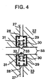
- a valving system is provided at this contact plane as shown in Fig. 4 and described below which cuts off the passage 27 in order to prevent leakage of oil when the split casing bodies 22, 23 are separated, and opens the passage 27 when they are joined.
- valve bodies 31 are provided being urged by springs 30 into sleeve-like holders 29. Each valve body 31 tightly closes an opening 32 of the holder 29 to cut off the passage 27.
- head portions 33 of the valve bodies 31 are moved away from each other against the spring 30, and the holes 32 of the holders 29 are opened and therewith the passage 27 also opens.
- the desired fluid pressure F may be secured by pressing by the pressing means, such as a press, which is installed outside of the casing 5.
- the apparatus can be one unit which contains a pressure generating means integrated with the casing 5, and thus it is not necessary to provide a piping installation outside of the casing 5 or to operate hydraulic pumps which are required for the apparatus according to the prior art. Hence, equipment and operation are simplified. Moreover, a press device or the like generally has a considerable pressing ability so that it is not necessary to use a hydraulic pump which is unsatisfactory in obtaining a higher pressure, or to use an expensive special hydraulic pump. Consequentially, it is possible to generate very high pressure as desired while also restraining an increase in cost.
- the apparatus may be built as a single unit, i.e., it is not necessary to install a separate hydraulic pump or to improve the ability of the hydraulic pump. Thus, equipment as well as operation may be simplified and costs are kept at a minimum.
Description
- The present invention relates to an apparatus for generating superhigh pressure, more particularly the means with which the pressure is generated.
- Superhigh pressure generating apparatuses for producing diamond, carbide material , and the like are generally known. Pressure generated by such an apparatus can range from tens of thousands to several tens of thousands kg/cm2. One type of superhigh pressure generating apparatus, known as the 'belt-type', is equipped with a disk-like cylinder having a hole in the center. A pair of anvils, the ends of which are projected, are respectively directed toward the aforesaid hole from both sides to generate superhigh pressure.
- Another type, known as the 'diamond type', has anvils which are arranged in six directions, i.e. upper and lower, front and back,and left and right. These anvils are synchronized toward the center of the cylinder to generate very high pressure.
- A third type, known as the 'split-sphere type', has a spherical body which is divided into six or eight sections to form an internal space in its central portion. This internal space is pressed from all directions in order to obtain very high pressure.
- The applicant has previously proposed a very high pressure apparatus which is modified over the 'split-sphere type' (Japanese Patent Application No. 225,128/1984).
- As shown in Fig. 5, this very high pressure apparatus is principally composed of a split sphere b for defining an internal space a in the center thereof, a casing c for accommodating the split sphere b, and a piston d for pressing the split sphere b into the casing c. The split sphere b is an assembly of split moving bodies e in the form of flat-top round-bottom quadrangular pyramids which are obtained when a sphere is equally divided into more than four sections and the tips or the peaks are cut. The split sphere b arrangement has in its center the internal spacea defined by the oppositely arranged split moving bodies e in order to accomodate therein an article to be pressed. The split moving bodies e are forced to move inwardly in a diametral direction, uniformly pressing the article from all directions. The casing c, having room inside for accomodating the split sphere, is a cubic body. This casing c consists of an upper and a lower section obtained by horizontally cutting the cubic body so that it can accomodate the split sphere b. Said two sections are recessed spherically so as to provide enough room for the split sphere b in the middle of the casing c. The split moving bodies e, respectively, can move slightly toward the center of the sphere inside said room. Also provided inside the casing c are pressure chambers g which face each other and are contiguous from the recesses f. The center lines of the pressure chambers g are directed toward the center of the split sphere b. The pressure chambers g are formed to correspond to the split moving bodies e, and the split moving bodies e are adapted so that they move inwardly when fluid pressure is applied. Two sections of the casing c have flanges h, respectively, which protrude from the lateral side. Couplings i having a -,-shaped cross section are fitted into the flanges h to firmly clamp the split casing c. Hollow cylindrical pistons d are arranged inside the pressure chambers g. Curved head portions at the ends of the pistons d have the same curvature as that of the sphere b and are in contact with the outer surfaces of the split moving bodies e.
- Hydraulic pumps & , which are provided outside of the casing c,are connected to the pressure chambers g through an oil passage k. Fluid pressure, supplied from the hydraulic pumps e, acts on the pistons d. The pistons d urge and move the split moving bodies e so that very high pressure can be applied to the article inside the internal space a. It should be noted that the fluid is not limited to oil but other fluids, if they are noncompressive, may also be employed.
- The above-described proposals and other conventional superhigh pressure apparatuses have the following drawbacks.
- A supply of fluid pressure to the pressure chambers g can be carried out separately and independently from outside the casing c by the hydraulic pumps.e or the like. However, the installation of a hydraulic pump poses the problem that it makes the construction, such as piping, complicated. Since the fluid pressure to be supplied to the pressure chambers g should be of the order of several 1000 kg/cm2, it is generally necessary to provide one hydraulic pump for each pressure chamber g individually. Consequently, the structure of the entire apparatus becomes very complicated and it is necessary to secure a considerable amount of space for the installation. On the other hand, the hydraulic pump generally has a performance of 1000 to 2000 kg/cm2. The fluid pressure to be introduced into the pressure chambers g is larger than that, i.e, of the order of several 1000 kg/cm2, and therefore, special hydraulic pumps are required. Should a general type of hydraulic pump be used, some kind of technical measures must be taken to secure a high fluid pressure. In such cases, the apparatuses according to the prior art are expensive to manufacture.
- In the document "The Review of Scientific Instruments", vol. 41, No. 8, August 1970, p. 1178 to 1179, there is disclosed an anvil-type apparatus having eight pistons. Soft insulator sheets are inserted between the sides of the anvils. The whole spherical assemblage comprised of eight anvils is covered with a pair of thick hemispherical rubber shells and placed in an oil reservoir. When the oil pressure in the reservoir is raised, the insulator sheets are compressed and stretched, causing a progression of the anvils towards the center. In this device the apparatus comprising said eight anvils is totally placed in said oil reservoir so that a considerable amount of space is necessary for the installation of the entire apparatus. Furthermore, to obtain a high pressure, very high pressure forces must be brought into contact with the movable bodies since the area to which the force is supplied is the entire spherical surface of the rubber shell.
- From document GB-A 1 023 449 an apparatus is known which comprises a pressure generating means which acts upon the reaction material by displacing the piston upwards with a ring. When the ring meets the plane surface of the blocks, the latter begin to be displaced upwardly in the stationary annulus along the common sliding surface. Therefore, the blocks are mechanically displaced upwardly by the contact of the ring with the plane surface. Even a second embodiment discloses said mechanical contact between the ring and the plane surface.
- It is an object of the invention to develop an apparatus identified in the precharacterizing clause of claim 1 which is easily constructed and, therefore, economical to manufacture.
- This object will be solved by an apparatus comprising the features of claim 1.
- The fluid pressure generating means, provided integrally with the casing, are pressed by the pressing force applied from outside of the casing. High pressure fluid is created simultaneously and introduced into the pressure chambers to thereby move the plurality of moving bodies, thus applying very high pressure to the intended article.
- The provision of such a fluid pressure generating means eliminates the need for the separate and independent installation of a hydraulic pump and overcomes the problem caused by insufficient pump performance when a standard hydraulic pump is used.
- Further embodiments of the invention are disclosed in the subclaims 2 to 9.
- The invention will be further described with reference to the drawings in which
- Fig. I is a side cross-sectional view showing a preferred embodiment of the present invention;
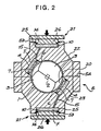
- Fig. 2 is a side cross-sectional view illustrating a second preferred embodiment of the present invention;
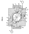
- Fig. 3 is a side cross-sectional view depicting a a third preferred embodiment of the present invention;
- Fig. 4 is an enlarged cross-sectional view of part A in Fig. 3; and
- Fig. 5 is a side cross-sectional view showing a device already proposed.
- In the drawings, only the split-sphere type superhigh pressure apparatus, which was introduced in the above-described proposed device, is depicted. However, it should be noted that the invention will be applied also to the superhigh pressure apparatus of the belt-type, diamond-type, or others.
- In Fig. I a superhigh pressure apparatus is shown which is principally composed of a plurality of
movable bodies 3 arranged opposite to each other so as to define an internal space 2 for receiving an article to be pressed and a casing 5 having aspherical compartment 20 for said plurality ofmovable bodies 3 and havingpressure chambers 4 for saidmovable bodies 3 to receive fluid pressure F in order to let saidbodies 3 move inwardly. - More specifically, said apparatus shown in Fig. I comprises six split
movable bodies 3 assembled to form a split sphere I pressing an article inside the internal space 2 in the diametral direction. The casing 5 has thespherical compartment 20 for accomodating the splitmovable bodies 3 and thepressure chambers 4 which are provided for pushing the splitmovable bodies 3 inwardly. - The
pressure chambers 4 are defined and formed so as to face thesurface 6 as if they were attached to thesplit moving bodies 3 inside the casing 5. In thepressure chambers 4pistons 7 are provided on which fluid pressure F is exerted to move the splitmovable bodies 3 inwardly. - The casing 5 is divided into an upper and a lower section so that the split
movable bodies 3, or the like, can be received in saidcompartment 20. The casing 5 may be composed by joining a pair ofsplit casing bodies surfaces 5a. The casing 5 is integrally equipped with fluid pressure generating means 21 in which high fluid pressure, which is to be supplied to thepressure chambers 4, is generated by pressing forces applied from outside of the casing 5. Thesplit casing bodies surfaces 5a. Sleeve-like cylinders 12 are pro vided with the rams II so as to encircle the rams peripherally. Thesecylinders 12 are slidable axially against the rams II. Above the rams II, disk-like head covers 13 having aseal ring 14 are provided on the openings 12a of thecylinders 12. The head covers 13 close the openings 12a of thecylinders 12 to definespaces 10 between the rams II wherein fluid pressure is generated. Fluid, such as oil, is also sealed inside the fluidpressure forming spaces 10.Oil passages 15 bored in the casing 5 are provided between saidspaces 10 and thepressure chambers 4. Theoil passages 15 serve for introducing fluid pressure F generated inside saidspaces 10 into thepressure chambers 4. - In the present embodiment, six split
movable bodies 3 and sixpressure chambers 4 are provided, and therefore, in each section of the casing 5 threeoil passages 15 connect saidspaces 10 to threepressure chambers 4. - The heads Ila of the rams II are designed so that when fluid pressure F is generated by pressing force, the resulting force of fluid pressure F is allowed to act vertically on the plane of the joined
surfaces 5a of thesplit casing bodies surfaces 5a. - With the above-described arrangement, high fluid pressure F may be generated when the head covers 13 of the fluid pressure generating means 21 are clamped by pressing means such as a press to apply pressing force to the fluid
pressure forming spaces 10. The fluid is introduced into thepressure chambers 4 through theoil passages 15 to move the splitmovable bodies 3 inwardly under high pressure, thereby applying superhigh pressure to the article. - In Fig. 2, the casing 5 is integrally formed in its outer surface 5b with
cylinders 25 which are shaped by recessing from the outer surface Sb and in which fluid F is sealed. Within thecylinders 25rams 26 are provided which are axially slidable. When the pressing force is applied to therams 26, the fluid F sealed in thecylinders 25 takes over increased pressure and may be introduced into thechambers 4. - In Fig. 3, a fluid pressure generating means 21 is integrally provided with one of the pair of
split casing bodies 23. Thechambers 4, into which fluid pressure F is introduced from the fluid pressure generating means 21, are connected with each other by apassag4e 27 bored inside the casing 5. In this case, aheader 4a is formed in the interior of thesplit casing body 22 which is the one without the fluid pressure generating means 21. Thechamber 4 located in thecasing body 22 is connected to theheader 4a Theother chamber 4 inside thecounterpart 23 is connected to the pressure generating means 21. Theheader 4a serves to balance the fluid pressure F propagating from thelatter chamber 4. In this embodiment thepassage 27 penetrates the contact plane of the joinedsurfaces 5a of thesplit casing bodies - A valving system is provided at this contact plane as shown in Fig. 4 and described below which cuts off the
passage 27 in order to prevent leakage of oil when thesplit casing bodies passage 27 when they are joined. In theopenings 28 of thepassages 27 which open in the direction of the joinedsurfaces 5a,valve bodies 31 are provided being urged bysprings 30 into sleeve-like holders 29. Eachvalve body 31 tightly closes anopening 32 of theholder 29 to cut off thepassage 27. In the case where the joinedsurfaces 5a are brought into contact with each other,head portions 33 of thevalve bodies 31 are moved away from each other against thespring 30, and theholes 32 of theholders 29 are opened and therewith thepassage 27 also opens. - In the present invention, since the fluid pressure generating means 21 is integrated with the casing 5, the desired fluid pressure F may be secured by pressing by the pressing means, such as a press, which is installed outside of the casing 5.
- As described above, the apparatus can be one unit which contains a pressure generating means integrated with the casing 5, and thus it is not necessary to provide a piping installation outside of the casing 5 or to operate hydraulic pumps which are required for the apparatus according to the prior art. Hence, equipment and operation are simplified. Moreover, a press device or the like generally has a considerable pressing ability so that it is not necessary to use a hydraulic pump which is unsatisfactory in obtaining a higher pressure, or to use an expensive special hydraulic pump. Consequentially, it is possible to generate very high pressure as desired while also restraining an increase in cost.
- The case where the same pressing force is applied to the split moving bodies should now be considered. If considerably high fluid pressure F can be secured by a press device or the like, it is possible to make the
piston 7 smaller than in the case where only lower pressure is obtained. Thus, thepiston 7 may be miniaturized as well as the entire system. Furthermore, since the head Ila of the ram II is designed so that the resulting force of the fluid pressure F acting thereon is applied vertically to the joinedsurfaces 5a, the contact between the joinedsurfaces 5a of the casing 5 may be secured by the fluid pressure F generated by actuation of the press device. - Since the fluid pressure generating means is integrally provided with the casing in order to introduce fluid pressure into the pressure chambers upon application of pressing force from the outside, the apparatus may be built as a single unit, i.e., it is not necessary to install a separate hydraulic pump or to improve the ability of the hydraulic pump. Thus, equipment as well as operation may be simplified and costs are kept at a minimum.
Claims (9)
Applications Claiming Priority (2)
| Application Number | Priority Date | Filing Date | Title |
|---|---|---|---|
| JP61084170A JPS62241544A (en) | 1986-04-14 | 1986-04-14 | Ultra-high-pressure generator |
| JP84170/86 | 1986-04-14 |
Publications (3)
| Publication Number | Publication Date |
|---|---|
| EP0241908A2 EP0241908A2 (en) | 1987-10-21 |
| EP0241908A3 EP0241908A3 (en) | 1988-08-24 |
| EP0241908B1 true EP0241908B1 (en) | 1990-12-19 |
Family
ID=13823019
Family Applications (1)
| Application Number | Title | Priority Date | Filing Date |
|---|---|---|---|
| EP87105506A Expired EP0241908B1 (en) | 1986-04-14 | 1987-04-14 | Apparatus for generating superhigh pressure |
Country Status (5)
| Country | Link |
|---|---|
| US (1) | US4905588A (en) |
| EP (1) | EP0241908B1 (en) |
| JP (1) | JPS62241544A (en) |
| CN (1) | CN1009811B (en) |
| DE (1) | DE3766741D1 (en) |
Families Citing this family (8)
| Publication number | Priority date | Publication date | Assignee | Title |
|---|---|---|---|---|
| US5440982A (en) * | 1993-07-01 | 1995-08-15 | Meadows; Stanley J. | Inking system for a printing press |
| US5526644A (en) * | 1995-06-07 | 1996-06-18 | Brieschke; Todd M. | Oil intensifier cylinder |
| MXPA05007723A (en) * | 2003-01-29 | 2005-09-30 | Sfk Systems As | A method and an apparatus for thawing frozen meat. |
| US6941633B2 (en) * | 2003-08-28 | 2005-09-13 | United Technologies Corporation | Tooling provision for split cases |
| ES2258920B2 (en) * | 2005-02-21 | 2007-03-16 | Instituto De Monocristales, S.L. | MULTIYUNQUE CUBIC MACHINE OF SEMIESPHERIC PISTONS, TO PRODUCE HIGH PRESSURES AND HIGH TEMPERATURES. |
| US20060292302A1 (en) * | 2005-06-24 | 2006-12-28 | Robert Chodelka | Apparatus and method for growing a synthetic diamond |
| CN101889711B (en) * | 2010-06-25 | 2014-09-17 | 于亮 | Ultra-high-pressure processing equipment of fluid |
| CN102941037B (en) * | 2012-11-19 | 2014-10-22 | 吉林大学 | Multilayer multi-surface sphere splitting type high-pressure device |
Family Cites Families (20)
| Publication number | Priority date | Publication date | Assignee | Title |
|---|---|---|---|---|
| US1840953A (en) * | 1928-02-23 | 1932-01-12 | Baker Ice Machine Co Inc | Pressure actuated governor |
| FR858416A (en) * | 1939-04-26 | 1940-11-25 | Hurry | |
| US2867002A (en) * | 1956-02-01 | 1959-01-06 | Gassareck Fa | Press attachment |
| DE1028427B (en) * | 1956-08-31 | 1958-04-17 | Eisenwerk Wanheim G M B H | Sensor part of a hydraulic fluid linkage serving as a tensioning device |
| US3103699A (en) * | 1959-01-08 | 1963-09-17 | Barogenics Inc | Super-high pressure apparatus |
| US3107395A (en) * | 1959-11-27 | 1963-10-22 | Gen Electric | High pressure high temperature apparatus |
| GB1023449A (en) * | 1961-12-27 | 1966-03-23 | Asea Ab | Improvements in high pressure apparatus |
| US3271502A (en) * | 1962-10-26 | 1966-09-06 | Gen Electric | High pressure method and apparatus |
| US3150413A (en) * | 1962-12-13 | 1964-09-29 | Barogenics Inc | High pressure presses and components thereof |
| US3278993A (en) * | 1964-03-31 | 1966-10-18 | Barogenics Inc | Apparatus subjected to large tonnage loads and/or high pressures |
| US3318093A (en) * | 1965-01-13 | 1967-05-09 | James E Webb | Hydraulic drive mechanism |
| FR1540362A (en) * | 1967-04-12 | 1968-09-27 | Apparatus for the production of very high pressures | |
| DE1759429C3 (en) * | 1968-04-30 | 1973-12-20 | Villeroy & Boch Keramische Werke Kg, 6642 Mettlach | Device for pressing several plate-shaped pellets at the same time |
| GB1299431A (en) * | 1968-11-29 | 1972-12-13 | Herga Electric | Improvements in fluid actuators |
| AT289513B (en) * | 1969-06-27 | 1971-04-26 | Ges Fertigungstechnik & Maschb | Forging machine |
| DE2210608A1 (en) * | 1971-03-15 | 1972-09-28 | G B Boucherie Nv | Device for the step-by-step conveyance of machine parts, workpieces, tools and the like |
| GB1604495A (en) * | 1978-05-30 | 1981-12-09 | Hawkhead Bray & Sons Ltd | Press action machines |
| SU1148802A1 (en) * | 1984-01-26 | 1985-04-07 | Специальное Конструкторско-Технологическое Бюро По Товарам Культурно-Бытового Назначения И Хозяйственного Обихода Из Пластмасс Научно-Производственного Объединения "Полимербыт" | Hydraulic press |
| JPS61103534A (en) * | 1984-10-27 | 1986-05-22 | Ishikawajima Harima Heavy Ind Co Ltd | Ultrahigh pressure generating device |
| DE3513129A1 (en) * | 1985-04-12 | 1986-10-23 | Peter Dipl.-Ing. 6000 Frankfurt Schröck | Radial press having a plurality of pressure medium drives arranged in a radial fashion |
-
1986
- 1986-04-14 JP JP61084170A patent/JPS62241544A/en active Granted
-
1987
- 1987-04-09 US US07/036,414 patent/US4905588A/en not_active Expired - Fee Related
- 1987-04-14 CN CN87102749.6A patent/CN1009811B/en not_active Expired
- 1987-04-14 EP EP87105506A patent/EP0241908B1/en not_active Expired
- 1987-04-14 DE DE8787105506T patent/DE3766741D1/en not_active Expired - Fee Related
Also Published As
| Publication number | Publication date |
|---|---|
| EP0241908A3 (en) | 1988-08-24 |
| EP0241908A2 (en) | 1987-10-21 |
| CN87102749A (en) | 1987-10-28 |
| JPH0331095B2 (en) | 1991-05-02 |
| JPS62241544A (en) | 1987-10-22 |
| CN1009811B (en) | 1990-10-03 |
| DE3766741D1 (en) | 1991-01-31 |
| US4905588A (en) | 1990-03-06 |
Similar Documents
| Publication | Publication Date | Title |
|---|---|---|
| EP0241908B1 (en) | Apparatus for generating superhigh pressure | |
| JP3278437B2 (en) | Fluid control valve structure | |
| US3271502A (en) | High pressure method and apparatus | |
| US3093862A (en) | Compact hydrostatic pressure apparatus | |
| JP4607110B2 (en) | Clamp and / or brake device | |
| US4106586A (en) | Hydraulic vibrator | |
| KR850002880A (en) | Pneumatic cylinder with cushion mechanism and cushioning method | |
| CA2002662A1 (en) | Clamp ring assembly for air spring | |
| EP0923727B1 (en) | Improved fluid control valve arrangement | |
| US6022206A (en) | Cubic multi anvil device | |
| US5431089A (en) | Force generating mechanism | |
| US4543877A (en) | Device for the production of pressure | |
| US5778760A (en) | End cap for intermediate use in cylinder assembly and method | |
| US4362304A (en) | Packing arrangement for a floating piston | |
| US3874679A (en) | Sealing device | |
| JPS63270904A (en) | Pneumatic cylinder | |
| US3179979A (en) | High pressure die | |
| US3091804A (en) | Hydrostatic press for an elongated object | |
| US5549281A (en) | Liquid spring for punch press | |
| KR880012331A (en) | Dry Rubber Press Forming Method and Forming Equipment | |
| EP0152726A1 (en) | Pressure vessel for high-pressure apparatus | |
| US3364533A (en) | Clamping device | |
| US4400967A (en) | Crimping collet | |
| US4508326A (en) | Pressure chuck for irregular articles | |
| US4443134A (en) | Yieldable roof support for mine passages and the like |
Legal Events
| Date | Code | Title | Description |
|---|---|---|---|
| PUAI | Public reference made under article 153(3) epc to a published international application that has entered the european phase |
Free format text: ORIGINAL CODE: 0009012 |
|
| AK | Designated contracting states |
Kind code of ref document: A2 Designated state(s): AT BE CH DE ES FR GB GR IT LI LU NL SE |
|
| RBV | Designated contracting states (corrected) |
Designated state(s): DE FR GB SE |
|
| PUAL | Search report despatched |
Free format text: ORIGINAL CODE: 0009013 |
|
| AK | Designated contracting states |
Kind code of ref document: A3 Designated state(s): DE FR GB SE |
|
| 17P | Request for examination filed |
Effective date: 19880902 |
|
| 17Q | First examination report despatched |
Effective date: 19890823 |
|
| GRAA | (expected) grant |
Free format text: ORIGINAL CODE: 0009210 |
|
| AK | Designated contracting states |
Kind code of ref document: B1 Designated state(s): DE FR GB SE |
|
| REF | Corresponds to: |
Ref document number: 3766741 Country of ref document: DE Date of ref document: 19910131 |
|
| ET | Fr: translation filed | ||
| PLBE | No opposition filed within time limit |
Free format text: ORIGINAL CODE: 0009261 |
|
| STAA | Information on the status of an ep patent application or granted ep patent |
Free format text: STATUS: NO OPPOSITION FILED WITHIN TIME LIMIT |
|
| 26N | No opposition filed | ||
| PGFP | Annual fee paid to national office [announced via postgrant information from national office to epo] |
Ref country code: SE Payment date: 19930305 Year of fee payment: 7 |
|
| PGFP | Annual fee paid to national office [announced via postgrant information from national office to epo] |
Ref country code: FR Payment date: 19930405 Year of fee payment: 7 |
|
| PGFP | Annual fee paid to national office [announced via postgrant information from national office to epo] |
Ref country code: DE Payment date: 19930419 Year of fee payment: 7 |
|
| PGFP | Annual fee paid to national office [announced via postgrant information from national office to epo] |
Ref country code: GB Payment date: 19940331 Year of fee payment: 8 |
|
| PG25 | Lapsed in a contracting state [announced via postgrant information from national office to epo] |
Ref country code: SE Effective date: 19940415 |
|
| PG25 | Lapsed in a contracting state [announced via postgrant information from national office to epo] |
Ref country code: FR Effective date: 19941229 |
|
| PG25 | Lapsed in a contracting state [announced via postgrant information from national office to epo] |
Ref country code: DE Effective date: 19950103 |
|
| EUG | Se: european patent has lapsed |
Ref document number: 87105506.7 Effective date: 19941110 |
|
| REG | Reference to a national code |
Ref country code: FR Ref legal event code: ST |
|
| PG25 | Lapsed in a contracting state [announced via postgrant information from national office to epo] |
Ref country code: GB Effective date: 19950414 |
|
| GBPC | Gb: european patent ceased through non-payment of renewal fee |
Effective date: 19950414 |