EP0243659A1 - Surface exposure device for exposing text on a recording carrier, and method for this exposing - Google Patents
Surface exposure device for exposing text on a recording carrier, and method for this exposing Download PDFInfo
- Publication number
- EP0243659A1 EP0243659A1 EP87104141A EP87104141A EP0243659A1 EP 0243659 A1 EP0243659 A1 EP 0243659A1 EP 87104141 A EP87104141 A EP 87104141A EP 87104141 A EP87104141 A EP 87104141A EP 0243659 A1 EP0243659 A1 EP 0243659A1
- Authority
- EP
- European Patent Office
- Prior art keywords
- text
- data
- recording medium
- converter
- lines
- Prior art date
- Legal status (The legal status is an assumption and is not a legal conclusion. Google has not performed a legal analysis and makes no representation as to the accuracy of the status listed.)
- Granted
Links
Images


Classifications
-
- B—PERFORMING OPERATIONS; TRANSPORTING
- B41—PRINTING; LINING MACHINES; TYPEWRITERS; STAMPS
- B41B—MACHINES OR ACCESSORIES FOR MAKING, SETTING, OR DISTRIBUTING TYPE; TYPE; PHOTOGRAPHIC OR PHOTOELECTRIC COMPOSING DEVICES
- B41B19/00—Photoelectronic composing machines
-
- G—PHYSICS
- G06—COMPUTING; CALCULATING OR COUNTING
- G06F—ELECTRIC DIGITAL DATA PROCESSING
- G06F40/00—Handling natural language data
- G06F40/10—Text processing
- G06F40/103—Formatting, i.e. changing of presentation of documents
- G06F40/109—Font handling; Temporal or kinetic typography
-
- G—PHYSICS
- G06—COMPUTING; CALCULATING OR COUNTING
- G06K—GRAPHICAL DATA READING; PRESENTATION OF DATA; RECORD CARRIERS; HANDLING RECORD CARRIERS
- G06K15/00—Arrangements for producing a permanent visual presentation of the output data, e.g. computer output printers
- G06K15/02—Arrangements for producing a permanent visual presentation of the output data, e.g. computer output printers using printers
- G06K15/12—Arrangements for producing a permanent visual presentation of the output data, e.g. computer output printers using printers by photographic printing, e.g. by laser printers
- G06K15/1204—Arrangements for producing a permanent visual presentation of the output data, e.g. computer output printers using printers by photographic printing, e.g. by laser printers involving the fast moving of an optical beam in the main scanning direction
Definitions
- the invention relates to an area exposer for the area-wide exposure of text on a record carrier according to the preamble of claim 1.
- Another aspect of the invention relates to a method for areal exposure according to the preamble of claim 8.
- Area imagesetters that are set up with a laser recorder are understood to mean both laser printers that produce a final printed product and laser typesetting devices or systems that produce a typesetting product, namely typographically set text, which can only be applied to the printing form, in particular a printing plate, using further techniques is to be transferred.
- Laser printers and laser setting devices also differ essentially in that the latter set the typographic characters with higher resolution than the laser printer prints. Otherwise, the essential structures of interest here can be similar in laser printers and laser setting devices.
- the imagesetters are generally characterized by the fact that they do not build up characters one after the other line by line, whereby the exposure of the individual characters takes place with a grid at right angles to the line direction and after the end of a line of the recording medium on which the exposure was made, the line spacing is advanced, but instead that the recording medium is moved continuously in a feed direction transverse to the line direction, this feed movement is synchronized with the deflecting movement of a scanner and that the scanner scans the recording medium along horizontal scan lines across the width of several characters, in particular all characters of a line of text.
- Known area imagesetters have a polygon mirror as the scanner, which rotates at high speed and deflects an intensity-modulated scanning beam transverse to the direction of advance of a recording medium, in particular a film.
- the record carrier is continuously transported between two successive scan lines by a predetermined height.
- the deflection movement projected onto the recording medium extends at least over the so-called setting width, which is scanned with the scanning beam and exposed image-wise over a width corresponding to the text line to be exposed.
- setting width which is scanned with the scanning beam and exposed image-wise over a width corresponding to the text line to be exposed.
- the deflection of the beam for scanning the record carrier takes place there, however, with a resettable mirror which is moved in one direction at an essentially constant angular velocity, after which the mirror is quickly returned to its starting position and the scanning process is repeated after the receipt of a next trigger pulse.
- the material of the record carrier is also poorly used if only a long column is exposed along a length section of the record carrier.
- the present invention has for its object to develop a platesetter of the type mentioned in such a way that with high exposure speed (setting speed) and good use of the recording medium by the exposed text subsequent assembly operations can be largely dispensed with.
- the main advantage is achieved that the effective exposure speed (number of exposed characters per unit of time for a given typesetting task or text of a given size) is increased and the photosensitive recording medium is better used without text lengths that are smaller than that
- the specified setting width of an imagesetter is to require later installation of text segments. If the length of the text exceeds the specified setting width, however, there is also the possibility of splitting the text into segments in order to then expose only relatively few segments by 90 ° with respect to a normal position of the text on the recording medium and thus essentially to maintain the advantages indicated above.
- Another advantage of the imagesetter according to the invention is that the structure of known imagesetters can largely be retained and only the structure or mode of operation of a few process modules of the imagesetter can be changed, in particular the converter for rotating the text to be exposed on the recording medium by 90 ° with respect to the Normal position of the text. This simplifies the development, facilitates the possibility of later expansion of existing area imagesetters with the converter for rotating the text to be exposed and relieves the personnel who operate the area imagesetter and carry out the further processing of the text created with it.
- a customary output data processing system in which an X register for storing X distance data and a Y register for storing Y distance data are provided.
- the rotary Y-distance data and rotary X-distance data fed into the X-register and the Y-register by the converter can then be processed essentially conventionally, as if in the X-register X-distance data of the position of the characters and Y distance data of the positions of the lines would have been fed into the Y register.
- the structure and the mode of operation of the converter for generating the rotation X distance data and the rotation Y distance data is specified in claim 3. While generating the rotation X distance data is particularly easy, Since this corresponds to the normal Y-distance data, use is made of an additional grid for generating the rotating Y-distance data, which is placed over the text column assumed in the rotated position or its text data and is therefore also referred to as a rotating grid.
- the rotary grid lines of the rotary grid run in the X direction in accordance with the direction of the scanning movement of the scanner, which is controlled in the usual way with data and signals which are formed from output data of the output data processing system.
- the top rotary grid line has a freely selectable distance from the uppermost rotated character or its left side margin (designated after the normal position of the character).
- the rotary grid lines of the rotary grid adjoining it in the Y direction, ie in the feed direction of the recording medium, have constant distances from one another.
- rotary X distance data are formed for the left-hand side edge of the rotated characters, which are in the normal position and which, in the normal position, have approximately the same distances to the left-hand side edge of the recording medium.
- the rotary grid is preferably placed in such a way that a relatively large number of rotary X distance data can be related to each rotary grid line without the rotary X distances becoming too large and requiring too large rotary X distance numbers for a given positional accuracy.
- a text decoder which only activates the converter in predetermined cases.
- the text decoder according to claim 4 is constructed so that it includes the text data the end-of-line commands and the width values (thicknesses) of the characters in the text decrypt whether a given length to width ratio is exceeded. If this ratio is exceeded, the text decoder emits a signal which activates the converter, so that in this case the text is rotated by 90 ° to the normal position on the recording medium.
- the text decoder contains additional logic which recognizes additional information which suppresses the text rotation, although a length / width ratio of the text which is suitable for rotation can be determined.
- This additional information is in particular a user command that can arbitrarily exclude a text rotation, or information about image data contained in the text, since in this case conventional processing with a relatively uncomplicated converter, as described above, and a conventional output data processing system is not possible.
- a text segmenter is connected upstream of the converter for processing text columns whose length exceeds the setting width.
- the text segmenter groups the text data into text segment data, which command a division of the text to be exposed into segments along cutting lines in the line direction (X direction) if the unsegmented text would exceed the setting width after rotation.
- the division by the text segmenter can take into account additional conditions with which the cutting lines along which the text column is segmented are laid is that no picture grids (structures), also called tint, or borders are cut.
- the procedural aspect of the invention consists in an improvement of the method specified in the preamble of claim 8 in that for exposing the recording medium with text which exceeds a predetermined length to width ratio and is narrower than the recording medium by a predetermined amount, the recording medium in Line direction of the text is advanced and is scanned in the direction of the height of the characters of the text.
- the set width of the imagesetter used to expose the recording medium corresponds to the width of the recording medium, i.e. is only slightly less than the width of the record carrier, which has only very narrow, unscanned edge areas.
- the method according to the invention allows a substantial increase in the exposure speed if text columns are set which exceed a predetermined length to width ratio and have a smaller width than the setting width.
- the new method is used particularly advantageously if the text length of the text columns exceeds the text width.
- the text length may occasionally be referred to as the text height because it is defined in the direction of the height of the characters.
- the effective exposure speed in the exposure of relatively long but narrow text columns is increased and the light-sensitive recording medium is used well.
- the method can be carried out without changing the mechanical and optical part of an imagesetter used for its exercise. The virtually exclusively necessary changes to the electronic components of this platesetter are also not very expensive, as was shown in connection with the platesetter.
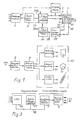
- FIG. 1, 1 designates a receiving module which obtains text data from a number of serial interfaces which are indicated by input arrows which are not identified.
- the text data define the identity, location, type (font number) and size of characters as well as setting commands, especially end-of-line commands.
- the text data can be output by input devices, not shown, in particular other computer systems or memories, such as floppy disks. Details of the text data and their input means can be found in DE-PS 29 40 897 (US Pat. No. 4,231,096).
- the input means can also include an input terminal with a keyboard and a display screen or a data transmission channel such as a telephone line.
- An input device 2 for character-specific data also belongs to the area exposer.
- Character-specific data are, in particular, data which define the contour or outline of each character of a character set, as well as width values (thicknesses) of the corresponding characters. Further details on the character-specific data can be found in DE-PS 29 40 897.
- Input devices for character-specific data belong to the prior art and are referred to in particular as "font handlers".
- the input device can obtain the font-specific data from font storage means, which are in particular designed as a floppy disk.
- the input device which is designed as a "font handler”
- can be connected to a floppy disk drive device which is not shown in FIG. 1.
- An essential component of a conventional imagesetter is an output data processing system, which is denoted by 4 in FIG. 1.
- the output data processing system is fed by the receiving module 1 with text data via a text memory 5, in which the text data of various serially fed setting tasks (jobs) are stored in an orderly manner.
- the text data arrive in the output data processing system 4 via an input 6.
- the output data processing system receives character-specific data from the input device 2 via an input 7.
- Conventional output data systems use the text data and the character-specific data to generate output data which are suitable for controlling a modulator of the scanning beam, the deflection movement of the scanner and the drive device.
- video signals can be obtained from the output data with which a laser beam is switched on and off or intensity-modulated as a scanning beam.
- third digital data are generated as output data from the text data and character-specific data, which are also referred to as first and second digital data.
- the output data processing system contains in particular a processor and data memory.
- the output data processing system can be embodied with a data management subsystem which provides data for a contour conversion subsystem in order to facilitate rapid processing of the data provided by the contour conversion subsystem.
- the contour conversion subsystem places stored ones in particular Outlines or contour data, ie character-specific data taking into account the text data into horizontal line data for the laser scanner.
- the horizontal line data is pixel data as essential output data.
- the output data memory is designated by 8 in FIG. 1.
- the output data processing system 4 contains, in addition to the X register, a Y register, in which data in the Y direction can be fed in according to the height of scanning lines or character spacing in the Y direction.
- a laser scanner 10 is connected to the output data memory 8, which records the output data, in particular pixel data, along scan lines, via a scan interface 9.
- the scanning interface 9 is controlled by control data from the output data system 4 and from the laser scanner 10 so that the pixel data are converted into video control signals for modulating the light modulator 11 in the laser scanner, with which pixels on the recording medium 12 are modulated.
- the scanning interface 9 outputs control signals for starting the drive device 13 of the recording medium.
- a scanning drive 14 for a scanning polygon 15 is also connected to the scanning interface so that the rotational speed of the polygon mirror is synchronized with the drive device of the recording medium.
- the polygon mirror 15 is driven by a motor 16 which is fed from a PLL controller 17.
- the drive of the polygon mirror is speed-controlled with the PLL controller.
- angle of rotation pulses from an angle of rotation pulse generator 19 are fed to the motor 16 via the pulse shaper 20 into an actual value input of the PLL controller.
- a setpoint input of this controller is fed with pulses from an adjustable frequency divider 21, which are derived from a frequency generator 22.
- the PLL controller regulates a constant speed of the motor 19 and the polygon mirror, which emits a scanning beam or
- Beams 23 are deflected over a scanning line 24.
- the recording medium 12 can be transported with a stepper motor 24 at a constant speed in the feed direction 25.
- a speed and position control device, generally designated 26 feeds a pulse of constant pulse frequency into the stepping motor 24, which is generated by the frequency generator or clock generator 22.
- the movement of the motor 16 which drives the polygon mirror is therefore synchronized with the feed caused by the stepping motor 24.
- a reference signal SOL from a pulse shaper 27 is also used, which is connected to a photosensitive element 27a which detects a specific position of the scanning beam 23 on the recording medium.
- the laser scanner also includes an optical system, which essentially consists of an aplanatic single lens 28, a field-flattening mirror 29, a deflecting line mirror 30 and an objective lens 31 and a diverging lens 23, which is a character projected into an intermediate image plane 33, i.e. Expose the pixels of the character on the recording medium 12.
- an optical system which essentially consists of an aplanatic single lens 28, a field-flattening mirror 29, a deflecting line mirror 30 and an objective lens 31 and a diverging lens 23, which is a character projected into an intermediate image plane 33, i.e. Expose the pixels of the character on the recording medium 12.
- FIG. 5 shows, by projecting the deflection movement of the polygon mirror onto the recording medium 12, the latter can be scanned over the width of the set and exposed imagewise over the width of a text.
- the scanning lines are designated Z1, Z2.
- the scanning lines run in a straight line and at a constant distance from each other approximately at right angles to the feed direction. (The slight inclination of the scanning lines is based on the finite scanning speed in relation to the feed speed of the recording medium.)
- the direction of advance of the record carrier is the Y direction, while the scanning movement is perpendicular to the X direction. It can be seen from FIG.
- the described imagesetter has the following components:
- a text decoder 34 is provided, which feeds the text data from the text memory either directly into the input 6 of the output data processing system 4 or into a converter 35.
- a text segmenter 36 can be interposed between the corresponding output of the text decoder and the input of the converter.
- the text data of the text to be exposed are fed into the text decoder 34 from the text memory 5, as are character-specific data, which are the widths (Dickten) of the characters to be exposed contain, from the input device 2 character-specific data. This data is used to determine whether the text to be exposed exceeds a predetermined length to width ratio and falls below the predetermined setting width by a predetermined amount. If these criteria are met, the converter 35 is activated by an output signal of the text decoder to rotate the text to be exposed by 90 ° with respect to a normal position of the text on the recording medium.
- the text decoder contains additional logic 34a, into which additional information can be fed in, which is intended to preclude a text rotation. For this purpose, an input 37 of the text decoder can be fed in in particular in the user command. Information about image data contained in the text, which likewise precludes rotation of the text to be set, can be obtained from the text data.
- the activated converter receives 38 text data and character-specific data at its input, from which transformed data are generated by the construction of the converter, which cause the text to be exposed to be rotated by 90 ° to its normal position during conventional processing of the converted data in the output data processing system.
- This transformed data is also referred to as rotation X distance data and rotation Y distance data.
- Corresponding X-distance data in the X-direction which are denoted by X0, X1 and X2, include distances between a left writing edge of the record carrier and the left side edge of the first character or plus the width values (thicknesses) of the subsequent characters that immediately follow connect the preceding character.
- the converter transforms the described Y distance data Y 1, Y 2 into rotary X distance data, which can also be related to the left writing edge, as shown in the right part for a text rotated by 90 ° to the normal position.
- the rotation X distance data are referred to as X r1 , X r2 .
- the distance between the rotation X distance data X r1 and X r2 corresponds to the line spacing between Y1 and Y2 in the text in the normal position.
- a rotary grid with rotary grid lines Y r0 , Y r1 , Y r2 etc. is superimposed on this to form the rotary Y distance data of the text rotated by 90 °.
- the rotary grid lines run in the X direction.
- the rotation Y distance date Y rR is now determined.
- the corresponding distances Y rT and Y r0 of the following characters are related to the rotary grid lines Y r1 .
- as many character spacings as possible are referenced to each rotary grid line, e.g. the spacing of the two characters T and 0 on Y r1 .
- the text data and character-specific data are output by the converter 35 in the form:
- the data described last, including the rotary Y data is fed via a line 39 from the converter into the Y register 40 in the output data processing system.
- the rotational X distance data flows via line 41 into the X register 42 in the output data processing system.
- the data stored in the X-register and the Y-register can then be used as a basis for the further functional and computing sequence.
- the left side edge or the left writing edge X r0 is equal to the normal left writing edge X0 and that the rotation X- Distance date X r1 can be freely selected.
- the position of the uppermost rotary grid line Y r1 can be freely selected, which is followed by the following rotary grid lines at constant intervals.
- the character data and the character-specific data of this text can be transformed directly. If, however, the length of the text to be rotated is the setting width exceeds, the text data and text-specific data are first divided into segments in a text segmenter upstream of the converter, in such a way that the segments rotated with the converter, which are to be exposed, take up the entire setting width as far as possible, but do not exceed it.
- the text segmenter thus contains comparison criteria for the width and length of the text to be set. For the rest, this text segmenter works in principle in a similar way to known text segmenters, in which, however, the text is split up to put the segments next to one another.
- the present text segmenter contains a logic 36a which precludes segmentation of the text along cutting lines which intersect image grids (structures) or borders, ie relocates the segmentation to areas of the text in which such image grids or borders do not occur. This deviates from the criterion mentioned at the beginning that the text segments take up the entire setting width.
- a section line along which the text which exceeds a predetermined length corresponding to the setting width is segmented is indicated by a broken line in FIG. 5 and designated by 43.
- FIG. 5 shows how a text column 44 is conventionally exposed on the recording medium 12 using the area exposer when the text is not to be rotated.
- the scanning movement runs in the direction of the lines or, in other words, in the direction of the width of the characters.
- the record carrier is transported transversely to it in the feed direction 25. It can be seen from FIG. 5 that a relatively large area remains in the right part of the record carrier, which area is not exposed with scanning lines Z1 and Z2.
- FIG. 6 shows how the text rotated by 90 ° with respect to the normal position fills the setting width of the record carrier. Above the rotated text column 45 shown, further rotated text columns or non-rotated text can then follow, which largely uses the area of the recording medium.
- FIG. 6 clearly shows the areal exposure method by which the record carrier is advanced in the line direction of the text, while at the same time the record carrier is scanned in the direction of the height of the text, so that the scanning lines Z1 and Z2 over the length of the text or of a text segment.
- the feed direction is in the direction of the width of the text or the characters that form the text.
- FIG. 3 shows a hardware implementation of part of the platesetter:
- a central processor unit 46 with serial channels, a main memory 47 designed as RAM and the output data memory 7 - compare also FIG. 1 - are in data-exchanging connection via a system bus 48.
- the central processor 46 and the main memory form a process computer which, according to its virtual structure, forms the process modules described for the reception module 1, the text memory 5, the text decoder 34, the converter 35, the text segmenter 36 and the output data processing system 4.
- the output data memory 7 and the scanning interface connected to it form the laser scanner interface logic, which enters into data exchange with the drive device and the scan drive and outputs video control data to the modulator, see FIG. 1.
- the drive device 13 in FIG. 1 corresponds to the motor 24 and the speed and position controller 26 in FIG. 4.
Abstract
Description
Die Erfindung betrifft einen Flächenbelichter zum flächenmäßigen Belichten von Text auf einem Aufzeichungsträger nach dem Oberbegriff des Anspruchs 1.The invention relates to an area exposer for the area-wide exposure of text on a record carrier according to the preamble of
Ein weiterer Aspekt der Erfindung betrifft ein Verfahren zum flächenmäßigen Belichten nach dem Oberbegriff des Anspruchs 8.Another aspect of the invention relates to a method for areal exposure according to the preamble of
Unter Flächenbelichtern, die mit einem Laserrecorder aufgebaut sind, werden sowohl Laserdrucker verstanden, die ein endgültiges Druckerzeugnis produzieren, als auch Lasersetzapparate oder -anlagen, die ein Satzprodukt, nämlich typographisch gesetzten Text erzeugen, der erst mit weiteren Techniken auf die Druckform, insbesondere eine Druckplatte zu übertragen ist. Laserdrucker und Lasersetzgeräte unterscheiden sich außerdem im wesentlichen dadurch, daß letztere die typographischen Schriftzeichen mit höherer Auflösung setzen als der Laserdrucker druckt. Im übrigen können jedoch die hier interessierenden wesentlichen Strukturen bei Laserdruckern und Lasersetzgeräten ähnlich sein.Area imagesetters that are set up with a laser recorder are understood to mean both laser printers that produce a final printed product and laser typesetting devices or systems that produce a typesetting product, namely typographically set text, which can only be applied to the printing form, in particular a printing plate, using further techniques is to be transferred. Laser printers and laser setting devices also differ essentially in that the latter set the typographic characters with higher resolution than the laser printer prints. Otherwise, the essential structures of interest here can be similar in laser printers and laser setting devices.
Die Flächenbelichter zeichnen sich generell dadurch aus, daß sie Schriftzeichen nicht einzeln nacheinander zeilenmäßig aufbauen, wobei die Belichtung der einzelnen Schriftzeichen mit einem Raster rechtwinklig zur Zeilenrichtung erfolgt und nach Abschluß einer Zeile der Aufzeichnungsträger, auf den belichtet wurde, um den Zeilenabstand weitergerückt wird, sondern daß der Aufzeichnungsträger kontinuierlich in einer Vorschubrichtung quer zur Zeilenrichtung bewegt wird, diese Vorschubbewegung mit der Ablenkbewegung eines Abtasters synchronisiert wird und daß dabei der Abtaster den Aufzeichnungsträger längs horizontalen Abtastlinien über die Breite mehrerer Schriftzeichen, insbesondere aller Schriftzeichen einer Textzeile abtastet.The imagesetters are generally characterized by the fact that they do not build up characters one after the other line by line, whereby the exposure of the individual characters takes place with a grid at right angles to the line direction and after the end of a line of the recording medium on which the exposure was made, the line spacing is advanced, but instead that the recording medium is moved continuously in a feed direction transverse to the line direction, this feed movement is synchronized with the deflecting movement of a scanner and that the scanner scans the recording medium along horizontal scan lines across the width of several characters, in particular all characters of a line of text.
Bekannte Flächenbelichter weisen als Abtaster einen Polygonspiegel auf, welcher mit hoher Drehzahl rotiert und einen intensitätsmodulierten Abtaststrahl quer zur Vorschubrichtung eines Aufzeichnungsträgers, insbesondere eines Films auslenkt. Zwischen zwei aufeinanderfolgenden Abtastlinien wird der Aufzeichnungsträger um eine vorgegebene Höhe kontinuierlich transportiert. Die auf den Aufzeichnungsträger projizierte Ablenkbewegung erstreckt sich dabei mindestens über die sogenannte Setzbreite, die mit dem Abtaststrahl abgetastet und über eine der zu belichtenden Textzeile entsprechende Breite bildmäßig belichtet wird. Infolge der hohen Geschwindigkeit der Abtastbewegung und der relativ großen Vorschubgeschwindigkeit werden damit hohe Setzgeschwindigkeiten erzielt ("Linotron 600"). Dies gilt jedenfalls dann, wenn die zu belichtende Zeilenbreite nicht wesentlich kleiner als die Setzbreite ist. Wenn jedoch im Verhältnis zur Setzbreite schmale Textspalten gesetzt werden sollen, erstreckt sich ein großer Teil der projizierten Ablenkbewegung nutzlos über den Aufzeichnungsträger, da während eines großen Teils der Abtastbewegung nicht bildmäßig belichtet wird. Da der mit der Abtastbewegung gekoppelte Vorschub des Aufzeichnungsträgers im wesentlichen konstant bleibt, wird zur Belichtung schmaler Zeilen die gleiche Zeit benötigt wie zur Belichtung breiter Zeilen. Dabei wird vorausgesetzt, daß mit einem Ausgabedatenverarbeitungssystem des Flächenbelichters Ausgabedaten zur Steuerung eines Modulators des Abtaststrahls aus empfangenen Textdaten und schriftzeichenspezifischen Daten so schnell erzeugt und gespeichert werden, daß der mit der Abtastbewegung synchronisierte Vorschub auch bei großen Zeilenbreiten des zu belichtenden Textes nicht gestoppt werden muß. Die Erzeugung solcher Ausgabedaten, welche die Modulation bzw. das Ein- und Ausschalten eines Abtaststrahls beim Abtasten längs der Abtastlinie beinhalten, gehört zum Stand der Technik (DE-PS 29 40 897), wonach Ausgabedaten, sogenannte dritte digitale Daten, welche Schnittstellen der Umrißlinien von mehreren Schriftzeichen mit jeweils einer Rasterlinie (Abtastlinie) angeben, in Rasterlinien-Speicherpuffer(n) gespeichert werden. Aus diesen sogenannten dritten digitalen Daten wird ein Videosteuersignal erzeugt, welches mittels eines Modulators den Abtaststrahl ein- und ausschaltet. Die Ablenkung des Strahls zum Abtasten des Aufzeichnungsträgers erfolgt dort allerdings mit einem rückstellbaren Spiegel, der mit im wesentlichen konstanter Winkelgeschwindigkeit in einer Richtung bewegt wird, wonach der Spiegel schnell in seine Ausgangslage zurückgestellt wird und der Abtastvorgang nach Eingang eines nächsten Triggerimpulses wiederholt wird.Known area imagesetters have a polygon mirror as the scanner, which rotates at high speed and deflects an intensity-modulated scanning beam transverse to the direction of advance of a recording medium, in particular a film. The record carrier is continuously transported between two successive scan lines by a predetermined height. The deflection movement projected onto the recording medium extends at least over the so-called setting width, which is scanned with the scanning beam and exposed image-wise over a width corresponding to the text line to be exposed. As a result of the high speed of the scanning movement and the relatively high feed rate, high setting speeds are achieved ("Linotron 600"). This applies in any case if the line width to be exposed is not significantly smaller than the set width. If, however, narrow text columns are to be set in relation to the setting width, a large part of the projected deflection movement extends uselessly over the recording medium, since a large part of the scanning movement does not expose imagewise. Since the advance of the recording medium coupled with the scanning movement remains essentially constant, the same time is required for the exposure of narrow lines as for the exposure of wide lines. It is assumed that with an output data processing system of the imagesetter, output data for controlling a modulator of the scanning beam from received text data and character-specific data are generated and stored so quickly that the feed synchronized with the scanning movement does not have to be stopped even with large line widths of the text to be exposed. The generation of such output data, which includes the modulation or the switching on and off of a scanning beam when scanning along the scanning line, is part of the prior art (DE-PS 29 40 897), according to which output data, so-called third digital data, which interfaces the contour lines Specify multiple characters, each with a raster line (scan line), are stored in raster line memory buffer (s). A video control signal is generated from these so-called third digital data, which switches the scanning beam on and off by means of a modulator. The deflection of the beam for scanning the record carrier takes place there, however, with a resettable mirror which is moved in one direction at an essentially constant angular velocity, after which the mirror is quickly returned to its starting position and the scanning process is repeated after the receipt of a next trigger pulse.
Abgesehen von der verhältnismäßig geringen Setzgeschwindigkeit bei dem Belichten von schmalen Textspalten bei konstanter Setzbreite mit kontinuierlichen gekoppelten Bewegungen des Abtasters und der Antriebseinrichtung des Aufzeichnungsträgervorschubs wird auch das Material des Aufzeichnungsträgers nur schlecht genutzt, wenn nur eine lange Spalte entlang eines Längenabschnitts des Aufzeichnungsträgers belichtet wird.In addition to the relatively low setting speed when exposing narrow text columns at a constant setting width with continuously coupled movements of the scanner and the drive device of the record carrier advance, the material of the record carrier is also poorly used if only a long column is exposed along a length section of the record carrier.
Es ist daher auch bekannt, einen Flächenbelichter der eingangs genannten Gattung ("Linotronic 600") mit einem Umsetzer auszurüsten, der Textdaten eines schmalen Textes, der ein vorgegebenes Länge- zu Breitenverhältnis überschreitet, in umgesetzte Textdaten eines eine größere Breite des Aufzeichnungsträgers einnehmenden Textes umsetzt. Der Text wird dazu längs Schnittlinien in Zeilenrichtung segmentiert, und die verhältnismäßig kurzen Textsegmente werden nebeneinander auf dem Aufzeichnungsträger belichtet. Dazu wird also längs einer Abtastlinie über die Breiten einer größeren Anzahl von Schriftzeichen abgetastet und belichtet. Nachteilig ist dabei jedoch, daß die Textsegmente anschließend wieder manuell zusammenmontiert werden müssen. Bei verhältnismäßig kurzen Textsegmenten steht die Montierarbeit zu dem erreichten Vorteil einer höheren Belichtungsgeschwindigkeit in keinem guten Verhältnis.It is therefore also known to equip an area imagesetter of the type mentioned at the beginning ("Linotronic 600") with a converter that contains text data of a narrow text that exceeds a predetermined length-to-width ratio. converts into converted text data of a text that occupies a larger width of the record carrier. For this purpose, the text is segmented along cut lines in the line direction, and the relatively short text segments are exposed next to one another on the recording medium. For this purpose, a large number of characters are scanned and exposed along a scanning line across the widths. However, it is disadvantageous that the text segments must then be assembled manually again. In the case of relatively short text segments, the montage work is not in a good relationship to the advantage achieved of a higher exposure speed.
Der vorliegenden Erfindung liegt die Aufgabe zugrunde, einen Flächenbelichter der eingangs genannten Gattung so weiterzubilden, daß bei hoher Belichtungsgeschwindigkeit (Setzgeschwindigkeit) und guter Ausnutzung des Aufzeichnungsträgers durch den belichteten Text auf anschließende Montagevorgänge weitgehend verzichtet werden kann.The present invention has for its object to develop a platesetter of the type mentioned in such a way that with high exposure speed (setting speed) and good use of the recording medium by the exposed text subsequent assembly operations can be largely dispensed with.
Diese Aufgabe wird durch die Ausbildung des Flächenbelichters mit den im kennzeichnenden Teil des Anspruchs 1 angegebenen Merkmalen gelöst.This object is achieved by the formation of the platesetter with the features specified in the characterizing part of
Mit dem erfindungsgemäßen Flächenbelichter wird der wesentliche Vorteil erzielt, daß die effektive Belichtungsgeschwindigkeit (Zahl der belichteten Zeichen pro Zeiteinheit für eine gegebene Satzaufgabe bzw. einen Text vorgegebnen Umfangs) erhöht wird und der lichtempfindliche Aufzeichnungsträger besser genutzt wird, ohne bei Textlängen, die kleiner als die vorgegebene Setzbreite eines Flächenbelichters sind, eine spätere Montage von Textsegmenten zu erfordern. Wenn die Länge des Textes die vorgegebene Setzbreite überschreitet, besteht jedoch auch die Möglichkeit, den Text in Segmenten aufzuspalten, um dann nur relativ wenige Segmente um 90° bezüglich einer Normalposition des Textes auf dem Aufzeichnungsträger zu belichten und damit im wesentlichen die voranstehend angegebenen Vorteile beizubehalten.With the platesetter according to the invention the main advantage is achieved that the effective exposure speed (number of exposed characters per unit of time for a given typesetting task or text of a given size) is increased and the photosensitive recording medium is better used without text lengths that are smaller than that The specified setting width of an imagesetter is to require later installation of text segments. If the length of the text exceeds the specified setting width, However, there is also the possibility of splitting the text into segments in order to then expose only relatively few segments by 90 ° with respect to a normal position of the text on the recording medium and thus essentially to maintain the advantages indicated above.
Ein weiterer Vorteil des erfindugnsgemäßen Flächenbelichters besteht darin, daß der Aufbau bekannter Flächenbelichter weitgehend beibehalten werden kann und nur die Struktur bzw. Arbeitsweise weniger Prozeßmodule des Flächenbelichters zu verändern ist, insbesondere des Umsetzers zur Drehung des auf den Aufzeichnungsträger zu belichtenden Textes um 90° bezüglich der Normalposition des Textes. Damit wird die Entwicklung vereinfacht, die Möglichkeit einer späteren Erweiterung vorhandener Flächenbelichter mit dem Umsetzer zur Drehung des zu belichtenden Textes erleichtert und das Personal, welches den Flächenbelichter betreibt und die Weiterverarbeitung des mit ihm erstellten Textes vornimmt, entlastet.Another advantage of the imagesetter according to the invention is that the structure of known imagesetters can largely be retained and only the structure or mode of operation of a few process modules of the imagesetter can be changed, in particular the converter for rotating the text to be exposed on the recording medium by 90 ° with respect to the Normal position of the text. This simplifies the development, facilitates the possibility of later expansion of existing area imagesetters with the converter for rotating the text to be exposed and relieves the personnel who operate the area imagesetter and carry out the further processing of the text created with it.
Insbesondere wird nach Anspruch 2 in Verbindung mit dem Umsetzer von einem üblichen Ausgabedatenverarbeitungssystem Gebrauch gemacht, in dem ein X-Register zur Speicherung von X-Abstandsdaten und ein Y-Register zur Speicherung von Y-Abstandsdaten vorgesehen ist. Die in das X-Register und in das Y-Register von dem Umsetzer eingespeisten Dreh-Y-Abstandsdaten und Dreh-X-Abstandsdaten können dann im wesentlichen konventionell verarbeitet werden, als ob in das X-Register X-Abstandsdaten der Position der Schriftzeichen und in das Y-Register Y-Abstandsdaten der Positionen der Zeilen eingespeist worden wären.In particular, according to
Die Struktur und die Wirkungsweise des Umsetzers zur Erzeugung der Dreh-X-Abstandsdaten und der Dreh-Y-Abstandsdaten ist in Anspruch 3 angegeben. Während die Erzeugung der Dreh-X-Abstandsdaten besonders einfach ist, da diese den normalen Y-Abstandsdaten entsprechen, wird zur Erzeugung der Dreh-Y-Abstandsdaten von einem Zusatzraster Gebrauch gemacht, welches über die in der gedrehten Lage angenommene Textspalte bzw. deren Textdaten gelegt wird und daher auch als Drehraster bezeichnet wird. Die Drehrasterlinien des Drehrasters verlaufen in X-Richtung entsprechend der Richtung der Abtastbewegung des Abtasters, der in üblicher Weise mit Daten und Signalen gesteuert wird, die von Ausgabedaten des Ausgabedatenverarbeitungssystems gebildet sind. Die oberste Drehrasterlinie hat zu dem obersten gedrehten Schriftzeichen bzw. dessen linken Seitenrand (bezeichnet nach der Normalposition des Schriftzeichens) einen frei wählbaren Abstand. Die sich daran in Y-Richtung, d.h. in Vorschubrichtung des Aufzeichnungsträgers anschließenden Drehrasterlinien des Drehrasters haben untereinander konstante Abstände. Bezogen auf die Drehrasterlinien werden Dreh-X-Abstandsdaten zu dem - in Normalposition gedachten linken - Seitenrand der gedrehten Schriftzeichen gebildet, die in Normalposition annähernd gleiche Abstände zu dem linken Seitenrand des Aufzeichnungsträgers haben. Das Drehraster wird vorzugsweise so gelegt, daß auf jede Drehrasterlinie relativ viele Dreh-X-Abstandsdaten bezogen werden können, ohne daß die Dreh-X-Abstände zu groß werden und bei gegebener Positionsgenauigkeit zu große Dreh-X-Abstandszahlen erfordern.The structure and the mode of operation of the converter for generating the rotation X distance data and the rotation Y distance data is specified in claim 3. While generating the rotation X distance data is particularly easy, Since this corresponds to the normal Y-distance data, use is made of an additional grid for generating the rotating Y-distance data, which is placed over the text column assumed in the rotated position or its text data and is therefore also referred to as a rotating grid. The rotary grid lines of the rotary grid run in the X direction in accordance with the direction of the scanning movement of the scanner, which is controlled in the usual way with data and signals which are formed from output data of the output data processing system. The top rotary grid line has a freely selectable distance from the uppermost rotated character or its left side margin (designated after the normal position of the character). The rotary grid lines of the rotary grid adjoining it in the Y direction, ie in the feed direction of the recording medium, have constant distances from one another. With respect to the rotary grid lines, rotary X distance data are formed for the left-hand side edge of the rotated characters, which are in the normal position and which, in the normal position, have approximately the same distances to the left-hand side edge of the recording medium. The rotary grid is preferably placed in such a way that a relatively large number of rotary X distance data can be related to each rotary grid line without the rotary X distances becoming too large and requiring too large rotary X distance numbers for a given positional accuracy.
Da der Flächenbelichter seine übliche Funktion beibehalten soll, in der die Schriftzeichen des Textes in Normalposition belichtet werden, d.h. Die Abtastbewegung und die Abtastlinien über die Breite der Schriftzeichen verlaufen, ist nach Anspruch 4 ein Textentschlüsseler vorgesehen, der den Umsetzer nur in vorbestimmten Fällen aktiviert. Insbesondere ist der Textentschlüsseler nach Anspruch 4 so aufgebaut, daß er die Textdaten einschließlich der Zeilenendkommandos sowie die Breitenwerte (Dickten) der Schriftzeichen des Textes entschlüsselt, ob ein vorgegebenes Länge- zu Breitenverhältnis überschritten wird. Bei überschreiten dieses Verhältnisses gibt der Textentschlüsseler ein den Umsetzer aktivierendes Signal ab, so daß in diesem Fall der Text um 90° gedreht zu der Normalposition auf dem Aufzeichnungsträger belichtet wird.Since the platesetter is to retain its usual function in which the characters of the text are exposed in the normal position, ie the scanning movement and the scanning lines run across the width of the characters, a text decoder is provided according to
Nach Anspruch 5 enthält der Textentschlüssler eine Zusatzlogik, welche Zusatzinformationen erkennt, die die Textdrehung unterdrücken, obwohl ein an sich geeignetes Länge- zu Breitenverhältnis des Textes zum Drehen festgestellt werden kann. Diese Zusatzinformationen sind insbesondere ein Anwenderbefehl, der willkürlich eine Textdrehung ausschließen kann, oder Informationen über in dem Text enthaltene Bilddaten, da in diesem Falle eine konventionelle Verarbeitung mit einem verhältnismäßig unkompliziert aufgebauten Umsetzer, wie voranstehend beschrieben, und einem üblichen Ausgabedatenverarbeitungssystem nicht möglich ist.According to
In Weiterbildung des Flächenblichters ist zur Verarbeitung von Textspalten, deren Länge die Setzbreite überschreitet, ein Textsegmentierer dem Umsetzer vorgeschaltet. Der Textsegmentierer gruppiert die Textdaten in Textsegmentdaten, die eine Aufteilung des zu belichtenden Textes in Segmenten längs Schnittlinien in Zeilenrichtung (X-Richtung) befehlen, wenn der unsegmentierte Text nach Drehung die Setzbreite überschreiten würde.In a further development of the area blaster, a text segmenter is connected upstream of the converter for processing text columns whose length exceeds the setting width. The text segmenter groups the text data into text segment data, which command a division of the text to be exposed into segments along cutting lines in the line direction (X direction) if the unsegmented text would exceed the setting width after rotation.
Nach Anspruch 7 kann die Aufteilung durch den Textsegmentierer unter Berücksichtigung von Zusatzbedingungen erfolgen, mit denen die Schnittlinien, längs derer die Textspalte segmentiert wird, so verlegt wird, daß keine Bildraster (Strukturen), auch Tint genannt, oder Umrandungen geschnitten werden.According to
Der verfahrensmäßige Aspekt der Erfindung besteht in einer Verbesserung des in dem Oberbegriff des Anspruchs 8 angegebenen Verfahrens darin, daß zum Belichten des Aufzeichnungsträgers mit Text, der ein vorgegebenes Länge- zu Breitenverhältnis überschreitet und um in vorbestimmtes Maß schmaler als der Aufzeichnungsträger ist, der Aufzeichnungsträger in Zeilenrichtung des Textes vorgeschoben wird und in Richtung der Höhe der Schriftzeichen des Textes abgetastet wird.The procedural aspect of the invention consists in an improvement of the method specified in the preamble of
Dabei wird davon ausgegangen, daß die Setzbreite des zur Belichtung des Aufzeichnungsträgers verwendeten Flächenbelichters der Breite des Aufzeichnungsträgers entspricht, d.h. nur wenig geringer als die Breite des Aufzeichnungsträgers ist, der nur sehr schmale nicht abgetastete Randbereiche aufweist.It is assumed here that the set width of the imagesetter used to expose the recording medium corresponds to the width of the recording medium, i.e. is only slightly less than the width of the record carrier, which has only very narrow, unscanned edge areas.
Danach erlaubt das erfindungsgemäße Verfahren eine wesentliche Erhöhung der Belichtungsgeschwindigkeit, wenn Textspalten gesetzt werden, die ein vorgegebenes Länge- zu Breitenverhältnis überschreiten, und eine kleinere Breite als die Setzbreite aufweisen.Thereafter, the method according to the invention allows a substantial increase in the exposure speed if text columns are set which exceed a predetermined length to width ratio and have a smaller width than the setting width.
Speziell wird das neue Verfahren vorteilhaft angewendet, wenn die Textlänge der Textspalten die Textbreite überschreitet.The new method is used particularly advantageously if the text length of the text columns exceeds the text width.
Es wird bemerkt, daß in der vorangehenden und nachfolgenden Beschreibung die Textlänge gelegentlich auch als Texthöhe bezeichnet werden kann, da sie in Richtung der Höhe der Schriftzeichen definiert ist.It is noted that in the foregoing and following description, the text length may occasionally be referred to as the text height because it is defined in the direction of the height of the characters.
Durch die Anwendung des erfindugnsgemäßen Verfahrens wird die effektive Belichtungsgeschwindigkeit bei dem Belichten verhältnismäßig langer, aber schmaler Textspalten erhöht und der lichtempfindliche Aufzeichnungsträger gut ausgenutzt. Das Verfahren kann ohne Änderung des mechanischen und optischen Teils eines zu seiner Ausübung verwendeten Flächenbelichters durchgeführt werden. Die praktisch ausschließlich notwendigen Änderungen der elektronischen Komponenten dieses Flächenbelichters sind ebenfalls wenig aufwendig, wie im Zusammenhang mit dem Flächenbelichter dargestellt wurde.By using the method according to the invention, the effective exposure speed in the exposure of relatively long but narrow text columns is increased and the light-sensitive recording medium is used well. The method can be carried out without changing the mechanical and optical part of an imagesetter used for its exercise. The virtually exclusively necessary changes to the electronic components of this platesetter are also not very expensive, as was shown in connection with the platesetter.
Die Erfindung wird im folgenden anhand einer Zeichnung mit sechs Figuren näher erläutert. Es zeigen:
Figur 1 wesentliche Prozeßmodule des Flächenbelichters in einer vereinfachten Blockdarstellung,Figur 2 eine Darstellung der Textdrehung zur Erläuterung des Umsetzers des Flächenbelichters,- Figur 3 eine grob schematische Realisierung des elektronischen Teils des Flächenbelichters nach
Figur 1 in einem Blockschaltbild, Figur 4 eine Darstellung des Abtasters des Flächenbelichters,Figur 5 einen mit dem Flächenbelichter konventionell belichteten Abschnitt eines Aufzeichnungsträgers und- Figur 6 einen Abschnitt des Aufzeichnungsträgers, der nach dem neuen Verfahren mit um 90° bezüglich der Normalposition gedrehten Text einer Textspalte belichtet ist.
- FIG. 1 essential process modules of the platesetter in a simplified block diagram,
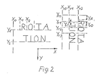
- FIG. 2 shows a representation of the text rotation to explain the converter of the platesetter,
- FIG. 3 shows a roughly schematic implementation of the electronic part of the platesetter according to FIG. 1 in a block diagram,
- FIG. 4 shows an illustration of the scanner of the platesetter,
- FIG. 5 shows a section of a recording medium which is conventionally exposed with the area exposer and
- FIG. 6 shows a section of the record carrier which, according to the new method, is exposed with text of a text column rotated through 90 ° with respect to the normal position.
Gemäß Fig. 1 ist mit 1 ein Empfangsmodul bezeichnet, welches Textdaten von mehreren seriellen Schnittstellen bezieht, welche mit nicht bezeichneten Eingangspfeilen angedeutet sind. Die Textdaten definieren die Identität, Lage, Art (Fontnummer) und Größe von Schriftzeichen sowie Setzbefehle, insbesondere Zeilenendkommandos. Die Textdaten können von nicht dargestellten Eingabeeinrichtungen, insbesondere anderen Rechnersystemen oder Speichern, wie Floppy Disks abgegeben werden. Einzelheiten zu den Textdaten und deren Eingabemitteln gehen aus der DE-PS 29 40 897 (US-PS 4 231 096) hervor. Zu den Eingabemitteln können auch ein Eingabeterminal mit einer Tastatur und einem Anzeigebildschirm (Display) oder ein Datenübertragungskanal wie eine Telefonleitung gehören. Weiter gehört zu dem Flächenbelichter eine Eingabeeinrichtung 2 schriftzeichenspezifischer Daten. Als schriftzeichenspezifische Daten gelten insbesondere Daten, welche die Kontur- oder Umrißlinien eines jeden Schriftzeichens eines Schriftzeichensatzes definieren, sowie Breitenwerte (Dickten) der entsprechenden Schriftzeichen. Weitere Einzelheiten zu den schriftzeichenspezifischen Daten gehen aus der DE-PS 29 40 897 hervor. Eingabeeinrichtungen schriftzeichenspezifischer Daten gehören zum Stand der Technik und werden insbesondere als "Font-Handler" bezeichnet. Die Eingabevorrichtung kann die schriftzeichenspezifischen Daten von Schriftzeichensatz-Speichermitteln beziehen, die insbesondere als Floppy Disk ausgebildet sind. Hierzu kann die Eingabeeinrichtung, die als "Font-Handler" ausgebildet ist, mit einer Floppy Disk-Antriebseinrichtung in Verbindung stehen, die in der Figur 1 nicht dargestellt ist. Es ist aber auch möglich, daß die Eingabeeinrichtung die schriftzeichenspezifischen Daten von dem Empfangsmodul 1 bezieht, was mit einer unterbrochen dargestellten Leitung 3 in Fig. 1 angedeutet ist.According to FIG. 1, 1 designates a receiving module which obtains text data from a number of serial interfaces which are indicated by input arrows which are not identified. The text data define the identity, location, type (font number) and size of characters as well as setting commands, especially end-of-line commands. The text data can be output by input devices, not shown, in particular other computer systems or memories, such as floppy disks. Details of the text data and their input means can be found in DE-PS 29 40 897 (US Pat. No. 4,231,096). The input means can also include an input terminal with a keyboard and a display screen or a data transmission channel such as a telephone line. An
Wesentlicher Bestandteil eines üblichen Flächenbelichters ist ein Ausgabedatenverarbeitungssystem, welches in Fig. 1 mit 4 bezeichnet ist. Das Ausgabedatenverarbeitungssystem wird von dem Empfangsmodul 1 mit Textdaten über einen Textspeicher 5 gespeist, in dem die Textdaten verschiedener seriell eingespeister Setzaufgaben (Jobs) geordnet gespeichert sind. Die Textdaten gelangen über einen Eingang 6 in das Ausgabedatenverarbeitungssystem 4. - Weiterhin erhält das Ausgabedatenverarbeitungssystem schriftzeichenspezifische Daten von der Eingabeeinrichtung 2 über eine Eingang 7.An essential component of a conventional imagesetter is an output data processing system, which is denoted by 4 in FIG. 1. The output data processing system is fed by the receiving
Übliche Ausgabedatensysteme erzeugen aus den Textdaten und den schriftzeichenspezifischen Daten Ausgabedaten, welche zur Steuerung eines Modulators des Abtaststrahls, der Ablenkbewegung des Abtasters sowie der Antriebseinrichtung geeignet sind. Insbesondere können aus den Ausgabedaten Videosignale gewonnen werden, mit denen ein Laserstrahl als Abtaststrahl ein- und ausgeschaltet bzw. intensitätsmoduliert wird.Conventional output data systems use the text data and the character-specific data to generate output data which are suitable for controlling a modulator of the scanning beam, the deflection movement of the scanner and the drive device. In particular, video signals can be obtained from the output data with which a laser beam is switched on and off or intensity-modulated as a scanning beam.
Die Struktur eines Ausgabedatenverarbeitungssystems und dessen Wirkungsweise sind im einzelnen in der DE-PS 29 40 897 beschrieben. Hiernach werden aus den Textdaten und schriftzeichenspezifischen Daten, die auch als erste und zweite digitale Daten bezeichnet werden, sogenannte dritte digitale Daten als Ausgabedaten erzeugt. Das Ausgabedatenverarbeitungssystem enthält insbesondere einen Prozessor und Datenspeicher. Das Ausgabedatenverarbeitungssystem kann mit einem Datenverwaltungsuntersystem ausgebildet werden, welches Daten für ein Konturenumsetzuntersystem bereitstellt, um eine rasche Verarbeitung der bereitgestellten Daten durch das Konturenumsetzuntersystem zu erleichtern. Das Konturenumsetzuntersystem setzt insbesondere gespeicherte Umrißlinien oder Konturendaten, d.h. schriftzeichenspezifische Daten unter Berücksichtigung der Textdaten in horizontale Strichdaten für den Laserabtaster um. Die horizontalen Strichdaten sind Bildpunktdaten als wesentliche Ausgabedaten.The structure of an output data processing system and its mode of operation are described in detail in DE-PS 29 40 897. According to this, so-called third digital data are generated as output data from the text data and character-specific data, which are also referred to as first and second digital data. The output data processing system contains in particular a processor and data memory. The output data processing system can be embodied with a data management subsystem which provides data for a contour conversion subsystem in order to facilitate rapid processing of the data provided by the contour conversion subsystem. The contour conversion subsystem places stored ones in particular Outlines or contour data, ie character-specific data taking into account the text data into horizontal line data for the laser scanner. The horizontal line data is pixel data as essential output data.
Das Konturenumsetzeruntersystem kann zur Bildung der horizontalen Strichdaten insbesondere folgende Prozeßschritte durchführen:
- (a) Ablesen von Daten, welche eine Textzeile und deren Größe identifizieren.
- (b) Ablesen des Abstands vom Schreibrand des Aufzeichnungsträgers zum linken Seitenrand des ersten Schriftzeichens und Speicherung in einem X-Register.
- (c) Ablesen schriftzeichenspezifischer Daten für das nächste Schriftzeichen und Umrechnung des Abstands von dem linken Schriftzeichenrand zur Kontur.
- (d) Ausgabe der Summe aus dem vorangehend gebildeten Wert und einem laufenden X-Wert an einen Rasterlinienpuffer.
- (e) Ablesen der nächsten Kontur und Wiederholen des Schrittes zur Umrechnung des Abstands vom linken Schriftzeichenrand zur Kontur, bis alle Konturen auf einer Höhe der Zeile errechnet sind.
- (f) Ablesen des Abstands zum linken Schriftzeichenrand des nächsten Schriftzeichens und Zuführen zu dem X-Register.
- (g) Schritte (c) - (f) wiederholen, bis alle Schriftzeichen in einer Zeile auf einer Höhe errechnet sind.
- (h) Übërtragung der Ausgabedaten (Bildpunktdaten) in einen Ausgabedatenspeicher.
- (a) Reading data identifying a line of text and its size.
- (b) Reading the distance from the writing edge of the recording medium to the left side edge of the first character and storage in an X register.
- (c) Reading character-specific data for the next character and converting the distance from the left character edge to the contour.
- (d) Output of the sum of the previously formed value and a running X value to a raster line buffer.
- (e) Reading the next contour and repeating the step to convert the distance from the left character edge to the contour until all contours have been calculated at the height of the line.
- (f) Reading the distance to the left character edge of the next character and feeding it to the X register.
- (g) Repeat steps (c) - (f) until all characters in one line have been calculated at one height.
- (h) Transfer of the output data (pixel data) into an output data memory.
Der Ausgabedatenspeicher ist in Fig. 1 mit 8 bezeichnet.The output data memory is designated by 8 in FIG. 1.
Das Ausgabedatenverarbeitungssystem 4 enthält außer dem X-Register ein Y-Register, in welches Daten in Y-Richtung entsprechend der Höhe von Abtastlinien bzw. von Schriftzeichenabständen in Y-Richtung eingespeist werden können.The output
Mit dem Ausgabedatenspeicher 8, welcher die Ausgabedaten, insbesondere Bildpunktdaten, entlang Abtastlinien aufnimmt, steht über eine Abtastschnittstelle 9 ein Laserabtaster 10 in Verbindung. Die Abtastschnittstelle 9 wird durch Steuerdaten von dem Ausgabedatensystem 4 und von dem Laserabtaster 10 so gesteuert, daß die Bildpunktdaten in Videosteuersignale zur Modulation des Lichtmodulators 11 in dem Laserabtaster umgewandelt werden, mit dem Bildpunkte auf dem Aufzeichnungsträger 12 moduliert werden. Außerdem gibt die Abtastschnittstelle 9 Steuersignale zum in Gang setzen der Antriebseinrichtung 13 des Aufzeichnungsträgers ab. Ein Abtastantrieb 14 für ein Abtastpolygon 15 steht ebenfalls mit der Abtastschnittstelle in Verbindung, damit die Drehgeschwindigkeit des Polygonspiegels mit der Antriebseinrichtung des Aufzeichnungsträgers synchronisiert wird.A
In Fig. 4 ist der als Flachbett-Ablenksystem ausgebildete Laserabtaster näher dargestellt. Es ist ersichtlich, daß der Polygonspiegel 15 durch einen Motor 16 angetrieben wird, der aus einem PLL-Regler 17 gespeist wird. Mit dem PLL-Regler wird der Antrieb des Polygonspiegels geschwindigkeitsgeregelt. Hierzu werden Drehwinkelimpulse eines Drehwinkelimpulsgebers 19 an den Motor 16 über den Impulsformer 20 in einen Istwerteingang des PLL-Reglers eingespeist. Ein Sollwerteingang dieses Reglers wird mit Impulsen aus einem einstellbaren Frequenzteiler 21 gespeist, die aus einem Frequenzgenerator 22 abgeleitet werden. Entsprechend der Einstellung des Frequenzteilers regelt der PLL-Regler eine konstante Drehzahl des Motors 19 und des Polygonspiegels ein, der einen Abtaststrahl bzw.4 shows the laser scanner designed as a flat bed deflection system in more detail. It can be seen that the
Strahlenbündel 23 über eine Abtastzeile 24 ablenkt. Gleichzeitig kann der Aufzeichnungsträger 12 mit einem Schrittmotor 24 mit konstanter Geschwindigkeit in Vorschubrichtung 25 transportiert werden. Eine allgemein mit 26 bezeichnete Geschwindigkeits- und Lagesteuereinrichtung speist dazu einen Puls konstanter Pulsfrequenz in den Schrittmotor 24 ein, die von dem Frequenzgenerator oder Taktgenerator 22 erzeugt wird. Die Bewegung des Motors 16, der den Polygonspiegel antreibt, ist deswegen mit dem durch den Schrittmotor 24 bewirkten Vorschub synchronisiert. Zur Synchronisation wird außerdem ein Bezugssignal SOL aus einem Impulsformer 27 herangezogen, der mit einem eine bestimmte Position des Abtaststrahls 23 auf dem Aufzeichnungsträger erfassenden lichtempfindlichen Element 27a verbunden ist.
Zu dem Laserabtaster gehört weiterhin ein optisches System, welches im wesentlichen aus einer aplanatischen Einzellinse 28, einem feldebnenden Spiegel 29, einem Umlënkzeilenspiegel 30 sowie einer Objektivlinse 31 und einer Zerstreuungslinse 23 besteht, die ein in eine Zwischenbildebene 33 projiziertes Schriftzeichen, d.h. Bildpunkte des Schriftzeichens auf dem Aufzeichnungsträger 12 belichten.The laser scanner also includes an optical system, which essentially consists of an aplanatic
Wie Figur 5 zeigt, kann durch Projektion der Ablenkbewegung des Polygonspiegels auf den Aufzeichnungsträger 12 dieser über die Setzbreite abgetastet und über die Breite eines Textes bildmäßig belichtet werden. Die Abtastzeilen sind dabei mit Z1, Z2 bezeichnet. Die Abtastzeilen verlaufen gradlinig und mit konstantem Abstand zueinander annähernd rechtwinklig zur Vorschubrichtung. (Die geringfügige Neigung der Abtastlinien beruht auf der endlichen Abtastgeschwindigkeit in Relation zu der Vorschubgeschwindigkeit des Aufzeichnungsträgers.) Die Vorschubrichtung des Aufzeichnungsträgers ist die Y-Richtung während die Abtastbewegung rechtwinklig dazu in X-Richtung erfolgt. Aus Figur 5 ist ersichtlich, daß bei der konventionellen Abtastung des Aufzëichnungsträgers dieser quer zur Zeilenrichtung des Textes vorgeschoben wird und dabei in Richtung der Breite der Schriftzeichen, d.h. in Textzeilenrichtung abgetastet wird. Wenn dabei, wie dargestellt, Textspalten belichtet werden, deren Breite verhältnismäßig klein gegenüber der Setzbreite ist, welche sich über die gesamte nutzbare Fläche des Aufzeichnungsträgers quer zur Transportrichtung erstreckt, bleibt verhältnismäßig viel Fläche des Aufzeichnungsträgers ungenutzt. Außerdem ist die effektive Belichtungsgeschwindigkeit verhältnismäßig gering, da die Ablenkung der möglichen Abbildungsorte des Abtaststrahls auf dem Aufzeichnungsträger konstant über die Setzbreite erfolgt, aber nur während verhältnismäßig kurzer Abtastlinienabschnitte bildmäßig belichtet wird.As FIG. 5 shows, by projecting the deflection movement of the polygon mirror onto the
Um diese Nachteile zu vermeiden, wird der Text zu der in Figur 5 dargestellten Normalposition um 90° in die in Figur 6 gezeigte Position gedreht. Hierzu weist der beschriebene Flächenbelichter folgende Komponenten auf:In order to avoid these disadvantages, the text is rotated by 90 ° to the normal position shown in FIG. 5 into the position shown in FIG. 6. To this end, the described imagesetter has the following components:
Im Anschluß an den Textspeicher 5 ist ein Textentschlüsseler 34 vorgesehen, der die Textdaten aus dem Textspeicher entweder direkt in den Eingang 6 des Ausgabedatenverarbeitungssystems 4 oder aber in einen Umsetzër 35 einspeist. Dabei kann zwischen dem entsprechenden Ausgang des Textentschlüsselers und dem Eingang des Umsetzers ein Textsegmentierer 36 zwischengeschaltet sein.Following the
In den Textentschlüsseler 34 werden die Textdaten des zu belichtenden Textes aus dem Textspeicher 5 eingespeist, ebenso schriftzeichenspezifische Daten, welche die Breiten (Dickten) der zu belichtenden Schriftzeichen beinhalten, aus der Eingabeeinrichtung 2 schriftzeichenspezifischer Daten. Mit diesen Daten wird ermittelt, ob der zu belichtende Text ein vorgegebenes Länge- zu Breitenverhältnis überschreitet und die vorgegebene Setzbreite in einem vorgegebenen Maß unterschreitet. Wenn diese Kriterien erfüllt sind, wird der Umsetzer 35 durch ein Ausgangssignal des Textentschlüsselers zur Drehung des zu belichtenden Textes um 90° bezüglich einer Normalposition des Textes auf dem Aufzeichnungsträger aktiviert. Der Textentschlüsseler enthält eine Zusatzlogik 34a, in die Zusatzinformationen eingespeist werden können, die eine Textdrehung ausschließen sollen. Hierzu kann insbesondere in Anwenderbefehl in einen Eingang 37 des Textentschlüsselers eingespeist werden. Eine Information über in dem Text enthaltene Bilddaten, die ebenfalls eine Drehung des zu setzenden Textes ausschließt, kann aus dn Textdaten gewonnen werden.The text data of the text to be exposed are fed into the
Der aktivierte Umsetzer erhält an seinem Eingang 38 Textdaten und schriftzeichenspezifische Daten, aus denen durch den Aufbau des Umsetzers transformierte Daten erzeugt werden, die eine Drehung des zu belichtenden Textes um 90° zu dessen Normalposition bei konventioneller Verarbeitung der umgesetzten Daten in dem Ausgabedatenverarbeitungssystem hervorrufen. Diese transformierten Daten werden auch als Dreh-X-Abstandsdaten sowie Dreh-Y-Abstandsdaten bezeichnet.The activated converter receives 38 text data and character-specific data at its input, from which transformed data are generated by the construction of the converter, which cause the text to be exposed to be rotated by 90 ° to its normal position during conventional processing of the converted data in the output data processing system. This transformed data is also referred to as rotation X distance data and rotation Y distance data.
Zur Erläuterung des Aufbaus und der Funktion des Umsetzers wird im folgenden auf Figur 2 Bezug genommen. Danach werden in den Umsetzer Textdaten und schriftzeichenspezifische Daten eingespeist, die beim Belichten in Normalposition des Textes eine Textspalte ergeben, die, wie in dem linken Teil von Figur 2 dargestellt, beginnt, aber weitere kurze Zeilen enthält. Die Höhe der Zeilen bzw. der Grundlinien der Schriftzeichen auf den Zeilen ist dabei mit Y₁, Y₂ bezeichnet. Die Zeilenhöhen bilden dabei einen Teil der Y-Abstandsdaten, welche Positionen von Abtastlinien in Y-Richtung markieren. Entsprechende X-Abstandsdaten in X-Richtung, die mit X₀, X₁ und X₂ bezeichnet sind, beinhalten Abstände zwischen einem linken Schreibrand des Aufzeichnungsträgers und dem linken Seitenrand des ersten Schriftzeichens bzw. zuzüglich der Breitenwerte (Dickten) der darauffolgenden Schriftzeichen, die sich unmittelbar an das jeweils vorangehende Schriftzeichen anschließen.To explain the structure and function of the converter, reference is made to FIG. 2 below. Thereafter, text data and character-specific data are fed into the converter which, when exposed in the normal position of the text, result in a text column which, as shown in the left part of FIG. begins, but contains other short lines. The height of the lines or the baselines of the characters on the lines is designated Y₁, Y₂. The line heights form part of the Y distance data, which mark positions of scan lines in the Y direction. Corresponding X-distance data in the X-direction, which are denoted by X₀, X₁ and X₂, include distances between a left writing edge of the record carrier and the left side edge of the first character or plus the width values (thicknesses) of the subsequent characters that immediately follow connect the preceding character.
Der Umsetzer transformiert die beschriebenen Y-Abstandsdaten Y₁, Y₂ in Dreh-X-Abstandsdaten, die ebenfalls auf dem linken Schreibrand bezogen sein können, wie in dem rechten Teil für einen um 90° zu der Normalposition gedrehten Text dargestellt. Die Dreh-X-Abstandsdaten sind dabei als Xr1, Xr2 bezeichnet. Der Abstand zwischen den Dreh-X-Abstandsdaten Xr1 und Xr2 entspricht dabei dem Zeilenabstand zwischen Y₁ und Y₂ in dem Text in Normalposition.The converter transforms the described Y
Zur Bildung der Dreh-Y-Abstandsdaten des um 90° gedrehten Textes wird diesem ein Drehraster mit Drehrasterlinien Yr0, Yr1, Yr2 usw. überlagert. Die Drehrasterlinien verlaufen dabei in X-Richtung. Zwischen der obersten Drehrasterlinie Yr0 und dem in Normalposition linken Seitenrand des ersten Schriftzeichens, der in Y-Richtung folgt, nämlich R wird jetzt das Dreh-Y-Abstandsdatum YrR ermittelt. Die entsprechenden Abstände YrT und Yr0 der folgenden Schriftzeichen werden auf die Drehrasterlinien Yr1 bezogen. Generell werden auf jede Drehrasterlinie möglichst viele Schriftzeichenabstände bezogen, z.B. auf Yr1 die Abstände der beiden Schriftzeichen T und 0.A rotary grid with rotary grid lines Y r0 , Y r1 , Y r2 etc. is superimposed on this to form the rotary Y distance data of the text rotated by 90 °. The rotary grid lines run in the X direction. Between the top rotary raster line Y r0 and the left edge of the first character in the normal position, which follows in the Y direction, namely R, the rotation Y distance date Y rR is now determined. The corresponding distances Y rT and Y r0 of the following characters are related to the rotary grid lines Y r1 . In general, as many character spacings as possible are referenced to each rotary grid line, e.g. the spacing of the two characters T and 0 on Y r1 .
Aufgrund der beschriebenen Transformation werden die Textdaten und schriftzeichenspezifischen Daten von dem Umsetzer 35 in der Form ausgegeben:

In dem Ausgabedatenverarbeitungssystem können dann die in dem X-Register und dem Y-Register gespeicherten Daten in üblicher Weise dem weiteren Funktions und Rechenablauf zugrunde gelegt werden.In the output data processing system, the data stored in the X-register and the Y-register can then be used as a basis for the further functional and computing sequence.
Zu den Bezugslinien, die in dem Umsetzer 35 zur Transformation der Daten in die Daten des gedrehten Textes vorgesehen sind, wird noch erläutert, daß die linke Seitenkante oder der linke Schreibrand Xr0 gleich dem normalen linken Schreibrand X₀ ist und daß das Dreh-X-Abstandsdatum Xr1 frei gewählt werden kann.Regarding the reference lines which are provided in the
In dem in dem Umsetzer 35 gebildetën Drehraster kann die Lage der obersten Drehrasterlinie Yr1 frei gewählt werden, woran sich die folgenden Drehrasterlinien mit konstanten Abständen anschließen.In the rotary grid formed in the
Wenn die Länge einer zu drehenden Textspalte die Setzbreite des Aufzeichnungsträgers nicht überschreitet, können die Schriftzeichendaten und die schriftzeichenspezifischen Daten dieses Textes direkt transformiert werden. Wenn hingegen die Länge des zu drehenden Textes die Setzbreite überschreitet, werden die Textdaten und textspezifischen Daten zunächst in einem dem Umsetzer vorgeschalteten Textsegmentierer in Segmente aufgeteilt, und zwar so, daß die mit dem Umsetzer gedrehten, zu belichtenden Segmente möglichst die gesamte Setzbreite einnehmen, aber nicht darüber hinausgehen. Der Textsegmentierer enthält somit Vergleichskriterien der Setzbreite und der Länge des zu setzenden Textes. Im übrigen arbeitet dieser Textsegmentierer insoweit im Prinzip ähnlich wie bekannte Textsegmentierer, bei denen der Text jedoch zum Nebeneinandersetzen der Segmente aufgespalten wird. Zusätzlich enthält der vorliegende Textsegmentierer eine Logik 36a, die eine Segmentierung des Textes längs Schnittlinien, welche Bildraster (Strukturen) oder Umrandungen schneiden, ausschließt, d.h. die Segmentierung in Bereiche des Textes verlegt, in denen solche Bildraster oder Umrandungen nicht vorkommen. Dabei wird von dem eingangs genannten Kriterium abgewichen, daß die Textsegmente die gesamte Setzbreite einnehmen. Eine Schnittlinie, längs der Text, der eine vorgegebene Länge entsprechend der Setzbreite überschreitet, segmentiert wird, ist mit einer unterbrochenen Linie in Figur 5 angedeutet und mit 43 bezeichnet.If the length of a text column to be rotated does not exceed the setting width of the record carrier, the character data and the character-specific data of this text can be transformed directly. If, however, the length of the text to be rotated is the setting width exceeds, the text data and text-specific data are first divided into segments in a text segmenter upstream of the converter, in such a way that the segments rotated with the converter, which are to be exposed, take up the entire setting width as far as possible, but do not exceed it. The text segmenter thus contains comparison criteria for the width and length of the text to be set. For the rest, this text segmenter works in principle in a similar way to known text segmenters, in which, however, the text is split up to put the segments next to one another. In addition, the present text segmenter contains a logic 36a which precludes segmentation of the text along cutting lines which intersect image grids (structures) or borders, ie relocates the segmentation to areas of the text in which such image grids or borders do not occur. This deviates from the criterion mentioned at the beginning that the text segments take up the entire setting width. A section line along which the text which exceeds a predetermined length corresponding to the setting width is segmented is indicated by a broken line in FIG. 5 and designated by 43.
In Figur 5 ist dargestellt, wie mit dem Flächenbelichter eine Textspalte 44 herkömmlich auf dem Aufzeichnungsträger 12 belichtet wird, wenn keine Drehung des Textes vorgesehen ist. Die Abtastbewegung verläuft dabei in Richtung der Zeilen oder anders ausgedrückt in Richtung der Breite der Schriftzeichen. Der Aufzeichnungsträger wird quer dazu in der Vorschubrichtung 25 transportiert. Es kann aus Figur 5 entnommen werden, daß in dem rechten Teil des Aufzeichnungsträgers eine verhältnismäßig große Fläche frei bleibt, die mit Abtastlinien Z1 und Z2 nicht belichtet wird.FIG. 5 shows how a
Im Vergleich dazu stellt Figur 6 dar, wie der bezüglich der Normalposition um 90° gedrehte Text die Setzbreite des Aufzeichnungsträgers ausfüllt. Oberhalb der dargestellten gedrehten Textspalte 45 können sich dann weitere gedrehte Textspalten oder aber ungedrehter Text anschließen, der die Fläche des Aufzeichnungsträgers weitgehend nutzt.In comparison, FIG. 6 shows how the text rotated by 90 ° with respect to the normal position fills the setting width of the record carrier. Above the rotated text column 45 shown, further rotated text columns or non-rotated text can then follow, which largely uses the area of the recording medium.
Aus Figur 6 ist das Verfahren zum flächenmäßigen Belichten deutlich erkennbar, mit dem der Aufzeichnungsträger in Zeilenrichtung des Textes vorgeschoben wird, während gleichzeitig der Aufzeichnungsträger in Richtung der Höhe des Textes abgetastet wird, so daß die Abtastlinien Z1 und Z2 über die Länge des Textes bzw. eines Textsegments verlaufen. Die Vorschubrichtung liegt dabei in Richtung der Breite des Textes bzw. der den Text bildenden Schriftzeichen.FIG. 6 clearly shows the areal exposure method by which the record carrier is advanced in the line direction of the text, while at the same time the record carrier is scanned in the direction of the height of the text, so that the scanning lines Z1 and Z2 over the length of the text or of a text segment. The feed direction is in the direction of the width of the text or the characters that form the text.
In Figur 3 ist eine Hardware-Realisierung eines Teils des Flächenbelichters dargestellt:FIG. 3 shows a hardware implementation of part of the platesetter:
Eine Zentralprozessoreinheit 46 mit seriellen Kanälen, ein als RAM ausgebildeter Hauptspeicher 47 sowie der Ausgabedatenspeicher 7 - vergleiche auch Figur 1 - stehen über einen Systembus 48 in datenaustauschender Verbindung. Dabei bilden der Zentralprozessor 46 und der Hauptspeicher einen Prozeßrechner, der nach seiner virtuellen Struktur die beschriebenen Prozeßmodule des Empfangsmoduls 1, des Textspeichers 5, des Textentschlüsselers 34, des Umsetzers 35, des Textsegmentierers 36 sowie des Ausgabedatenverarbeitungssystems 4 bilden. Der Ausgabedatenspeicher 7 und die mit diesem in Verbindung stehende Abtastschnittstelle bilden die Laserabtaster-Schnittstellenlogik, welche mit der Antriebseinrichtung und dem Abtastantrieb in Datenaustausch tritt und Videosteuerdaten an den Modulator abgibt, siehe Figur 1.A central processor unit 46 with serial channels, a
Die Antriebseinrichtung 13 in Figur 1 entspricht dem Motor 24 und dem Geschwindigkeits- und Lageregler 26 in Figur 4.The drive device 13 in FIG. 1 corresponds to the
Claims (9)
dadurch gekennzeichnet,
daß der Umsetzer zur Drehung des auf den Aufzeichnungsträger zu belichtenden Textes um 90° bezüglich einer Normalposition des Textes auf dem Aufzeichnungsträger ausgebildet ist.1. area exposer for the areal exposure of text on a recording medium, with a drive device moving the recording medium continuously in a feed direction, with a scanner scanning the recording medium perpendicular to the feed direction with a modulated scanning beam, in particular a laser scanner, the scanning movement of which is coupled to the drive device, with a receiving module for receiving digital text data, which define the identity, location, type and size of characters and contain end-of-line commands, with an output data processing system which is connected to the receiving module and an input device and specifies the character of the character and defines the contour of the character, which output data for control purposes generated by the scanner, and with a converter connected to the output data processing system for converting the text data to a set width de s imagesetter of narrow text,
characterized,
that the converter is designed to rotate the text to be exposed on the recording medium by 90 ° with respect to a normal position of the text on the recording medium.
dadurch gekennzeichnet, daß in dem Ausgabedatenverarbeitungssystem (4) ein X-Register (42) zur Speicherung von X-Abstandsdaten der Positionen der Schriftzeichen in X-Richtung sowie ein Y-Register (40) zur Speicherung von Y-Abstandsdaten der Positionen von Abtastlinien, insbesondere Zeilen, in Y-Richtung zum Belichten des Textes in Normalposition vorgesehen sind, daß mindestens ein Ausgang (39 bzw. 41) des Umsetzers mit dem X-Register (42) und dem Y-Register (40) in Verbindung steht und daß der Umsetzer (35) zum Umsetzen der X-Abstandsdaten der Schriftzeichen des Textes in Dreh-Y-Abstandsdaten sowie von Y-Abstandsdaten der Zeilen in Dreh-X-Abstandsdaten ausgebildet ist.2. Imagesetter according to claim 1,
characterized in that in the output data processing system (4) an X register (42) for storing X distance data of the positions of the characters in the X direction and a Y register (40) for storing Y distance data the positions of scan lines, in particular lines, in the Y direction for exposing the text in the normal position, there are at least one output (39 or 41) of the converter with the X register (42) and the Y register (40) in Connection is established and that the converter (35) is designed to convert the X distance data of the characters of the text into rotation Y distance data and of Y distance data of the lines into rotation X distance data.
dadurch gekennzeichnet,
daß der Umsetzer (35) in das X-Register (42) Dreh-X-Abstandsdaten eines frei wählbaren Abstands zwischen einem Rand (Schreibrand XrO) des Aufzeichnungsträgers (12) zu der nächsten der um 90° gedrehten Zeilen sowie von Abständen zwischen den darauf folgenden gedrehten Zeilen einspeist und daß der Umsetzer in das Y-Register (40) Dreh-Y-Abstandsdaten zwischen einem frei wählbaren Drehraster mit Drehrasterlinien (YrO, Yr1, Yr2) in X-Richtung und dem - in Normalposition linken - Seitenrand der gedrehten Schriftzeichen einspeist.3. Imagesetter according to claim 2,
characterized,
that the converter (35) in the X register (42) rotary X distance data of a freely selectable distance between one edge (write edge X rO ) of the record carrier (12) to the next of the 90 ° rotated lines and of distances between the feeds the following rotated lines and that the converter into the Y-register (40) rotary-Y-distance data between a freely selectable rotary grid with rotary grid lines (Y rO , Y r1 , Y r2 ) in the X direction and the - in the normal position left - The edge of the rotated characters is fed.
dadurch gekennzeichnet,
daß ein Textentschlüsseler (34) vorgesehen ist, in den die Textdaten einschließlich der Zeilenendkommandos sowie Breitenwerte (Dickten) der Schriftzeichen des Textes eingespeist werden und der bei Entschlüsselung eines Textes, welcher ein vorgegebenes Länge- zu Breiteverhältnis überschreitet und die Setzbreite unterschreitet, den Umsetzer (35) zur Drehung des Textes aktiviert.4. Imagesetter according to claim 2 or 3,
characterized,
that a text decoder (34) is provided, into which the text data including the end-of-line commands and width values (thicknesses) of the characters of the text are fed and which, when decoding a text which exceeds a predetermined length-to-width ratio and falls below the set width, the converter ( 35) activated to rotate the text.
gekennzeichnet durch
eine Zusatzlogik (43a) in dem Textentschlüsseler (34), welche in den Textentschlüsseler eingespeiste Zusatzinformationen, welche die Textdrehung ausschließen (z.B. Anwenderbefehl oder Information über in dem Text enthaltene Bilddaten), erkennt und ein den Umsetzer aktivierendes Ausgangssignal unterdrückt.5. Imagesetter according to claim 4,
marked by
an additional logic (43a) in the text decoder (34), which recognizes additional information fed into the text decoder, which excludes the text rotation (eg user command or information about image data contained in the text), and suppresses an output signal activating the converter.
dadurch gekennzeichnet,
daß dem Umsetzer (34) ein Textsegmentierer (36) vorgeschaltet ist, der die Textdaten in Textsegmentdaten gruppiert, die eine Aufteilung des zu belichtenden Textes in Segmente längs Schnittlinien (43) in Zeilenrichtung (X-Richtung) befehlen, wenn der unsegmentierte Text nach Drehung die Setzbreite überschreiten würde.6. Imagesetter according to one of claims 2-5,
characterized,
that the converter (34) is preceded by a text segmenter (36) which groups the text data into text segment data which command the division of the text to be exposed into segments along cutting lines (43) in the line direction (X direction) if the unsegmented text after rotation would exceed the setting width.
dadurch gekennzeichnet,
daß der Textsegmentierer (36) eine Logik (36a) enthält, die eine Segmentierung des Textes längs Schnittlinien, welche Bildraster (Strukturen) oder Umrandungen schneiden, ausschließt.7. Imagesetter according to claim 6,
characterized,
that the text segmenter (36) contains logic (36a) which excludes segmentation of the text along cutting lines which intersect image grids (structures) or borders.
dadurch gekennzeichnet,
daß zum Belichten des Aufzeichnungsträgers mit Text, der ein vorgegebenes Länge- zu Breitenverhältnis überschreitet und eine vorbestimmte kleinere Breite als der Aufzeichnungsträger hat, der Aufzeichungsträger (12) in Zeilenrichtung des Textes vorgeschoben in Richtung der Höhe der Schriftzeichen des Textes abgetastet wird (Fig. 6).8. A method for the areal exposure of text on a recording medium continuously advanced in a feed direction, which is simultaneously scanned with an intensity-modulated scanning beam, in particular a laser beam, along scanning lines transverse to the feed movement and thereby exposed, the scanning lines each extending over several characters of the text ,
characterized,
that in order to expose the recording medium with text which exceeds a predetermined length to width ratio and has a predetermined smaller width than the recording medium, the recording medium (12) is scanned in the direction of the line of the text in the direction of the height of the characters of the text (Fig. 6 ).
dadurch gekennzeichnet,
daß bei dem vorgegebenen Länge- zu Breitenverhältnis des Textes die Textlänge die Textbreite überschreitet.9. The method according to claim 8,
characterized,
that with the given length to width ratio of the text, the text length exceeds the text width.
Priority Applications (1)
| Application Number | Priority Date | Filing Date | Title |
|---|---|---|---|
| AT87104141T ATE59337T1 (en) | 1986-04-30 | 1987-03-20 | AREA EXPOSURE DEVICE FOR AREA EXPOSURE OF TEXT ON A RECORDING CARRIER, AS WELL AS METHOD FOR AREA EXPOSURE. |
Applications Claiming Priority (2)
| Application Number | Priority Date | Filing Date | Title |
|---|---|---|---|
| DE3614645 | 1986-04-30 | ||
| DE19863614645 DE3614645A1 (en) | 1986-04-30 | 1986-04-30 | AREA EXPOSURE FOR EXPOSURE OF TEXT ON A RECORDING CARRIER, AND METHOD FOR EXPOSURE IN AREA |
Publications (2)
| Publication Number | Publication Date |
|---|---|
| EP0243659A1 true EP0243659A1 (en) | 1987-11-04 |
| EP0243659B1 EP0243659B1 (en) | 1990-12-27 |
Family
ID=6299868
Family Applications (1)
| Application Number | Title | Priority Date | Filing Date |
|---|---|---|---|
| EP87104141A Expired - Lifetime EP0243659B1 (en) | 1986-04-30 | 1987-03-20 | Surface exposure device for exposing text on a recording carrier, and method for this exposing |
Country Status (4)
| Country | Link |
|---|---|
| US (1) | US4821048A (en) |
| EP (1) | EP0243659B1 (en) |
| AT (1) | ATE59337T1 (en) |
| DE (2) | DE3614645A1 (en) |
Cited By (1)
| Publication number | Priority date | Publication date | Assignee | Title |
|---|---|---|---|---|
| WO1996034745A2 (en) * | 1995-05-04 | 1996-11-07 | Linotype-Hell Ag | Exposure process and device |
Families Citing this family (4)
| Publication number | Priority date | Publication date | Assignee | Title |
|---|---|---|---|---|
| JP3130034B2 (en) * | 1990-11-28 | 2001-01-31 | 株式会社東芝 | Image forming device |
| SE502083C2 (en) * | 1991-05-28 | 1995-08-07 | Misomex Ab | Method and apparatus for automated exposure of photosensitive material by laser light |
| SE504487C2 (en) * | 1995-05-03 | 1997-02-24 | Misomex Ab | Copier with fixed adjustable laser unit |
| US6151152A (en) * | 1999-12-21 | 2000-11-21 | Xerox Corporation | Reference frequency and facet to facet error correction circuit |
Citations (2)
| Publication number | Priority date | Publication date | Assignee | Title |
|---|---|---|---|---|
| US4300206A (en) * | 1977-06-30 | 1981-11-10 | International Business Machines Corporation | Flexible text and image generator for a raster printer |
| US4331955A (en) * | 1980-08-07 | 1982-05-25 | Eltra Corporation | Method and apparatus for smoothing outlines |
Family Cites Families (3)
| Publication number | Priority date | Publication date | Assignee | Title |
|---|---|---|---|---|
| JPS5734285A (en) * | 1980-08-06 | 1982-02-24 | Fujitsu Ltd | Printer output system |
| JPS5878297A (en) * | 1981-11-02 | 1983-05-11 | 日本電気株式会社 | Meter sensor |
| US4698648A (en) * | 1984-03-22 | 1987-10-06 | Canon Kabushiki Kaisha | Image recording method and apparatus such as a light beam multiformat camera |
-
1986
- 1986-04-30 DE DE19863614645 patent/DE3614645A1/en not_active Withdrawn
-
1987
- 1987-03-20 EP EP87104141A patent/EP0243659B1/en not_active Expired - Lifetime
- 1987-03-20 AT AT87104141T patent/ATE59337T1/en not_active IP Right Cessation
- 1987-03-20 DE DE8787104141T patent/DE3767016D1/en not_active Expired - Fee Related
-
1988
- 1988-08-03 US US07/228,855 patent/US4821048A/en not_active Expired - Fee Related
Patent Citations (2)
| Publication number | Priority date | Publication date | Assignee | Title |
|---|---|---|---|---|
| US4300206A (en) * | 1977-06-30 | 1981-11-10 | International Business Machines Corporation | Flexible text and image generator for a raster printer |
| US4331955A (en) * | 1980-08-07 | 1982-05-25 | Eltra Corporation | Method and apparatus for smoothing outlines |
Non-Patent Citations (2)
| Title |
|---|
| PATENT ABSTRACTS OF JAPAN, Band 6, Nr. 100 (P-121)[978], 9. Juni 1982; & JP-A-57 034 285 (FUJITSU K.K.) 24.02.1982 * |
| PATENT ABSTRACTS OF JAPAN, Band 7, Nr. 172 (P-213)[1317], 29. Juli 1983; & JP-A-58 078 279 (NIHON DEJITARU KENKYUSHO K.K.) 11.05.1983 * |
Cited By (3)
| Publication number | Priority date | Publication date | Assignee | Title |
|---|---|---|---|---|
| WO1996034745A2 (en) * | 1995-05-04 | 1996-11-07 | Linotype-Hell Ag | Exposure process and device |
| WO1996034745A3 (en) * | 1995-05-04 | 1996-12-19 | Hell Ag Linotype | Exposure process and device |
| US5898453A (en) * | 1995-05-04 | 1999-04-27 | Linotype-Hell Ag | Method and apparatus for exposing recording material having a temperature compensated optical isolator |
Also Published As
| Publication number | Publication date |
|---|---|
| US4821048A (en) | 1989-04-11 |
| DE3767016D1 (en) | 1991-02-07 |
| ATE59337T1 (en) | 1991-01-15 |
| EP0243659B1 (en) | 1990-12-27 |
| DE3614645A1 (en) | 1987-11-05 |
Similar Documents
| Publication | Publication Date | Title |
|---|---|---|
| DE2729114C2 (en) | Method and device for the reproduction of image and text material | |
| DE2060661C3 (en) | Method for producing a surface in the form of a relief and device for carrying out the method | |
| DE3215276C2 (en) | Inkjet printer | |
| DE2758139C3 (en) | Circuit for rearranging image data | |
| DE3417195C2 (en) | ||
| DE2416265C2 (en) | ||
| EP0163850B1 (en) | Method and device for synchronizing a material web, in particular a photosensitive material web, in a photocomposing process | |
| DE3038374A1 (en) | METHOD FOR PRODUCING A LAYOUT OF IMAGES REPRODUCED FROM ORIGINAL IMAGES ON A PHOTO SENSITIVE MATERIAL | |
| DE60222065T2 (en) | Recording device with multiple recording heads and recording system with this recording device | |
| DE3219596A1 (en) | METHOD FOR SCANING AND RECORDING IMAGES | |
| DE3340831A1 (en) | METHOD AND ARRANGEMENT FOR MACHINE LABELING A FORM | |
| DE3430559A1 (en) | PRINT PREPARATION DEVICE FOR PROCESSING REPRODUCED IMAGES | |
| DE19513105A1 (en) | Procedure for generating a contone map | |
| DE69731509T2 (en) | Point assignment planning in inkjet printers | |
| DE2161038A1 (en) | PROCESS FOR OBTAINING DATA FOR THE PRODUCTION OF SCREENED ROTARY PRINTING FORMS, WHICH SCREENING POINTS ON THE PRINTING FORM ARE RECORDED AS ADJACENT LINES | |
| DE2360657B2 (en) | Control circuit for a direct current motor | |
| DE3328215C2 (en) | Method for correcting image distortion in images reproduced by means of an image display system | |
| EP0243659B1 (en) | Surface exposure device for exposing text on a recording carrier, and method for this exposing | |
| DE69830897T2 (en) | Method and apparatus for interleaving raster scanned lines in a multi-beam laser imager | |
| DE19632089C2 (en) | Laser beam scanning device | |
| DE3337582A1 (en) | METHOD AND DEVICE FOR REPLAYING A HALFTONE IMAGE BY SCANNING | |
| DE3422898A1 (en) | METHOD AND DEVICE FOR INCREASING THE USEFUL PERFORMANCE OF THE MEMORY OF AN IMAGE REPRODUCTION SYSTEM | |
| EP0966353B1 (en) | Method and device for engraving impression cylinders | |
| EP0871321B1 (en) | Method and apparatus for reproducing picture information | |
| DE4116870C2 (en) | Image editing device |
Legal Events
| Date | Code | Title | Description |
|---|---|---|---|
| PUAI | Public reference made under article 153(3) epc to a published international application that has entered the european phase |
Free format text: ORIGINAL CODE: 0009012 |
|
| AK | Designated contracting states |
Kind code of ref document: A1 Designated state(s): AT CH DE GB LI |
|
| RIN1 | Information on inventor provided before grant (corrected) |
Inventor name: THIESSEN, HANS-HENNING Inventor name: HORNIG, KLAUS-JUERGEN |
|
| 17P | Request for examination filed |
Effective date: 19880108 |
|
| RAP1 | Party data changed (applicant data changed or rights of an application transferred) |
Owner name: LINOTYPE AG |
|
| 17Q | First examination report despatched |
Effective date: 19890321 |
|
| GRAA | (expected) grant |
Free format text: ORIGINAL CODE: 0009210 |
|
| AK | Designated contracting states |
Kind code of ref document: B1 Designated state(s): AT CH DE GB LI |
|
| REF | Corresponds to: |
Ref document number: 59337 Country of ref document: AT Date of ref document: 19910115 Kind code of ref document: T |
|
| REF | Corresponds to: |
Ref document number: 3767016 Country of ref document: DE Date of ref document: 19910207 |
|
| GBT | Gb: translation of ep patent filed (gb section 77(6)(a)/1977) | ||
| PLBE | No opposition filed within time limit |
Free format text: ORIGINAL CODE: 0009261 |
|
| STAA | Information on the status of an ep patent application or granted ep patent |
Free format text: STATUS: NO OPPOSITION FILED WITHIN TIME LIMIT |
|
| 26N | No opposition filed | ||
| PGFP | Annual fee paid to national office [announced via postgrant information from national office to epo] |
Ref country code: AT Payment date: 19930218 Year of fee payment: 7 |
|
| PGFP | Annual fee paid to national office [announced via postgrant information from national office to epo] |
Ref country code: CH Payment date: 19930315 Year of fee payment: 7 |
|
| PGFP | Annual fee paid to national office [announced via postgrant information from national office to epo] |
Ref country code: GB Payment date: 19940207 Year of fee payment: 8 |
|
| PGFP | Annual fee paid to national office [announced via postgrant information from national office to epo] |
Ref country code: DE Payment date: 19940222 Year of fee payment: 8 |
|
| PG25 | Lapsed in a contracting state [announced via postgrant information from national office to epo] |
Ref country code: AT Effective date: 19940320 |
|
| PG25 | Lapsed in a contracting state [announced via postgrant information from national office to epo] |
Ref country code: LI Effective date: 19940331 Ref country code: CH Effective date: 19940331 |
|
| REG | Reference to a national code |
Ref country code: CH Ref legal event code: PL |
|
| PG25 | Lapsed in a contracting state [announced via postgrant information from national office to epo] |
Ref country code: GB Effective date: 19950320 |
|
| GBPC | Gb: european patent ceased through non-payment of renewal fee |
Effective date: 19950320 |
|
| PG25 | Lapsed in a contracting state [announced via postgrant information from national office to epo] |
Ref country code: DE Effective date: 19951201 |