EP0251177A2 - Image processing method and apparatus - Google Patents
Image processing method and apparatus Download PDFInfo
- Publication number
- EP0251177A2 EP0251177A2 EP87109073A EP87109073A EP0251177A2 EP 0251177 A2 EP0251177 A2 EP 0251177A2 EP 87109073 A EP87109073 A EP 87109073A EP 87109073 A EP87109073 A EP 87109073A EP 0251177 A2 EP0251177 A2 EP 0251177A2
- Authority
- EP
- European Patent Office
- Prior art keywords
- image
- data
- recording medium
- recording
- digital
- Prior art date
- Legal status (The legal status is an assumption and is not a legal conclusion. Google has not performed a legal analysis and makes no representation as to the accuracy of the status listed.)
- Granted
Links
Images


Classifications
-
- G—PHYSICS
- G11—INFORMATION STORAGE
- G11B—INFORMATION STORAGE BASED ON RELATIVE MOVEMENT BETWEEN RECORD CARRIER AND TRANSDUCER
- G11B27/00—Editing; Indexing; Addressing; Timing or synchronising; Monitoring; Measuring tape travel
- G11B27/02—Editing, e.g. varying the order of information signals recorded on, or reproduced from, record carriers
- G11B27/031—Electronic editing of digitised analogue information signals, e.g. audio or video signals
-
- G—PHYSICS
- G11—INFORMATION STORAGE
- G11B—INFORMATION STORAGE BASED ON RELATIVE MOVEMENT BETWEEN RECORD CARRIER AND TRANSDUCER
- G11B27/00—Editing; Indexing; Addressing; Timing or synchronising; Monitoring; Measuring tape travel
- G11B27/10—Indexing; Addressing; Timing or synchronising; Measuring tape travel
- G11B27/11—Indexing; Addressing; Timing or synchronising; Measuring tape travel by using information not detectable on the record carrier
-
- G—PHYSICS
- G11—INFORMATION STORAGE
- G11B—INFORMATION STORAGE BASED ON RELATIVE MOVEMENT BETWEEN RECORD CARRIER AND TRANSDUCER
- G11B27/00—Editing; Indexing; Addressing; Timing or synchronising; Monitoring; Measuring tape travel
- G11B27/10—Indexing; Addressing; Timing or synchronising; Measuring tape travel
- G11B27/19—Indexing; Addressing; Timing or synchronising; Measuring tape travel by using information detectable on the record carrier
- G11B27/28—Indexing; Addressing; Timing or synchronising; Measuring tape travel by using information detectable on the record carrier by using information signals recorded by the same method as the main recording
-
- H—ELECTRICITY
- H04—ELECTRIC COMMUNICATION TECHNIQUE
- H04N—PICTORIAL COMMUNICATION, e.g. TELEVISION
- H04N1/00—Scanning, transmission or reproduction of documents or the like, e.g. facsimile transmission; Details thereof
- H04N1/21—Intermediate information storage
- H04N1/2166—Intermediate information storage for mass storage, e.g. in document filing systems
- H04N1/217—Interfaces allowing access to a single user
- H04N1/2175—Interfaces allowing access to a single user with local image input
-
- G—PHYSICS
- G11—INFORMATION STORAGE
- G11B—INFORMATION STORAGE BASED ON RELATIVE MOVEMENT BETWEEN RECORD CARRIER AND TRANSDUCER
- G11B2220/00—Record carriers by type
- G11B2220/20—Disc-shaped record carriers
-
- G—PHYSICS
- G11—INFORMATION STORAGE
- G11B—INFORMATION STORAGE BASED ON RELATIVE MOVEMENT BETWEEN RECORD CARRIER AND TRANSDUCER
- G11B2220/00—Record carriers by type
- G11B2220/20—Disc-shaped record carriers
- G11B2220/25—Disc-shaped record carriers characterised in that the disc is based on a specific recording technology
- G11B2220/2508—Magnetic discs
- G11B2220/2512—Floppy disks
-
- G—PHYSICS
- G11—INFORMATION STORAGE
- G11B—INFORMATION STORAGE BASED ON RELATIVE MOVEMENT BETWEEN RECORD CARRIER AND TRANSDUCER
- G11B2220/00—Record carriers by type
- G11B2220/20—Disc-shaped record carriers
- G11B2220/25—Disc-shaped record carriers characterised in that the disc is based on a specific recording technology
- G11B2220/2537—Optical discs
- G11B2220/2545—CDs
-
- G—PHYSICS
- G11—INFORMATION STORAGE
- G11B—INFORMATION STORAGE BASED ON RELATIVE MOVEMENT BETWEEN RECORD CARRIER AND TRANSDUCER
- G11B27/00—Editing; Indexing; Addressing; Timing or synchronising; Monitoring; Measuring tape travel
- G11B27/02—Editing, e.g. varying the order of information signals recorded on, or reproduced from, record carriers
- G11B27/031—Electronic editing of digitised analogue information signals, e.g. audio or video signals
- G11B27/034—Electronic editing of digitised analogue information signals, e.g. audio or video signals on discs
Definitions
- the present invention relates to an image processing method and apparatus and, more particularly, to an image processing method and apparatus in which an image or an image recorded in an analog recording medium such as a microfilm, paper or the like is read and then processed digitally so as to be recorded in another recording medium of digital type such as an optical disk or a magnetic tape.
- an analog recording medium such as a microfilm, paper or the like
- another recording medium of digital type such as an optical disk or a magnetic tape.
- microfilms have been recognized as filing means which cope with demands (l) to (7) above, whereas optical disk files are superior in that they meet the demands (7) to (ll) above.
- Proposal has been made, therefore, for a composite filing system in which a microfilm filing system and an optical disk filing system are combined with each other.
- Such a composite filing system which may be referred to as optical-microfilm composite filing system, is capable of coping with all the demands (l) to (7) above, because both the advantages of the microfilm filing system and the advantages of the optical disk filing system can be enjoyed. Examples of such composite systems are required, for example, in Information Media & Technology Volume l7 No. 3, pp 97-99, Information Media & Technology Volume l8 No.
- Microfilm filing system also is suitable for forming data image in confidence because the user can take a photo of an original data with a camera without requiring the original to be transported outside of, for example, a room.
- This advantage together with the features of the microfilm set forth as (l), (3) and (4) above, leads to an idea that the recording of images which require high degree of confidence or images which are allowed to be brought out only for a short time would be carried out successfully if the original image data is first recorded in a microfilm and then the recorded image is read by means of a microfilm scanner the output of which is digitally processed so as to be recorded in an optical disk recording apparatus.
- Such a method suffers from a disadvantage in that, since the optical disk file does not allow the user to visually inspect the content of the record, the operator has to conduct a manual work for inputting retrieval data, when converting the microfilm file into optical disk file.
- the operation for reading an image and recording the same in an optical disk requires the operator to set various reading data necessary for the purpose of reading the image, such as the readable area of frame of microfilm, resolution with which the image is converted into digital data, e.g., 8 dots/mm, l6 dots/mm and so forth, and threshold for allowing discrimination between black and white.
- the speed of conversion from microfilm data into optical disk data has been impractically low. In fact, it takes about 8 hours for converting 500 pages of images.
- services of the optical disk recording apparatus such as retrieval and printing are not available during the manual work for converting the microfilm file into the optical disk file. In consequence, the rate of operation of the expensive optical disk recording apparatus is impractically low.
- an object of the present invention is to provide an image processing method and apparatus which are capable of continuously reading image data on an analog medium and digitally recording the thus read image data in a digital recording medium.
- an image processing method for reading an image recorded in an analog recording medium and then recording the read image digitally in a digital recording medium comprising: (a) a command data recording step in which command data which includes a retrieval data for enabling retrieval of the image to be recorded in the digital recording medium and a reading data for allowing the image recorded in the digital recording medium to be read is input and recorded in a command data recording medium; and (b) a digital image recording step in which, independently of the command data recording step, the command data is read from the command data recording medium, and the images recorded in the analog recording medium are read in accordance with the command data so as to be recorded digitally in the digital recording medium.
- an image processing method for reading an image recorded in an analog recording medium and then recording the read image digitally in a digital recording medium comprising: a command data forming step in which command data which includes a retrieval data for enabling retrieval of the image to be recorded in the digital recording medium and a reading data for allowing the image recorded in the digital recording medium to be read is input and formed in a command data recording medium; and a digital image recording step in which, independently of the command data recording step, the command data is read from the command data recording medium, and the images recorded in the analog recording medium are read in accordance with the command data so as to be recorded digitally in the digital recording medium.
- the command data is composed of a retrieval data and reading data.
- the retrieval data is the data which is used for the purpose of retrieving image data to be recorded in the digital recording medium, and usually has the form of key items or key words.
- the reading data is the data which is necessary for reading the image from the analog recording medium.
- the reading data includes various data such as the address of the image in the analog recording medium, threshold for discrimination between black and white necessary for digitalizing the tone of the image, threshold value for half tone, resolution, and area to be read from one frame of image.
- the step of forming the command data and the step of forming the digital image recording step are conducted independently.
- the command data formed on the command data recording medium is read at a speed which is much higher than the speed at which the command data is recorded in the command data recording medium by manual work of the operator.
- a camera l2 picks up the image of an original l0.
- a microfilm in the camera is then subjected to a treatment process l4 in which are conducted development, fixing and rinsing, so that a microfilm l6 carrying a readable image is obtained.
- Various types of film are usable as the microfilm l6, such as l6 mm roll microfilm l8, 35 mm roll microfilm 20, microfish 22, aperture card and so forth.
- the photographing operation is conducted wherever the original l0 is placed, because the camera l2 has a high degree of portability. That is, the need for conveying the original outside is eliminated so that the original can be handled in confidence and is prevented from being missed. Even if the original is brought outside, it can be returned in a very short time because the photographing can be completed without requiring substantial time. Namely, the photographing can be conducted in a very high speed, say 5,000 to l0,000 images per 8 hours, which is about l0 to 20 times as high as the speed at which images are directly read and recorded in an optical disk by a scanner. Thus, the operator can return the original in a very short time.
- the microfilm enables the user or operator to visually check its content so that he can input the retrieval data even after the photographing.
- the image recorded in an optical disk cannot be visually checked, so that the retrieval data has to be input simultaneously with the recording of the image.
- the microfilm has a high credibility as means of legal documentation and capability for storing data for long time.
- the microfilm l6 is loaded in a kit 26 specifically designed to match with the type of the microfilm, and is placed in a microfilm reader 28.
- the microfilm reader 28 has a screen on which the images of the images on the microfilm are projected.
- the frame feed of the microfilm l6 is conducted by, for example, an input signal input through a keyboard 34, and data such as the frame address is displayed on a CRT display 36.
- the operator while watching the image projected on the screen 30 or looking into a memo, inputs the command data, e.g., retrieval data and reading data, relating the image to be converted and recorded into the optical disk file.
- the command data is displayed on a CRT display, for a visual check for any error. After correction of error, if any, the recording instruction data is recorded in a floppy disk 38.
- the kit 26 and the floppy disk 38 after completion of the process conducted by the microfilm reader 28 is loaded in a microfilm scanner 40 and a file controller 4l.
- the images on the microfilm l6 in the kit 26 are projected onto a screen 44 and are read by a line sensor 42.
- the thus read images are then digitalized and delivered to the file controller 4l of the optical disk recording apparatus 52 through a data line 50.
- the floppy disk 38 is then loaded in the file controller 4l so as to be read by the latter, and the thus read data is delivered to the microfilm scanner 40 through the data line 50.
- the microfilm scanner 40 Upon receipt of this data, the microfilm scanner 40 conducts various operations such as the film feed of the microfilm l6, projection of image and digitalizing operation, all of which have been described already.
- the digital image data from the microfilm scanner 40 and the retrieval data from the floppy disk 38 are processed by the file controller 4l and recorded in the optical disk 54.
- the retrieval data is recorded in a recording medium which is independent from the optical disk, e.g., in a floppy disk 55, and is used for the purpose of high-speed retrieval of data in the optical disk file.
- the recording instruction data and the digital image data are respectively displayed on a CRT display 56 so as to be monitored. Operation signals such as those for starting and stopping the operation are delivered to the file controller 4l through a keyboard 58.
- the microfilm reader 28 which is comparatively less expensive, may be installed in each of a plurality of offices, while the optical disk recording apparatus which is generally expensive is installed in the head office.
- microfilm reader 28 The construction of the microfilm reader 28 will be described hereinunder with reference to Fig. 2.
- the microfilm l6 which is a roll microfilm l8, is extracted from a supply reel 60 and is taken-up by a take-up reel 62.
- the intermediate portion of the roll microfilm extracted from the supply reel 60 is clamped by a pressing glass mechanism 64, so as to prevent the image projected on the screen 30 from being distorted.
- Light rays from a light source 66 is applied to the roll microfilm l8 through a condenser lens 68 and is transmitted through the roll microfilm l8 so as to project the image of the image on the roll microfilm l8 onto the screen 30 through a focusing lens 70.
- the supply reel 60 and the take-up reel 62 are driven by motors which operate in response to drive signals given by a drive circuit 72.
- the rotation of the take-up reel 62 is detected by a pulse generator 74 which outputs one pulse for each rotation of the reel 62 through a predetermined small angle.
- page blip marks l22 corresponding to the respective frames l20 and the blip marks representing the border between the adjacent frame blocks are recorded by exposure on the edge portions of the film corresponding to the respective frames, as shown in Fig. 3.
- the addresses of the frames l20 can be detected by counting the page blip marks l22 and the file blip marks l22.
- the page blip mark l22 and the file blip mark l24 are detected by a pair of blip mark sensors (photosensors) 76.
- the signals from the pulse generator 74 and the blip mark sensors 76 are supplied to the input port 80 of a microcomputer 78 the output port of which delivers the motor control signals to the drive circuit 72 mentioned before.
- the operator operates the keyboard 34 while watching the images projected on the screen 30 or looking into the memo, so as to input record instruction data to the input port 80.
- the thus delivered command data is delivered through the output port 80 to the CRT display 36 for confirmation purpose.
- the CRT display 36 displays the address of the projected image.
- Both a control signal and the command data are delivered from the output port 82 to a floppy disk driver 84 so that the command data is recorded in the floppy disk 38.
- the arrangement is such that the command data which has been stored in the floppy disk 38 is delivered to the input port 80 so as to make it possible to effect any addition, insertion, deletion and correction of the recorded data.
- the microcomputer 78 is equipped with a CPU 86, ROM 88 and a RAM 90.
- the CPU 86 is adapted for conducting tasks such as inputting and outputting of data in accordance with a program stored in the ROM 88, while RAM 90 provides facilities for temporary storage of the command data and the working area.
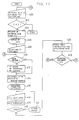
- the microcomputer 78 has a software which will be explained hereinunder with reference to Fig. 4.
- Step l52 the operator decides whether it is necessary to load the microfilm l6, i.e.,whether is is necessary for inputting the command data while observing the image on the screen 30. If the loading is necessary, the operator loads the microfilm l6 in Step l54.
- the user need not load the microfilm.
- the loading is often necessary in the case where the microfilm is a conventional film which has been fabricated without specific consideration for digital recording purpose.
- Step l56 He can choose either a data forming mode for forming a new command data in the floppy disk 38 and an updating mode in which command data already stored in the floppy disk 38 is updated or supplied with additional information.
- Step l58 formatting of the floppy disk 38 is conducted in Step l58. meanwhile, the operator selects the type of the microfilm l6 and the frame retrieval mode, upon consultation with the menu displayed on the CRT display 36.
- the frame retrieval mode includes, referring to Fig. 3, a mode for appointing the frame by counting the number of the page blip marks and a mode in which the frame is appointed by counting first the number of the file blip marks l24 and then adding the number of the page blip marks counted after the final file blip mark l24.
- the method for retrieving the data for searching out the frame to be projected is determined in accordance with the type of the microfilm l6 and the selected frame retrieval mode. These initial setting data is written in the RAM 90 through the keyboard. In case of the updating mode, however, the initial setting data is read from the floppy disk 38 and then written in the RAM 90.
- Step l60 an operation is conducted for appointing the address of the frame to be converted and recorded in the optical disk 54 in accordance with the optical disk 54. It is possible to appoint a plurality of frames at a time.
- the address or addresses thus appointed constitute part of the reading data.
- Step l62 When the microfilm l6 has been loaded on the microfilm reader 28 (Step l62), it is possible to conduct a retrieval for seeking the frame of the address which was appointed in Step l60. When this frame has been seeked in Step l66, a judgment is conducted in Step l68 so as to project the image on the screen 30.
- the check for the presence of the appointed frames may be conducted collectively in a later-mentioned Step l80.
- Step l70 the operator visually checks the projected image and inputs the following reading data which is necessary for the microfilm scanner 40 to read the image.
- the reading data includes the following classes of data.
- the image on the microfilm is upright or turned sideways, depending on whether the photographed original is of A4 or A3 size, as will be seen from Fig. 3. Before converting the image data into optical disk file data, therefore, it is necessary to appoint the area to be covered by the microfilm scanner 40.
- the reading resolution is switchable between 8 dot/mm and l6 dot/mm by means of a resolution change-over circuit ll2 shown in Fig. 5.
- the threshold value is used for discrimination of each pixel data between white and black, in a binary coding circuit l08 which is shown in Fig. 5.
- the manual mode is selected, the user is required to input also the threshold value.
- the binary coding is specifically mentioned, this is not exclusive and the image processing method of the invention can be applied also to the case where tone gradation is employed.
- the above-mentioned three modes i.e.,the automatic mode, manual mode and locking mode, can also be applied to the case where tone gradation is employed.
- the manual mode is selected, the user is required also to input the value of tone, e.g., thin or thick, in accordance with the density of the original image.
- the reading area can be set either in trimming mode in which the area to be set is read and masking mode in which the area which is not to be read is appointed. Thus, the area to be read is input either through the trimming or the masking mode.
- unit file is used here to mean a group consisting of at least one complete document, i.e., a document or a group of documents in which the final document is not incomplete.
- one document means the range between adjacent file blip marks l24 shown in Fig. 3, which corresponds to one complete document such as a single patent specification.
- Step l66 a judgment is conducted as to whether the frame of the address appointed in Step l60 has been found in Step l64. If not, the process proceeds to Step l74 in which a sign indicative of address appointing failure is put on the CRT display 36. The process then returns to Step l60 so ad to allow the user to re-enter the address.
- Step l76 the operator inputs a retrieval data such as a key word necessary for enabling the user to search for the image after the digital recording in the optical disk 54.
- the key word is given for each document, and each document can be provided with a plurality of key words. When each document can be identified by any of a plurality of key words, the user can make access to this document from various aspects of the document.
- Step l80 When the microfilm l6 has been loaded on the microfilm reader 28 (Step l78), a check is done in Step l80 for the content of the reading data input in Step l70, while conducting frame feed of the film. The check is conducted for each of the following points.
- Retrieval is conducted through the microfilm to check whether frames corresponding to the addresses on the microfilm appointed in Step l60 exist.
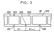
- the distance X (see Fig. 3) between the page blip mark l22 of the frame which is being projected and the blip mark l22 of the immediately preceding frame is measured.
- the distance X is compared with the width of the image determined by the reading size which has been input in Step l70, thus enabling determination as to whether the input reading data is adequate.
- the measurement of the distance X between the blip marks l22 is conducted by counting the pulses from the pulse generator 74.
- Adequate range of the threshold value has been beforehand stored in the ROM 88, and the check is conducted by judging whether the threshold value set in Step l70 falls within this range.
- the maximum readable area of the image frame is determined on the basis of the distance between page blip marks l22, and a judgment is conducted to determine whether the reading area set in Step l70 falls within the above-mentioned maximum readable area.
- Step l82 If the check conducted in Step l82 has proved that the input contains no error, and if it has proved in Step l84 that the input of the command data has not been completed for all the frames to be converted, the process returns to Step l60 in which the input operation is conducted once again.
- Step l82 determines whether the input contains any error. If the check in Step l82 has proved that the input contains any error, the content of the error is displayed on the CRT display 36, and the process returns to Step l60 or l70 so as to allow the operator to correct the input.
- the Step l60 is executed when the kind of the error is such one that requires again the retrieval of the image frame recorded in the microfilm.
- Step l84 a judgment is conducted as to whether the input of the command data through the keyboard 34 has been completed. If the answer is YES, the process proceeds to Step l88 in which the command data stored in the RAM 90 is transferred to and recorded in the floppy disk 38 through the floppy disk driver 84. Obviously, when the updating mode has been selected in Step l56, updating and addition of data is conducted when the command data is recorded in the floppy disk 38.
- Step l90 the operator takes the microfilm l6 and the floppy disk 38 from the microfilm reader 28, thus completing the operation for recording the command data in the floppy disk 38.
- Step l80 shown in Fig. 4 is executed after mounting of the microfilm l6 on the microfilm reader 28.
- an answer YES is given to the question posed in Step l84.
- Fig. 4 shows, by way of example, a process in which the step of forming the command data and the step of checking the command data are impartible parts of a step. This, however, is not exclusive and the process may be such that the formation of the command data and the checking of the command data are executed as separate steps. In such a case, the formation of the command data may be conducted without employing the microfilm, while the checking is executed by employing th microfilm.
- the projection of the image of image onto the line sensor 42 and the screen 44 is conducted by rotating a mirror 92.
- the line sensor 42 is pre-scanned by means of a pre-scanner 98 which is adapted for horizontally scanning the projected image by means of a motor 96.
- An automatic exposure sensor l00 is disposed to direct towards the path of the projected light rays.
- the exposure sensor is adapted for detecting the quantity of light which has been transmitted through the film, and delivers the result of the detection to the input port 80 through an A/D converter l02.
- the signal from the automatic exposure sensor l00 is used for the purpose of controlling the mechanism (not shown) for adjusting the light quantity or for the purpose of controlling the lamp voltage so as to adjust the total light quantity output.
- the line sensor 42 is composed of, for example, a CCD which is adapted to conducting main scanning in accordance with pulses from a main scan and reading circuit l04. Electric charges corresponding to the quantity of light received by the element of the line sensor 42 are successively delivered to the main scan and reading circuit l04. The charges are then converted into voltages and supplied to an A/D converter l06 so as to be converted by the latter into digital values.
- the digital signals output from the A/D converter l06 is supplied to a binary coding circuit l08 and is converted either into a value "l” or a value "0" upon comparison with the threshold value from the microcomputer 78A. The thus obtained binary signal is then supplied to a line buffer ll0 in a bit-by-bit manner.
- the operation is as follows.
- the data corresponding to two lines is supplied to the line buffer ll0, the data is transferred to a resolution change-over circuit ll2, so that the resolution is changed from l6 dot/mm to 8 dot/mm in accordance with a change-over signal from the microcomputer 78A.
- the binary-coded data is supplied to the file controller ll4 through an interface ll4.
- the exchange of data between the file controller 4l and the microcomputer 78A is conducted through the intermediary of an interface ll8.
- the microfilm scanner 40 is adapted for operating in accordance with a control command supplied thereto from the file controller 4l through the interface ll8.
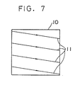
- This software is adapted for scanning the original l0 at a predetermined interval along a plurality lines (scan lines ll) of scan, and examines the degree of density of the whole area of the original by making use of the result of the scan as samples, and determines the threshold for the binary coding in accordance with the result of examination of the degree of density.
- the software then allows the image to be recorded in the optical disk 54.
- the software serves to inform the operator of this extraordinary state by displaying a sign indicative of the extraordinary state or by generating an alarm sound. The operator informed of the extraordinary state then determines whether the extraordinary image is to be skipped over o to be recorded in the optical disk.
- This process is intended for determination of the threshold value and, hence, is conducted during preparatory scanning in advance of reading of the image data.
- the preparatory scanning is effected by the microfilm scanner 40 in accordance with the reading command given by the file controller 4l.
- it is required to consecutively read successive images and to determine the threshold value for each of the images in accordance with the degree of density of image on each image. In such cases, it is advisable to arrange such that the preparatory scanning is conducted during returning scan of the line sensor after the designated film frame is reached.
- Step 300 the floppy disk 38 reads the command data and transfers the same to the RAM 90A. Then, the process proceeds to Steps 30l, 302 in which the value of a number i , which represents that the present sampling of image density is i-th sampling, is initialized to 0 (zero). Then, the process further proceeds to Step 304 in which the address of the frame to be converted is read out of the command data and the roll microfilm l8 is shifted such as to bring this frame to the position confronting the pressing glass mechanism 64. The image of the image in this frame is then projected onto the screen 44.
- Step 305 the positions of the scan lines ll and the number N of the pixels to be sampled are determined in accordance with the reading size data and the reading area data which are included in the command data.
- Step 306 the pre-scan mechanism 98 is operated at a speed which is higher than that in the conversion into the optical file.
- Step 3l7 an incrementary operation for replacing i with i + l is conducted in Step 3l7,and the process returns to Step 308 so that the above-described operation is repeated.
- the difference between the maximum density D MAX and the minimum density D MIN usually becomes greater than the predetermined value ⁇ .
- Step 325 the threshold value for discrimination between white and black is determined in accordance with the known method.
- the process then proceeds to Step 326 in which the line sensor 42 is moved at high speed to the starting position for reading the image.
- This starting position is determined by the command data stored in the RAM 90A.
- the line sensor 42 is moved to the starting position.
- the process proceeds to Step 328 in which the line sensor is moved to scan the image on the frame to be converted, so as to read the image on this frame on the basis of the threshold valued determined in Step 325.
- the image is red digitally and the thus obtained digital image data is delivered to the file controller 4l through the interface ll4.
- the file controller 4l then operates to record the digital image data in the optical disk 54.
- the file controller 4l operates to allow the retrieval key items included in the command data delivered from the floppy disk 38 to be recorded in the optical disk 54 and the floppy disk 55.
- the process judges that the present frame carries no image.
- the number N is set to be 4 times as large as the number of pixels included in each line. If it is judged that the present frame carries no image, the process proceeds from Step 308 to 330 in which a signal indicative of an abnormality in the image is delivered to the file controller 4l through the interface ll8, so as to enable the CRT display 58 to display information representing the abnormality. The process then proceeds to Step 332, in which the system is ready for keyboard operation which is to be conducted by the operator who watches the image image projected on the screen 44, as well as the indication on the CRT display.
- the means for informing the operator of the abnormality may be constituted by other means than CRT display.
- alarming sound can effectively be used as the means for informing the operator of the abnormality.
- the arrangement also may be such that two modes are available in the event of any abnormality: namely, a mode in which the system waits for any instruction which may be given by the operator and a mode in which the system automatically processes the next image while skipping over the image having abnormality.
- the operator can promote the process to Steps 334, 325 and then 326 so as to enable the system to conduct ordinary image processing routine, by pressing an image recording key on the keyboard 56.
- Step 334 the process can be returned from Step 334 to Step 30l, thus skipping over the frame in question. In consequence, this frame is not recorded in the optical disk 54.
- This step also enables the operator to find any wrong appointment of the readable area. Namely, if the area of the microfilm having no image has been appointed wrongly though the frame has an image, the operator can be informed of the wrong appointment through the CRT display or the alarming sound.
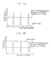
- Figs. 8A and 8B show the quantity of light received by a light-receiving element of the line sensor 42 as observed when the microfilm l6 is scanned by the line sensor 42 when the microfilm l6 is of negative type and positive type, respectively.
- the system judges that the frame has a certain image, when the number of peaks of levels above a predetermined level exceeds a predetermined percentage. Conversely, when the number of such peak values is zero or below the above- mentioned predetermined level, the system judged that the frame has no image.
- the discrimination between the negative type and positive type is conducted through judging whether the base level if below or above a predetermined level. More specifically, when the base level is below the predetermined level, the image is judged as being a negative image, whereas, if not, the image is judged as being a positive image.
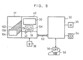
- This image processing apparatus is designed for recording, in an optical disk 5A as a digital recording medium, the image selected in accordance with designated retrieval data from among images recorded in a roll microfilm as an analog recording medium.
- An auto-stocker 27 stocks cassette films l5A, l5B and l5C..and enables an appointed cassette film l5K to be automatically picked up and loaded on a microfilm scanner 40.
- the microfilm scanner 40 As the cassette film is loaded on the microfilm scanner 40, the image on the roll microfilm l8 in the cassette film l5, just positioned at the reading position, is projected on a screen 30 and is read by means of a line sensor 42 and then binary-coded.
- the microfilm scanner 40 is adapted to be loaded with a floppy disk 38 which serves as a first retrieval data recording medium.
- the floppy disk 38 stores first retrieval data such as keywords and second retrieval data such as Vol. No., Document No., address of the first frame of the document, and so forth, as well as other related data such as the title, size of original from which the micro image is formed, number of pages of document, and so forth.
- the microfilm scanner 40 is connected to a file controller 52 through a signal line 50.
- the file controller 52 is adapted to be loaded with an optical disk 54 and a floppy disk 55 which serves as a second retrieval data recording medium.
- the arrangement is such that the image data read by the line sensor 42 is recorded in an optical disk 54, and the first retrieval data of the thus read image is recorded in the optical disk 54 and the floppy disk 55.
- a keyboard 58 and a CRT display 56 are connected to the file controller 52. The operator can deliver to the microfilm scanner 40 and the file controller 4l the retrieval data concerning the image to be file-converted, by suitably operating the keyboard 58 in accordance with instructions given on the CRT display 56.
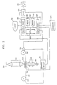
- the construction of the microfilm scanner 40 will be described hereinafter with reference to Fig. l0.
- the roll microfilm l8 carrying micro-images recorded thereon is taken-up by a supply reel as a motor 59 is driven,whereas, when a motor 6l operates, the roll microfilm is taken up by a take-up reel 62A.
- the angle of rotation of the take-up reel 62A is detected by a pulse generator 63.
- the roll microfilm l8 carries page blip marks l22 along the lower edge thereof at positions corresponding to the frames l20 and file blip marks along its upper edge for indicating the boundary between adjacent frame blocks each having a plurality of frames related to each other.
- the address of the frame l20 can be detected by continuously counting the page blip marks l22 and the file blip marks l24. These blip marks l22 and l24 are sensed by a blip mark sensor 76A shown in Fig. l0.
- the signal from the blip mark sensor 76A is delivered to a CPU through an input port 80A and is output from the latter as a motor drive control signal to a drive circuit 72A through an output port 82A, whereby the motors 59 and 6l are controlled so that the designated frames is brought to the reading position.
- the image carried by the roll microfilm and positioned at the reading position is projected onto the line sensor 42.
- the line sensor 42 is adapted to be driven by a pre-scan mechanism 98 so as to effect a horizontal pre-scan over the projected image.
- the line sensor 42 is composed of, for example, a CCD and is adapted for effecting a main scan in accordance with pulses transferred from a main scan/reading circuit l04, so that electric charges in amount corresponding to the quantity of light received by the elements of the line sensor 42 are successively supplied to the main scan/reading circuit l04.
- the thus supplied charges are converted into voltage and supplied to an A/D converter l06.
- the signal converted into the digital signals by the A/D converter l06 are delivered to a binary coding circuit l08 which is constituted by a digital comparator, so as to be converted into a signal of "l" or "0"level through a comparison with a threshold value supplied from a microcomputer 78A.
- the thus obtained binary signal is supplied to a line buffer ll 0 in a bit-by-bit manner.
- the operation for switching the resolution is as follows.
- the data corresponding to two lines is supplied to the line buffer ll0, the data is delivered to a resolution switching circuit ll2 and a switching is conducted by this circuit from a resolution of l6 dots/mm to 8 dots/mm in accordance with switching instructions given by a microcomputer 78A.
- the binary-coded data is supplied to the file controller 4l through an interface ll4.
- the exchange of the control signal and data between the file controller 4l and the microcomputer 78A is conducted through another interface ll8.
- the floppy disk 38 is loaded on a floppy disk driver 95 so that the first retrieval data, second retrieval data and relates data recorded in the floppy disk 38 are read by the microcomputer 78A.
- the floppy disk 38 and the floppy disk driver 95 are provided on the same side of the system as the microfilm scanner 40. Needless to say, however, the floppy disk 38 and the floppy disk driver 95 may be provided on the same side as the file controller 4l.
- Thew digital signals corresponding to the image read by the microfilm scanner 40 is sent to the file controller 4l through the interface ll4 and is stored in a digital recording medium which is in this case an optical disk 54.
- the first retrieval data and also the related data as required are stored in the optical disk 54.
- Third retrieval data such as the No. of the optical disk 54, No. of the document in the file stored in the optical disk 54 and the address of the leading frame of the document are determined when the digital signals corresponding to the read image are recorded in the optical disk 54. Then, the first retrieval data and the third retrieval data are recorded in a floppy disk 55 which serves as the second retrieval data recording medium.
- Fig. ll shows a flow chart.
- Fig. l2A shows the data recorded in the floppy disk 38, i.e., the first retrieval data (keywords), second retrieval data (Vol. No., document No. and address of the leading frame) and related data
- Fig. l2B shows the first retrieval data (keywords)
- third retrieval data disk No., document No., address of document in optical disk
- the keywords as the retrieval data are illustrated in a simplified form for the purpose of easiness of understanding.
- Step 400 the operator operates the keyboard 58 so as to input the keyword of the document which is to be converted from the microfilm file to the optical disk file.
- the keyword is represented by "A" hereinunder.
- the process proceeds to Steps 402 and 404 unless a key operation of finishing the processing is executed in Step 400.
- the keyword A and a keyword retrieval command are delivered to the microfilm scanner 40.
- the microfilm scanner 40 picks up documents which include the keyword A from the floppy disk 38.
- three documents: namely, PA, QA and RA are picked up.
- Step 406 the picked up first retrieval data, second retrieval data and the related data, as well as display command, are delivered from the microcomputer 78A to the file controller 4l.
- the CRT display 56 displays the picked up data so that the operator can confirm the displayed data and select the document to be file-converted through a key operation. It is assumed here that all the displayed documents PA, QA and RA are selected by the operator.
- the file controller 4l then delivers to the microfilm scanner 40 the second retrieval data of the selected documents and retrieval command. Amongst the there selected documents, the document PA is first sent to Step 4l0 for digital conversion.
- the CPU 86A compares the Vol. No.”03" constituting the first data of the second retrieval data with the Vol.No.
- the auto-stocker l2 furnishes the cassette film of Vol. No. 3 and loads it on the microfilm scanner l4.
- Step 4l4 the,motor 6l is started so that the roll microfilm l8 is taken-up by the take-up reel 62A. Meanwhile, the blip mark sensor 76A counts the file blip marks l24. The motors 59 and 6l are controlled such that the count value becomes "5" so that the first frame image of the document No. 5 is brought to the reading position. It is also possible to locate the first frame of the document No. 5 at the reading position by counting the page blip marks l22 and driving the motors 59 and 6l such that the count value becomes "l0l". In Step 4l6, the image located at the reading position is projected on the screen 30.
- Step 4l8 the operator confirms this image and operates the keyboard 58 so as to input reading data necessary for reading the image by the line sensor 42.
- the reading data are, for example, as follows: (l) reading size, (2) reading resolution, (3) black/while judging threshold, (4) reading area, (5) polarity of image
- Step 420 the content of the reading data input in Step 4l8 is checked for any error.
- the error check includes, for example, the following checking items:
- Step 422 a judgment is conducted as to whether any input error exists. In case of any error being exist, the content of the input error is displayed on the CRT display 56 in Step 424. The process then returns to Step 4l8 and the reading data is input again. If there is no error, the process proceeds to Step 426 in which a mirror 92 is rotated so as to project the image onto the line sensor 42, and the motor 96 operates to allow the image data to be read in accordance with the reading data. The thus read-out image data is sent to the file controller 4l together with the recording command. The file controller 4l then operates to record the image data in the optical disk 54.
- the first retrieval data (keyword)
- the third retrieval data (disk No., document No., document address in optical disk) and related data, all of which are shown in Fig. l2B, are recorded in the optical disk 54 and the floppy disk 55.
- the third retrieval data is for identifying and retrieving the documents recorded in the optical disk 52 and is recorded in a certain relation to the first retrieval data (keyword).
- the recording of these data in the floppy disk 55 is intended for enhancement of the retrieving speed.
- the recording of these data in the optical disk is intended for back-up: namely, for making it possible to record these data in a new floppy disk 55 in the event that the floppy disk 55 is lost or the retrieval data recorded in the floppy disk 55 is broken.
- the data are recorded in the optical disk 54.
- This, however, is not exclusive and the optical disk may store only such data that have to be stored in this disk. It is preferred to arrange such that the related data which are stored in predetermined areas amongst all related data, e.g., Title and the Document Size, are recorded also in the floppy disk 55 as related data. Such an arrangement will eliminate laborious work for inputting these related data.
- Step 428 the file conversion for the documents QA and RA have not been completed yet, so that the answer is NO and the process returns to Step 4l0.
- the steps 4l0 to 426 are cyclically executed so that the documents QA and QR are recorded in the optical disk 54.
- the document RA is recorded in a cassette film l5 of a different Vol. from that storing the document QA, so that n answer NO is given to the question in Step 4l0, thereby initiating the operation for changing the cassette film.
- the file controller 4l is provided with a buffer memory which is capable of temporarily storing the image data delivered through the interface ll4. Therefore, the operation of Steps 4l0 through 428 and the process for recording of the image data in the optical disk 54 performed by the file controller 4l are conducted simultaneously.
- the manual input through the keyboard 58 for directly inputting the address of the document on the roll microfilm is not necessary. This in turn eliminates any input error and makes it possible to convert all the relevant images.
- the input operation is very easy because the operator is required only to input a predetermined keyword as the retrieval data for making access to the desired documents.
- the keyword "A: is appointed so that three documents including the keyword "A” are extracted.
- This is only illustrative and can be modified in various manners. For instance, it is possible to input and use, as the first retrieval data, a logical product (AND) or logical sum (OR) of keywords.
- the first retrieval data in the described embodiment is constituted by a keyword
- the first retrieval data may be constituted by other data such as AND of the Vol. No. and the document No. or, in case of Patent publications, Patent No. or other particular item.
- any data which can suitably be used in the retrieval of the document or image can be used as the first retrieval data.
- the input first retrieval data can be used directly as the second retrieval data.
- the first and the second retrieval data may be the same.
- the floppy disks used as the first and second retrieval data recording medium in the described embodiment may be substituted by other types of recording medium such as hard disks depending on conditions such as storage capacity.
- the first retrieval data is manually input through the keyboard 58.
- the arrangement may be such that the first retrieval data is beforehand stored in a floppy disk by means of, for example, a personal computer or the like and is read by the file controller 52. It is also possible to arrange such that the first retrieval data is transmitted from an external device and is received by the file controller 52 or by the microfilm scanner 40.
- the whole or part of the reading data may be added to the data recorded in the first retrieval data recording medium.
- the reading data are checked each time the file conversion is conducted.
- the reading data may be formed beforehand so as to simplify the input operation thereby improving the efficiency of the work.
- the second retrieval data containing the first retrieval data, as well as related data is searched out from the first retrieval data recording medium, and the image on the analog recording medium is moved to the reading position in accordance with the second retrieval data.
- the image is then read by the image sensor and is recorded in the digital recording medium.
- the third retrieval data for enabling the image on the digital recording medium to be retrieved is recorded in the second retrieval data recording medium, it is not necessary to take labor of inputting the data for retrieving the digital image.
- the input operation is simplified and facilitated and it becomes possible to quickly record the image carried by the analog recording medium onto the digital recording medium.
- the recording medium for recording the command data may be constituted by various suitable means capable of temporarily storing data, such as a magnetic tape, a paper tape, and a RAM with back-up battery, although floppy disks are specifically mentioned.
- a magnetic tape such as a magnetic tape, a paper tape, and a RAM with back-up battery
- the microfilm used as the analog recording medium in the described embodiments are only illustrative, and various other mediums capable of being handled continuously, e.g., a paper sheet fed by an automatic feeder, may be used as the analog recording medium.
- the reading of analog image is conducted by enlarging the analog image and then reading the enlarged image by a sensor.
- the enlargement of the analog image is not essential. Namely, in some cases, the analog image is contracted and then read by the sensor. It is even possible to read the analog image by the sensor while keeping the sensor in close contact with the analog image.
- the digital recording medium may be constituted by any medium which can store digital signals, although optical disks are specifically mentioned in the description of the embodiments.
- the digital recording medium may be, for example, a magnetic tape.
- the method and the apparatus of the invention may be carried out also in such a manner that the microfilm reader 28 incorporates an area sensor so as to directly read the image projected onto the area sensor.
- an area sensor so as to directly read the image projected onto the area sensor.
- an image recorded on an analog recording medium is read and then recorded in a digital recording medium by employing two independent steps: namely, a step for recording, in a command data recording medium, command data concerning the image to be recorded, and a step for recording the image in the digital recording medium by reading the image in the analog recording medium in accordance with the command data read from the command data recording medium.
- two steps are independent of each other, and partly because the speed at which the command data is read out from the recording medium is much higher than the speed at which the operator manually inputs such command data, it is possible to convert a large number of analog images into digital data and to store the same in the digital recording medium consecutively at a distinguished high speed.
Abstract
Description
- The present invention relates to an image processing method and apparatus and, more particularly, to an image processing method and apparatus in which an image or an image recorded in an analog recording medium such as a microfilm, paper or the like is read and then processed digitally so as to be recorded in another recording medium of digital type such as an optical disk or a magnetic tape.
- In general, office automation facilities, particularly for filing, are required to meet the following demands:
- (l) High-speed input of a lot of information
- (2) High-speed reproduction
- (3) Validity as means of legal documentation
- (4) Long-term storage capability
- (5) Standardization of recording medium
- (6) High resolution
- (7) High recording density
- (8) High retrieval speed
- (9) Linkage with communication network
- (l0) Capability of providing instantaneous availability (For example, capability for enabling reading of data immediately after writing, without necessitating development or fixing)
- (ll) Ease of updating of data
- In general, microfilms have been recognized as filing means which cope with demands (l) to (7) above, whereas optical disk files are superior in that they meet the demands (7) to (ll) above. Proposal has been made, therefore, for a composite filing system in which a microfilm filing system and an optical disk filing system are combined with each other. Such a composite filing system, which may be referred to as optical-microfilm composite filing system, is capable of coping with all the demands (l) to (7) above, because both the advantages of the microfilm filing system and the advantages of the optical disk filing system can be enjoyed. Examples of such composite systems are required, for example, in Information Media & Technology Volume l7 No. 3, pp 97-99, Information Media & Technology Volume l8 No. 3 pp lll-ll4 and Reprographics Quarterly, Vol. l6, No. 4 pp l4l-l49, as well as in Japanese Patent Laid-Open Nos. 64855/l984, 63860/l984 and 74l44/l986 et al.
- Microfilm filing system also is suitable for forming data image in confidence because the user can take a photo of an original data with a camera without requiring the original to be transported outside of, for example, a room. This advantage, together with the features of the microfilm set forth as (l), (3) and (4) above, leads to an idea that the recording of images which require high degree of confidence or images which are allowed to be brought out only for a short time would be carried out successfully if the original image data is first recorded in a microfilm and then the recorded image is read by means of a microfilm scanner the output of which is digitally processed so as to be recorded in an optical disk recording apparatus.
- Such a method, however, suffers from a disadvantage in that, since the optical disk file does not allow the user to visually inspect the content of the record, the operator has to conduct a manual work for inputting retrieval data, when converting the microfilm file into optical disk file. The operation for reading an image and recording the same in an optical disk requires the operator to set various reading data necessary for the purpose of reading the image, such as the readable area of frame of microfilm, resolution with which the image is converted into digital data, e.g., 8 dots/mm, l6 dots/mm and so forth, and threshold for allowing discrimination between black and white. In consequence, the speed of conversion from microfilm data into optical disk data has been impractically low. In fact, it takes about 8 hours for converting 500 pages of images. In addition, services of the optical disk recording apparatus such as retrieval and printing are not available during the manual work for converting the microfilm file into the optical disk file. In consequence, the rate of operation of the expensive optical disk recording apparatus is impractically low.
- Accordingly, an object of the present invention is to provide an image processing method and apparatus which are capable of continuously reading image data on an analog medium and digitally recording the thus read image data in a digital recording medium.
- To this end, according to one aspect of the present invention, there is provided an image processing method for reading an image recorded in an analog recording medium and then recording the read image digitally in a digital recording medium, the method comprising: (a) a command data recording step in which command data which includes a retrieval data for enabling retrieval of the image to be recorded in the digital recording medium and a reading data for allowing the image recorded in the digital recording medium to be read is input and recorded in a command data recording medium; and (b) a digital image recording step in which, independently of the command data recording step, the command data is read from the command data recording medium, and the images recorded in the analog recording medium are read in accordance with the command data so as to be recorded digitally in the digital recording medium.
- According to another aspect of the invention, there is provided an image processing method for reading an image recorded in an analog recording medium and then recording the read image digitally in a digital recording medium, the method comprising: a command data forming step in which command data which includes a retrieval data for enabling retrieval of the image to be recorded in the digital recording medium and a reading data for allowing the image recorded in the digital recording medium to be read is input and formed in a command data recording medium; and a digital image recording step in which, independently of the command data recording step, the command data is read from the command data recording medium, and the images recorded in the analog recording medium are read in accordance with the command data so as to be recorded digitally in the digital recording medium.
- A description will be made hereinunder as to the meaning of the "command data".
- The command data is composed of a retrieval data and reading data. The retrieval data is the data which is used for the purpose of retrieving image data to be recorded in the digital recording medium, and usually has the form of key items or key words. The reading data is the data which is necessary for reading the image from the analog recording medium. For instance, the reading data includes various data such as the address of the image in the analog recording medium, threshold for discrimination between black and white necessary for digitalizing the tone of the image, threshold value for half tone, resolution, and area to be read from one frame of image.
- The step of forming the command data and the step of forming the digital image recording step are conducted independently. In addition, the command data formed on the command data recording medium is read at a speed which is much higher than the speed at which the command data is recorded in the command data recording medium by manual work of the operator.
- It is therefore possible to digitally record a large quantity of analog image data into a digital recording medium consecutively at once.
- These and other objects, features and advantages of the present invention will become clear from the following description of the preferred embodiments when the same is read in conjunction with the accompanying drawings.
-
- Fig. l is a schematic illustration of a file conversion system to which the present invention is applied;
- Fig. 2 is a schematic illustration of a microfilm reader incorporated in the system shown in Fig. l;
- Fig. 3 is an illustration of th relationship between frames of a roll microfilm and a blip mark;
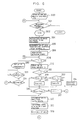
- Fig. 4 is a flow chart illustrating the construction of a part of software of a microcomputer;
- Fig. 5 is a schematic illustration of a microfilm scanner incorporated in the system shown in Fig. l;
- Fig. 6 is a flow chart showing the constructions of parts of a microcomputer and a file controller;
- Fig. 7 is an illustration of lines of scanning of pixels which are used as reference for judgment as to whether all the pixels have an identical density; and
- Figs. 8A and 8B are diagrams illustrating quantity of lights received by a light-receiving element of a line sensor as obtained when an image is scanned with the line sensor, when the image is a positive image and when the image is a negative image, respectively;
- Fig. 9 is a schematic illustration of a second embodiment;
- Fig. l0 is a block diagram of a microfilm scanner used in the embodiment shown in Fig. 9;
- Fig. ll is a flow chart showing the flow of the second embodiment;
- Fig. l2A is a table showing first and second retrieval data and related data stored in a floppy disk; and
- Fig. l2B is a table showing first and third retrieval data and related data stored in an optical disk.
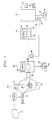
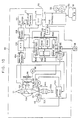
- The outline of a file conversion system to which the present invention pertains will be explained hereinunder with specific reference to Fig. l.
- A camera l2 picks up the image of an original l0. A microfilm in the camera is then subjected to a treatment process l4 in which are conducted development, fixing and rinsing, so that a microfilm l6 carrying a readable image is obtained. Various types of film are usable as the microfilm l6, such as l6 mm roll microfilm l8, 35
mm roll microfilm 20,microfish 22, aperture card and so forth. - The photographing operation is conducted wherever the original l0 is placed, because the camera l2 has a high degree of portability. That is, the need for conveying the original outside is eliminated so that the original can be handled in confidence and is prevented from being missed. Even if the original is brought outside, it can be returned in a very short time because the photographing can be completed without requiring substantial time. Namely, the photographing can be conducted in a very high speed, say 5,000 to l0,000 images per 8 hours, which is about l0 to 20 times as high as the speed at which images are directly read and recorded in an optical disk by a scanner. Thus, the operator can return the original in a very short time. The microfilm enables the user or operator to visually check its content so that he can input the retrieval data even after the photographing. In contrast, the image recorded in an optical disk cannot be visually checked, so that the retrieval data has to be input simultaneously with the recording of the image. Furthermore, the microfilm has a high credibility as means of legal documentation and capability for storing data for long time.
- Therefore, it would be advantageous to take images of all original and then convert and record only the necessary images into digital disk file, rather than to directly record images of all the images in the optical disk file. The microfilm l6 is loaded in a
kit 26 specifically designed to match with the type of the microfilm, and is placed in amicrofilm reader 28. Themicrofilm reader 28 has a screen on which the images of the images on the microfilm are projected. The frame feed of the microfilm l6 is conducted by, for example, an input signal input through akeyboard 34, and data such as the frame address is displayed on aCRT display 36. The operator, while watching the image projected on thescreen 30 or looking into a memo, inputs the command data, e.g., retrieval data and reading data, relating the image to be converted and recorded into the optical disk file. The command data is displayed on a CRT display, for a visual check for any error. After correction of error, if any, the recording instruction data is recorded in afloppy disk 38. - Conversion of the microfilm file into an optical disk file is conducted automatically and consecutively, independently of the above-described manual work. Namely, the
kit 26 and thefloppy disk 38 after completion of the process conducted by themicrofilm reader 28 is loaded in amicrofilm scanner 40 and a file controller 4l. The images on the microfilm l6 in thekit 26 are projected onto ascreen 44 and are read by aline sensor 42. The thus read images are then digitalized and delivered to the file controller 4l of the opticaldisk recording apparatus 52 through adata line 50. Thefloppy disk 38 is then loaded in the file controller 4l so as to be read by the latter, and the thus read data is delivered to themicrofilm scanner 40 through thedata line 50. Upon receipt of this data, themicrofilm scanner 40 conducts various operations such as the film feed of the microfilm l6, projection of image and digitalizing operation, all of which have been described already. The digital image data from themicrofilm scanner 40 and the retrieval data from thefloppy disk 38 are processed by the file controller 4l and recorded in theoptical disk 54. The retrieval data is recorded in a recording medium which is independent from the optical disk, e.g., in afloppy disk 55, and is used for the purpose of high-speed retrieval of data in the optical disk file. The recording instruction data and the digital image data are respectively displayed on aCRT display 56 so as to be monitored. Operation signals such as those for starting and stopping the operation are delivered to the file controller 4l through akeyboard 58. Typically, themicrofilm reader 28, which is comparatively less expensive, may be installed in each of a plurality of offices, while the optical disk recording apparatus which is generally expensive is installed in the head office. - The construction of the
microfilm reader 28 will be described hereinunder with reference to Fig. 2. - In the illustrated example of the
microfilm reader 28, the microfilm l6, which is a roll microfilm l8, is extracted from asupply reel 60 and is taken-up by a take-up reel 62. The intermediate portion of the roll microfilm extracted from thesupply reel 60 is clamped by apressing glass mechanism 64, so as to prevent the image projected on thescreen 30 from being distorted. Light rays from alight source 66 is applied to the roll microfilm l8 through acondenser lens 68 and is transmitted through the roll microfilm l8 so as to project the image of the image on the roll microfilm l8 onto thescreen 30 through a focusinglens 70. - The
supply reel 60 and the take-up reel 62 are driven by motors which operate in response to drive signals given by adrive circuit 72. The rotation of the take-up reel 62 is detected by apulse generator 74 which outputs one pulse for each rotation of thereel 62 through a predetermined small angle. - Simultaneously with the photographing of the original l0, page blip marks l22 corresponding to the respective frames l20 and the blip marks representing the border between the adjacent frame blocks are recorded by exposure on the edge portions of the film corresponding to the respective frames, as shown in Fig. 3. The addresses of the frames l20 can be detected by counting the page blip marks l22 and the file blip marks l22. As will be seen from Fig. 3, the page blip mark l22 and the file blip mark l24 are detected by a pair of blip mark sensors (photosensors) 76.
- The signals from the
pulse generator 74 and theblip mark sensors 76 are supplied to theinput port 80 of amicrocomputer 78 the output port of which delivers the motor control signals to thedrive circuit 72 mentioned before. The operator operates thekeyboard 34 while watching the images projected on thescreen 30 or looking into the memo, so as to input record instruction data to theinput port 80. The thus delivered command data is delivered through theoutput port 80 to theCRT display 36 for confirmation purpose. At the same time, theCRT display 36 displays the address of the projected image. Both a control signal and the command data are delivered from theoutput port 82 to afloppy disk driver 84 so that the command data is recorded in thefloppy disk 38. The arrangement is such that the command data which has been stored in thefloppy disk 38 is delivered to theinput port 80 so as to make it possible to effect any addition, insertion, deletion and correction of the recorded data. Themicrocomputer 78 is equipped with aCPU 86,ROM 88 and aRAM 90. TheCPU 86 is adapted for conducting tasks such as inputting and outputting of data in accordance with a program stored in theROM 88, whileRAM 90 provides facilities for temporary storage of the command data and the working area. - The
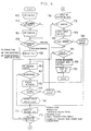
microcomputer 78 has a software which will be explained hereinunder with reference to Fig. 4. - In the first step (Step l52), the operator decides whether it is necessary to load the microfilm l6, i.e.,whether is is necessary for inputting the command data while observing the image on the
screen 30. If the loading is necessary, the operator loads the microfilm l6 in Step l54. - If the command data has been recorded in the form of a memo, the user need not load the microfilm. The loading, however, is often necessary in the case where the microfilm is a conventional film which has been fabricated without specific consideration for digital recording purpose.
- The operator then selects the processing mode in Step l56. He can choose either a data forming mode for forming a new command data in the
floppy disk 38 and an updating mode in which command data already stored in thefloppy disk 38 is updated or supplied with additional information. - When the data forming mode is selected, formatting of the
floppy disk 38 is conducted in Step l58. meanwhile, the operator selects the type of the microfilm l6 and the frame retrieval mode, upon consultation with the menu displayed on theCRT display 36. - Various types of films such as a l6 mm roll microfilm l8, 35
mm microfilm 20,microfish 22 and anaperture card 24 all of which are shown in Fig. l are usable as the microfilm l6. In case of amicrofish 22, it is necessary to input also additional data such as the number of frames in each line and columns and the number of the headers. The frame retrieval mode includes, referring to Fig. 3, a mode for appointing the frame by counting the number of the page blip marks and a mode in which the frame is appointed by counting first the number of the file blip marks l24 and then adding the number of the page blip marks counted after the final file blip mark l24. - The method for retrieving the data for searching out the frame to be projected is determined in accordance with the type of the microfilm l6 and the selected frame retrieval mode. These initial setting data is written in the
RAM 90 through the keyboard. In case of the updating mode, however, the initial setting data is read from thefloppy disk 38 and then written in theRAM 90. - Subsequently, in Step l60, an operation is conducted for appointing the address of the frame to be converted and recorded in the
optical disk 54 in accordance with theoptical disk 54. It is possible to appoint a plurality of frames at a time. The address or addresses thus appointed constitute part of the reading data. - When the microfilm l6 has been loaded on the microfilm reader 28 (Step l62), it is possible to conduct a retrieval for seeking the frame of the address which was appointed in Step l60. When this frame has been seeked in Step l66, a judgment is conducted in Step l68 so as to project the image on the
screen 30. - The check for the presence of the appointed frames may be conducted collectively in a later-mentioned Step l80.
- In Step l70, the operator visually checks the projected image and inputs the following reading data which is necessary for the
microfilm scanner 40 to read the image. - When the microfilm l6 has not been loaded, the operator inputs the reading data upon consultation with the memo in which the command data is beforehand recorded. The reading data includes the following classes of data.
- The image on the microfilm is upright or turned sideways, depending on whether the photographed original is of A4 or A3 size, as will be seen from Fig. 3. Before converting the image data into optical disk file data, therefore, it is necessary to appoint the area to be covered by the
microfilm scanner 40. - The reading resolution is switchable between 8 dot/mm and l6 dot/mm by means of a resolution change-over circuit ll2 shown in Fig. 5.
- The threshold value is used for discrimination of each pixel data between white and black, in a binary coding circuit l08 which is shown in Fig. 5. There are three modes for setting the threshold value: namely, an automatic setting mode in which the threshold value is automatically set in accordance with the result of detection of the quantity of projected light; a manual setting mode in which the operator sets the threshold value upon judging the projected image; and lock mode in which the threshold value is fixed and applied for successive frames. When the manual mode is selected, the user is required to input also the threshold value.
- Although the binary coding is specifically mentioned, this is not exclusive and the image processing method of the invention can be applied also to the case where tone gradation is employed. The above-mentioned three modes, i.e.,the automatic mode, manual mode and locking mode, can also be applied to the case where tone gradation is employed. When the manual mode is selected, the user is required also to input the value of tone, e.g., thin or thick, in accordance with the density of the original image.
- In some cases, it is required to convert only a portion of the projected image into the optical disk file. In such a case, it is necessary to appoint the area to be read. The reading area can be set either in trimming mode in which the area to be set is read and masking mode in which the area which is not to be read is appointed. Thus, the area to be read is input either through the trimming or the masking mode.
- It is also necessary to make a selection between a mode in which the image stored in the microfilm l6 is directly read (positive) or read after reversal (negative) between black and white.
- Setting is also necessary for the number of images or frames to be read under the same conditions (l) to (5), i.e., without requiring any change in the selection or values concerning the condition factors (l) to (5).
- It is of course possible to set the total number of the frames within the range of addresses input in Step l60.
- The process then proceeds to Steps l7l and l72. If inputting of the command data for a unit file has not been completed yet, the steps l60 to l70 are followed again. The term "unit file" is used here to mean a group consisting of at least one complete document, i.e.,a document or a group of documents in which the final document is not incomplete. The term "one document" means the range between adjacent file blip marks l24 shown in Fig. 3, which corresponds to one complete document such as a single patent specification.
- In Step l66, a judgment is conducted as to whether the frame of the address appointed in Step l60 has been found in Step l64. If not, the process proceeds to Step l74 in which a sign indicative of address appointing failure is put on the
CRT display 36. The process then returns to Step l60 so ad to allow the user to re-enter the address. - If the question in Step l72 proved that the reading instruction data has been input on the basis of document units, the process proceeds to Step l76 in which the operator inputs a retrieval data such as a key word necessary for enabling the user to search for the image after the digital recording in the
optical disk 54. The key word is given for each document, and each document can be provided with a plurality of key words. When each document can be identified by any of a plurality of key words, the user can make access to this document from various aspects of the document. - When the microfilm l6 has been loaded on the microfilm reader 28 (Step l78), a check is done in Step l80 for the content of the reading data input in Step l70, while conducting frame feed of the film. The check is conducted for each of the following points.
- Retrieval is conducted through the microfilm to check whether frames corresponding to the addresses on the microfilm appointed in Step l60 exist.
- The distance X (see Fig. 3) between the page blip mark l22 of the frame which is being projected and the blip mark l22 of the immediately preceding frame is measured. The distance X is compared with the width of the image determined by the reading size which has been input in Step l70, thus enabling determination as to whether the input reading data is adequate. The measurement of the distance X between the blip marks l22 is conducted by counting the pulses from the
pulse generator 74. - Adequate range of the threshold value has been beforehand stored in the
ROM 88, and the check is conducted by judging whether the threshold value set in Step l70 falls within this range. - It is also possible to check whether the set threshold value is adequate, by making use of the detected value of the light quantity of the projected light rays.
- The maximum readable area of the image frame is determined on the basis of the distance between page blip marks l22, and a judgment is conducted to determine whether the reading area set in Step l70 falls within the above-mentioned maximum readable area.
- If the check conducted in Step l82 has proved that the input contains no error, and if it has proved in Step l84 that the input of the command data has not been completed for all the frames to be converted, the process returns to Step l60 in which the input operation is conducted once again.
- Conversely, if the check in Step l82 has proved that the input contains any error, the content of the error is displayed on the
CRT display 36, and the process returns to Step l60 or l70 so as to allow the operator to correct the input. The Step l60 is executed when the kind of the error is such one that requires again the retrieval of the image frame recorded in the microfilm. - Although not shown in Fig. 4,input items which require no correction are skipped over during the correction of the defective input.
- In Step l84, a judgment is conducted as to whether the input of the command data through the
keyboard 34 has been completed. If the answer is YES, the process proceeds to Step l88 in which the command data stored in theRAM 90 is transferred to and recorded in thefloppy disk 38 through thefloppy disk driver 84. Obviously, when the updating mode has been selected in Step l56, updating and addition of data is conducted when the command data is recorded in thefloppy disk 38. - Subsequently, in Step l90, the operator takes the microfilm l6 and the
floppy disk 38 from themicrofilm reader 28, thus completing the operation for recording the command data in thefloppy disk 38. - In the process described above, when the microfilm l6 has not been loaded in the
microfilm reader 28, the check of the content of the input command data is conducted visually through the CRT display. The flow for such a visual check, however, is omitted from the drawings. - When it is necessary to conduct a highly precise check of the content of the input command data, Step l80 shown in Fig. 4 is executed after mounting of the microfilm l6 on the
microfilm reader 28. In this case, an answer YES is given to the question posed in Step l84. Fig. 4 shows, by way of example, a process in which the step of forming the command data and the step of checking the command data are impartible parts of a step. This, however, is not exclusive and the process may be such that the formation of the command data and the checking of the command data are executed as separate steps. In such a case, the formation of the command data may be conducted without employing the microfilm, while the checking is executed by employing th microfilm. - A description will be made hereinunder as to the microfilm scanner, with specific reference to Fig. 5. In this Figure, the same reference numerals with suffix A are used to denote the same parts or members as those used in Fig. 2, and detailed description of such parts or members is omitted.
- The projection of the image of image onto the
line sensor 42 and thescreen 44 is conducted by rotating amirror 92. Theline sensor 42 is pre-scanned by means of a pre-scanner 98 which is adapted for horizontally scanning the projected image by means of amotor 96. An automatic exposure sensor l00 is disposed to direct towards the path of the projected light rays. The exposure sensor is adapted for detecting the quantity of light which has been transmitted through the film, and delivers the result of the detection to theinput port 80 through an A/D converter l02. The signal from the automatic exposure sensor l00 is used for the purpose of controlling the mechanism (not shown) for adjusting the light quantity or for the purpose of controlling the lamp voltage so as to adjust the total light quantity output. Theline sensor 42 is composed of, for example, a CCD which is adapted to conducting main scanning in accordance with pulses from a main scan and reading circuit l04. Electric charges corresponding to the quantity of light received by the element of theline sensor 42 are successively delivered to the main scan and reading circuit l04. The charges are then converted into voltages and supplied to an A/D converter l06 so as to be converted by the latter into digital values. The digital signals output from the A/D converter l06 is supplied to a binary coding circuit l08 and is converted either into a value "l" or a value "0" upon comparison with the threshold value from themicrocomputer 78A. The thus obtained binary signal is then supplied to a line buffer ll0 in a bit-by-bit manner. When the resolution is to be changed, the operation is as follows. As the data corresponding to two lines is supplied to the line buffer ll0, the data is transferred to a resolution change-over circuit ll2, so that the resolution is changed from l6 dot/mm to 8 dot/mm in accordance with a change-over signal from themicrocomputer 78A. The binary-coded data is supplied to the file controller ll4 through an interface ll4. In addition, the exchange of data between the file controller 4l and themicrocomputer 78A is conducted through the intermediary of an interface ll8. - The
microfilm scanner 40 is adapted for operating in accordance with a control command supplied thereto from the file controller 4l through the interface ll8. - A description will be made hereinuder as to the software of the
microcomputer 78A and the file controller 4l, with specific reference to Fig. 6. This software is adapted for scanning the original l0 at a predetermined interval along a plurality lines (scan lines ll) of scan, and examines the degree of density of the whole area of the original by making use of the result of the scan as samples, and determines the threshold for the binary coding in accordance with the result of examination of the degree of density. The software then allows the image to be recorded in theoptical disk 54. When the difference or degree of fluctuation of density over the entire area of the image is below a predetermined value, the software serves to inform the operator of this extraordinary state by displaying a sign indicative of the extraordinary state or by generating an alarm sound. The operator informed of the extraordinary state then determines whether the extraordinary image is to be skipped over o to be recorded in the optical disk. - This process is intended for determination of the threshold value and, hence, is conducted during preparatory scanning in advance of reading of the image data. The preparatory scanning is effected by the
microfilm scanner 40 in accordance with the reading command given by the file controller 4l. In some cases, however, it is required to consecutively read successive images and to determine the threshold value for each of the images in accordance with the degree of density of image on each image. In such cases, it is advisable to arrange such that the preparatory scanning is conducted during returning scan of the line sensor after the designated film frame is reached. - In
Step 300, thefloppy disk 38 reads the command data and transfers the same to theRAM 90A. Then, the process proceeds toSteps 30l, 302 in which the value of a number i, which represents that the present sampling of image density is i-th sampling, is initialized to 0 (zero). Then, the process further proceeds to Step 304 in which the address of the frame to be converted is read out of the command data and the roll microfilm l8 is shifted such as to bring this frame to the position confronting thepressing glass mechanism 64. The image of the image in this frame is then projected onto thescreen 44. The process then proceeds to Step 305 in which the positions of the scan lines ll and the number N of the pixels to be sampled are determined in accordance with the reading size data and the reading area data which are included in the command data. Then, inStep 306, thepre-scan mechanism 98 is operated at a speed which is higher than that in the conversion into the optical file. The process proceeds to Step 308 and then to Step 3l0 in which the density Di of pixel is read from the output of the A/D converter l06. Since the condition is i = 0 at the beginning, the process proceeds to Step 3l2 and then to 3l4 in which the maximum density D MAX and the minimum density D MIN are set at D0. Subsequently, the process proceeds to Step 3l6 and then to 3l8 via Steps 308-3l2. In Step 3l8, a the pixel density Di (i = l) is compared with the maximum density D MAX . If the condition of D MAX < Di is met, process proceeds to Step 320 in which the value of the pixel density Di is entered as the maximum density Dmax. When the condition of D MIN < Di is met, the process proceeds to Step 324 past Steps 3l8 and 322. InStep 324, the value of the pixel density Di is set as the minimum density D MIN . However, when the Condition is D MAX = Di or when Dmin = Di, the process proceeds to Step 3l6 without renewing the initial value of the maximum density D MAX or the minimum density D MIN . - When the difference between the maximum density D MAX and the minimum density D MIN is below a predetermined small value Δ,an incrementary operation for replacing i with i + l is conducted in Step 3l7,and the process returns to Step 308 so that the above-described operation is repeated. As this operation is repeated, in normal cases, the difference between the maximum density D MAX and the minimum density D MIN usually becomes greater than the predetermined value Δ. As the difference between density levels D MAX AND Dmin has become greater than the value Δ, the process proceeds to Step 325 in which the threshold value for discrimination between white and black is determined in accordance with the known method. The process then proceeds to Step 326 in which the
line sensor 42 is moved at high speed to the starting position for reading the image. This starting position is determined by the command data stored in theRAM 90A. Thus, when a define reading area has been appointed, the line sensor 42is moved to the starting position. Then, the process proceeds to Step 328 in which the line sensor is moved to scan the image on the frame to be converted, so as to read the image on this frame on the basis of the threshold valued determined inStep 325. Thus, the image is red digitally and the thus obtained digital image data is delivered to the file controller 4l through the interface ll4. The file controller 4l then operates to record the digital image data in theoptical disk 54. At the same time, the file controller 4l operates to allow the retrieval key items included in the command data delivered from thefloppy disk 38 to be recorded in theoptical disk 54 and thefloppy disk 55. - When the number of the sampling cycles conducted for determining the pixel density Di has become greater than a predetermined number N, the process judges that the present frame carries no image. In the example shown in Fig. 7, the number N is set to be 4 times as large as the number of pixels included in each line. If it is judged that the present frame carries no image, the process proceeds from
Step 308 to 330 in which a signal indicative of an abnormality in the image is delivered to the file controller 4l through the interface ll8, so as to enable theCRT display 58 to display information representing the abnormality. The process then proceeds to Step 332, in which the system is ready for keyboard operation which is to be conducted by the operator who watches the image image projected on thescreen 44, as well as the indication on the CRT display. - The means for informing the operator of the abnormality may be constituted by other means than CRT display. For instance, alarming sound can effectively be used as the means for informing the operator of the abnormality. The arrangement also may be such that two modes are available in the event of any abnormality: namely, a mode in which the system waits for any instruction which may be given by the operator and a mode in which the system automatically processes the next image while skipping over the image having abnormality.
- If the sampled scan lines ll are of substantially the same density and provided that any image resides in areas between the scan lines ll, the operator can promote the process to
Steps keyboard 56. - However, if the operator has judged that there is no image on the frame in question, the process can be returned from
Step 334 to Step 30l, thus skipping over the frame in question. In consequence, this frame is not recorded in theoptical disk 54. - It is, therefore, possible to avoid wasteful recording of defective frame having no image. This step also enables the operator to find any wrong appointment of the readable area. Namely, if the area of the microfilm having no image has been appointed wrongly though the frame has an image, the operator can be informed of the wrong appointment through the CRT display or the alarming sound.
- The described process is repeated so that the images on the frame to be converted are successively recorded in the
optical disk 54. Then, the process proceeds to Step 30l in which the completion of the recording operation is confirmed, thus finishing the entire process. - A description will be made hereinunder as to another method of checking for presence or absence of image on a frame of the microfilm.
- Figs. 8A and 8B show the quantity of light received by a light-receiving element of the
line sensor 42 as observed when the microfilm l6 is scanned by theline sensor 42 when the microfilm l6 is of negative type and positive type, respectively. - In the case where the image is a negative image, the system judges that the frame has a certain image, when the number of peaks of levels above a predetermined level exceeds a predetermined percentage. Conversely, when the number of such peak values is zero or below the above- mentioned predetermined level, the system judged that the frame has no image.
- The discrimination between the negative type and positive type is conducted through judging whether the base level if below or above a predetermined level. More specifically, when the base level is below the predetermined level, the image is judged as being a negative image, whereas, if not, the image is judged as being a positive image.
- It is possible to store retrieval data concerning the image (document) recorded in the analog recording medium, such as keywords, Patent Nos. and so on in a recording medium different from the analog recording medium, at an address corresponding to the address of the analog image in the analog recording medium. In such a case, the digital image and the retrieval data concerning the digital image can be recorded at an extremely high efficiency.
- An embodiment of such an image processing apparatus will be described hereinunder with reference to Fig. 9.
- This image processing apparatus is designed for recording, in an optical disk 5A as a digital recording medium, the image selected in accordance with designated retrieval data from among images recorded in a roll microfilm as an analog recording medium.
- An auto-
stocker 27 stocks cassette films l5A, l5B and l5C..and enables an appointed cassette film l5K to be automatically picked up and loaded on amicrofilm scanner 40. - As the cassette film is loaded on the
microfilm scanner 40, the image on the roll microfilm l8 in the cassette film l5, just positioned at the reading position, is projected on ascreen 30 and is read by means of aline sensor 42 and then binary-coded. Themicrofilm scanner 40 is adapted to be loaded with afloppy disk 38 which serves as a first retrieval data recording medium. Thefloppy disk 38 stores first retrieval data such as keywords and second retrieval data such as Vol. No., Document No., address of the first frame of the document, and so forth, as well as other related data such as the title, size of original from which the micro image is formed, number of pages of document, and so forth. Themicrofilm scanner 40 is connected to afile controller 52 through asignal line 50. - The
file controller 52 is adapted to be loaded with anoptical disk 54 and afloppy disk 55 which serves as a second retrieval data recording medium. The arrangement is such that the image data read by theline sensor 42 is recorded in anoptical disk 54, and the first retrieval data of the thus read image is recorded in theoptical disk 54 and thefloppy disk 55. Akeyboard 58 and aCRT display 56 are connected to thefile controller 52. The operator can deliver to themicrofilm scanner 40 and the file controller 4l the retrieval data concerning the image to be file-converted, by suitably operating thekeyboard 58 in accordance with instructions given on theCRT display 56. - The construction of the
microfilm scanner 40 will be described hereinafter with reference to Fig. l0. The roll microfilm l8 carrying micro-images recorded thereon is taken-up by a supply reel as amotor 59 is driven,whereas, when a motor 6l operates, the roll microfilm is taken up by a take-upreel 62A. The angle of rotation of the take-upreel 62A is detected by a pulse generator 63. - As shown in Fig. 3, the roll microfilm l8 carries page blip marks l22 along the lower edge thereof at positions corresponding to the frames l20 and file blip marks along its upper edge for indicating the boundary between adjacent frame blocks each having a plurality of frames related to each other. The address of the frame l20 can be detected by continuously counting the page blip marks l22 and the file blip marks l24. These blip marks l22 and l24 are sensed by a
blip mark sensor 76A shown in Fig. l0. The signal from theblip mark sensor 76A is delivered to a CPU through aninput port 80A and is output from the latter as a motor drive control signal to adrive circuit 72A through anoutput port 82A, whereby themotors 59 and 6l are controlled so that the designated frames is brought to the reading position. - The image carried by the roll microfilm and positioned at the reading position is projected onto the
line sensor 42. Theline sensor 42 is adapted to be driven by apre-scan mechanism 98 so as to effect a horizontal pre-scan over the projected image. - The
line sensor 42 is composed of, for example, a CCD and is adapted for effecting a main scan in accordance with pulses transferred from a main scan/reading circuit l04, so that electric charges in amount corresponding to the quantity of light received by the elements of theline sensor 42 are successively supplied to the main scan/reading circuit l04. The thus supplied charges are converted into voltage and supplied to an A/D converter l06. The signal converted into the digital signals by the A/D converter l06 are delivered to a binary coding circuit l08 which is constituted by a digital comparator, so as to be converted into a signal of "l" or "0"level through a comparison with a threshold value supplied from amicrocomputer 78A. The thus obtained binary signal is supplied to a line buffer ll 0 in a bit-by-bit manner. The operation for switching the resolution is as follows. As the data corresponding to two lines is supplied to the line buffer ll0, the data is delivered to a resolution switching circuit ll2 and a switching is conducted by this circuit from a resolution of l6 dots/mm to 8 dots/mm in accordance with switching instructions given by amicrocomputer 78A. The binary-coded data is supplied to the file controller 4l through an interface ll4. The exchange of the control signal and data between the file controller 4l and themicrocomputer 78A is conducted through another interface ll8. Thefloppy disk 38 is loaded on afloppy disk driver 95 so that the first retrieval data, second retrieval data and relates data recorded in thefloppy disk 38 are read by themicrocomputer 78A. In this embodiment, thefloppy disk 38 and thefloppy disk driver 95 are provided on the same side of the system as themicrofilm scanner 40. Needless to say, however, thefloppy disk 38 and thefloppy disk driver 95 may be provided on the same side as the file controller 4l. - Thew digital signals corresponding to the image read by the
microfilm scanner 40 is sent to the file controller 4l through the interface ll4 and is stored in a digital recording medium which is in this case anoptical disk 54. The first retrieval data and also the related data as required are stored in theoptical disk 54. Third retrieval data such as the No. of theoptical disk 54, No. of the document in the file stored in theoptical disk 54 and the address of the leading frame of the document are determined when the digital signals corresponding to the read image are recorded in theoptical disk 54. Then, the first retrieval data and the third retrieval data are recorded in afloppy disk 55 which serves as the second retrieval data recording medium. - In Fig. l0, the same parts or constituents as those in the preceding embodiments are denoted by the same reference numerals as those appearing in Fig. 5 and detailed description thereof being omitted.
- A description will be made hereinunder as to the software of the
microcomputer 78A and the software of the file controller 4l, with specific reference to Figs. ll and l2. - Fig. ll shows a flow chart. Fig. l2A shows the data recorded in the
floppy disk 38, i.e., the first retrieval data (keywords), second retrieval data (Vol. No., document No. and address of the leading frame) and related data, while Fig. l2B shows the first retrieval data (keywords), third retrieval data (disk No., document No., address of document in optical disk) and related data all of which are stored in theoptical disk 54 and thefloppy disk 55. In Fig. l2A and l2B, the keywords as the retrieval data are illustrated in a simplified form for the purpose of easiness of understanding. - In
Step 400, the operator operates thekeyboard 58 so as to input the keyword of the document which is to be converted from the microfilm file to the optical disk file. For the purpose of simplification of explanation, the keyword is represented by "A" hereinunder. The process proceeds toSteps Step 400. As a result, the keyword A and a keyword retrieval command are delivered to themicrofilm scanner 40. In response to the delivery of these signals, themicrofilm scanner 40 picks up documents which include the keyword A from thefloppy disk 38. In the example shown in Fig. l2A, three documents: namely, PA, QA and RA are picked up. InStep 406, the picked up first retrieval data, second retrieval data and the related data, as well as display command, are delivered from themicrocomputer 78A to the file controller 4l. In accordance with these inputs, theCRT display 56 displays the picked up data so that the operator can confirm the displayed data and select the document to be file-converted through a key operation. It is assumed here that all the displayed documents PA, QA and RA are selected by the operator. The file controller 4l then delivers to themicrofilm scanner 40 the second retrieval data of the selected documents and retrieval command. Amongst the there selected documents, the document PA is first sent to Step 4l0 for digital conversion. TheCPU 86A then compares the Vol. No."03" constituting the first data of the second retrieval data with the Vol.No. of the cassette film l5K loaded on themicrofilm scanner 40. If both are not equal to each other, the process proceeds to Step 4l2in which the cassette film l5K on themicrofilm scanner 40 is returned to the auto-stocker 27 and gives instructions to the auto-stocker to furnish a cassette film while appointing the cassette film No. as No. 3. In response to the instructions, the auto-stocker l2 furnishes the cassette film of Vol. No. 3 and loads it on the microfilm scanner l4. - Then, in Step 4l4, the,motor 6l is started so that the roll microfilm l8 is taken-up by the take-up
reel 62A. Meanwhile, theblip mark sensor 76A counts the file blip marks l24. Themotors 59 and 6l are controlled such that the count value becomes "5" so that the first frame image of the document No. 5 is brought to the reading position. It is also possible to locate the first frame of the document No. 5 at the reading position by counting the page blip marks l22 and driving themotors 59 and 6l such that the count value becomes "l0l". In Step 4l6, the image located at the reading position is projected on thescreen 30. In Step 4l8, the operator confirms this image and operates thekeyboard 58 so as to input reading data necessary for reading the image by theline sensor 42. The reading data are, for example, as follows:
(l) reading size, (2) reading resolution, (3) black/while judging threshold, (4) reading area, (5) polarity of image - These reading data are materially the same as those mentioned before, so that detailed description thereof is omitted.
- In
Step 420, the content of the reading data input in Step 4l8 is checked for any error. The error check includes, for example, the following checking items: - (l) Check for error in setting of black.white judging threshold
- (2) Check for error in setting of reading area
- These data also are the same as those in the preceding embodiments so that detailed description is omitted.
- In
Step 422, a judgment is conducted as to whether any input error exists. In case of any error being exist, the content of the input error is displayed on theCRT display 56 inStep 424. The process then returns to Step 4l8 and the reading data is input again. If there is no error, the process proceeds to Step 426 in which amirror 92 is rotated so as to project the image onto theline sensor 42, and themotor 96 operates to allow the image data to be read in accordance with the reading data. The thus read-out image data is sent to the file controller 4l together with the recording command. The file controller 4l then operates to record the image data in theoptical disk 54. When the recording of the image data is over, the first retrieval data (keyword), the third retrieval data (disk No., document No., document address in optical disk) and related data, all of which are shown in Fig. l2B, are recorded in theoptical disk 54 and thefloppy disk 55. The third retrieval data is for identifying and retrieving the documents recorded in theoptical disk 52 and is recorded in a certain relation to the first retrieval data (keyword). The recording of these data in thefloppy disk 55 is intended for enhancement of the retrieving speed. The recording of these data in the optical disk is intended for back-up: namely, for making it possible to record these data in a newfloppy disk 55 in the event that thefloppy disk 55 is lost or the retrieval data recorded in thefloppy disk 55 is broken. - In this embodiment,all the data are recorded in the
optical disk 54. This, however, is not exclusive and the optical disk may store only such data that have to be stored in this disk. It is preferred to arrange such that the related data which are stored in predetermined areas amongst all related data, e.g., Title and the Document Size, are recorded also in thefloppy disk 55 as related data. Such an arrangement will eliminate laborious work for inputting these related data. - In
Step 428, the file conversion for the documents QA and RA have not been completed yet, so that the answer is NO and the process returns to Step 4l0. Then, the steps 4l0 to 426 are cyclically executed so that the documents QA and QR are recorded in theoptical disk 54. The document RA is recorded in a cassette film l5 of a different Vol. from that storing the document QA, so that n answer NO is given to the question in Step 4l0, thereby initiating the operation for changing the cassette film. - The file controller 4l is provided with a buffer memory which is capable of temporarily storing the image data delivered through the interface ll4. Therefore, the operation of Steps 4l0 through 428 and the process for recording of the image data in the
optical disk 54 performed by the file controller 4l are conducted simultaneously. - In this embodiment, the manual input through the
keyboard 58 for directly inputting the address of the document on the roll microfilm is not necessary. This in turn eliminates any input error and makes it possible to convert all the relevant images. In addition, the input operation is very easy because the operator is required only to input a predetermined keyword as the retrieval data for making access to the desired documents. - In the described embodiment, the keyword "A: is appointed so that three documents including the keyword "A" are extracted. This, however, is only illustrative and can be modified in various manners. For instance, it is possible to input and use, as the first retrieval data, a logical product (AND) or logical sum (OR) of keywords.
- Though the first retrieval data in the described embodiment is constituted by a keyword, the first retrieval data may be constituted by other data such as AND of the Vol. No. and the document No. or, in case of Patent publications, Patent No. or other particular item. Thus, any data which can suitably be used in the retrieval of the document or image can be used as the first retrieval data. In case of Patent publications or similar documents, the input first retrieval data can be used directly as the second retrieval data. Thus, the first and the second retrieval data may be the same.
- It is also to be understood that the provision of the auto-stocker is not essential.
- In addition,the floppy disks used as the first and second retrieval data recording medium in the described embodiment may be substituted by other types of recording medium such as hard disks depending on conditions such as storage capacity.
- In the described embodiment, the first retrieval data is manually input through the
keyboard 58. The arrangement, however, may be such that the first retrieval data is beforehand stored in a floppy disk by means of, for example, a personal computer or the like and is read by thefile controller 52. It is also possible to arrange such that the first retrieval data is transmitted from an external device and is received by thefile controller 52 or by themicrofilm scanner 40. - The whole or part of the reading data may be added to the data recorded in the first retrieval data recording medium. In the described embodiment, the reading data are checked each time the file conversion is conducted. However, when the nature of the documents are the same as in the case of microfilm record of Patent publications, the reading data may be formed beforehand so as to simplify the input operation thereby improving the efficiency of the work.
- In the image processing apparatus of the present invention, when the first retrieval data is input, the second retrieval data containing the first retrieval data, as well as related data, is searched out from the first retrieval data recording medium, and the image on the analog recording medium is moved to the reading position in accordance with the second retrieval data. The image is then read by the image sensor and is recorded in the digital recording medium. This eliminates the laborious manual work for directly and minutely inputting the address of the image carried by the analog recording medium. In addition, since the third retrieval data for enabling the image on the digital recording medium to be retrieved is recorded in the second retrieval data recording medium, it is not necessary to take labor of inputting the data for retrieving the digital image. In consequence, the input operation is simplified and facilitated and it becomes possible to quickly record the image carried by the analog recording medium onto the digital recording medium. These advantages are remarkable particularly when a large quantity of documents are to be processed.
- In addition, since it is necessary only to input the first retrieval data corresponding to the image, the risk for the image of address to be erroneously appointed can be avoided . In addition, it is possible to ensure that all the images to be file-converted are recorded in the digital recording medium.
- According to the invention, the recording medium for recording the command data may be constituted by various suitable means capable of temporarily storing data, such as a magnetic tape, a paper tape, and a RAM with back-up battery, although floppy disks are specifically mentioned. It is to be noted also that the microfilm used as the analog recording medium in the described embodiments are only illustrative, and various other mediums capable of being handled continuously, e.g., a paper sheet fed by an automatic feeder, may be used as the analog recording medium.
- In the described embodiments, the reading of analog image is conducted by enlarging the analog image and then reading the enlarged image by a sensor. The enlargement of the analog image, however, is not essential. Namely, in some cases, the analog image is contracted and then read by the sensor. It is even possible to read the analog image by the sensor while keeping the sensor in close contact with the analog image.
- It is to be understood also that the digital recording medium may be constituted by any medium which can store digital signals, although optical disks are specifically mentioned in the description of the embodiments. Thus, the digital recording medium may be, for example, a magnetic tape.
- It is also possible to increase the reading speed by eliminating any mechanical pre-scan. This can be accomplished by, for example, employing an area sensor in place of the
line sensor 42 used in the described embodiments. - The method and the apparatus of the invention may be carried out also in such a manner that the
microfilm reader 28 incorporates an area sensor so as to directly read the image projected onto the area sensor. Such a measure will enhance the strictness of the criteria for the judgment of failure in the input of the command data. A comparatively inexpensive area sensor having fewer number of pixel may be used for this purpose, because this area sensor is not intended for the recording of the image. - As will be fully understood from the foregoing description, according to the image processing method of the present invention, an image recorded on an analog recording medium is read and then recorded in a digital recording medium by employing two independent steps: namely, a step for recording, in a command data recording medium, command data concerning the image to be recorded, and a step for recording the image in the digital recording medium by reading the image in the analog recording medium in accordance with the command data read from the command data recording medium. Partly because these two steps are independent of each other, and partly because the speed at which the command data is read out from the recording medium is much higher than the speed at which the operator manually inputs such command data, it is possible to convert a large number of analog images into digital data and to store the same in the digital recording medium consecutively at a distinguished high speed.
Claims (16)
input means A for inputting data concerning an image;
recording means B for recording said data in a recording medium;
digital conversion means C for reading image recorded on an analog recording medium and converting the read image into digital signals; and
recording means D for recording said digital signal on a digital recording means;
characterized in that said input means A (34-58) inputs retrieval data for retrieving the image to be recorded on said digital recording medium 54 and reading data for reading an image (l20) recorded on said analog recording medium; and
that said digital conversion means C and said recording means D are provided independently from said input means A and said recording means B.
Applications Claiming Priority (2)
| Application Number | Priority Date | Filing Date | Title |
|---|---|---|---|
| JP148991/86 | 1986-06-25 | ||
| JP61148991A JPS635477A (en) | 1986-06-25 | 1986-06-25 | Picture processing method |
Publications (3)
| Publication Number | Publication Date |
|---|---|
| EP0251177A2 true EP0251177A2 (en) | 1988-01-07 |
| EP0251177A3 EP0251177A3 (en) | 1990-03-14 |
| EP0251177B1 EP0251177B1 (en) | 1993-09-08 |
Family
ID=15465254
Family Applications (1)
| Application Number | Title | Priority Date | Filing Date |
|---|---|---|---|
| EP87109073A Expired - Lifetime EP0251177B1 (en) | 1986-06-25 | 1987-06-24 | Image processing method and apparatus |
Country Status (4)
| Country | Link |
|---|---|
| US (1) | US4839747A (en) |
| EP (1) | EP0251177B1 (en) |
| JP (1) | JPS635477A (en) |
| DE (1) | DE3787326T2 (en) |
Cited By (4)
| Publication number | Priority date | Publication date | Assignee | Title |
|---|---|---|---|---|
| EP0407460A1 (en) * | 1988-01-27 | 1991-01-16 | Univ Leland Stanford Junior | An integrated mass storage device. |
| WO1992005656A2 (en) * | 1990-09-14 | 1992-04-02 | Eastman Kodak Company | Mechanism for controlling presentation of displayed image |
| WO1992005652A2 (en) * | 1990-09-19 | 1992-04-02 | N.V. Philips' Gloeilampenfabrieken | Mechanism for controlling presentation of displayed picture |
| WO2007113814A2 (en) * | 2006-04-05 | 2007-10-11 | Sandisk Il Ltd. | System and method of digital content manipulation |
Families Citing this family (2)
| Publication number | Priority date | Publication date | Assignee | Title |
|---|---|---|---|---|
| US5434838A (en) * | 1991-12-05 | 1995-07-18 | Fuji Photo Film Co., Ltd. | Data recording apparatus and method with verification of optical disc |
| US6442296B1 (en) | 1998-11-06 | 2002-08-27 | Storage Technology Corporation | Archival information storage on optical medium in human and machine readable format |
Citations (4)
| Publication number | Priority date | Publication date | Assignee | Title |
|---|---|---|---|---|
| EP0051228A2 (en) * | 1980-10-31 | 1982-05-12 | Kabushiki Kaisha Toshiba | Document information filing system |
| FR2561843A1 (en) * | 1984-03-26 | 1985-09-27 | Dejoux Editions Imprimerie Ele | Installation for electronic capture of images,in particular for producing a mother tape intended for the manufacture of optical video disks. |
| US4555803A (en) * | 1982-04-02 | 1985-11-26 | Tokyo Shibaura Denki Kabushiki Kaisha | Image information filing apparatus and method |
| JPS6174144A (en) * | 1984-09-19 | 1986-04-16 | Fuji Photo Film Co Ltd | Picture processing system |
Family Cites Families (16)
| Publication number | Priority date | Publication date | Assignee | Title |
|---|---|---|---|---|
| US4009331A (en) * | 1974-12-24 | 1977-02-22 | Goldmark Communications Corporation | Still picture program video recording composing and playback method and system |
| US4090223A (en) * | 1976-11-16 | 1978-05-16 | Videofax Communications Corporation | Video system for storing and retrieving documentary information |
| NL7905962A (en) * | 1978-08-04 | 1980-02-06 | Hitachi Ltd | DIGITAL VIDEO STORAGE SYSTEM. |
| US4264808A (en) * | 1978-10-06 | 1981-04-28 | Ncr Corporation | Method and apparatus for electronic image processing of documents for accounting purposes |
| JPS5671369A (en) * | 1979-11-16 | 1981-06-13 | Toshiba Corp | Document filing device |
| US4425586A (en) * | 1981-03-13 | 1984-01-10 | Miller Richard L | Apparatus and method for storing and interrelating visual data and computer information |
| SE425873B (en) * | 1981-04-14 | 1982-11-15 | Dyfverman Tomas | PROCEDURE FOR EDITING KINEMATOGRAPHIC IMAGE MATERIAL |
| JPS5872040A (en) * | 1981-10-26 | 1983-04-28 | Fuji Photo Film Co Ltd | Data system for reproducing and processing device of radiation picture |
| JPS5983148A (en) * | 1982-11-04 | 1984-05-14 | Fuji Photo Film Co Ltd | Retention method of data in radiation image |
| US4685003A (en) * | 1983-12-02 | 1987-08-04 | Lex Computing & Management Corporation | Video composition method and apparatus for providing simultaneous inputting and sorting of video source material |
| JPS59149342A (en) * | 1983-02-16 | 1984-08-27 | Konishiroku Photo Ind Co Ltd | Registering method of x-ray image information |
| JPS59229709A (en) * | 1983-06-10 | 1984-12-24 | Toshiba Corp | Picture information recorder |
| JPS6049339A (en) * | 1983-08-30 | 1985-03-18 | Dainippon Screen Mfg Co Ltd | Editing device for copy image |
| US4658299A (en) * | 1983-10-12 | 1987-04-14 | Canon Kabushiki Kaisha | Image processing system |
| US4635136A (en) * | 1984-02-06 | 1987-01-06 | Rochester Institute Of Technology | Method and apparatus for storing a massive inventory of labeled images |
| US4786980A (en) * | 1985-06-24 | 1988-11-22 | Canon Kabushiki Kaisha | Image information recording system |
-
1986
- 1986-06-25 JP JP61148991A patent/JPS635477A/en active Granted
-
1987
- 1987-06-24 EP EP87109073A patent/EP0251177B1/en not_active Expired - Lifetime
- 1987-06-24 DE DE87109073T patent/DE3787326T2/en not_active Expired - Fee Related
- 1987-06-25 US US07/066,274 patent/US4839747A/en not_active Expired - Lifetime
Patent Citations (4)
| Publication number | Priority date | Publication date | Assignee | Title |
|---|---|---|---|---|
| EP0051228A2 (en) * | 1980-10-31 | 1982-05-12 | Kabushiki Kaisha Toshiba | Document information filing system |
| US4555803A (en) * | 1982-04-02 | 1985-11-26 | Tokyo Shibaura Denki Kabushiki Kaisha | Image information filing apparatus and method |
| FR2561843A1 (en) * | 1984-03-26 | 1985-09-27 | Dejoux Editions Imprimerie Ele | Installation for electronic capture of images,in particular for producing a mother tape intended for the manufacture of optical video disks. |
| JPS6174144A (en) * | 1984-09-19 | 1986-04-16 | Fuji Photo Film Co Ltd | Picture processing system |
Non-Patent Citations (1)
| Title |
|---|
| PATENT ABSTRACTS OF JAPAN, vol. 10, no. 243 (P-489)[2299], 21st August 1986, page 142 P 489; & JP-A-61 074 144 (FUJI PHOTO FILM CO. LTD) 16-04-1986 * |
Cited By (11)
| Publication number | Priority date | Publication date | Assignee | Title |
|---|---|---|---|---|
| EP0407460A1 (en) * | 1988-01-27 | 1991-01-16 | Univ Leland Stanford Junior | An integrated mass storage device. |
| EP0407460A4 (en) * | 1988-01-27 | 1993-01-13 | The Board Of Trustees Of The Leland Stanford Junior University | An integrated mass storage device |
| US5317533A (en) * | 1988-01-27 | 1994-05-31 | The Board Of Trustees Of The Leland Stanford University | Integrated mass storage device |
| WO1992005656A2 (en) * | 1990-09-14 | 1992-04-02 | Eastman Kodak Company | Mechanism for controlling presentation of displayed image |
| WO1992005656A3 (en) * | 1990-09-14 | 1992-04-30 | Eastman Kodak Co | Mechanism for controlling presentation of displayed image |
| WO1992005652A2 (en) * | 1990-09-19 | 1992-04-02 | N.V. Philips' Gloeilampenfabrieken | Mechanism for controlling presentation of displayed picture |
| WO1992005652A3 (en) * | 1990-09-19 | 1992-04-30 | Koninkl Philips Electronics Nv | Mechanism for controlling presentation of displayed picture |
| US5633726A (en) * | 1990-09-19 | 1997-05-27 | U.S. Philips Corporation | Digitized picture display system with added control files |
| WO2007113814A2 (en) * | 2006-04-05 | 2007-10-11 | Sandisk Il Ltd. | System and method of digital content manipulation |
| WO2007113814A3 (en) * | 2006-04-05 | 2007-11-29 | Sandisk Il Ltd | System and method of digital content manipulation |
| US9483208B2 (en) | 2006-04-05 | 2016-11-01 | Sandisk Il Ltd. | System and method of digital content manipulation |
Also Published As
| Publication number | Publication date |
|---|---|
| EP0251177A3 (en) | 1990-03-14 |
| US4839747A (en) | 1989-06-13 |
| DE3787326T2 (en) | 1994-01-05 |
| JPS635477A (en) | 1988-01-11 |
| JPH0572622B2 (en) | 1993-10-12 |
| DE3787326D1 (en) | 1993-10-14 |
| EP0251177B1 (en) | 1993-09-08 |
Similar Documents
| Publication | Publication Date | Title |
|---|---|---|
| JPH07287288A (en) | Camera system and image filing system | |
| JPH09163037A (en) | Image filing system | |
| US6897980B2 (en) | Image reading device and method | |
| EP0156923B1 (en) | File system | |
| US4803561A (en) | Image reading method and apparatus | |
| US4839747A (en) | Image processing method and apparatus | |
| JP3794037B2 (en) | Image reading device | |
| US5690406A (en) | Control method for microfilm image reader | |
| JPH09223224A (en) | Electronic filing system | |
| US6344873B1 (en) | Film reading apparatus and method | |
| US6160577A (en) | Method for expanding memory capacity for photo film and a film player | |
| JPS634370A (en) | Image processing method | |
| JPH08160554A (en) | Digital photographic image processing system | |
| JPS6318768A (en) | Image processing method | |
| JPS634371A (en) | Image processing method | |
| JPS634372A (en) | Image processing method | |
| JP3363779B2 (en) | Image filing method in image information recording device | |
| JPH01232474A (en) | Picture processor | |
| EP0969652A2 (en) | Image reading apparatus, information processing method, and storage medium | |
| JPS6320571A (en) | Picture processor | |
| JPS6174144A (en) | Picture processing system | |
| JPS63285063A (en) | Photometric method | |
| JPS63223631A (en) | Image recording and reproducing system | |
| JPH0574116B2 (en) | ||
| JPH01264064A (en) | Image pickup device |
Legal Events
| Date | Code | Title | Description |
|---|---|---|---|
| PUAI | Public reference made under article 153(3) epc to a published international application that has entered the european phase |
Free format text: ORIGINAL CODE: 0009012 |
|
| AK | Designated contracting states |
Kind code of ref document: A2 Designated state(s): DE FR GB |
|
| PUAL | Search report despatched |
Free format text: ORIGINAL CODE: 0009013 |
|
| AK | Designated contracting states |
Kind code of ref document: A3 Designated state(s): DE FR GB |
|
| 17P | Request for examination filed |
Effective date: 19900312 |
|
| 17Q | First examination report despatched |
Effective date: 19920110 |
|
| GRAA | (expected) grant |
Free format text: ORIGINAL CODE: 0009210 |
|
| AK | Designated contracting states |
Kind code of ref document: B1 Designated state(s): DE FR GB |
|
| REF | Corresponds to: |
Ref document number: 3787326 Country of ref document: DE Date of ref document: 19931014 |
|
| ET | Fr: translation filed | ||
| PLBE | No opposition filed within time limit |
Free format text: ORIGINAL CODE: 0009261 |
|
| STAA | Information on the status of an ep patent application or granted ep patent |
Free format text: STATUS: NO OPPOSITION FILED WITHIN TIME LIMIT |
|
| 26N | No opposition filed | ||
| REG | Reference to a national code |
Ref country code: GB Ref legal event code: IF02 |
|
| PGFP | Annual fee paid to national office [announced via postgrant information from national office to epo] |
Ref country code: GB Payment date: 20020528 Year of fee payment: 16 |
|
| PGFP | Annual fee paid to national office [announced via postgrant information from national office to epo] |
Ref country code: FR Payment date: 20020624 Year of fee payment: 16 |
|
| PGFP | Annual fee paid to national office [announced via postgrant information from national office to epo] |
Ref country code: DE Payment date: 20020729 Year of fee payment: 16 |
|
| PG25 | Lapsed in a contracting state [announced via postgrant information from national office to epo] |
Ref country code: GB Free format text: LAPSE BECAUSE OF NON-PAYMENT OF DUE FEES Effective date: 20030624 |
|
| PG25 | Lapsed in a contracting state [announced via postgrant information from national office to epo] |
Ref country code: DE Free format text: LAPSE BECAUSE OF NON-PAYMENT OF DUE FEES Effective date: 20040101 |
|
| GBPC | Gb: european patent ceased through non-payment of renewal fee |
Effective date: 20030624 |
|
| PG25 | Lapsed in a contracting state [announced via postgrant information from national office to epo] |
Ref country code: FR Free format text: LAPSE BECAUSE OF NON-PAYMENT OF DUE FEES Effective date: 20040227 |
|
| REG | Reference to a national code |
Ref country code: FR Ref legal event code: ST |