EP0254101A2 - Automatic adjustment device for the line of sight of a sighting mechanism in relation to the direction of the muzzle tangent of the board gun of an armoured vehicle - Google Patents
Automatic adjustment device for the line of sight of a sighting mechanism in relation to the direction of the muzzle tangent of the board gun of an armoured vehicle Download PDFInfo
- Publication number
- EP0254101A2 EP0254101A2 EP87109571A EP87109571A EP0254101A2 EP 0254101 A2 EP0254101 A2 EP 0254101A2 EP 87109571 A EP87109571 A EP 87109571A EP 87109571 A EP87109571 A EP 87109571A EP 0254101 A2 EP0254101 A2 EP 0254101A2
- Authority
- EP
- European Patent Office
- Prior art keywords
- sight
- tangent
- muzzle
- line
- relation
- Prior art date
- Legal status (The legal status is an assumption and is not a legal conclusion. Google has not performed a legal analysis and makes no representation as to the accuracy of the status listed.)
- Withdrawn
Links
Images
Classifications
-
- F—MECHANICAL ENGINEERING; LIGHTING; HEATING; WEAPONS; BLASTING
- F41—WEAPONS
- F41G—WEAPON SIGHTS; AIMING
- F41G3/00—Aiming or laying means
- F41G3/32—Devices for testing or checking
- F41G3/323—Devices for testing or checking for checking the angle between the muzzle axis of the gun and a reference axis, e.g. the axis of the associated sighting device
Landscapes
- Engineering & Computer Science (AREA)
- General Engineering & Computer Science (AREA)
- Aiming, Guidance, Guns With A Light Source, Armor, Camouflage, And Targets (AREA)
- Telescopes (AREA)
Abstract
Description
Die Erfindung betrifft eine Vorrichtung zur automatischen Justierung der Visierlinie eines Zielgerätes zur Richtung der Mündungstangente einer Bordkanone eines gepanzerten Fahrzeug.The invention relates to a device for automatically adjusting the line of sight of a target device in the direction of the muzzle tangent of an on-board cannon of an armored vehicle.
Bei gepanzerten Kampffahrzeugen ist es erforderlich, daß die Richtung der Visierlinie eines oder mehrerer Zielgeräte zur Richtung der Mündungstangente der Bordkanone konstant gehalten wird.With armored combat vehicles, it is necessary that the direction of the line of sight of one or more target devices be kept constant with respect to the direction of the muzzle tangent of the cannon.
Der Erfindung liegt die Aufgabe zugrunde, eine Vorrichtung anzugeben, die eine automatische Justierung der Richtung der Visierlinie eines Zielgerätes zur Richtung der Mundungstangente einer Bordkanone eines gepanzerten Kampffahrzeuges ermöglicht.The invention has for its object to provide a device which enables an automatic adjustment of the direction of the line of sight of a target device to the direction of the mouth tangent of an on-board cannon of an armored combat vehicle.
Diese Aufgabe wird durch eine optische Baueinheit gelöst, die aus einer aus einer Lichtquelle und einem Kondensor bestehenden Beleuchtungseinheit sowie einem Teilerprisma mit Lochblende, einem Objektiv und einem positionsempfindlichen Detektor besteht.This object is achieved by an optical unit which consists of an illumination unit consisting of a light source and a condenser, and a divider prism with a pinhole, a lens and a position-sensitive detector.
Zweckmäßigerweise ist fur die Beleuchtungseinheit nach dem Kondensor ein Filter vorgesehen. In einem vorteilhaften Ausführungsbeispiel der Erfindung ist die Lochblende im Teilerprisma integriert.A filter is expediently provided for the lighting unit after the condenser. In an advantageous embodiment of the invention, the pinhole is integrated in the divider prism.
Die optischen Einzelelemente der erfindungsgemäßen Vorrichtung sind vorteilhafterweise ortsfest in einem gemeinsamen Gehäuse untergebracht.The individual optical elements of the device according to the invention are advantageously accommodated in a fixed position in a common housing.
Die erfindungsgemäße Vorrichtung kann für verschiedene Alternativen der Strahlführung verwendet werden.The device according to the invention can be used for various beam guiding alternatives.
Die mit der Erfindung erzielten Vorteile bestehen insbesondere in der erreichbaren Standfestigkeit der Justiervorrichtung.The advantages achieved with the invention consist in particular in the attainable stability of the adjusting device.
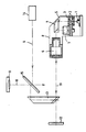
Ein Ausführungsbeispiel der Erfindung ist in der Zeichnung dargestellt und wird im folgenden näher beschrieben. Die einzige Zeichnung zeigt den Strahlengang in der schematisch dargestellten Justiervorrichtung.An embodiment of the invention is shown in the drawing and will be described in more detail below. The only drawing shows the beam path in the adjustment device shown schematically.
In der schematischen Darstellung ist mit (8) ein Gehäuse bezeichnet, in dem eine Lichtquelle (1), ein mehrlinsiger Kondensor (2), ein Filter (3), ein Teilerprisma (4) mit einer Lochblende (5), ein Objektiv (6) und ein Quadrantendetektor (7) ortsfest angeordnet sind. Die im Teilerprisma (4) integrierte Lochblende (5) wird über die Beleuchtungseinheit (1,2,3) ausgeleuchtet. Die Lochblende (5) ist in der Brennebene des Objektivs (6) angeordnet. Das Objektiv (6) entwirft ein Bild der beleuchteten Lochblende im Unendlichen. Von einem fest auf dem in der Zeichnung nicht sichtbaren Waffenrohr aufgesetzten Referenzspiegel (11) wird in einer möglichen Anordnung der Erfindung die Richtung der Mündungstangente der Waffe repräsentiert. Die vom Referenzspiegel (11) über den teildurchlässigen Spiegel (15) und das Umlenkelement (13) reflektierte Strahlung wird durch das Objektiv (6) uber das Teilerprisma (4) auf einen positionsempfindlichen Detektor (7) geleitet. Dieser sensiert Winkelabweichungen des Referenzspiegels und erlaubt somit eine Kompensation einer Dejustierung dürch Verstellung der Zielmarke. Bei einer möglichen Anordnung der Erfindung geht der von einem Zielmarkenprojektor (14) ausgehende Zielmarkenstrahlengang (9) über den teildurchlässigen Spiegel (15) in den Beobachtungsstrahlengang (16). Der Justierstrahlengang (10) wird über Umlenkelemente (13 und 15) auf den Referenzspiegel (11) gelenkt. In einer anderen Anordnung ist ein Spiegel (12) auf der optischen Achse des Objektivs (6) angeordnet. Der Justierstrahl (10) wird direkt auf den Spiegel (12) gelenkt. Eine Zielmarke ist in diesem Fall dem Strahlengang (10) überlagert.In the schematic representation, (8) denotes a housing in which a light source (1), a multi-lens condenser (2), a filter (3), a divider prism (4) with a pinhole (5), an objective (6 ) and a quadrant detector (7) are arranged stationary. The pinhole (5) integrated in the divider prism (4) is illuminated by the lighting unit (1,2,3). The pinhole (5) is arranged in the focal plane of the lens (6). The lens (6) designs an image of the illuminated pinhole in infinity. In a possible arrangement of the invention, the direction of the muzzle tangent of the weapon is represented by a reference mirror (11) which is firmly attached to the weapon barrel (not visible in the drawing). The radiation reflected by the reference mirror (11) via the partially transparent mirror (15) and the deflecting element (13) is passed through the objective (6) via the divider prism (4) to a position-sensitive detector (7). This senses angular deviations of the reference mirror and thus allows compensation for a misalignment by adjusting the target. In a possible arrangement of the invention, the target beam path (9) emanating from a target projector (14) goes via the partially transparent mirror (15) into the observation beam path (16). The adjustment beam path (10) is directed onto the reference mirror (11) via deflection elements (13 and 15). In another arrangement, a mirror (12) is arranged on the optical axis of the objective (6). The adjustment beam (10) is directed directly onto the mirror (12). In this case, a target mark is superimposed on the beam path (10).
Zur Automatisierung der Justierung ist die Einspeisung der ermittelten Korrekturwerte in die Winkelübertragungskette eines Richt-Systems möglich. Die Ablagewerte können auf einem geeigneten Instrument angezeigt und manuell korregiert werden. Es ist ebenfalls möglich, eine Vorrichtung zur Korrektur eines Laserentfernungsmessers zur Visierlinie mit der automatischen Justierung zu kombinieren.To automate the adjustment, the correction values determined can be fed into the angle transmission chain of a straightening system. The storage values can be displayed on a suitable instrument and manually corrected. It is also possible to combine a device for correcting a laser rangefinder to the line of sight with the automatic adjustment.
Claims (6)
Applications Claiming Priority (2)
| Application Number | Priority Date | Filing Date | Title |
|---|---|---|---|
| DE19863622769 DE3622769A1 (en) | 1986-07-07 | 1986-07-07 | DEVICE FOR AUTOMATICALLY ADJUSTING THE SIGHTING LINE OF A TARGET DEVICE FOR DIRECTIONING THE Muzzle Muzzle of a BOARD CANNON OF AN ARMORED VEHICLE |
| DE3622769 | 1986-07-07 |
Publications (2)
| Publication Number | Publication Date |
|---|---|
| EP0254101A2 true EP0254101A2 (en) | 1988-01-27 |
| EP0254101A3 EP0254101A3 (en) | 1990-05-16 |
Family
ID=6304569
Family Applications (1)
| Application Number | Title | Priority Date | Filing Date |
|---|---|---|---|
| EP87109571A Withdrawn EP0254101A3 (en) | 1986-07-07 | 1987-07-03 | Automatic adjustment device for the line of sight of a sighting mechanism in relation to the direction of the muzzle tangent of the board gun of an armoured vehicle |
Country Status (2)
| Country | Link |
|---|---|
| EP (1) | EP0254101A3 (en) |
| DE (1) | DE3622769A1 (en) |
Cited By (1)
| Publication number | Priority date | Publication date | Assignee | Title |
|---|---|---|---|---|
| FR2643157A1 (en) * | 1989-02-16 | 1990-08-17 | Leitz Wild Gmbh | AUTOMATIC ADJUSTING DEVICE FOR A VISEE APPARATUS |
Families Citing this family (1)
| Publication number | Priority date | Publication date | Assignee | Title |
|---|---|---|---|---|
| DE3942922A1 (en) * | 1989-12-23 | 1991-06-27 | Rheinmetall Gmbh | Optical measurer or angles between parallel optical axes - contg. pivotable arm carrying beam splitter and is self-adjusting for use with auto-collimation camera |
Citations (4)
| Publication number | Priority date | Publication date | Assignee | Title |
|---|---|---|---|---|
| DE2725819A1 (en) * | 1977-06-08 | 1978-12-14 | Bodenseewerk Geraetetech | Steering or tracking system for guided missiles - has semi-transparent mirror and two dimensional light transmitter for generating target mark |
| DE2926972A1 (en) * | 1979-07-04 | 1981-01-22 | Wegmann & Co | DEVICE FOR STABILIZING THE SIGHT LINE OF AN OPTICAL VISOR FOR A WEAPON |
| DE2618976B2 (en) * | 1975-10-01 | 1981-06-04 | L'Etat Français représenté par le Délégué Général pour l'Armement, Paris | Optical target observation device |
| DE3047958A1 (en) * | 1980-12-19 | 1982-07-01 | Siemens AG, 1000 Berlin und 8000 München | ALIGNMENT AND OBSERVATION DEVICE FOR WEAPON SYSTEMS |
-
1986
- 1986-07-07 DE DE19863622769 patent/DE3622769A1/en not_active Withdrawn
-
1987
- 1987-07-03 EP EP87109571A patent/EP0254101A3/en not_active Withdrawn
Patent Citations (4)
| Publication number | Priority date | Publication date | Assignee | Title |
|---|---|---|---|---|
| DE2618976B2 (en) * | 1975-10-01 | 1981-06-04 | L'Etat Français représenté par le Délégué Général pour l'Armement, Paris | Optical target observation device |
| DE2725819A1 (en) * | 1977-06-08 | 1978-12-14 | Bodenseewerk Geraetetech | Steering or tracking system for guided missiles - has semi-transparent mirror and two dimensional light transmitter for generating target mark |
| DE2926972A1 (en) * | 1979-07-04 | 1981-01-22 | Wegmann & Co | DEVICE FOR STABILIZING THE SIGHT LINE OF AN OPTICAL VISOR FOR A WEAPON |
| DE3047958A1 (en) * | 1980-12-19 | 1982-07-01 | Siemens AG, 1000 Berlin und 8000 München | ALIGNMENT AND OBSERVATION DEVICE FOR WEAPON SYSTEMS |
Cited By (5)
| Publication number | Priority date | Publication date | Assignee | Title |
|---|---|---|---|---|
| FR2643157A1 (en) * | 1989-02-16 | 1990-08-17 | Leitz Wild Gmbh | AUTOMATIC ADJUSTING DEVICE FOR A VISEE APPARATUS |
| DE3904705A1 (en) * | 1989-02-16 | 1990-08-23 | Leitz Wild Gmbh | AUTOMATIC ADJUSTMENT FOR A VISOR DEVICE |
| GB2229598A (en) * | 1989-02-16 | 1990-09-26 | Leitz Wild Gmbh | Viewfinder adjustment in sighting means |
| US4975565A (en) * | 1989-02-16 | 1990-12-04 | Wild Leitz Gmbh | Automatic adjusting device for a sighting system |
| GB2229598B (en) * | 1989-02-16 | 1993-04-07 | Leitz Wild Gmbh | Viewfinder adjustment in sighting means |
Also Published As
| Publication number | Publication date |
|---|---|
| DE3622769A1 (en) | 1988-01-21 |
| EP0254101A3 (en) | 1990-05-16 |
Similar Documents
| Publication | Publication Date | Title |
|---|---|---|
| DE2710904C2 (en) | ||
| DE2654151C2 (en) | Day and night aiming device for guiding missiles | |
| DE2414382C2 (en) | Optical collimating alignment arrangement | |
| DE3341232A1 (en) | FIRE CONTROL SYSTEM | |
| DE2625081B2 (en) | Device for the automatic harmonization of several devices | |
| EP2047317B1 (en) | Telescopic sight | |
| EP0254101A2 (en) | Automatic adjustment device for the line of sight of a sighting mechanism in relation to the direction of the muzzle tangent of the board gun of an armoured vehicle | |
| DE3904705C2 (en) | Automatic adjustment device for a sighting device | |
| DE102008015423A1 (en) | Visor with objective viewpoint e.g. for weapons with ammunition for flight paths, involves having sight line straightening at target against running axis by vertical or horizontal tilting | |
| EP2894507B1 (en) | Telescope with prism inversion system | |
| EP0179387A2 (en) | Device for carrying out dynamic comparative measurements in a fire control system for a directed weapon | |
| EP0347525B1 (en) | Optical aiming device, especially a main sighting telescope for an armoured tank | |
| EP0095577A2 (en) | Process and device for checking the synchronism of an optical sighting device, and a device to be directed onto a target, particularly a weapon | |
| DE2054387B2 (en) | COMBINED VISION DEVICE TRAINED AS DAY-NIGHT TARGET DEVICE | |
| DE2926973C2 (en) | ||
| EP1992911A2 (en) | Laser distance measuring module and system composed of optical telescope system from laser distance measuring module | |
| DE2704185A1 (en) | DAY / NIGHT VISION DEVICE | |
| DE3623455C2 (en) | ||
| DE921717C (en) | Optical testing devices for centering, coaxial adjustments and alignments | |
| DE2054387C (en) | Combined sighting device designed as a day and night target device | |
| DE1190361B (en) | Detachable aiming device attached to a firearm | |
| DE216896C (en) | ||
| DE2362863C3 (en) | ||
| DE3234289A1 (en) | Aiming device for a portable firearm | |
| DE2926972A1 (en) | DEVICE FOR STABILIZING THE SIGHT LINE OF AN OPTICAL VISOR FOR A WEAPON |
Legal Events
| Date | Code | Title | Description |
|---|---|---|---|
| PUAI | Public reference made under article 153(3) epc to a published international application that has entered the european phase |
Free format text: ORIGINAL CODE: 0009012 |
|
| AK | Designated contracting states |
Kind code of ref document: A2 Designated state(s): CH DE FR GB IT LI NL |
|
| PUAL | Search report despatched |
Free format text: ORIGINAL CODE: 0009013 |
|
| AK | Designated contracting states |
Kind code of ref document: A3 Designated state(s): CH DE FR GB IT LI NL |
|
| 17P | Request for examination filed |
Effective date: 19901020 |
|
| STAA | Information on the status of an ep patent application or granted ep patent |
Free format text: STATUS: THE APPLICATION IS DEEMED TO BE WITHDRAWN |
|
| 18D | Application deemed to be withdrawn |
Effective date: 19920201 |
|
| RIN1 | Information on inventor provided before grant (corrected) |
Inventor name: TIETZ, TRAUGOTT Inventor name: POXLEITNER, MARTIN Inventor name: WEINHEIMER, HANS-RICHARD, DR. Inventor name: STANA, HANS |