EP0259044A2 - Method and apparatus for systematically testing objects including tennis balls - Google Patents
Method and apparatus for systematically testing objects including tennis balls Download PDFInfo
- Publication number
- EP0259044A2 EP0259044A2 EP87307233A EP87307233A EP0259044A2 EP 0259044 A2 EP0259044 A2 EP 0259044A2 EP 87307233 A EP87307233 A EP 87307233A EP 87307233 A EP87307233 A EP 87307233A EP 0259044 A2 EP0259044 A2 EP 0259044A2
- Authority
- EP
- European Patent Office
- Prior art keywords
- station
- ball
- operating
- transporting
- computer
- Prior art date
- Legal status (The legal status is an assumption and is not a legal conclusion. Google has not performed a legal analysis and makes no representation as to the accuracy of the status listed.)
- Withdrawn
Links
Images


Classifications
-
- G—PHYSICS
- G01—MEASURING; TESTING
- G01D—MEASURING NOT SPECIALLY ADAPTED FOR A SPECIFIC VARIABLE; ARRANGEMENTS FOR MEASURING TWO OR MORE VARIABLES NOT COVERED IN A SINGLE OTHER SUBCLASS; TARIFF METERING APPARATUS; MEASURING OR TESTING NOT OTHERWISE PROVIDED FOR
- G01D21/00—Measuring or testing not otherwise provided for
- G01D21/02—Measuring two or more variables by means not covered by a single other subclass
-
- G—PHYSICS
- G01—MEASURING; TESTING
- G01N—INVESTIGATING OR ANALYSING MATERIALS BY DETERMINING THEIR CHEMICAL OR PHYSICAL PROPERTIES
- G01N35/00—Automatic analysis not limited to methods or materials provided for in any single one of groups G01N1/00 - G01N33/00; Handling materials therefor
-
- G—PHYSICS
- G01—MEASURING; TESTING
- G01N—INVESTIGATING OR ANALYSING MATERIALS BY DETERMINING THEIR CHEMICAL OR PHYSICAL PROPERTIES
- G01N3/00—Investigating strength properties of solid materials by application of mechanical stress
-
- G—PHYSICS
- G01—MEASURING; TESTING
- G01N—INVESTIGATING OR ANALYSING MATERIALS BY DETERMINING THEIR CHEMICAL OR PHYSICAL PROPERTIES
- G01N33/00—Investigating or analysing materials by specific methods not covered by groups G01N1/00 - G01N31/00
- G01N2033/0078—Investigating or analysing materials by specific methods not covered by groups G01N1/00 - G01N31/00 testing material properties on manufactured objects
- G01N2033/008—Investigating or analysing materials by specific methods not covered by groups G01N1/00 - G01N31/00 testing material properties on manufactured objects sport articles (balls, skis, rackets)
-
- G—PHYSICS
- G01—MEASURING; TESTING
- G01N—INVESTIGATING OR ANALYSING MATERIALS BY DETERMINING THEIR CHEMICAL OR PHYSICAL PROPERTIES
- G01N2203/00—Investigating strength properties of solid materials by application of mechanical stress
- G01N2203/0058—Kind of property studied
- G01N2203/0076—Hardness, compressibility or resistance to crushing
- G01N2203/0085—Compressibility
Definitions
- Tennis balls and other objects have heretofore been measured, tested, and otherwise treated to determine if they meet standards or specifications (see U.S. Patent No. 4,472,960).
- tennis balls have been tested using test stations in which operation of the stations is by hand and transport of the balls from station-to-station is manually accomplished. Testing is formed to meet ball requirements of international, national and other tennis organizations.
- Prior ball testing equipment has included calipers, "go no-go" gauges for measuring diameters, and scales for determining weight.
- Other ball test equipment has included compression vices for compressing the ball under known loads to measure ball deflection.
- the present invention is a computer-controlled array of conditioning, test and measuring stations for conditioning objects and thereafter testing and measuring the objects in a controlled, timed, and selected sequence.
- a central computer initiates, controls and terminates each test step at each substation in each test station.
- the computer also controls the electromechanical devices which transport and handle the objects and finally the computer processes test information and inputs such information in processed form to a display terminal and to a printer to record selected measurements and other test results.
- a plurality of deformable objects such as tennis balls may concurrently be conditioned, tested and measured while test data is recorded, processed and stored.
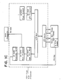
- Fig. 1A the components of the system steps to be followed to practice of the invention are shown in diagram form.
- the system is prepared for start up including entering data identifying the plurality of balls to be tested by customer name, by individual ball, and so forth. Balls are fed seriatim to the first station for preconditioning. The video display is used to assure proper sequence and operation of the system. Upon completion of the bounce test, the balls are again fed in proper order to the final station for the deformation tests. Finally, tests may be printed for reporting to the customer.
- the system test equipment (Test Equip.) is operated and controlled by a central computer unit (CPU).
- the computer processor preferably has 68000/8MHZ/32 bit registers and a memory of 384KB RAM/25ONS access time and up to 128KB ROM.
- An IBM 9001 Instrument Computer has been found satisfactory.
- Other components include real time control system (RTC); operating system (O/S) and software system (S/W). Also shown are video display console (CRT) and input keyboard (KB).
- Computer programs useful in operating the computer used in the system as written in assembly language are annexed hereto as Appendices 1-4.
- Appendices 1 (52 pp) and 2 (139 pp) contain the code necessary to implement the data processing performed by the front end processor while Appendix 3 (52 pp) contains the code associated with I/O functions performed by the front end processor.
- Appendix 4 contains the code necessary to implement the I/O functions performed by the user controlled host computer.
- Fig. 1C represents the as built system configuration.
- Tennis balls used in tournaments or other official plays must meet specified standards.
- the United States Tennis Association has promulgated the following standards for tennis balls: "...The ball shall be more than two and a half inches (6.35 cm.) and less than two and five-eights inches (6.67cm).) in diameter, and more than two ounces (56.7 grams) and less than two and one-sixteenth ounces (58.5 grams) in weight.
- the ball shall have a bound of more than 53 inches (135cm.) and less than 58 inches (147cm). when dropped 100 inches (254cm.) upon a concrete base.
- the ball shall have a forward deformation of more than .220 of an inch (.56cm) and less than .290 of an inch (.74cm.) and a return deformation of more than .350 of an inch (.89cm.) and less than .425 of an inch (1.08cm.) at 18 lb. (8.165kg.) load.
- the two deformation figures shall be the averages of three individual readings along three axes of the ball and no two individual readings shall differ by more than .030 of an inch (.08cm.) in each case.”
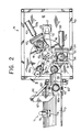
- the preconditioning station 9 functions to flex tennis balls prior to sizing, weighing and other testing.
- Station 9 includes frame structure 10, base 11, floor 12, and top 13.
- Mounted on station floor 12 is tennis ball turntable 16 having four (4) keyhole-shaped ball support wells 15x, 15y, 15z and 15e.
- Turntable 16 is rotated in a counterclockwise indexing manner by stepping drive motor 17, motor drive shaft 18, shaft pulley 19, table pulley-shaft unit 20 and belt 21.
- Ball jacks 22, 23 serving substations x and y include dished ball cradles 24 mounted on reciprocating pistons 26 driven upwardly by air pressure and returned by gravity. Ball cradles 24 are shaped and sized to fit through keyhole support wells 15x and 15y.
- Ball 1 (the first ball in a series of balls to be tested) is positioned at substation x and the precompression process is started up through operation of the computer control equipment, jack 22 lifts the Ball 1 up to the position shown in dashed lines 28 (Fig. 1). While in this position Ball 1 is compressed by horizontal ball compressor unit 29x which includes stationary jaw plate 31, a pair of spaced-apart guide rod-sleeves 32, 33, movable jaw plate 34, and pneumatic cylinder 30. Movable jaw plate 34 is driven toward stationary plate 31 causing compression of Ball 1 until it engages sleeves 36, 37 of guide-rod sleeves 32, 33 respectively.
- Sleeves 36, 37 serve to limit the amount of ball compression.
- Movable jaw plate 34 is retracted; jack 22 lowered, and Ball 1 returned to well 15x.
- Turntable 16 then rotates counterclockwise (Fig. 2) until Ball 1 reaches substation 15y where jack 23 elevates Ball 1 for compression by ball compressor unit 39y.
- Compressor 39y like compressor 29x, has fixed jaw 41, movable jaw 42 and pneumatic drive cylinder 43 (Fig. 2). Compression of Ball 1 at substation y is accomplished along an axis of the ball different from the axis of compression at substation x.
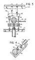
- Ball 1 Upon the subsequent counterclockwise movement (indexing) of turntable 16 to substation z, Ball 1 is further compressed by compressor unit 46z mounted on base 10 and top 13 for vertical movement. Movable horizontal jaw 49 is moved toward fixed jaw 48 by cylinder 51. Movable jaw guides 52, 53 and stop sleeves 54, 56 are shown. Guide 56 is interrupted to avoid interference with turntable 16 (Fig. 3).
- Size gauge station 61 includes three (3) superimposed circular openings (oversize upper opening 62, undersize middle opening 63, and small ball rest opening 64) formed by superimposed half portions 62a, 62b, 63a, 63b and 64a, 64b in a frame box section 60, one section 60a stationary and one section 60b pivotal to expand the circular openings to release the ball upon completion of the gauging of its size.
- Ball 1 reaches uppermost opening 62 as it is discharged from precompression exit shute 59. If Ball 1 is oversized, it will not pass through uppermost circular opening 62. If Ball 1 has a diameter within the desired range, it will not pass openings 63 and come to rest there (see Fig. 1). If the Ball is too small, it will pass both upper and middle openings 62, 63 and come to rest on lower opening 64.
- size gauge box 60 is opened a small distance by operation of pneumatic piston arrangement 66 including pivot arm 67 for pivotally moving box section 60a about axis 68 causing Ball 1 to drop onto inclined size-measuring trough 70.
- Ball 1 rolls down trough 70 until it engages side mounted measuring unit 71 which includes measuring head 72 (Fig. 4).
- Head 72 is mounted on reciprocal piston 73 supported in bearings 74, 76 and normally urged by gravity and a spring (not shown) downwardly until ring stop 77 engages bearing mount 74.
- the highest position of the piston 73 is measured by a sensor (not shown) as Ball 1 passes. This measurement is used by the computer to determine the diameter of Ball 1.
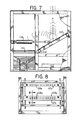
- FIG. 5 Ball 1 exits trough 70 onto weigh scale 77.
- Scale 77 includes ball seat 78 connected to movable scale plate 79 which moves downwardly in response to the weight of Ball 1. Any commercial weigh scale capable of weighing a tennis ball may be used.
- Ball 1 is readied for a bounce test as it is seized by air-operated gripper unit 81 which has two fingers 82, 83 pivotal about pins 82a, 83a respectively.
- Pins 82a, 83a are mounted on cylinder and lifting frame 84.
- Lifting frame 84 includes metallic sleeve 86 mounted on vertical tube track 87.
- Cylindrical ball lifting frame 84 is caused to move up and down along tube track 87 by the movement of a cylinder magnet 91 slidably positioned inside the tube track 87 which magnet 91 emits sufficient magnetic forces to cause metallic sleeve 86 (together with its lifting frame 84) to follow magnet 91 up and down tube track 87. Movement of magnet 91 is accomplished by air pressure in the tube track 87 supplied through air hose 92. Also shown is bounce test station frame 93.
- Ball 1 is elevated ball catcher pan 94 moves, as directed by the central computer, from the position shown in Fig. 5 to the left by cylinder-piston unit 95 to permit lifter frame 84 to pass.
- catcher pan 94 moves right to the position of Fig. 5 to catch Ball 1 as released by the gripper unit 81.
- Ball 1 then rolls down pan ramp 96 onto inclined pan mount piece 97 and finally to horizontal pan rest section 98 where second gripper unit 100 engages and holds Ball 1.
- Second gripper unit 100 has the same construction and operation as gripper unit 81.
- Ball 1 is ready for the bounce test upon the subsequent indexing of the system at which time, pan 94 is moved right to place pan drop hole 101 under Ball 1. Second gripper unit 100 then releases Ball 1 which starts its descent.
- Ball 1 falls a selected distance until it strikes stationary bounce plate 102 and rebounds upwardly (See Fig. 7). Prior to Ball 1 reaching the deflection door area during its descent, door 103 is provided about axis 104 to its open position by air cylinder unit 106. As Ball 1 rebounds upwardly it passes through one or more infra red detector beam arrays 107a, b, and c providing data as to both height of rebound and angle of rebound of Ball 1. Each array has a plurality of infra red beam units 108 with each unit having a transmitter 108a and a receiver 108b (not shown) spaced apart a sufficient distance to permit passage of the descending and rebounding balls. The breaking of the infra beam of one or more beam units 108 indicates the presence of Ball 1.
- Lowest array 107a is placed at the minimum height to which the ball is required to bounce to meet the desired standards. If the Ball 1 does not pass through one or more beam units 108 or lower array 107a, the minimum bounce has not been attained. Middle array 107b is positioned close to the lower array 107a and upper array 107c is positioned at the maximum bounce level.
- array unit 107b may be turned ninety (90TM) degrees so that its beam transmissions are perpendicular to the beam transmission of its unit 107a.
- deflector door 103 is closed to deflect Ball 1 into collection hopper 110.
- Ball 1 is manually removed from the collection hopper 110 and thereafter manually placed in the compression station as hereinafter described.
- the preconditioning routine (in which Ball 1 is compressed three times in each substation x, y and z) is followed for a total of nine (9) compressions. It will be seen that Ball 1 is subjected to eighteen (18) separate operations including conditioning, measuring, testing and transporting (see the chart of Fig. 12). Ball 2 is manually placed at substation x following the first indexing of the system after Ball 1 has been compressed at substation x and advanced to substation y. Subsequent balls 3, 4, 5, etc. are similarly manually placed at substation x. All balls follow the same operation in the same sequence as Ball 1 with all balls arriving in collection hopper 110.
- Ball 1 (and other balls) is removed from collection hopper 110 and placed in ball compression unit 112 for testing.
- Compression unit 112 includes turntable 113 driven by motor 114 through belt 116 and pulleys 117, 118. Ball 1 is placed in substation x ⁇ for deformation.
- Movable platen 119 of deformer unit 112 translate on guide rods 121, 122 mounted in fixed platen 123.
- Sleeves 124, 126 function as stops limiting travel of the movable platen 119 by air drive unit 127.
- Movable platen 119 is urged away from Ball 1 by counterweight unit 129 comprising weight 131, wire 132, and pulley 133.
- Counterweight unit 129 places a predetermined pull on movable platen 119 with air piston unit 120 urging platen 119 in the opposite direction.
- the air cylinder unit 120 applies an initial contact force of 3.5 lbs. against Ball 1.
- a zero displacement reading is stored in the computer's memory.
- the force on Ball 1 is increased to 21.5 lbs. (See Fig. 11A).
- the forward deformation of the Ball 1 (.243 inches: Fig. 11A) is measured by displacement transducer 135x ⁇ , which measurement is stored in the computer's memory, and displayed on the CRT (Fig. 1B).
- Time T2 milliseconds after T1 + 5
- pressure is applied deforming Ball 1 to 1 inch.
- the pressure is relieved, and the force on Ball 1 restored to 21.5 lbs. (3.4 + 18) at time T3.
- the reverse deformation reading is stored in memory, displayed on the front panel, and a green indicator lamp (not shown) turns on if Ball 1 passes both deformation specification, (or a red lamp) if Ball 1 fails.
- Ball 2 is subjected to a similar test sequence with differing deflection results (Fig. 11B).
- Ball compression unit 141 includes the same components as ball compression unit 120 including pneumatic drive assembly 142, fixed and movable ball platens 143, 144; platen guides 146, 147 and sleeves 148, 150.
- Transducer 135y includes cylinder 160, cylinder piston 161 and left and right magnetized piston feet 162, 163.
- Metal frame mounted stop 164 and metal movable platen 144 engage and disengage feet 162, 163 to limit the travel of piston 161.
- Ball 162 When piston 161 is moved in the arrow A direction foot 162 remains engaged to move platen 144 through the force of magnetism. When piston 161 moves in the arrow B direction, foot 162 engages stop 164 where it is held through the force of magnetism until platen 144 returns to pick up and move piston 161 in a return stroke.
- This arrangement permits the travel of transducer piston 161 to be limited to increase accuracy of its measurements.
- Ball 1 is then carried by turntable 113 to substation z ⁇ for compression along a different axis.
- Ball compression unit 151 is constructed similarly to units 120, 142. Compression unit 151 is mounted with compression platens positioned for operation toward and away from each other in a vertical plane. Displacement transducer 135y ⁇ measures the location of the movable platen which location is fed to the computer.
- preconditioning subsystems PC-V1 through PC-V6 are powered from power supplies PS-1-5 (see Fig. 13A) through relay interface board (IBI).
- Preconditioning subsystems PC-V1 through PC-V6 include operation of three (3) preconditioning substations x, y, and z, discharge station e, go-no-go size gauge and diameter size gauge.
- Stepping motor controller (SMC1) controls stepping motor (SM1) which causes precondition station turntable 16 to index by turning a selected number of degrees and then stopping for a preset time before commencing the next indexing operation.
- Cylinder position switches (CP1) actuate jacks 22, 23 to raise each ball at substations x and y for preconditioning and thereafter lower each ball for further turntable transport.
- Optical ball-in-place (BIP) units indicated when the ball is properly located.
- pick and place units (ball gripper units (PP-V1 through PPV-5) are powered through relay interface board (IB2).
- Unites (PPV1 through PPV-5) operate solenoid valves of gripper ball units which lift, hold, and drop the balls. Solenoid valves also operate the ball pan collector and the ball deflector door.
- relay interface board (IB3) which distributes power to keyboard, scale and communicates cable (RS232).
- ITS2 input terminal strip which is connected to cylinder control switch (CP1) and ball-in-place switch (BIP).
- relay interface board (IB4) serves subsystems (DF-V1 through DF-V6) with stepping motors (SM2,3) controlled by stepping motor controller (SMC2,3) respectively. Also shown are low friction linear sensors (LFLS2-4) and pressure transducer (PT1).
- LFLS2-4 low friction linear sensors
- PT1 pressure transducer
- Fig. 13A shows connector panels, the preconditioning subsystem (PC), pick-and-place subsystem (PC) and deformation subsystem (DF). Power supplier units are also shown (PS1, 2, 3.1, 3.2, 3.3, 4 and 5).
- an infra red detector beam array comprising optical array LED board 200 which produces 14 essentially parallel light beams and optical array detector and encoder board 210 which detects the presence of said light beams.
- Optical array LED board 200 comprises light emitting diodes (LED) LED1 and through LED14, which are arranged in a linear fashion. Associated with each LED is a series resistor to ground (R1-R14) serving to limit current through the LEDs. Resistors R1 through R14 illustratively are 18 ohm, 1 watt resistors while LEDs LED1 through LED14 illustratively are infrared emitting diodes of the type G.E. F5D1.
- Optical array detector and encoder board 210 comprises light detectors LD1 through LD14 arranged in a linear fashion such that each light detector may detect any interruption of the light beam produced by its LED counterpart on optical array LED board 200.
- LD1 through LD7 comprise the seven right side light detectors while LD8 through LD14 comprise the seven left side light detectors.
- LD1 through LD7 are input to U1, a 74LS00 quad 2 Input NAND Gate chip while LD8 through LD14 are input to U2, a 74LS11 Tri 3 Input AND Gate chip.
- U1 and U2 produce a 3 bit address on lines B0 ⁇ , 1 and B2 indicating which infra red beams have been interrupted. This 3 bit address indicates which beams from the center of the array have been interrupted. To determine whether the interrupted beam is on the right or left side, lines EOH (right side) and EOL (left side) are used.
- each of the optical arrays one which is depicted in Fig. 14A, is enabled and disabled under computer control. Enabling of an array exists during a window or slice in time.
- Clock generator U12 of Fig. 14C generates a 4MHz clock signal which is input to 8 bit shift register U9 of Fig. 14B.
- U9 illustratively a 74199 device, is computer controlled and produces enabling signals on lines CLK0 ⁇ , CLK1 and CLK2 functioning as three windows for the three LED arrays.
- CLK0 ⁇ CLK1 and CLK2 are input to U7B, U6B and U6A of Fig. 14C respectively.
- U6 and U7 are 74120 type Dual Pulse Synchronizers/Drivers. Signals EOL and EOH which are used to determine whether an interruption exists on the left or right side of an array are input to U6 and U7.
- signals EOL2, EOH2 which indicate whether an interruption exists for the left or right side of the uppermost array are input to NOR gate U5-A.
- signals EOL1, EOH1 corresponding to the center array are input to NOR gate U5-C and signals EOL0 ⁇ , EOH0 ⁇ corresponding to the lowest array are input to NOR gate U5-D.
- Nor gates U5-A, U5-D and U5-C are input to drivers U6-A, U6-B and U7-B respectively.
- the output of these three drivers are input to U11, a 74116 type Dual Quad Latch.
- the three output lines of U11B are input to a front end processor FEP and indicate which of the three arrays is presently being interrupted.
- U11A The three bit address on lines B0 ⁇ , B1, and B2 from each array indicating which beams have been interrupted are input to U11A.
- the output of U11A is input to the FEP over lines LB0 ⁇ -LB2 and thus represents which beams have been interrupted.
- the output of AND gate U2-C is input to U11A and indicates whether the interruption exists on the right or the left half of an array. U11A outputs this signal to the FEP on line LB3.
- Flip Flop U3-A outputs a pulse on line T0 ⁇ 1 which synchronizes the resetting of the arrays.
- Mutivibrator U8-B of Fig. 14C serves to hold the date of U11-B for a predetermined amount of time before sending such data to the FED.
- optocoupler OC1 serves to isolate input noise from the system as well as to provide power to the optical arrays.
- Signal EOA is input to OC1 which outputs its complement.
- Inverter U4-A inverts this signal to provide inverters U4-D, U4-E, U4-F with the EOA signal.
- the output of these three inverters are input to solid state relays SSR0 ⁇ , SSR1, SSR2 respectively.
- Voltage regulators VR0 ⁇ , VR1 and VR2 are each individually adjusted by a potentiometer, thus providing a precise voltage output to relays SSR0 ⁇ , SSR1, SSR2 respectively. The outputs of these three relays are then used to power the optical arrays.
Abstract
Description
- Tennis balls and other objects have heretofore been measured, tested, and otherwise treated to determine if they meet standards or specifications (see U.S. Patent No. 4,472,960). In particular, tennis balls have been tested using test stations in which operation of the stations is by hand and transport of the balls from station-to-station is manually accomplished. Testing is formed to meet ball requirements of international, national and other tennis organizations.
- Prior ball testing equipment has included calipers, "go no-go" gauges for measuring diameters, and scales for determining weight. Other ball test equipment has included compression vices for compressing the ball under known loads to measure ball deflection.
- While other semiautomated systems for transport and inspection have been proposed for meat packages (U.S. Patent No. 3,515,053) and biscuits (U.S. Patent No. 3,435,685) no satisfactory system or method for testing objects, such as tennis balls, has been known or available.
- Broadly, the present invention is a computer-controlled array of conditioning, test and measuring stations for conditioning objects and thereafter testing and measuring the objects in a controlled, timed, and selected sequence. A central computer initiates, controls and terminates each test step at each substation in each test station. The computer also controls the electromechanical devices which transport and handle the objects and finally the computer processes test information and inputs such information in processed form to a display terminal and to a printer to record selected measurements and other test results.
- It is a feature that a plurality of deformable objects such as tennis balls may concurrently be conditioned, tested and measured while test data is recorded, processed and stored.
-
- Fig. 1A is a flow sheet showing the overall method;
- Fig. 1B is a block diagram relating to the method of the invention;
- Fig. 1C is a further block diagram relating to the host computer and associated equipment;
- Fig. 1 is an elevational view of the preconditioning and sizing stations;
- Fig. 2 is a sectional view taken along line 2-2- of Fig. 1;
- Fig. 3 is a sectional view taken along line 3-3 of Fig. 2;
- Fig. 4 is a sectional view taken along line 4-4 of Fig. 1;
- Fig. 5 is a front elevational view of the bounce test station;
- Fig. 6 is a sectional view taken along line 6-6 of Fig. 5;
- Fig. 7 is an enlarged partial front elevational view of the bounce test station;
- Fig. 8 is a sectional view taken along line 8-8 of Fig. 5;
- Fig. 9 is a sectional end view showing the ball detectors;
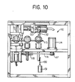
- Fig. 10 is a front elevational view of the compression station;
- Fig. 11 is a plan view of the compression station;
- Figs. 11A and 11B depict, in graphical form, forward and reverse ball deflection curves;
- Fig. 12 depicts a testing chart for a ten-ball, thirty-cycle test;
- Figs. 13A-13D show the wiring diagrams; and
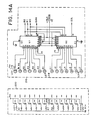
- Figs. 14A-14C show logic control circuitry related to the bounce test station operation.
- With respect to Fig. 1A the components of the system steps to be followed to practice of the invention are shown in diagram form. The system is prepared for start up including entering data identifying the plurality of balls to be tested by customer name, by individual ball, and so forth. Balls are fed seriatim to the first station for preconditioning. The video display is used to assure proper sequence and operation of the system. Upon completion of the bounce test, the balls are again fed in proper order to the final station for the deformation tests. Finally, tests may be printed for reporting to the customer.
- Referring to Fig. 1B, the system test equipment (Test Equip.) is operated and controlled by a central computer unit (CPU). The computer processor preferably has 68000/8MHZ/32 bit registers and a memory of 384KB RAM/25ONS access time and up to 128KB ROM. An IBM 9001 Instrument Computer has been found satisfactory. Other components include real time control system (RTC); operating system (O/S) and software system (S/W). Also shown are video display console (CRT) and input keyboard (KB). Computer programs useful in operating the computer used in the system as written in assembly language are annexed hereto as Appendices 1-4. More specifically, Appendices 1 (52 pp) and 2 (139 pp) contain the code necessary to implement the data processing performed by the front end processor while Appendix 3 (52 pp) contains the code associated with I/O functions performed by the front end processor. In addition,
Appendix 4 contains the code necessary to implement the I/O functions performed by the user controlled host computer. Fig. 1C represents the as built system configuration. - Tennis balls used in tournaments or other official plays must meet specified standards. For example, the United States Tennis Association has promulgated the following standards for tennis balls:
"...The ball shall be more than two and a half inches (6.35 cm.) and less than two and five-eights inches (6.67cm).) in diameter, and more than two ounces (56.7 grams) and less than two and one-sixteenth ounces (58.5 grams) in weight.
The ball shall have a bound of more than 53 inches (135cm.) and less than 58 inches (147cm). when dropped 100 inches (254cm.) upon a concrete base.
The ball shall have a forward deformation of more than .220 of an inch (.56cm) and less than .290 of an inch (.74cm.) and a return deformation of more than .350 of an inch (.89cm.) and less than .425 of an inch (1.08cm.) at 18 lb. (8.165kg.) load. The two deformation figures shall be the averages of three individual readings along three axes of the ball and no two individual readings shall differ by more than .030 of an inch (.08cm.) in each case." - Regulations are also specified by the Association as to the temperature, humidity and other conditions under which tests are to be performed including initial flexing of the ball before testing (precompression steps).
- With respect to Fig. 1, 2, and 3, the
preconditioning station 9 functions to flex tennis balls prior to sizing, weighing and other testing.Station 9 includesframe structure 10,base 11,floor 12, and top 13. Mounted onstation floor 12 istennis ball turntable 16 having four (4) keyhole-shapedball support wells Turntable 16 is rotated in a counterclockwise indexing manner by steppingdrive motor 17,motor drive shaft 18,shaft pulley 19, table pulley-shaft unit 20 andbelt 21. There are four (4) substation positions instation 9 marked x, y, z and e (Fig. 2). - The tennis ball at positions x, and y are raised and lowered by pneumatic cylinder ball jacks 22, 23 positioned below balls positioned at positions x, y, and z. Ball jacks 22, 23 serving substations x and y (substation z does not require a jack since the ball is compressed in place) include dished ball cradles 24 mounted on
reciprocating pistons 26 driven upwardly by air pressure and returned by gravity. Ball cradles 24 are shaped and sized to fit throughkeyhole support wells 15x and 15y. - Each tennis ball to be tested is placed manually at substation x oriented to avoid compression of a seam. Ball 1 (the first ball in a series of balls to be tested) is positioned at substation x and the precompression process is started up through operation of the computer control equipment, jack 22 lifts the
Ball 1 up to the position shown in dashed lines 28 (Fig. 1). While in thisposition Ball 1 is compressed by horizontalball compressor unit 29x which includesstationary jaw plate 31, a pair of spaced-apart guide rod-sleeves 32, 33,movable jaw plate 34, andpneumatic cylinder 30.Movable jaw plate 34 is driven towardstationary plate 31 causing compression ofBall 1 until it engagessleeves rod sleeves 32, 33 respectively.Sleeves Movable jaw plate 34 is retracted;jack 22 lowered, andBall 1 returned towell 15x.Turntable 16 then rotates counterclockwise (Fig. 2) untilBall 1 reaches substation 15y wherejack 23 elevatesBall 1 for compression byball compressor unit 39y.Compressor 39y, likecompressor 29x, has fixedjaw 41,movable jaw 42 and pneumatic drive cylinder 43 (Fig. 2). Compression ofBall 1 at substation y is accomplished along an axis of the ball different from the axis of compression at substation x. - Upon the subsequent counterclockwise movement (indexing) of
turntable 16 to substation z,Ball 1 is further compressed bycompressor unit 46z mounted onbase 10 and top 13 for vertical movement. Movablehorizontal jaw 49 is moved toward fixedjaw 48 bycylinder 51. Movable jaw guides 52, 53 and stopsleeves Guide 56 is interrupted to avoid interference with turntable 16 (Fig. 3). - Subsequent indexing of
turntable 16 may moveBall 1 through one or more cycles of substations x, y and z for further treatment orBall 1 may be directed to exitposition 15e wheredischarge jack 57 includinginclined head 58 is raised to causeBall 1 to roll intoexit shute 59 for delivery to the size gauge station 61 (see Figs. 1 and 2).Size gauge station 61 includes three (3) superimposed circular openings (oversizeupper opening 62, undersizemiddle opening 63, and small ball rest opening 64) formed by superimposedhalf portions frame box section 60, onesection 60a stationary and one section 60b pivotal to expand the circular openings to release the ball upon completion of the gauging of its size. -
Ball 1 reachesuppermost opening 62 as it is discharged fromprecompression exit shute 59. IfBall 1 is oversized, it will not pass through uppermostcircular opening 62. IfBall 1 has a diameter within the desired range, it will not passopenings 63 and come to rest there (see Fig. 1). If the Ball is too small, it will pass both upper andmiddle openings - Upon the next indexing of the test system,
size gauge box 60 is opened a small distance by operation ofpneumatic piston arrangement 66 includingpivot arm 67 for pivotally movingbox section 60a aboutaxis 68 causingBall 1 to drop onto inclined size-measuringtrough 70.Ball 1 rolls downtrough 70 until it engages side mounted measuringunit 71 which includes measuring head 72 (Fig. 4).Head 72 is mounted onreciprocal piston 73 supported inbearings ring stop 77 engages bearingmount 74. When rollingBall 1 engagesangular head 72, it forceshead 72 upwardly to allow theBall 1 to clearhead 72 without stopping (though slowing) the movement ofBall 1 along the trough. The highest position of thepiston 73 is measured by a sensor (not shown) asBall 1 passes. This measurement is used by the computer to determine the diameter ofBall 1. - Turning now to Figs. 5 and 6,
Ball 1 exitstrough 70 ontoweigh scale 77.Scale 77 includesball seat 78 connected tomovable scale plate 79 which moves downwardly in response to the weight ofBall 1. Any commercial weigh scale capable of weighing a tennis ball may be used. In the next sequential advance of thetesting system Ball 1 is readied for a bounce test as it is seized by air-operatedgripper unit 81 which has twofingers pins 82a, 83a respectively.Pins 82a, 83a are mounted on cylinder and liftingframe 84. Liftingframe 84 includesmetallic sleeve 86 mounted onvertical tube track 87.Fingers arms 88 attached to air reciprocating piston 89 (Fig. 6). Cylindricalball lifting frame 84 is caused to move up and down alongtube track 87 by the movement of acylinder magnet 91 slidably positioned inside thetube track 87 whichmagnet 91 emits sufficient magnetic forces to cause metallic sleeve 86 (together with its lifting frame 84) to followmagnet 91 up and downtube track 87. Movement ofmagnet 91 is accomplished by air pressure in thetube track 87 supplied throughair hose 92. Also shown is bouncetest station frame 93. - As
Ball 1 is elevated ball catcher pan 94 moves, as directed by the central computer, from the position shown in Fig. 5 to the left by cylinder-piston unit 95 to permitlifter frame 84 to pass. Upon reaching a height above the catcher pan 94, catcher pan 94 moves right to the position of Fig. 5 to catchBall 1 as released by thegripper unit 81.Ball 1 then rolls downpan ramp 96 onto inclinedpan mount piece 97 and finally to horizontalpan rest section 98 wheresecond gripper unit 100 engages and holdsBall 1.Second gripper unit 100 has the same construction and operation asgripper unit 81.Ball 1 is ready for the bounce test upon the subsequent indexing of the system at which time, pan 94 is moved right to placepan drop hole 101 underBall 1.Second gripper unit 100 then releasesBall 1 which starts its descent. -
Ball 1 falls a selected distance until it strikesstationary bounce plate 102 and rebounds upwardly (See Fig. 7). Prior toBall 1 reaching the deflection door area during its descent,door 103 is provided aboutaxis 104 to its open position byair cylinder unit 106. AsBall 1 rebounds upwardly it passes through one or more infra reddetector beam arrays 107a, b, and c providing data as to both height of rebound and angle of rebound ofBall 1. Each array has a plurality of infra red beam units 108 with each unit having atransmitter 108a and a receiver 108b (not shown) spaced apart a sufficient distance to permit passage of the descending and rebounding balls. The breaking of the infra beam of one or more beam units 108 indicates the presence ofBall 1.Lowest array 107a is placed at the minimum height to which the ball is required to bounce to meet the desired standards. If theBall 1 does not pass through one or more beam units 108 orlower array 107a, the minimum bounce has not been attained.Middle array 107b is positioned close to thelower array 107a andupper array 107c is positioned at the maximum bounce level. - Since a dozen or more beam units 108 are used in each array, the passing of
Ball 1 through certain beam (or beams) provides information from which can be calculated the angle of bounce, height and total distance of the bounce. Alternatively,array unit 107b may be turned ninety (90™) degrees so that its beam transmissions are perpendicular to the beam transmission of itsunit 107a. - As the ball descends from it rebound,
deflector door 103 is closed to deflectBall 1 intocollection hopper 110.Ball 1 is manually removed from thecollection hopper 110 and thereafter manually placed in the compression station as hereinafter described. - In the preferred mode of operation, the preconditioning routine (in which
Ball 1 is compressed three times in each substation x, y and z) is followed for a total of nine (9) compressions. It will be seen thatBall 1 is subjected to eighteen (18) separate operations including conditioning, measuring, testing and transporting (see the chart of Fig. 12).Ball 2 is manually placed at substation x following the first indexing of the system afterBall 1 has been compressed at substation x and advanced to substation y.Subsequent balls Ball 1 with all balls arriving incollection hopper 110. - Turning now to Figs. 10 and 11, the final testing station is described. Ball 1 (and other balls) is removed from
collection hopper 110 and placed inball compression unit 112 for testing.Compression unit 112 includesturntable 113 driven bymotor 114 through belt 116 andpulleys Ball 1 is placed in substation xʹ for deformation. -
Movable platen 119 ofdeformer unit 112 translate onguide rods platen 123. Sleeves 124, 126 function as stops limiting travel of themovable platen 119 byair drive unit 127.Movable platen 119 is urged away fromBall 1 bycounterweight unit 129 comprising weight 131,wire 132, andpulley 133.Counterweight unit 129 places a predetermined pull onmovable platen 119 withair piston unit 120 urgingplaten 119 in the opposite direction. - The
air cylinder unit 120 applies an initial contact force of 3.5 lbs. againstBall 1. At time T0, a zero displacement reading is stored in the computer's memory. At Time T1, the force onBall 1 is increased to 21.5 lbs. (See Fig. 11A). At Time T1 plus five (5) seconds, the forward deformation of theBall 1 (.243 inches: Fig. 11A) is measured by displacement transducer 135xʹ, which measurement is stored in the computer's memory, and displayed on the CRT (Fig. 1B). At Time T2, (milliseconds after T1 + 5), pressure is applied deformingBall 1 to 1 inch. Upon reaching the 1 inch deformation, the pressure is relieved, and the force onBall 1 restored to 21.5 lbs. (3.4 + 18) at time T3. At time T3 plus 10 seconds, the reverse deformation reading is stored in memory, displayed on the front panel, and a green indicator lamp (not shown) turns on ifBall 1 passes both deformation specification, (or a red lamp) ifBall 1 fails.Ball 2 is subjected to a similar test sequence with differing deflection results (Fig. 11B). - Upon completion of
deformation Ball 1 at substation xʹ, theturntable 113 is indexed clockwise (as shown in Fig. 11) totransport Ball 1 to substation yʹ for further compression testing along a different axis ofBall 1.Ball compression unit 141 includes the same components asball compression unit 120 includingpneumatic drive assembly 142, fixed andmovable ball platens sleeves cylinder piston 161 and left and rightmagnetized piston feet movable platen 144 engage and disengagefeet piston 161. Whenpiston 161 is moved in the arrowA direction foot 162 remains engaged to move platen 144 through the force of magnetism. Whenpiston 161 moves in the arrow B direction,foot 162 engages stop 164 where it is held through the force of magnetism untilplaten 144 returns to pick up and movepiston 161 in a return stroke. This arrangement permits the travel oftransducer piston 161 to be limited to increase accuracy of its measurements. Fromcompression unit 141,Ball 1 is then carried byturntable 113 to substation zʹ for compression along a different axis. Ball compression unit 151 is constructed similarly tounits - In Figs. 13A-D, electrical power and control circuits and components of the system are shown. Turning first to Fig. 13D, preconditioning subsystems PC-V1 through PC-V6 are powered from power supplies PS-1-5 (see Fig. 13A) through relay interface board (IBI). Preconditioning subsystems PC-V1 through PC-V6 include operation of three (3) preconditioning substations x, y, and z, discharge station e, go-no-go size gauge and diameter size gauge. Stepping motor controller (SMC1) controls stepping motor (SM1) which causes
precondition station turntable 16 to index by turning a selected number of degrees and then stopping for a preset time before commencing the next indexing operation. - Cylinder position switches (CP1) actuate
jacks - Turning to Fig. 13C, pick and place units (ball gripper units (PP-V1 through PPV-5) are powered through relay interface board (IB2). Unites (PPV1 through PPV-5) operate solenoid valves of gripper ball units which lift, hold, and drop the balls. Solenoid valves also operate the ball pan collector and the ball deflector door. Also shown is relay interface board (IB3) which distributes power to keyboard, scale and communicates cable (RS232). Further shown is input terminal strip (ITS2) which is connected to cylinder control switch (CP1) and ball-in-place switch (BIP).
- With respect to Fig. 13B, relay interface board (IB4) serves subsystems (DF-V1 through DF-V6) with stepping motors (SM2,3) controlled by stepping motor controller (SMC2,3) respectively. Also shown are low friction linear sensors (LFLS2-4) and pressure transducer (PT1).
- Fig. 13A shows connector panels, the preconditioning subsystem (PC), pick-and-place subsystem (PC) and deformation subsystem (DF). Power supplier units are also shown (PS1, 2, 3.1, 3.2, 3.3, 4 and 5).
- Finally, referring to Fig. 14A, there is shown an infra red detector beam array comprising optical
array LED board 200 which produces 14 essentially parallel light beams and optical array detector andencoder board 210 which detects the presence of said light beams. - Optical
array LED board 200 comprises light emitting diodes (LED) LED1 and through LED14, which are arranged in a linear fashion. Associated with each LED is a series resistor to ground (R1-R14) serving to limit current through the LEDs. Resistors R1 through R14 illustratively are 18 ohm, 1 watt resistors while LEDs LED1 through LED14 illustratively are infrared emitting diodes of the type G.E. F5D1. - Optical array detector and
encoder board 210 comprises light detectors LD1 through LD14 arranged in a linear fashion such that each light detector may detect any interruption of the light beam produced by its LED counterpart on opticalarray LED board 200. LD1 through LD7 comprise the seven right side light detectors while LD8 through LD14 comprise the seven left side light detectors. LD1 through LD7 are input to U1, a74LS00 quad 2 Input NAND Gate chip while LD8 through LD14 are input to U2, a74LS11 Tri 3 Input AND Gate chip. U1 and U2 produce a 3 bit address on lines B0̸, 1 and B2 indicating which infra red beams have been interrupted. This 3 bit address indicates which beams from the center of the array have been interrupted. To determine whether the interrupted beam is on the right or left side, lines EOH (right side) and EOL (left side) are used. - Turning to Figs. 14B and 14C, the optical timing and output circuity for the bounce test is shown. In practice, each of the optical arrays, one which is depicted in Fig. 14A, is enabled and disabled under computer control. Enabling of an array exists during a window or slice in time.
- Clock generator U12 of Fig. 14C generates a 4MHz clock signal which is input to 8 bit shift register U9 of Fig. 14B. U9, illustratively a 74199 device, is computer controlled and produces enabling signals on lines CLK0̸, CLK1 and CLK2 functioning as three windows for the three LED arrays. CLK0̸ CLK1 and CLK2 are input to U7B, U6B and U6A of Fig. 14C respectively. U6 and U7 are 74120 type Dual Pulse Synchronizers/Drivers. Signals EOL and EOH which are used to determine whether an interruption exists on the left or right side of an array are input to U6 and U7.
- More specifically, signals EOL2, EOH2 which indicate whether an interruption exists for the left or right side of the uppermost array are input to NOR gate U5-A. Similarly, signals EOL1, EOH1 corresponding to the center array are input to NOR gate U5-C and signals EOL0̸, EOH0̸ corresponding to the lowest array are input to NOR gate U5-D. Nor gates U5-A, U5-D and U5-C are input to drivers U6-A, U6-B and U7-B respectively. The output of these three drivers are input to U11, a 74116 type Dual Quad Latch. The three output lines of U11B are input to a front end processor FEP and indicate which of the three arrays is presently being interrupted.
- The three bit address on lines B0̸, B1, and B2 from each array indicating which beams have been interrupted are input to U11A. The output of U11A is input to the FEP over lines LB0̸-LB2 and thus represents which beams have been interrupted. The output of AND gate U2-C is input to U11A and indicates whether the interruption exists on the right or the left half of an array. U11A outputs this signal to the FEP on line LB3.
- Flip Flop U3-A outputs a pulse on line T0̸1 which synchronizes the resetting of the arrays. Mutivibrator U8-B of Fig. 14C serves to hold the date of U11-B for a predetermined amount of time before sending such data to the FED.
- Turning back to Fig. 14B, optocoupler OC1 serves to isolate input noise from the system as well as to provide power to the optical arrays. Signal EOA is input to OC1 which outputs its complement. Inverter U4-A inverts this signal to provide inverters U4-D, U4-E, U4-F with the EOA signal. The output of these three inverters are input to solid state relays SSR0̸, SSR1, SSR2 respectively. Voltage regulators VR0̸, VR1 and VR2 are each individually adjusted by a potentiometer, thus providing a precise voltage output to relays SSR0̸, SSR1, SSR2 respectively. The outputs of these three relays are then used to power the optical arrays.
Claims (13)
a) providing a plurality of operating stations including a first operating station in which objects are flexed a plurality of times, an intermediate test operation station and a last operating station in which the objects are subjected to predetermined loads and deflections to deform the object;
b) providing means for transporting the object from operating station to operating station;
c) controlling each operating station and the transporting means using a central control system, said system in turn comprising
computer means including memory means;
input means for inputting signals to the computer means;
output means for outputting signals from the computer means to control the operating station and transport means
so that an object placed in the first operating means is automatically operated on at the first operating station and thereafter automatically transported to the next operating station as determined by such output means.
a) at least one operating station for subjecting the object to repeated deflections;
b) at least one test operating station;
c) transport means for transporting the object from one station to another station;
d) power means for operating such stations and transport means;
e) control means for controlling such power means; said control means including central computer means operating system means, file management means, and real time control means
whereby the control means operates such operating deflection station, test station, and transport means to perform such operations on the object in a first station, transport the object to a second station and performs such operation on the object at the second station.
Applications Claiming Priority (2)
| Application Number | Priority Date | Filing Date | Title |
|---|---|---|---|
| US06/897,942 US4876658A (en) | 1986-08-19 | 1986-08-19 | Method and apparatus for systematically testing objects including tennis balls |
| US897942 | 1997-07-21 |
Publications (2)
| Publication Number | Publication Date |
|---|---|
| EP0259044A2 true EP0259044A2 (en) | 1988-03-09 |
| EP0259044A3 EP0259044A3 (en) | 1988-10-05 |
Family
ID=25408692
Family Applications (1)
| Application Number | Title | Priority Date | Filing Date |
|---|---|---|---|
| EP87307233A Withdrawn EP0259044A3 (en) | 1986-08-19 | 1987-08-17 | Method and apparatus for systematically testing objects including tennis balls |
Country Status (9)
| Country | Link |
|---|---|
| US (1) | US4876658A (en) |
| EP (1) | EP0259044A3 (en) |
| JP (1) | JPS63118616A (en) |
| KR (1) | KR900009165B1 (en) |
| CN (1) | CN87105760A (en) |
| AU (1) | AU602159B2 (en) |
| BR (1) | BR8704262A (en) |
| MX (1) | MX159990A (en) |
| ZA (1) | ZA875901B (en) |
Cited By (1)
| Publication number | Priority date | Publication date | Assignee | Title |
|---|---|---|---|---|
| DE19710340A1 (en) * | 1997-03-13 | 1998-09-24 | Heinrich Krahn | Sports ball testing device for quality control of tennis balls, etc. |
Families Citing this family (16)
| Publication number | Priority date | Publication date | Assignee | Title |
|---|---|---|---|---|
| US5245862A (en) * | 1991-12-24 | 1993-09-21 | Zeiss Taylor R | Ball testing device |
| US5639969A (en) * | 1996-01-29 | 1997-06-17 | D'adamo; Bruce | Ball testing apparatus and method |
| US5750908A (en) * | 1996-02-26 | 1998-05-12 | Ade Corproation | Testing system with real time/off line functionality allocation |
| US5760312A (en) * | 1996-11-21 | 1998-06-02 | Mackay; H. Bruce | Device and method for determining internal pressure in a pressurized ball |
| US6132326A (en) * | 1997-09-23 | 2000-10-17 | Jay Schweid, Inc. | Sports implement customizing system |
| JP3952098B2 (en) * | 1998-02-04 | 2007-08-01 | 日本精工株式会社 | Ball diameter automatic measuring device |
| US6536289B2 (en) * | 2001-08-17 | 2003-03-25 | The Goodyear Tire & Rubber Company | Automated sample tester |
| JP4892736B2 (en) * | 2007-06-18 | 2012-03-07 | 株式会社ナベル | Eggshell strength measuring method and apparatus |
| WO2012036687A1 (en) * | 2010-09-16 | 2012-03-22 | Michelin Recherche Et Technique S.A. | Passive tuned vibration absorber |
| TWI472761B (en) * | 2012-12-26 | 2015-02-11 | Univ Nat Formosa | Spherical automatic test device |
| CN103499939A (en) * | 2013-10-09 | 2014-01-08 | 聊城大学 | Football field football rebound rate detecting instrument control system |
| US9821345B2 (en) | 2015-11-06 | 2017-11-21 | Glenn STERKEL | Apparatus and method for sorting objects by rebound behavior |
| CN106829081A (en) * | 2017-03-10 | 2017-06-13 | 胡珂 | A kind of basketball stacker that can detect basketball circularity |
| CN106932290A (en) * | 2017-04-27 | 2017-07-07 | 聊城鑫泰机床有限公司 | A kind of robot angle ball bounce-back testing agency |
| US10814186B2 (en) * | 2019-02-11 | 2020-10-27 | Richard A. Brandt | Portable tennis ball testing device |
| WO2021183432A1 (en) * | 2020-03-09 | 2021-09-16 | Ball Mudder, Llc | Automatic application of finish to sports ball |
Citations (6)
| Publication number | Priority date | Publication date | Assignee | Title |
|---|---|---|---|---|
| GB203835A (en) * | 1922-07-10 | 1923-09-20 | Sydney Henry Mcquown | Improvements in apparatus for testing the efficiency of golf balls |
| GB313683A (en) * | 1928-04-04 | 1929-06-20 | Dunlop Rubber Co | A new or improved apparatus for ascertaining the compressibility of articles or masses and grading the objects so tested |
| US4006626A (en) * | 1974-12-09 | 1977-02-08 | Josef Ruzicka | Method and apparatus for evaluating rebounding characteristics of objects |
| US4154095A (en) * | 1976-06-18 | 1979-05-15 | Snyder John G | Apparatus for indicating the deflection characteristic of a hollow ball having an internal pressure |
| JPS5666703A (en) * | 1979-11-01 | 1981-06-05 | Tokyo Denki Sangyo Kk | Inspection device for external shape of spherical body |
| US4472960A (en) * | 1980-08-06 | 1984-09-25 | Freund Industrial Co., Ltd. | Method of and apparatus for testing properties |
Family Cites Families (12)
| Publication number | Priority date | Publication date | Assignee | Title |
|---|---|---|---|---|
| GB1154368A (en) * | 1965-10-22 | 1969-06-04 | British Scient Instr Res Ass | Apparatus for Sampling and Measuring Physical Characteristics of Biscuits and the like |
| US3515053A (en) * | 1968-06-14 | 1970-06-02 | Import Inspection Services | Meat inspection system and method |
| JPS5539622Y2 (en) * | 1974-05-09 | 1980-09-17 | ||
| NL7606232A (en) * | 1976-06-09 | 1977-12-13 | Bouwe Prakken | DEVICE FOR LINE-FILLED SEALED PACKAGING BAGS REMOVING NON-SEALED BAGS. |
| US4511044A (en) * | 1982-02-24 | 1985-04-16 | The West Company | Seal force monitor apparatus, system, and method for in-process determination of integrity of sealed containers |
| GB2133872B (en) * | 1983-01-18 | 1986-03-12 | Emhart Ind | Inspection apparatus for inspecting articles moving on a conveyor |
| US4509362A (en) * | 1983-07-15 | 1985-04-09 | Lyons Robert V | Device for testing game balls |
| SU1167465A1 (en) * | 1983-08-22 | 1985-07-15 | Lev M Veryatin | Automatic device for checking hermetic sealing of hollow articles |
| US4555028A (en) * | 1984-05-01 | 1985-11-26 | Karsten Solheim | Apparatus for compression testing and sorting golf balls |
| US4687107A (en) * | 1985-05-02 | 1987-08-18 | Pennwalt Corporation | Apparatus for sizing and sorting articles |
| US4691830A (en) * | 1985-08-26 | 1987-09-08 | Owens-Illinois, Inc. | Inspection and sorting of molded containers as a function of mold of origin |
| US4704900A (en) * | 1986-08-19 | 1987-11-10 | Eagle-Picher Industries, Inc. | Apparatus and method for imposing a desired average radial force on a tire |
-
1986
- 1986-08-19 US US06/897,942 patent/US4876658A/en not_active Expired - Fee Related
-
1987
- 1987-08-10 ZA ZA875901A patent/ZA875901B/en unknown
- 1987-08-17 MX MX7764A patent/MX159990A/en unknown
- 1987-08-17 EP EP87307233A patent/EP0259044A3/en not_active Withdrawn
- 1987-08-18 BR BR8704262A patent/BR8704262A/en unknown
- 1987-08-19 KR KR1019870009068A patent/KR900009165B1/en active IP Right Grant
- 1987-08-19 CN CN198787105760A patent/CN87105760A/en active Pending
- 1987-08-19 AU AU77202/87A patent/AU602159B2/en not_active Expired - Fee Related
- 1987-08-19 JP JP62204314A patent/JPS63118616A/en active Pending
Patent Citations (6)
| Publication number | Priority date | Publication date | Assignee | Title |
|---|---|---|---|---|
| GB203835A (en) * | 1922-07-10 | 1923-09-20 | Sydney Henry Mcquown | Improvements in apparatus for testing the efficiency of golf balls |
| GB313683A (en) * | 1928-04-04 | 1929-06-20 | Dunlop Rubber Co | A new or improved apparatus for ascertaining the compressibility of articles or masses and grading the objects so tested |
| US4006626A (en) * | 1974-12-09 | 1977-02-08 | Josef Ruzicka | Method and apparatus for evaluating rebounding characteristics of objects |
| US4154095A (en) * | 1976-06-18 | 1979-05-15 | Snyder John G | Apparatus for indicating the deflection characteristic of a hollow ball having an internal pressure |
| JPS5666703A (en) * | 1979-11-01 | 1981-06-05 | Tokyo Denki Sangyo Kk | Inspection device for external shape of spherical body |
| US4472960A (en) * | 1980-08-06 | 1984-09-25 | Freund Industrial Co., Ltd. | Method of and apparatus for testing properties |
Non-Patent Citations (1)
| Title |
|---|
| PATENT ABSTRACTS OF JAPAN, vol. 5, no. 126 (P-75)[798], 14th August 1981; & JP-A-56 66 703 (TOKYO DENKI SANGYO K.K.) 05-06-1981 * |
Cited By (2)
| Publication number | Priority date | Publication date | Assignee | Title |
|---|---|---|---|---|
| DE19710340A1 (en) * | 1997-03-13 | 1998-09-24 | Heinrich Krahn | Sports ball testing device for quality control of tennis balls, etc. |
| DE19710340C2 (en) * | 1997-03-13 | 2000-02-10 | Heinrich Krahn | Test device for sports balls |
Also Published As
| Publication number | Publication date |
|---|---|
| BR8704262A (en) | 1988-04-12 |
| MX159990A (en) | 1989-10-23 |
| CN87105760A (en) | 1988-04-27 |
| JPS63118616A (en) | 1988-05-23 |
| KR900009165B1 (en) | 1990-12-24 |
| KR880003169A (en) | 1988-05-14 |
| AU602159B2 (en) | 1990-10-04 |
| US4876658A (en) | 1989-10-24 |
| AU7720287A (en) | 1988-02-25 |
| EP0259044A3 (en) | 1988-10-05 |
| ZA875901B (en) | 1988-02-12 |
Similar Documents
| Publication | Publication Date | Title |
|---|---|---|
| US4876658A (en) | Method and apparatus for systematically testing objects including tennis balls | |
| US4234418A (en) | Dip-handling apparatus | |
| US5540078A (en) | Internally damped, self-arresting vertical drop-weight impact test apparatus | |
| KR101249996B1 (en) | Apparatus and method for free falling impact test | |
| US4852029A (en) | Automated material classification apparatus and method | |
| US5319353A (en) | Alarm display system for automatic test handler | |
| CN206838549U (en) | Simulate installment state plate prying detection machine | |
| KR200251440Y1 (en) | Between good quality and bad quality discriminating apparatus for bounce time detection of microswitch | |
| US5310064A (en) | Method and apparatus for sorting component parts of an assembly process | |
| EP2685235A1 (en) | Machine for testing cushioning material for packaging | |
| US10814171B1 (en) | Programmable, gravity based, weight system | |
| JPH028658B2 (en) | ||
| US4024053A (en) | Apparatus and method for detecting and dispensing articles of preselected weights suspended from shackles | |
| CN106019151B (en) | A kind of automatic motor ageing tester | |
| JPS6176931A (en) | Automatic testing device of steel plate | |
| CN110220443A (en) | A kind of electromagnetic clutch flatness checking device | |
| CN113324858A (en) | Dynamic stress strain test system | |
| JP2694965B2 (en) | Vegetable and fruit quality inspection equipment | |
| JP2738444B2 (en) | Internal quality inspection equipment for fruits and vegetables | |
| JP2820282B2 (en) | Internal quality inspection equipment for fruits and vegetables | |
| US3896940A (en) | Part presenter | |
| CN220230770U (en) | Thrust motor detection equipment | |
| CN110208118A (en) | A kind of furniture shock machine | |
| CN215910082U (en) | Falling ball testing device | |
| JP2641235B2 (en) | Internal quality inspection equipment for fruits and vegetables |
Legal Events
| Date | Code | Title | Description |
|---|---|---|---|
| PUAI | Public reference made under article 153(3) epc to a published international application that has entered the european phase |
Free format text: ORIGINAL CODE: 0009012 |
|
| AK | Designated contracting states |
Kind code of ref document: A2 Designated state(s): DE FR GB IT NL SE |
|
| PUAL | Search report despatched |
Free format text: ORIGINAL CODE: 0009013 |
|
| AK | Designated contracting states |
Kind code of ref document: A3 Designated state(s): DE FR GB IT NL SE |
|
| 17P | Request for examination filed |
Effective date: 19890308 |
|
| 17Q | First examination report despatched |
Effective date: 19900712 |
|
| STAA | Information on the status of an ep patent application or granted ep patent |
Free format text: STATUS: THE APPLICATION IS DEEMED TO BE WITHDRAWN |
|
| 18D | Application deemed to be withdrawn |
Effective date: 19901123 |
|
| RIN1 | Information on inventor provided before grant (corrected) |
Inventor name: HASS, HYMAN |