EP0259231A1 - Device for the determination of the digital transform of a signal - Google Patents
Device for the determination of the digital transform of a signal Download PDFInfo
- Publication number
- EP0259231A1 EP0259231A1 EP87401968A EP87401968A EP0259231A1 EP 0259231 A1 EP0259231 A1 EP 0259231A1 EP 87401968 A EP87401968 A EP 87401968A EP 87401968 A EP87401968 A EP 87401968A EP 0259231 A1 EP0259231 A1 EP 0259231A1
- Authority
- EP
- European Patent Office
- Prior art keywords
- samples
- transform
- circuit
- terms
- memory
- Prior art date
- Legal status (The legal status is an assumption and is not a legal conclusion. Google has not performed a legal analysis and makes no representation as to the accuracy of the status listed.)
- Granted
Links
Images


Classifications
-
- G—PHYSICS
- G06—COMPUTING; CALCULATING OR COUNTING
- G06F—ELECTRIC DIGITAL DATA PROCESSING
- G06F17/00—Digital computing or data processing equipment or methods, specially adapted for specific functions
- G06F17/10—Complex mathematical operations
- G06F17/14—Fourier, Walsh or analogous domain transformations, e.g. Laplace, Hilbert, Karhunen-Loeve, transforms
- G06F17/147—Discrete orthonormal transforms, e.g. discrete cosine transform, discrete sine transform, and variations therefrom, e.g. modified discrete cosine transform, integer transforms approximating the discrete cosine transform
-
- G—PHYSICS
- G06—COMPUTING; CALCULATING OR COUNTING
- G06F—ELECTRIC DIGITAL DATA PROCESSING
- G06F17/00—Digital computing or data processing equipment or methods, specially adapted for specific functions
- G06F17/10—Complex mathematical operations
- G06F17/14—Fourier, Walsh or analogous domain transformations, e.g. Laplace, Hilbert, Karhunen-Loeve, transforms
Definitions
- the invention relates to a device for determining the digital transform of a signal, capable of being produced from wired calculation circuits and memories.
- the invention aims to provide a device fast enough to meet such needs.
- the product can be written in the form: or
- Each coefficient can therefore be calculated in distributed arithmetic.
- the output of memory 10 is applied to the one of the inputs of an accumulator constituting an adder-subtractor 16.
- the other input receives the output of a multiplier by two 18 (decimal shift circuit) to which the output of the adder-subtractor is applied.
- the latter performs an addition or a subtraction of the contents of the read-only memory 10 at the position corresponding to the binary input configuration, supplied by the registers 14, in accordance with equation (5).
- the memories 10 of the 2n different sets can be grouped together.
- the read-only memory 10 corresponding to the function f l has a certain redundancy, certain elements resulting from others by multiplication by a number affected by a sign. If one wishes to reduce the size of the memory 10 necessary for the calculation of f2, at the cost of a little more complex arithmetic, it suffices to reveal the redundancy by representing the numbers xi, no longer as a complement to two, but by using a "modified internal code", or CIM, which will now be defined.
- f l + 1 ( ⁇ 0j, ⁇ 1j, ..., ⁇ 2n-1, j) f l ( ⁇ 1j, ⁇ 2j, ..., ⁇ 2n-1j, - ⁇ 0j)
- the values fo, f 1 , etc. are accumulated, each time with the values corresponding to the contribution of the preceding bits of the input words, to the calculation of the output sample concerned.
- the memory output is also connected to an adder 16a forming an accumulator. But the latter, instead of being looped back directly by the multiplier circuit 18a, attacks a shift register 24 comprising 2n positions of each m + n bits (or less, if one takes advantage of the shift to perform a (truncation).
- the shift register 24 will contain the samples y0, ..., y 2 n- 1 .
- FIGS. 1 and 2 assume that the calculation is carried out with the most significant bit in the lead in the registers 14 and 14a. We could just as easily involve the least significant bit at the head, by replacing the multipliers 18 and 18a by dividers by two, that is to say by making the shift in the opposite direction.
- FIG. 3 shows the basic construction of a device for calculating a TCD of length 8, the samples being coded in complement to two.
- the part shown corresponds to only one of the terms y and the complete device will therefore comprise eight circuits.
- These operators 26 constitute a pre-calculation circuit in series arithmetic, that is to say performed bit by bit, on words in parallel.
- the subtractive outputs of the butterflies are applied as address to a read only memory 28 which will perform the calculation of the matrix (2) in distributed arithmetic, over a length half that of the complete transform.
- memory 28 must perform a product of polynomials of length 4 modulo Z 4 + 1. This memory 28 must therefore have a capacity of 64 words of m bits, m being the number of bits that imposes the dynamics sought for the output function.
- the circuit may have the constitution shown in FIG. 4, where there are the read only memories 28 and 32.
- the memory 28 can consist of four fractions of 16 words, while the memory 32 is formed of two fractions of 4 words and the memory 36 for calculating the term X4 of a single word.
- All identical delay elements 38 which may be constituted by shift registers at a binary position provided with a clock input not shown, are interposed on the memory inputs to each provide a delay of a period T d ' clock and allow the system to be pipelined.
- each fraction of memory assigned to a particular term X, supplies an accumulator 40 constituted by an adder circuit looped back on itself, all of the elementary adders constituting a parallel operator.
- the elements for calculating the terms now considered to be odd are settled by means of delay elements 46, to a read-only memory 48 of 16 words of 4 x 14 bits, provided with 16 x 14 output wires.
- delay elements 46 to a read-only memory 48 of 16 words of 4 x 14 bits, provided with 16 x 14 output wires.
- the same process is followed after a new decomposition using butterflies 50, then 52, of precalculation, using addressable read-only memories 54 and 56, all the leads of the memories 44, 48, 54 and 56 attacking adders-accumulators 58 which supply the terms X of the transform, for example on 16 bits.
Abstract
Le dispositif permet de déterminer la transformée discrète, notamment la transformée en cosinus, d'un signal représenté par N échantillons numériques binaires x0,..., xi,... xN-1,. Le dispositif comprend un ensemble de circuits élémentaires (26) en arithmétique série (bit par bit) fournissant les sommes et différences des échantillons d'entrée deux à deux ; un circuit (28) relié aux circuits élémentaires (26) pour recevoir les différences entre échantillons d'entrée et déterminer directement en arithmétique distribuée la moitié des échantillons de la transformée complète ; et des moyens de calcul (30-34) distincts dudit circuit, fournissant l'autre moitié des échantillons de la transformée complète.The device makes it possible to determine the discrete transform, in particular the cosine transform, of a signal represented by N binary digital samples x0, ..., xi, ... xN-1 ,. The device comprises a set of elementary circuits (26) in serial arithmetic (bit by bit) providing the sums and differences of the input samples two by two; a circuit (28) connected to the elementary circuits (26) for receiving the differences between input samples and determining directly in distributed arithmetic half of the samples of the complete transform; and calculation means (30-34) distinct from said circuit, providing the other half of the samples of the complete transform.
Description
L'invention a pour objet un dispositif de détermination de la transformée numérique d'un signal, susceptible d'être réalisé à partir de circuits de calcul câblés et de mémoires.The invention relates to a device for determining the digital transform of a signal, capable of being produced from wired calculation circuits and memories.
Il existe de nombreux domaines techniques dans lesquels il est nécessaire de calculer en temps réel la transformée d'un signal. On connaît des dispositifs de calcul rapide permettant de répondre à ce besoin lorsque les transformées sont de faible longueur. Il n'en est plus de même lorsque les transformées à calculer sont de grande longueur, car la complexité des calculs à effectuer lorsqu'on met en oeuvre les approches traditionnelles est incompatible avec leur exécution en temps réel par le matériel existant.There are many technical fields in which it is necessary to calculate the transform of a signal in real time. Fast calculation devices are known which make it possible to meet this need when the transforms are short. It is no longer the same when the transforms to be calculated are of great length, since the complexity of the calculations to be carried out when implementing the traditional approaches is incompatible with their execution in real time by the existing hardware.
A titre d'exemple des besoins qui se font sentir, on peut par exemple citer le domaine du radar où il serait souhaitable de déterminer des transformées de Fourier de longueur 128 sur des signaux en codage MIC numérisés sur huit bits. Un autre exemple est celui du traitement d'images, notamment pour le videotexte, où on souhaite disposer de transformées en cosinus de longueur 8 ou 16.As an example of the needs which arise, one can for example cite the radar field where it would be desirable to determine Fourier transforms of length 128 on signals in MIC coding digitized on eight bits. Another example is that of image processing, in particular for videotext, where we want to have cosine transforms of
L'invention vise à fournir un dispositif suffisamment rapide pour répondre à de tels besoins.The invention aims to provide a device fast enough to meet such needs.
Pour atteindre ce résultat, il a tout d'abord été nécessaire de constater que la plupart des transformées intéressantes, et notamment la transformée de Fourier discrète (ou TFD) et la transformée en cosinus discrète (ou TCD) sont d'un type tel que, par une combinaison des échantillons qui représentent le signal à traiter, on puisse obtenir deux transformées de longueur moitié, dont l'une est encore réductible en deux transformées de longueur moitié, et ainsi de suite.To achieve this result, it was first necessary to note that most of the interesting transforms, and in particular the discrete Fourier transform (or TFD) and the discrete cosine transform (or TCD) are of a type such that , by a combination of the samples which represent the signal to be processed, one can obtain two transforms of half length, one of which is still reducible into two transforms of half length, and so on.
En conséquence, l'invention propose notamment un dispositif de détermination de la transformée discrète d'un signal X représenté par N échantillons numériques binaires xo,..., xi,..., XN-1, où N est un multiple et avantageusement une puissance entière de 2,
caractérisé en ce que,
- ladite transformée étant d'un type tel que, par une combinaison desdits échantillons qui fournit d'une part la somme, d'autre part la différence des échantillons pris deux à deux, elle soit réductible à deux transformées de longueur moitié dont l'une est encore réductible en deux transformées de longueur moitié, si N est une puissance de 2,
- le dispositif comprend : un ensemble de circuits élémentaires en arithmétique série (bit par bit) fournissant les sommes et différences des échantillons d'entrée deux à deux ; un circuit relié aux circuits élémentaires pour recevoir les différences entre échantillons d'entrée et déterminer directement en arithmétique distribuée la moitié des échantillons de la transformée complète ; et des moyens de calcul, distincts dudit circuit, fournissant l'autre moitié des échantillons de la transformée complète.
characterized in that,
- said transform being of a type such that, by a combination of said samples which provides on the one hand the sum, on the other hand the difference of the samples taken two by two, it can be reduced to two transforms of half length, one of which is still reducible into two half length transforms, if N is a power of 2,
- the device comprises: a set of elementary circuits in serial arithmetic (bit by bit) providing the sums and differences of the input samples two by two; a circuit connected to the elementary circuits to receive the differences between input samples and directly determine in distributed arithmetic half of the samples of the complete transform; and calculation means, distinct from said circuit, providing the other half of the samples of the complete transform.
Selon la longueur de la transformée, il peut être plus avantageux soit de calculer de façon classique l'autre moitié des échantillons, soit au contraire de répéter l'opération de réduction à deux transformées de longueur moitié, dont l'une est déterminée directement par adressage d'une mémoire, et dont l'autre est traitée par des moyens de calcul.Depending on the length of the transform, it may be more advantageous either to calculate the other half of the samples in the conventional way, or on the contrary to repeat the reduction operation with two half length transforms, one of which is determined directly by addressing of a memory, and the other of which is processed by calculation means.
On voit que l'on peut regarder le dispositif comme comportant un ensemble de circuits élémentaires effectuant un pré-calcul en arithmétique série, puis un circuit de calcul de la moitié des échantillons (et éventuellement de la moitié des échantillons restants, et ainsi de suite) en arithmétique distribuée par appel à une mémoire morte.We see that we can look at the device as comprising a set of elementary circuits performing a pre-calculation in series arithmetic, then a circuit for calculating half of the samples (and possibly half of the remaining samples, and so on. ) in distributed arithmetic by calling a read only memory.
Toujours dans le cas de transformée de grande longueur, il peut être avantageux de coder les échantillons sous une forme telle que la mémoire morte utilisée en arithmétique distribuée soit constituée de plusieurs champs identiques les uns aux autres. Grâce à cette disposition, il est possible de réduire la mémoire à l'un des champs identiques, à condition d'accepter un allongement de la durée du calcul.Still in the case of a very long transform, it may be advantageous to code the samples in a form such that the read only memory used in distributed arithmetic consists of several fields identical to each other. Thanks to this arrangement, it is possible to reduce the memory to one of the identical fields, on condition of accepting an extension of the duration of the calculation.
L'invention sera mieux comprise à la lecture de la description qui suit de modes particuliers d'exécution de l'invention, donnés à titre d'exemples non limitatifs. La description se réfère aux dessins qui l'accompagnent, dans lesquels :
- - la figure 1 est un schéma de principe d'un dispositif de calcul de polynômes modulo (z2 n + 1 ) en arithmétique distribuée ;
- - la figure 2, similaire à la figure 1, montre une simplification que permet d'obtenir le codage interne modifié ;
- - la figure 3 est un schéma de principe d'un dispositif de calcul d'une TCD de
longueur 8 suivant l'invention ; - -
lafigure 4 est un synoptique correspondant au schéma de la figure 3 ; - - la figure 5, similaire à
lafigure 4, est un synoptique d'un dispositif de calcul d'une TCD delongueur 16.
- - Figure 1 is a block diagram of a device for calculating modulo polynomials (z2 n + 1 ) in distributed arithmetic;
- - Figure 2, similar to Figure 1, shows a simplification that allows to obtain the modified internal coding;
- - Figure 3 is a block diagram of a device for calculating a TCD of
length 8 according to the invention; - - Figure 4 is a block diagram corresponding to the diagram of Figure 3;
- FIG. 5, similar to FIG. 4, is a block diagram of a device for calculating a TCD of
length 16.
Produit de polynômes en arithmétique distribuée.Product of polynomials in distributed arithmetic.
Avant de décrire l'invention, il est nécessaire de rappeler un certain nombre d'indications sur le calcul des produits de polynômes par arithmétique distribuée. On pourra également se reporter à des documents qui le décrivent, par exemple, au document US-A-3 777 130 qui concerne son application au filtrage numérique. Bien que les techniques qui seront décrites à ce sujet soient applicables à tout produit interne du type :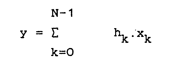
Le produit peut s'écrire sous la forme :![]()

![]()
La transformation de l'équation (1) donne, en notation matricielle (2) :
Chaque coefficient yℓ est donc de la forme:
Chaque coefficient peut donc être calculé en arithmétique distribuée.Each coefficient can therefore be calculated in distributed arithmetic.
Les nombres xi sont représentés chacun par un nombre binaire constitué de bits xij, avec j = 0,..., B-1. On considérera maintenant deux possibilités de représentation :The numbers x i are each represented by a binary number consisting of bits xij, with j = 0, ..., B-1. We will now consider two possibilities of representation:
Dans ce cas, on a :
On arrive dans ce cas à la représentation suivante de yℓ :
Dans cette équation (5), la double sommation est calculée par une succession de décalages et d'additions de termes élémentaires, constitués par l'expression entre parenthèses. Chaque terme est constitué par le produit direct du vecteur aℓ par plusieurs bits successifs xij, avec i = 0,..., 2n-1. On peut désigner par fℓla famille de fonctions correspondant chacune à l'expression entre parenthèses :
Chaque variable u; étant un bit, elle ne peut prendre que deux valeurs différentes, de sorte que chaque fonction fℓ peut prendre
- 22 n valeurs différentes. Toutes ces valeurs peuvent être stockées dans une mémoire morte de
- 22n mots de m bits chacun pour une fonction nécessitant une dynamique de m bits. Le calcul de chaque valeur de yℓ peut s'effectuer alors avec le montage de constitution simple illustré en Figure 1, exigeant cependant une mémoire morte de capacité égale à
- 22n mots pour chaque yi, ce qui peut atteindre un volume très élevé.
- 2 2 n different values. All these values can be stored in a ROM of
- 2 2n words of m bits each for a function requiring a dynamic range of m bits. The calculation of each value of y ℓ can then be carried out with the simple constitution assembly illustrated in FIG. 1, however requiring a read only memory with a capacity equal to
- 2 2n words for each y i , which can reach a very high volume.
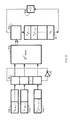
Sur la Figure 1, la mémoire morte 10 est montée pour recevoir, à chaque coup d'une horloge 12, une adresse constituée par la valeur des variables ui. Ces variables prendront successivement les valeurs xijcorrespondant successivement à i=0,..., 2n-1 pour toutes les valeurs de j de 0 à B-1, en provenance de registres 14. La sortie de la mémoire 10 est appliquée à l'une des entrées d'un accumulateur constituant additionneur-soustracteur 16. L'autre entrée reçoit la sortie d'un multiplieur par deux 18 (circuit de décalage de la virgule) auquel est appliquée la sortie de l'additionneur-soustracteur. Ce dernier effectue une addition ou une soustraction du contenu de la mémoire morte 10 à la position correspondant à la configuration binaire d'entrée, fournie par les registres 14, conformément à l'équation (5).In FIG. 1, the read only
On voit qu'après B coups d'horloge, le contenu de l'accumulateur de sortie est égal à yℓ.We see that after B clock ticks, the content of the output accumulator is equal to y ℓ .
Le calcul complet du produit de polynômes nécessite une installation comportant, en parallèle, 2nensembles du genre montré en figure 1, comprenant chacun une mémoire morte 10 et un additionneur-soustracteur 16. Tous ces ensembles reçoivent les adresses constituées par les bits de même poids des mots d'entrée.The complete calculation of the product of polynomials requires an installation comprising, in parallel, 2 sets of the kind shown in FIG. 1, each comprising a read only
Etant donné que les adresses sont les mêmes pour toutes les fonctions, les mémoires 10 des 2n différents ensembles peuvent être regroupées.Since the addresses are the same for all the functions, the
A titre d'exemple, pour n = 3, B = 8 et m = 14, (c'est-à-dire dans le cas où la fonction doit être quantifiée sur quatorze bits), on a besoin de huit mémoires mortes de chacune 256 mots de quatorze bits. Il faut également disposer de huit additionneurs-soustracteurs de chacun seize bits. Le résultat est obtenu en huit coups d'horloge.For example, for n = 3, B = 8 and m = 14, (that is to say in the case where the function must be quantized over fourteen bits), we need eight read-only memories of each 256 words of fourteen bits. Eight adders and subtractors of each sixteen bits are also required. The result is obtained in eight clock strokes.
La mémoire morte 10 correspondant à la fonction fℓ, telle que définie par l'équation (6), présente une certaine redondance, certains éléments résultant d'autres par multiplication par un nombre affecté d'un signe. Si on souhaite réduire la taille de la mémoire 10 nécessaire au calcul de f2, au prix d'une arithmétique un peu plus complexe, il suffit de faire apparaître la redondance en représentant les nombres xi, non plus en complément à deux, mais en utilisant un "code interne modifié", ou CIM, qui sera maintenant défini.The read-
Si on désigne par x'ij, avec j = 1,..., ℓ, la représentation d'un nombre xj en CIM, la contrepartie de l'équation (4) qui fournissait la représentation de xi en complément à deux, est :

En reportant la représentation de x; en CIM dans l'équation (3), on obtient :
Cette équation peut être mise sous une forme permettant de réduire le nombre de paramètres dont dépend la fonction fℓ si on pose εij = x'ij-X'ij, εijétant toujours égal soit à +1, soit à -1. La fonction fℓà stocker en mémoire peut alors s'écrire :
Etant donné que εij vaut + 1 ou -1, on peut mettre ε0j en facteur (un résultat comparable serait obtenu avec un autre facteur ε), et on a alors :
Pour simplifier la notation, on peut écrire :
- εij · ε0j = ηij,
- et on a alors :

- εij · ε0j = ηij,
- and we then have:
On constate que la fonction f'ℓ ne dépend plus que de 2n-1 paramètres et ne prend plus que 22n-1 valeurs différentes. La taille de la mémoire nécessaire est divisée par deux par rapport au cas du codage en complément à deux. Il s'agit là d'un avantage qui sera important si la mémoire est volumineuse. Dans le cas de mémoires de capacité limitée, la réduction de volume de mémoire ne justifiera pas l'allongement de la durée du calcul et la complexité accrue des opérations arithmétiques, bien que l'accroissement de complexité soit faible; en effet, les changements à apporter au schéma de principe montré en Figure 1 sont réduits. Il suffit :
- - d'une porte OU EXCLUSIF (ou XOR) entre soj et εij pour passer des variables εij aux variables ηij, si on suppose que l'état logique 0 correspond à εij = -1 et l'état logique 1 à εij = 1 ;
- - d'un circuit de changement de signe du mot qui sort de la mémoire morte si ε0j est égal à 0, la valeur à additionner dans l'accumulateur étant le résultat d'une opération OU EXCLUSIF entre ε0j et les bits qui sortent de la mémoire.
- - of an EXCLUSIVE OR gate (or XOR) between soj and εij to pass from variables εij to variables ηij, if we suppose that the logical state 0 corresponds to εij = -1 and the
logical state 1 to εij = 1; - - a circuit for changing the sign of the word leaving the read-only memory if ε0j is equal to 0, the value to be added in the accumulator being the result of an EXCLUSIVE OR operation between ε0j and the bits leaving the memory.
Le terme supplémentaire
Dans le cas du calcul d'un produit de polynômes, les fonctions fℓ et fℓ+1 définies par l'équation (10) ne sont pas indépendantes.In the case of the calculation of a product of polynomials, the functions f ℓ and f ℓ + 1 defined by equation (10) are not independent.
En effet,
fℓ+1 (ε0j, ε1j,...,ε2n-1,j) = fℓ(ε1j,ε2j,...,ε2n-1j,-ε0j)Indeed,
f ℓ + 1 (ε0j, ε1j, ..., ε2n-1, j) = f ℓ (ε1j, ε2j, ..., ε2n-1j, -ε0j)
Cette constatation permet de diminuer la mémoire nécessaire pour le calcul d'un produit de polynômes en utilisant l'arithmétique distribuée et le code CIM. En effet, -soj est représentable en CIM à l'aide d'un bit, constitué par l'inversion du symbole logique correspondant à εoj. L'ensemble du produit de polynômes yε, avec ℓ = 0,..., 2n-1 peut donc être calculé à l'aide d'un circuit du type montré en Figure 2. Sur ce circuit, les éléments déjà représentés en Figure 1 sont désignés par le même numéro de référence affecté de l'indice a. On supposera encore que ei = -1 est représenté par l'état logique 0 tandis que ei = + 1 est représenté par l'état logique 1.This observation makes it possible to reduce the memory necessary for the calculation of a product of polynomials using distributed arithmetic and the CIM code. Indeed, -soj is representable in CIM using a bit, constituted by the inversion of the logical symbol corresponding to εoj. The whole product of polynomials yε, with ℓ = 0, ..., 2n-1 can therefore be calculated using a circuit of the type shown in Figure 2. On this circuit, the elements already represented in Figure 1 are designated by the same reference number assigned to the index a. We will also assume that e i = -1 is represented by logical state 0 while ei = + 1 is represented by
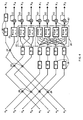
Tous les 2n coups d'horloge, les registres 14a chargent un bit de chaque mot xi dans le registre 20. Ce registre 20 a pour fonction d'adresser la mémoire morte 10a
de 2 2 n mots de m bits. Cette mémoire 10a peut être la même que l'une des mémoires 10 de la figure 1. A chaque coup d'horloge, le registre 20, qui comporte 2npositions de un bit, est décalé. Le bit sortant du registre 20 est réinjecté à l'entrée du registre, après inversion dans un inverseur 22. A chaque coup d'horloge, la mémoire morte 10a fournit en sortie :
- fo (ε0, ε1, .., ε2n-1), puis
fi (ε0, ..., ε2n-1), puis f2, ... etc.Every 2n clock ticks, the
of 2 2 n words of m bits. This
- fo (ε 0 , ε 1 , .., ε 2n-1 ), then
fi (ε 0 , ..., ε 2n-1 ), then f 2 , ... etc.
Les valeurs fo, f1, etc sont accumulées, chaque fois avec les valeurs correspondant à la contribution des bits précédents des mots d'entrée, au calcul de l'échantillon de sortie concerné. Pour cela, la sortie de la mémoire est encore reliée à un additionneur 16a formant accumulateur. Mais ce dernier, au lieu d'être rebouclé directement par le circuit multiplieur 18a, attaque un registre à décalage 24 comportant 2n positions de chacune m + n bits (ou moins, si 'on profite du décalage pour effectuer une (troncature).The values fo, f 1 , etc. are accumulated, each time with the values corresponding to the contribution of the preceding bits of the input words, to the calculation of the output sample concerned. For this, the memory output is also connected to an
Après B. 2n coups d'horloge, le registre à décalage 24 contiendra les échantillons y0, ..., y2n-1.After B. 2 n clock ticks, the
On voit que dans ce cas le polynôme complet est calculé en B. 2n coups d'horloge, alors qu'il suffisait de B coups d'horloge dans le cas de la figure 1. Mais, par contre, il suffit d'une seule mémoire 10a au lieu de 2n mémoires.We see that in this case the complete polynomial is calculated in B. 2n clock ticks, while it was enough B clock ticks in the case of Figure 1. But, on the other hand, it only takes one
Toutes les solutions intermédiaires sont évidemment possibles, suivant la vitesse recherchée. Par exemple, en utilisant deux mémoires mortes de chacune
2 2 n mots, le calcul est effectué en B. 2n-i coups d'horloge.All intermediate solutions are obviously possible, depending on the speed sought. For example, using two read only memories each
2 2 n words, the calculation is performed in B. 2n-i clock ticks.
Par ailleurs, les schémas des figures 1 et 2 supposent que le calcul s'effectue avec le bit de poids fort en tête dans les registres 14 et 14a. On pourrait tout aussi bien faire intervenir le bit de poids faible en tête, en remplaçant les multiplieurs 18 et 18a par des diviseurs par deux, c'est-à-dire en faisant le décalage en sens opposé.Furthermore, the diagrams in FIGS. 1 and 2 assume that the calculation is carried out with the most significant bit in the lead in the
On décrira maintenant, mais uniquement dans le cas particulier de la transformation en cosinus discret ou TCD, des dispositifs permettant de réduire la complexité des calculs et la taille des mémoires requises pour le calcul de toute transformée discrète d'un signal représenté par N=2n échantillons numériques, lorsque la transformée est telle que l'on puisse effectuer une décomposition de la transformée en produits de polynômes, puis les calculer en arithmétique distribuée. Le gain sur la complexité sera notamment dû à ce que les pré-calculs nécessaires avant de faire appel à un adressage en mémoire morte sont effectués en arithmétique série.We will now describe, but only in the particular case of the transformation in discrete cosine or TCD, devices making it possible to reduce the complexity of the calculations and the size of the memories required for the calculation of any discrete transform of a signal represented by N = 2 n digital samples, when the transform is such that we can decompose the transform into products of polynomials, then calculate them in distributed arithmetic. The gain in complexity will in particular be due to the fact that the pre-calculations necessary before calling for read-only memory addressing are performed in serial arithmetic.
On a déjà montré, dans la demande de brevet FR EN 86 01629 du demandeur, que la transformée en cosinus discret, dont la notation habituelle est :
- avec k = 0, ..., N -1
peut se mettre sous la forme :

- with k = 0, ..., N -1
can take the form:
La simplification apportée par l'invention part de la constatation qu'une TCD, comme d'ailleurs d'autres transformations discrètes d'un signal représenté par 2néchantillons, présente les propriétés que :
- les termes impairs X2k+ s'obtiennent, à un signe près, par un produit de deux polynômes ayant une longueur 2n-1;
- les termes pairs X2k peuvent être obtenus en sortie d'une transformée de longueur moitié.
- the odd terms X2k + are obtained, to the nearest sign, by a product of two polynomials having a length 2n-1;
- the even terms X 2k can be obtained at the end of a half length transform.
La seconde propriété est bien connue. La première peut être démontrée. Pour cela, on considère la fonction
- qui est la représentation d'un terme impair, d'ordre 2k+1, de la TCD Xk. Elle a la propriété suivante :
- - les N/2 premiers termes, Yk, pour k = 0,..., -1, sont égaux aux N/2 premiers termes impairs de la transformée,
- - les N/2 termes suivants sont opposés aux N/2 premiers termes, ce qui peut s'écrire :
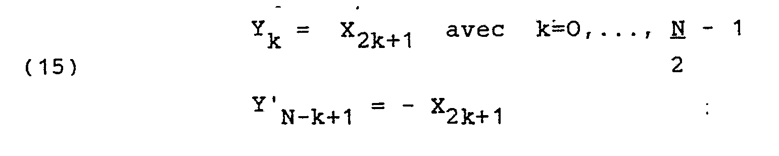
- which is the representation of an odd term, of order 2k + 1, of the TCD X k . It has the following property:
- - the first N / 2 terms, Y k , for k = 0, ..., -1, are equal to the first N / 2 odd terms of the transform,
- - the following N / 2 terms are opposite to the first N / 2 terms, which can be written:
La fonction Yk donnée en (14) est symétrique en i et k. En conséquence, les mêmes changements de variables que ceux exposés dans la demande FR no86 01 629, de x à x', puis à x", s'appliquent pour i et k, ce qui permet d'arriver à une représentation Y'k de Yk qui est :

Le polynôme constitué de tous les termes impairs Y"k peut s'écrire :
- (19) Y (z) = X (z), W (z) mod (z N-1) en posant :
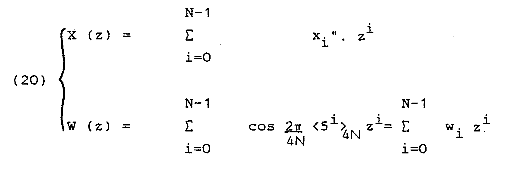
- (19) Y (z) = X (z), W (z) mod (z N-1) by posing:
Les polynômes Y (z) et W (z) présentent une redondance représentée par l'équation (15). De plus on voit que
- Y"k+N/2 = -Y"k
- Wi+N/2 = -Wi
- Y " k + N / 2 = -Y" k
- Wi + N / 2 = -W i
Tous les X2k+sont indépendants entre eux. En conséquence, les valeurs successives prises par Y"ℓavec ℓ = 0,..., -1,seront égales à toutes les valeurs de X2k+ 1, à un signe près. En effet, il y aura identité pour k < N/2. Il y aura changement de signe lorsque les permutations inverses de celles des équations (16) et (17) pour Yk" avec k=0, ..., ![]()
![]()
Si on écrit les équations (18), (19) et (20) modulo (zN/2+1) on obtient :

Cette constatation fait apparaître qu'une DCT de longueur N = 2n peut, au lieu de faire l'objet du calcul direct en arithmétique distribuée de la matrice (2), ce qui exige une mémoire morte de
- 2 2 n mots, être calculée en au moins deux étapes :
- - une étape de pré-calcul, effectuée à l'aide de "papillons" classiques en matière de calcul de transformées permettant d'obtenir d'une part les éléments de calcul des termes pairs, d'autre part un produit de polynômes représentant les termes impairs.
- - une étape de calcul des termes impairs, en arithmétique distribuée, ne nécessitant plus qu'une mémoire adressable de
-

- 2 2 n words, be calculated in at least two steps:
- a pre-calculation step, carried out using conventional "butterflies" in the field of transform calculations, making it possible on the one hand to obtain the elements for calculating even terms, on the other hand a product of polynomials representing the odd terms.
- - a step of calculating the odd terms, in distributed arithmetic, requiring only an addressable memory of
-
Dans le cas de transformée relativement courte, par exemple de longueur 8, l'accroissement de complexité qu'implique la mise en C.I.M. ne sera pas justifié. On pourra alors utiliser le calcul en complément à deux.In the case of a relatively short transform, for example of
La figure 3 montre la constitution de principe d'un dispositif de calcul d'une TCD de longueur 8, les échantillons étant codés en complément à deux. La partie représentée correspond à un seul des termes y et le dispositif complet comportera donc huit circuits.FIG. 3 shows the basic construction of a device for calculating a TCD of
Les échantillons x0, ..., x7 sont appliqués à un premier étage d'opérateurs "papillons" 26 fournissant :
- la somme des termes d'entrée sur une première sortie,
- la différence des termes d'entrée sur une seconde sortie.
- the sum of the entry terms on a first exit,
- the difference of the input terms on a second output.
Ces opérateurs 26 constituent un circuit de pré-calcul en arithmétique série, c'est-à-dire effectuée bit par bit, sur des mots en parallèle. Les sorties soustractives des papillons sont appliquées à titre d'adresse à une mémoire morte 28 qui va effectuer le calcul de la matrice (2) en arithmétique distribuée, sur une longueur moitié de celle de la transformée complète. Dans le cas particulier de la longueur 8, la mémoire 28 doit effectuer un produit de polynômes de longueur 4 modulo Z 4 + 1. Cette mémoire 28 devra donc avoir une capacité de 64 mots de m bits, m étant le nombre de bits qu'impose la dynamique recherchée pour la fonction de sortie.These
La même séquence de pré-calcul puis de calcul en arithmétique distribuée peut être répétée sur les termes pairs restants. Dans le mode de réalisation montré en figure 3, on trouve une seconde couche 30 d'opérateurs papillons, dont les sorties soustractives attaquent les entrées d'adressage d'une mémoire morte 32 qui va réaliser un produit de polynômes modulo z2+ 1. La mémoire 32 n'aura à contenir que 8 mots de m bits. Enfin le dernier opérateur 34 permet d'obtenir les termes restants.The same sequence of pre-calculation then of calculation in distributed arithmetic can be repeated on the remaining even terms. In the embodiment shown in FIG. 3, there is a
Dans la pratique, le circuit pourra avoir la constitution montrée en figure 4, où on retrouve les mémoires mortes 28 et 32.In practice, the circuit may have the constitution shown in FIG. 4, where there are the read only
Ces mémoires sont fractionnées et toutes les fractions ont la même capacité de mots de m bits : par exemple, la mémoire 28 peut être constituée de quatre fractions de 16 mots, alors que la mémoire 32 est formée de deux fractions de 4 mots et la mémoire 36 de calcul du terme X4 d'un seul mot. Des éléments de retard 38 tous identiques, pouvant être constitués par des registres à décalage à une position binaire munis d'une entrée d'horloge non représentée, sont interposés sur les entrées des mémoires pour fournir chacun un retard d'une période T d'horloge et permettre de pipeliner le système. Enfin, chaque fraction de mémoire, affectée à un terme X particulier, alimente un accumulateur 40 constitué par un circuit additionneur rebouclé sur lui-même, l'ensemble des additionneurs élémentaires constituant un opérateur parallèle.These memories are divided and all the fractions have the same capacity of words of m bits: for example, the
Au lieu d'utiliser un circuit fonctionnant en complément à deux, on peut préalablement coder les échantillons en CIM à l'aide d'un circuit dont la constitution découle directement de la nature du codage, tel que défini par les formules (7) et (8). Dans ce cas, il est possible :
- - de diviser par deux la capacité des mémoires,
- - de donner une constitution identique à toutes les fractions de mémoire de même taille (les quatre fractions de la mémoire 28 par exemple) ou d'utiliser une seule fraction par mémoire, en l'utilisant à plusieurs reprises successivement, au prix d'une réduction de la vitesse de calcul.
- - to halve the capacity of the memories,
- - to give an identical constitution to all memory fractions of the same size (the four fractions of
memory 28 for example) or to use a single fraction per memory, by using it several times successively, at the cost of one reduction in calculation speed.
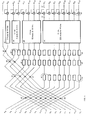
Toujours dans le cas d'un codage en complément à deux, le dispositif de calcul d'une TCD de longueur 16 peut avoir la constitution montrée en figure 5 où on retrouve une première couche de huit opérateurs papillons 42 qui fournissent :
- - des termes qui sont calculés en arithmétique distribuée à l'aide d'une mémoire morte 44 à 256 positions et 112 fils de sortie, fournissant les huit termes impairs sur 14 bits, trois éléments de retard 46 étant interposés sur chaque entrée pour assurer la synchronisation des sorties par retard de trois périodes d'horloge (c'est-à-dire, du nombre de périodes requis pour le fonctionnement du canal le plus lent, comportant quatre papillons en cascade).
- - des termes qui sont soumis à de nouveaux pré-calculs de mise sous forme d'un produit de polynômes. Pour cela, une seconde couche de papillons 49 combine les termes pour donner naissance à ceux qui vont:
- . donner directement naissance à des termes maintenant "impairs"
- X2.1 , X 2.3, X 2.5, X 2.7
. pouvoir faire l'objet d'au moins un nouveau fractionnement : - X0, X2.2, X 2.2.2, et X2.2.3
- X2.1 , X 2.3, X 2.5, X 2.7
- terms which are calculated in distributed arithmetic using a read-
only memory 44 with 256 positions and 112 output wires, providing the eight odd terms on 14 bits, threedelay elements 46 being interposed on each input to ensure the synchronization of the outputs by delay of three clock periods (that is to say, of the number of periods required for the operation of the slowest channel, comprising four butterflies in cascade). - - terms which are subjected to new pre-computations in the form of a product of polynomials. For this, a second layer of
butterflies 49 combines the terms to give birth to those who go: - . give birth directly to now "odd" terms
- X2.1, X 2.3, X 2.5, X 2 . 7
. be able to be subject to at least one new fractionation: - X 0 , X 2 . 2 , X 2 . 2 . 2 , and X 2 . 2 . 3
- X2.1, X 2.3, X 2.5, X 2 . 7
Les éléments de calcul des termes maintenant considérés comme impairs sont ap liqués par l'intermédiaire d'éléments de retard 46, à une mémoire morte 48 de 16 mots de 4 x 14 bits, munie de 16 x 14 fils de sortie. Le même processus est suivi après une nouvelle décomposition à l'aide de papillons 50, puis 52,de précalcul, à l'aide de mémoires mortes adressables 54 et 56, tous les fils de sortie des mémoires 44, 48, 54 et 56 attaquant des additionneurs-accumulateurs 58 qui fournissent les termes X de la transformée, par exemple sur 16 bits.The elements for calculating the terms now considered to be odd are settled by means of
Claims (8)
caractérisé en ce que,
ladite transformée étant d'un type tel que, par une combinaison desdits échantillons qui fournit d'une part la somme, d'autre part la différence des échantillons pris deux à deux, elle soit réductible à deux transformées de longueur moitié dont l'une est encore réductible en deux transformées de longueur moitié, si N est une puissance de 2,
le dispositif comprend : un ensemble de circuits élémentaires (26) en arithmétique série (bit par bit) fournissant les sommes et différences des échantillons d'entrée deux à deux ; un circuit (28) relié aux circuits élémentaires (26) pour recevoir les différences entre échantillons d'entrée et déterminer directement en arithmétique distribuée la moitié des échantillons de la transformée complète ; et des moyens de calcul (30-34) distincts et différents dudit circuit et reliés aux circuits élémentaires, fournissant l'autre moitié des échantillons de la transformée complète.1. Device for determining the discrete transform of a signal X represented by N binary digital samples xo, ..., Xi, ... X N - 1 ,
characterized in that,
said transform being of a type such that, by a combination of said samples which provides on the one hand the sum, on the other hand the difference of the samples taken two by two, it can be reduced to two transforms of half length, one of which is still reducible into two half length transforms, if N is a power of 2,
the device comprises: a set of elementary circuits (26) in serial arithmetic (bit by bit) providing the sums and differences of the input samples two by two; a circuit (28) connected to elementary circuits (26) for receiving the differences between input samples and determining directly in distributed arithmetic half of the samples of the complete transform; and calculation means (30-34) distinct and different from said circuit and connected to the elementary circuits, providing the other half of the samples of the complete transform.
2 2 n valeurs, un circuit d'adressage de la mémoire successivement par chacun des bits successifs des échantillons appliqués à la mémoire et un circuit accumulateur (16) rebouclé par un multiplieur (ou diviseur) par deux (18).3. Device according to claim 1 or 2, characterized in that said circuit (28) comprises N = 2 sets comprising each of a read only memory (10) for storing
2 2 n values, a circuit for addressing the memory successively by each of the successive bits of the samples applied to the memory and an accumulator circuit (16) looped back by a multiplier (or divider) by two (18).
Applications Claiming Priority (2)
| Application Number | Priority Date | Filing Date | Title |
|---|---|---|---|
| FR8612431A FR2603719B1 (en) | 1986-09-04 | 1986-09-04 | DEVICE FOR DETERMINING THE DIGITAL TRANSFORM OF A SIGNAL |
| FR8612431 | 1986-09-04 |
Publications (2)
| Publication Number | Publication Date |
|---|---|
| EP0259231A1 true EP0259231A1 (en) | 1988-03-09 |
| EP0259231B1 EP0259231B1 (en) | 1992-03-04 |
Family
ID=9338695
Family Applications (1)
| Application Number | Title | Priority Date | Filing Date |
|---|---|---|---|
| EP87401968A Expired - Lifetime EP0259231B1 (en) | 1986-09-04 | 1987-09-02 | Device for the determination of the digital transform of a signal |
Country Status (5)
| Country | Link |
|---|---|
| US (1) | US4831574A (en) |
| EP (1) | EP0259231B1 (en) |
| JP (1) | JPS6382546A (en) |
| DE (1) | DE3777021D1 (en) |
| FR (1) | FR2603719B1 (en) |
Cited By (2)
| Publication number | Priority date | Publication date | Assignee | Title |
|---|---|---|---|---|
| EP0621543A2 (en) * | 1993-04-19 | 1994-10-26 | General Instrument Corporation Of Delaware | Inverse discrete cosine transform processor |
| WO1999053419A3 (en) * | 1998-04-09 | 2000-01-06 | Koninkl Philips Electronics Nv | Device for converting series of data elements |
Families Citing this family (12)
| Publication number | Priority date | Publication date | Assignee | Title |
|---|---|---|---|---|
| DE3900349A1 (en) * | 1989-01-07 | 1990-07-12 | Diehl Gmbh & Co | CIRCUIT FOR THE REAL-TIME PERFORMANCE OF THE FAST FOURIER TRANSFORMATION |
| KR920008270B1 (en) * | 1990-04-03 | 1992-09-26 | 정호선 | Ic for discrete cosine transform implemented by neural network |
| FR2681962B1 (en) * | 1991-09-30 | 1993-12-24 | Sgs Thomson Microelectronics Sa | METHOD AND CIRCUIT FOR PROCESSING DATA BY COSINUS TRANSFORM. |
| US5539836A (en) * | 1991-12-20 | 1996-07-23 | Alaris Inc. | Method and apparatus for the realization of two-dimensional discrete cosine transform for an 8*8 image fragment |
| US5394349A (en) * | 1992-07-10 | 1995-02-28 | Xing Technology Corporation | Fast inverse discrete transform using subwords for decompression of information |
| US5339265A (en) * | 1992-08-31 | 1994-08-16 | University Of Maryland At College Park | Optimal unified architectures for the real-time computation of time-recursive discrete sinusoidal transforms |
| US5408425A (en) * | 1993-05-25 | 1995-04-18 | The Aerospace Corporation | Split-radix discrete cosine transform |
| US6112219A (en) * | 1993-09-23 | 2000-08-29 | Realnetworks, Inc. | Method and apparatus for performing fast discrete cosine transforms and fast inverse discrete cosine transforms using look-up tables |
| JP2997613B2 (en) * | 1993-10-26 | 2000-01-11 | 株式会社東芝 | Discrete cosine transformer |
| US5818535A (en) * | 1996-09-30 | 1998-10-06 | Alaris, Inc. | Method and apparatus for adaptive hybrid motion video compression and decompression |
| US6006245A (en) * | 1996-12-20 | 1999-12-21 | Compaq Computer Corporation | Enhanced fast fourier transform technique on vector processor with operand routing and slot-selectable operation |
| US8351295B2 (en) * | 2007-06-01 | 2013-01-08 | Second Wind Systems, Inc. | Waterproof membrane cover for acoustic arrays in sodar systems |
Family Cites Families (4)
| Publication number | Priority date | Publication date | Assignee | Title |
|---|---|---|---|---|
| US4385363A (en) * | 1978-12-15 | 1983-05-24 | Compression Labs, Inc. | Discrete cosine transformer |
| US4449194A (en) * | 1981-09-25 | 1984-05-15 | Motorola Inc. | Multiple point, discrete cosine processor |
| FR2561010B1 (en) * | 1984-03-09 | 1986-09-12 | Cit Alcatel | PROCESSOR FOR CALCULATING A DISCRETE COSINUS TRANSFORM |
| FR2581463B1 (en) * | 1985-05-03 | 1989-09-08 | Thomson Csf | COSINUS TRANSFORM COMPUTING DEVICES, CODING DEVICE AND IMAGE DECODING DEVICE COMPRISING SUCH COMPUTING DEVICES |
-
1986
- 1986-09-04 FR FR8612431A patent/FR2603719B1/en not_active Expired - Lifetime
-
1987
- 1987-09-02 EP EP87401968A patent/EP0259231B1/en not_active Expired - Lifetime
- 1987-09-02 DE DE8787401968T patent/DE3777021D1/en not_active Expired - Lifetime
- 1987-09-03 JP JP62221784A patent/JPS6382546A/en active Pending
- 1987-09-04 US US07/092,986 patent/US4831574A/en not_active Expired - Fee Related
Non-Patent Citations (2)
| Title |
|---|
| IEEE TRANSACTIONS ON COMPUTERS, vol. 19, no. 9, septembre 1972, pages 1026-1027, New York, US; V.J. REJCHRT: "Signal flow graph and a fortran program for Haar-Fourier transform" * |
| IEEE TRANSACTIONS ON COMPUTERS, vol. C-32, no. 12, décembre 1983, pages 1128-1136, IEEE, New York, US; P. CHOW et al.: "A pipelined distributed arithmetic PFFT processor" * |
Cited By (4)
| Publication number | Priority date | Publication date | Assignee | Title |
|---|---|---|---|---|
| EP0621543A2 (en) * | 1993-04-19 | 1994-10-26 | General Instrument Corporation Of Delaware | Inverse discrete cosine transform processor |
| EP0621543A3 (en) * | 1993-04-19 | 1995-08-09 | Gen Instrument Corp | Inverse discrete cosine transform processor. |
| WO1999053419A3 (en) * | 1998-04-09 | 2000-01-06 | Koninkl Philips Electronics Nv | Device for converting series of data elements |
| US6772183B1 (en) | 1998-04-09 | 2004-08-03 | Koninklijke Philips Electronics N.V. | Device for converting input data to output data using plural converters |
Also Published As
| Publication number | Publication date |
|---|---|
| US4831574A (en) | 1989-05-16 |
| EP0259231B1 (en) | 1992-03-04 |
| JPS6382546A (en) | 1988-04-13 |
| FR2603719B1 (en) | 1991-10-31 |
| DE3777021D1 (en) | 1992-04-09 |
| FR2603719A1 (en) | 1988-03-11 |
Similar Documents
| Publication | Publication Date | Title |
|---|---|---|
| EP0248729B1 (en) | Monodimensional cosine transform calculators and image coding and decoding devices using such calculators | |
| EP3084588B1 (en) | Signal processing module, especially for a neural network and a neuronal circuit | |
| EP0259231A1 (en) | Device for the determination of the digital transform of a signal | |
| EP3660849A1 (en) | Memory circuit suitable for performing computing operations | |
| EP0204603B1 (en) | Fast calculating of the direct or reverse cosine transform of a discrete signal | |
| EP3809287B1 (en) | Method for simplifying a filter and associated devices | |
| EP0262032B1 (en) | Binary adder having a fixed operand, and a parallel/serial multiplier comprising such an adder | |
| EP3809288B1 (en) | Method for filtering with zero latency and associated devices | |
| EP3809286B1 (en) | Method for filtering with reduced latency and associated devices | |
| FR2958100A1 (en) | ORCHID MEASUREMENT METHOD OF CORRESPONDING CHAOTIC SEQUENCES AND COMPUTER PROGRAM | |
| EP0437876B1 (en) | Programmable serial multiplier | |
| FR2588680A1 (en) | DEVICE FOR CALCULATING A DISCRETE FOURIER TRANSFORMER, AND ITS APPLICATION TO PULSE COMPRESSION IN A RADAR SYSTEM | |
| FR2724741A1 (en) | ELECTRONIC CIRCUIT FOR MODULAR CALCULATION IN A FINISHED BODY | |
| FR2598833A1 (en) | APPARATUS FOR ESTIMATING THE SQUARE ROOT OF DIGITAL SAMPLES | |
| EP0478431A1 (en) | Digital signal coding method and circuit for calculating scalar products of vectors and corresponding discrete cosinus transform | |
| EP0237382B1 (en) | Digital sampled signal cosine transforming device | |
| EP0476592A2 (en) | Address generator for the data storage of a processor | |
| EP0327445A1 (en) | Generalised digital multiplier, and digital filter using this multiplier | |
| FR2741977A1 (en) | APPARATUS FOR TRANSFORMING A TWO-DIMENSIONAL DISCRETE COSINUS | |
| EP0175623A1 (en) | Device for the real-time processing of a digital signal by convolution | |
| FR2716321A1 (en) | Method and device for vector quantization of a digital signal, in particular applied to the compression of digital images. | |
| FR2761550A1 (en) | DIGITAL FILTER FOR FRACTIONAL DELAYS | |
| FR2731813A1 (en) | COMPUTER PROCESSOR USING LOGARITHMIC CONVERSION AND METHOD OF USING THE SAME | |
| EP0329572B1 (en) | Multiplier of binary numbers having a very large number of bits | |
| FR2563349A1 (en) | Systolic matrix multiplier for digital data processing |
Legal Events
| Date | Code | Title | Description |
|---|---|---|---|
| PUAI | Public reference made under article 153(3) epc to a published international application that has entered the european phase |
Free format text: ORIGINAL CODE: 0009012 |
|
| AK | Designated contracting states |
Kind code of ref document: A1 Designated state(s): DE GB NL |
|
| 17P | Request for examination filed |
Effective date: 19880615 |
|
| 17Q | First examination report despatched |
Effective date: 19900118 |
|
| GRAA | (expected) grant |
Free format text: ORIGINAL CODE: 0009210 |
|
| AK | Designated contracting states |
Kind code of ref document: B1 Designated state(s): DE GB NL |
|
| GBT | Gb: translation of ep patent filed (gb section 77(6)(a)/1977) | ||
| REF | Corresponds to: |
Ref document number: 3777021 Country of ref document: DE Date of ref document: 19920409 |
|
| PLBE | No opposition filed within time limit |
Free format text: ORIGINAL CODE: 0009261 |
|
| STAA | Information on the status of an ep patent application or granted ep patent |
Free format text: STATUS: NO OPPOSITION FILED WITHIN TIME LIMIT |
|
| 26N | No opposition filed | ||
| PGFP | Annual fee paid to national office [announced via postgrant information from national office to epo] |
Ref country code: GB Payment date: 19940826 Year of fee payment: 8 |
|
| PGFP | Annual fee paid to national office [announced via postgrant information from national office to epo] |
Ref country code: DE Payment date: 19940929 Year of fee payment: 8 |
|
| PGFP | Annual fee paid to national office [announced via postgrant information from national office to epo] |
Ref country code: NL Payment date: 19940930 Year of fee payment: 8 |
|
| PG25 | Lapsed in a contracting state [announced via postgrant information from national office to epo] |
Ref country code: GB Effective date: 19950902 |
|
| PG25 | Lapsed in a contracting state [announced via postgrant information from national office to epo] |
Ref country code: NL Effective date: 19960401 |
|
| GBPC | Gb: european patent ceased through non-payment of renewal fee |
Effective date: 19950902 |
|
| PG25 | Lapsed in a contracting state [announced via postgrant information from national office to epo] |
Ref country code: DE Effective date: 19960601 |
|
| NLV4 | Nl: lapsed or anulled due to non-payment of the annual fee |
Effective date: 19960401 |