EP0263375A2 - A method and apparatus for detecting the motion of image in a television signal - Google Patents
A method and apparatus for detecting the motion of image in a television signal Download PDFInfo
- Publication number
- EP0263375A2 EP0263375A2 EP19870114034 EP87114034A EP0263375A2 EP 0263375 A2 EP0263375 A2 EP 0263375A2 EP 19870114034 EP19870114034 EP 19870114034 EP 87114034 A EP87114034 A EP 87114034A EP 0263375 A2 EP0263375 A2 EP 0263375A2
- Authority
- EP
- European Patent Office
- Prior art keywords
- signal
- interframe difference
- value
- adjacent interframe
- immediate
- Prior art date
- Legal status (The legal status is an assumption and is not a legal conclusion. Google has not performed a legal analysis and makes no representation as to the accuracy of the status listed.)
- Granted
Links
Images

Classifications
-
- H—ELECTRICITY
- H04—ELECTRIC COMMUNICATION TECHNIQUE
- H04N—PICTORIAL COMMUNICATION, e.g. TELEVISION
- H04N19/00—Methods or arrangements for coding, decoding, compressing or decompressing digital video signals
- H04N19/85—Methods or arrangements for coding, decoding, compressing or decompressing digital video signals using pre-processing or post-processing specially adapted for video compression
- H04N19/89—Methods or arrangements for coding, decoding, compressing or decompressing digital video signals using pre-processing or post-processing specially adapted for video compression involving methods or arrangements for detection of transmission errors at the decoder
-
- H—ELECTRICITY
- H04—ELECTRIC COMMUNICATION TECHNIQUE
- H04N—PICTORIAL COMMUNICATION, e.g. TELEVISION
- H04N7/00—Television systems
- H04N7/12—Systems in which the television signal is transmitted via one channel or a plurality of parallel channels, the bandwidth of each channel being less than the bandwidth of the television signal
- H04N7/122—Systems in which the television signal is transmitted via one channel or a plurality of parallel channels, the bandwidth of each channel being less than the bandwidth of the television signal involving expansion and subsequent compression of a signal segment, e.g. a frame, a line
- H04N7/125—Systems in which the television signal is transmitted via one channel or a plurality of parallel channels, the bandwidth of each channel being less than the bandwidth of the television signal involving expansion and subsequent compression of a signal segment, e.g. a frame, a line the signal segment being a picture element
-
- H—ELECTRICITY
- H04—ELECTRIC COMMUNICATION TECHNIQUE
- H04N—PICTORIAL COMMUNICATION, e.g. TELEVISION
- H04N7/00—Television systems
- H04N7/015—High-definition television systems
- H04N7/0152—High-definition television systems using spatial or temporal subsampling
Definitions
- the present invention relates to a method and an apparatus for detecting the motion of image in a band-width-compressed television transmission signal which does not include the interframe aliased portion in the lower frequency region, and particularly to a method and apparatus for the image motion detection intended for the decoder in the receiver for receiving the compressed television transmission signal.
- One of the methods for transmitting a television signal, particularly a high definition television signal, by bandwidth compression is the multiple subsampling transmission system which implements offset subsampling between frames and between fields.
- An example of this system called MUSE Multiple Sub-Nyquist Sampling Encoding
- MUSE Multiple Sub-Nyquist Sampling Encoding
- the MUSE system is described in detail in the technical study report of The Institute of Electronics and Communication Engineers of Japan, Graphic Engineering IE 84-72.
- subsampling cycles in two frames and therefore the receiver cannot use a difference signal for immediately adjacent frames (because of absent partner of comparison) and has to use a difference signal between next adjacent frames in detecting the motion of image, resulting in an inaccurate motion detection.
- the applicant of the present invention has proposed a multiple subsampling transmission system which implements the motion detection using the difference signal for immediately adjacent frames (refer to JP-A-61-264889 ).
- the above-mentioned proposal resides in the multiple subsampling transmission system which compresses the transmission bandwidth by offset subsampling between fields and between frames, wherein the television picture signal is initially subjected to interfield offset subsampling, and the resulting signal is processed with a low-pass filter having a cut-off frequency half the sampling frequency of interfield offset subsampling, and then the filtered signal is subjected to frequency conversion and interframe offset subsampling at a frequency lower than twice the low-pass filter cut-off frequency.
- the produced transmission signal does not include the interframe aliased portion in the lower frequency region, enabling a low-frequency component signal extracted in the receiver to produce the interframe difference signal (difference signal for immediately adjacent frames) as a motion signal, whereby accurate motion detection is accomplished.
- the decoder of the multiple subsampling transmission system without including the interframe aliased portion in the lower frequency region operates to switch the band of the immediate-adjacent interframe difference detection signal for producing the motion detection signal to a region which includes the aliased portion or a region which does not include to depending on the result of detection for the next-adjacent interframe difference (a difference between next adjacent frames).
- the switching operation in case the detected next-adjacent interframe difference is significant having a magnitude higher than the reference level, allows the band of the motion detecting immediate-adjacent interframe difference signal to be intermingled with a component higher than the cut-off frequency (e.g., 4 MHz) of the low-pass filter used in the decoder of the JP-A-264889/86,
- next-adjacent interframe difference signal when one (e.g., next-adjacent interframe difference signal) is used dominantly as the above-mentioned motion signal, the system becomes increasingly dependent on the dominating signal. For example, when small portions of picture move right and left due to the slow swing of the television camera or the like, the dominating next-adjacent interframe difference signal will be made valid or invalid alternately. If this phenomenon occurs at every frame, the pixelwise motion signal will become unstable, with its state changing in every frame.
- the motion signal is switched to match with the unstable dominating signal, resulting likely in a deteriorated picture. Therefore, it is necessary to use the above-mentioned three signals appropriately as a motion signal, instead of using one signal dominantly which causes the motion signal to become unstable.
- the image motion detection method of the present invention resides in the multiple sampling transmission system which transmits the television signal with its bandwidth compressed so as not to include the interframe aliased portion in the lower frequency region, wherein three signals including a next-adjacent interframe difference signal, immediate-adjacent interframe difference narrow-band signal without the interframe aliased portion and immediate-adjacent interframe difference broad-band signal with the interframe aliased portion are generated, the maximum-value is taken between prescribed two signals among the next-adjacent interframe difference signal or a signal related thereto, the immediate-adjacent interframe difference narrow-band signal or a signal related thereto, and the immediate-adjacent interframe difference broad-band signal or a signal related thereto, the minimum-value is taken between the resulting maximum-value signal and the remaining signal other than the above two signals, and the resulting minimum-value signal is validated as a motion signal which indicates the motion of image.
- the image motion detection apparatus of the present invention in intended for the decoder within a television receiver for decoding the television transmission signal which has been bandwidth compressed based on the multiple subsampling transmission system and does not include the interframe aliased portion in the lower frequency band.
- the decoder is premised to include a signal generation circuit for generating from the television transmission signal a next-adjacent interframe difference signal or a signal related thereto, an immediate-adjacent interframe difference narrow-band signal without the interframe aliased portion or a signal related thereto and an immediate-adjacent interframe difference broad-band signal with the interframe aliased portion, and the decoder further includes an image motion detecting device for detecting the motion of image in the transmission signal comprising a first maximum-value selection circuit which receives the next-adjacent interframe difference signal or the related signal and the immediate-adjacent interframe difference narrow-band signal or the related signal to select the maximum-value between the signals, and a
- the decoder arrangement includes a signal/sync detection circuit 1 which receives the transmission signal (interframe subsampling frequency: 16 MHz) without the interframe aliased portion in the lower frequency region supplied to a signal input terminal 12 and produces a synchronizing signal used for the synchronous control of the decoder.
- Shown by S1 is a switch for subsample shifting, and it inserts a motion-compensated 1-frame delayed signal provided by a frame memory 2 and motion compensation circuit 3 into the transmission signal received on the input terminal 12 to produce an interframe interpolated signal with a 32 MHz sampling frequency (on the line indicated by in the figure).
- the interframe interpolated signal from the switch S1 is entered to one input of a signal generation circuit 4, to an intrafield interpolation circuit 5 by way of a switch S2 which operates in unison with the switch S1, and to one input of a mixer 6.
- the signal generation circuit 4 has another input receiving the transmission signal from the input terminal 12, and it produces three signals, i.e., the next-adjacent interframe difference signal (a), immediate-adjacent interframe difference narrow-band signal (b) and immediate-adjacent interframe difference broad-band signal (c) as will be described later, necessary for the motion detection circuit 30 to produce the motion signal.
- the switch S2 extracts the signal only at the sampling point corresponding to the current field from the signal from the switch S1, the intrafield interpolation circuit 5 implements intrafield interpolation for the extracted signal, and the mixer 6 receives the resulting signal.
- the mixer 6 intermingles the motion picture system signal from the intrafield interpolation circuit 5 and the still picture system signal from the switch S1 depending on the amount of movement indicated by the output signal from the motion detection circuit 30.
- An interfield interpolation circuit 9 operates to interpolate the 1-field delayed signal provided by a field memory 7 and motion compensation circuit 8 into the output signal from the mixer 6, and the resulting interfield interpolated signal is fed to one input of a frequency converter/mixer 10.
- the frequency converter/mixer 10 has another input receiving a 32-MHz sampling signal from the mixer 6, and the circuit 10 converts its frequency to 48 MHz.
- the 48-MHz sampling signal is intermingled with the signal from the interfield interpolation circuit 9 depending on the amount of movement indicated by the output signal from the motion detection circuit 30, and the mixed signal is fed to a TCI (Time-Compressed Integration) decoder 11, by which the signal is transform deeplyed into an intended television signal and it is delivered to the output terminal.
- TCI Time-Compressed Integration
- a next-adjacent interframe difference signal detection circuit In the figure, indicated by 14 is a next-adjacent interframe difference signal detection circuit, with its two input terminals receiving the signals on lines and shown in Fig. 1. Indicated by 15 is a threshold circuit which validates the output signal from the next-adjacent interframe difference signal detection circuit 14 at a certain reference level to provide a next-adjacent interframe difference signal (a) at its output.
- the frame memory 16 receives the signal on line in Fig. 1 (the transmission signal with 16-MHz sampling frequency) and the subtracter 17 produces the immediate-adjacent interframe difference signal.
- the signal is fed through a first low-pass filter 18 with a wide pass band (e.g., -6 dB at 8 MHz) to become an immediate-adjacent interframe difference broad-band signal (c), and it is fed through a second low-pass filter 19 with a narrow pass band connected in cascade with the first low-pass filter 18 to become an immediate-adjacent interframe difference narrow-band signal (b).
- a first low-pass filter 18 with a wide pass band (e.g., -6 dB at 8 MHz) to become an immediate-adjacent interframe difference broad-band signal (c)
- a second low-pass filter 19 with a narrow pass band connected in cascade with the first low-pass filter 18 to become an immediate-adjacent interframe difference narrow-band signal (b).
- the immediate-adjacent interframe difference narrow-band signal (b) passing through the cascade connection of the first and second low-pass filters does not include the aliased porton between frames and is not responsive above 4 MHz, in contrast to the immediate-adjacent interframe difference broad-band signal (c) which includes the aliased portion between frames and is responsive even above 4 MHz.
- the motion detection circuit 30 consists of a frame memory 31, a motion compensation circuit 32, a maximum-value selection circuit 33 having two input terminals, a maximum-value selection circuit 34 having two input terminals, and a minimum-value selection circuit 35 having two input terminals.
- the circuit 30 has three input terminals 30a, 30b and 30c, and an output terminal 30d which is led out of the minimum-value selection circuit 35.
- the input terminals 30a, 30b and 30c receive the next-adjacent interframe difference signal (a), immediate-adjacent interframe difference narrow-band signal (b) and immediate-adjacent interframe difference broad-band signal (c), respectively, provided by the signal generation circuit 4.
- the next-adjacent interframe difference signal (a) on the input terminal 30a is delivered to the input terminal of the frame memory 31 and one input terminal of the maximum-value selection circuit 33
- the immediate-adjacent interframe difference narrow-band signal (b) on the input terminal 30b is delivered to one input terminal of the maximum-value selection circuit 34
- the immediate-adjacent interframe difference broad-band signal (c) is delivered to one input terminal of the minimum-value selection circuit 35.
- the frame memory 31, motion compensation circuit 32, maximum-value selection circuits 33 and 34, and minimum-value selection circuit 35 are in a cascade connection, with their other input terminals being connected to receive the outputs of the respective preceding circuits.
- next-adjacent interframe difference signal (a) is received by the frame memory 31 and further modified by the motion compensation circuit 32.
- next-adjacent interframe difference signal (a2) and the modified next-adjacent interframe difference signal (a1) preceding by one frame are supplied to the maximum-value selection circuit 33, which selects the maximum-value between the signals (a1) and (a2).
- the reason for this scheme is that the next-adjacent interframe difference signal is detected only in every second sample of the picture signal in the MUSE transmission system including the aliased portion in the lower frequency region and in other MUSE transmission system as well.
- next-adjacent interframe difference signal (a′) selected by the maximum-value selection circuit 33 and the immediate-adjacent interframe narrow-band signal (b) are supplied to the maximum-value selection circuit 34 which takes the maximum-value of the two signals, so that the next-adjacent interframe signal (a′) is selected for an area where a small object has moved, while the immediate-adjacent interframe difference narrow-band signal (b) is selected for an area where a large object has moved.
- the signal selected by the maximum-value selection circuit 34 and the immediate-adjacent interframe difference broad-band signal (c) are supplied to the minimum-value selection circuit 35, which selects the minimum-value between the two signals and delivers it as a motion signal to the output terminal 30d. Since the immediate-adjacent interframe difference broad-band signal (c) includes the aliased portion, it is needed by areas where small objects have moved.
- the immediate-adjacent interframe difference broad-band signal (c) has a certain value due to the aliased portion in response to the movement of a relatively large object in the image.
- the minimum-value selection circuit 35 selects the immediate-adjacent interframe difference broad-band signal (c) only for necessary areas and it inhibits the signal for unnecessary areas. When an unstable next-adjacent interframe difference signal is generated, the minimum-value selection circuit 35 inhibits the signal, whereby a stable motion signal is produced.
- the immediate-adjacent interframe narrow-band signal (b) is a signal which is stable in the band below 4 MHz for example.
- the signal resulting from the maximum-value selection for the next-adjacent interframe difference signal and immediate-adjacent interframe difference narrow-band signal reveals generally a moving area greater than the actual moving area on the picture because they are natives of individual low-pass filters. Accordingly, by selecting the minimum-value in the output signal from the maximum-value selection circuit 34 and the immediate-adjacent interframe difference broad-band signal by means of the minimum-value selection circuit 35, a motion signal indicating the moving area properly can be produced.
- the immediate-adjacent interframe difference broad-band signal (c) is a signal which includes the aliased portion, and therefore it may create a motion signal even for a stationary area in practice.
- the next-adjacent interframe difference signal (a) is not produced and the immediate-adjacent interframe difference narrow-band signal (b) having a higher frequency component of the motion signal has its signal level lowered by the low-pass filter, resulting unfavorably in a smaller chance of motion signal generation.
- the immediate-adjacent interframe difference broad-band signal (c) which creates the motion signal at a certain signal level, is used as a motion signal by making smaller the moving area attributable to the immediate-adjacent interframe difference narrow-band signal and next-adjacent interframe difference signal.
- the signals prescribe each other for certain kinds of pictures to thereby produce a more perfect motion signal.
- the circuit may possibly make on-off operations at every second pixel repeatedly in response to signal levels around the threshold level. Since the threshold level is dependent on the kind of picture, it becomes necessary to alter the threshold level for each different picture. In practice, pictures generally have correlations and the on-off operation at every second pixel does not occur frequency; rather the threshold control will cause the aliased portion to appear at every second pixel in a picture. This is an adverse side effect of the switching circuit, and the use of the maximum- or minimum-value selection circuit as in the present invention can reduce the occurrence of this phenomenon significantly. The reason is that the on-off circuit has its threshold level dependent on the nature of picture and the circuit behaves 1-bit control, whereas the maximum- or minimum-value selection circuit behaves more smooth two or more bit control.
- the image motion detection apparatus of the present invention using the maximum-value selection circuit and minimum-value selection circuit is not confined to the arrangement shown in Fig. 3.
- the present invention features the extraction of a maximum-value or minimum-value as a motion signal by combining appropriately the next-adjacent interframe difference signal, immediate-adjacent interframe difference narrow-band signal and immediate-adjacent interframe difference broad-band signal by use of the maximum-value selection circuit and minimum-value selection circuit.
- signals produced by modifying these signals can also be used depending on each requirement.
- the motion compensation circuit 32 may be located in advance of the frame memory 31.
Abstract
Description
- The present invention relates to a method and an apparatus for detecting the motion of image in a band-width-compressed television transmission signal which does not include the interframe aliased portion in the lower frequency region, and particularly to a method and apparatus for the image motion detection intended for the decoder in the receiver for receiving the compressed television transmission signal.
- One of the methods for transmitting a television signal, particularly a high definition television signal, by bandwidth compression is the multiple subsampling transmission system which implements offset subsampling between frames and between fields. An example of this system called MUSE (Multiple Sub-Nyquist Sampling Encoding) is practiced currently and it accomplishes effective bandwidth compression. The MUSE system is described in detail in the technical study report of The Institute of Electronics and Communication Engineers of Japan, Graphic Engineering IE 84-72. In the above-mentioned transmission system, subsampling cycles in two frames and therefore the receiver cannot use a difference signal for immediately adjacent frames (because of absent partner of comparison) and has to use a difference signal between next adjacent frames in detecting the motion of image, resulting in an inaccurate motion detection. With the intention of overcoming the above problem and yet simplifying the receiver and improving the picture quality, the applicant of the present invention has proposed a multiple subsampling transmission system which implements the motion detection using the difference signal for immediately adjacent frames (refer to JP-A-61-264889 ).
- The above-mentioned proposal resides in the multiple subsampling transmission system which compresses the transmission bandwidth by offset subsampling between fields and between frames, wherein the television picture signal is initially subjected to interfield offset subsampling, and the resulting signal is processed with a low-pass filter having a cut-off frequency half the sampling frequency of interfield offset subsampling, and then the filtered signal is subjected to frequency conversion and interframe offset subsampling at a frequency lower than twice the low-pass filter cut-off frequency. The produced transmission signal does not include the interframe aliased portion in the lower frequency region, enabling a low-frequency component signal extracted in the receiver to produce the interframe difference signal (difference signal for immediately adjacent frames) as a motion signal, whereby accurate motion detection is accomplished.
- However, even the above transmission system is imperfect in motion detection in some cases, particularly when a small portion of picture has moved, and with the intention of improving the accuracy of motion detection, the applicant of the present invention has proposed "method of detecting the motion of image in the multiple subsampled transmission signal" in JP-A-62-172876 .
- According to the motion detection system of the JP-A-172816/87, the decoder of the multiple subsampling transmission system without including the interframe aliased portion in the lower frequency region (proposed in JP-A-264889/86) operates to switch the band of the immediate-adjacent interframe difference detection signal for producing the motion detection signal to a region which includes the aliased portion or a region which does not include to depending on the result of detection for the next-adjacent interframe difference (a difference between next adjacent frames). The switching operation, in case the detected next-adjacent interframe difference is significant having a magnitude higher than the reference level, allows the band of the motion detecting immediate-adjacent interframe difference signal to be intermingled with a component higher than the cut-off frequency (e.g., 4 MHz) of the low-pass filter used in the decoder of the JP-A-264889/86,
- namely the aliased portion, so as to achieve accurate motion detection for smaller portions, while ensuring an immediate-adjacent interframe difference signal without the aliased portion for the case of a fast movement of a larger object, thereby stabilizing the motion detection.
- However, among three signals (the next-adjacent interframe difference signal, immediate-adjacent interframe difference narrow-band signal and immediate-adjacent interframe difference broad-band signal), when one (e.g., next-adjacent interframe difference signal) is used dominantly as the above-mentioned motion signal, the system becomes increasingly dependent on the dominating signal. For example, when small portions of picture move right and left due to the slow swing of the television camera or the like, the dominating next-adjacent interframe difference signal will be made valid or invalid alternately. If this phenomenon occurs at every frame, the pixelwise motion signal will become unstable, with its state changing in every frame. Consequently, the motion signal is switched to match with the unstable dominating signal, resulting likely in a deteriorated picture. Therefore, it is necessary to use the above-mentioned three signals appropriately as a motion signal, instead of using one signal dominantly which causes the motion signal to become unstable.
- It is an object of the present invention to provide a method and apparatus for detecting the motion of image in the television signal, which alleviate the deterioration of picture and operate more stably as compared with the conventional motion detection system even when small portions of picture swing due to the swing of the television camera.
- The image motion detection method of the present invention resides in the multiple sampling transmission system which transmits the television signal with its bandwidth compressed so as not to include the interframe aliased portion in the lower frequency region, wherein three signals including a next-adjacent interframe difference signal, immediate-adjacent interframe difference narrow-band signal without the interframe aliased portion and immediate-adjacent interframe difference broad-band signal with the interframe aliased portion are generated, the maximum-value is taken between prescribed two signals among the next-adjacent interframe difference signal or a signal related thereto, the immediate-adjacent interframe difference narrow-band signal or a signal related thereto, and the immediate-adjacent interframe difference broad-band signal or a signal related thereto, the minimum-value is taken between the resulting maximum-value signal and the remaining signal other than the above two signals, and the resulting minimum-value signal is validated as a motion signal which indicates the motion of image.
- The image motion detection apparatus of the present invention in intended for the decoder within a television receiver for decoding the television transmission signal which has been bandwidth compressed based on the multiple subsampling transmission system and does not include the interframe aliased portion in the lower frequency band. The decoder is premised to include a signal generation circuit for generating from the television transmission signal a next-adjacent interframe difference signal or a signal related thereto, an immediate-adjacent interframe difference narrow-band signal without the interframe aliased portion or a signal related thereto and an immediate-adjacent interframe difference broad-band signal with the interframe aliased portion, and the decoder further includes an image motion detecting device for detecting the motion of image in the transmission signal comprising a first maximum-value selection circuit which receives the next-adjacent interframe difference signal or the related signal and the immediate-adjacent interframe difference narrow-band signal or the related signal to select the maximum-value between the signals, and a minimum-value selection circuit which receives the immediate-adjacent interframe difference broad-band signal and the output signal from the first maximum-value selection circuit to select the minimum-value between the signals, with the signal obtained finally being validated as a motion signal indicating the motion of image.
-
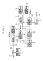
- Fig. 1 is a block diagram of the decoder, to which the image motion detection circuit of the present invention is applied, for decoding in the receiver the television transmission signal without the interframe aliased portion in the lower frequency region, as shown in JP-A-172876/87;
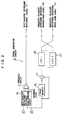
- Fig. 2 is a block diagrmam of the signal generation circuit for generating the three signals to be received by the image motion detection circuit of the present invention; and
- Fig. 3 is a block diagram showing the image motion detection circuit embodying the present invention.
- Referring to Fig. 1, the decoder arrangement includes a signal/sync detection circuit 1 which receives the transmission signal (interframe subsampling frequency: 16 MHz) without the interframe aliased portion in the lower frequency region supplied to a
signal input terminal 12 and produces a synchronizing signal used for the synchronous control of the decoder. Shown by S1 is a switch for subsample shifting, and it inserts a motion-compensated 1-frame delayed signal provided by aframe memory 2 and motion compensation circuit 3 into the transmission signal received on theinput terminal 12 to produce an interframe interpolated signal with a 32 MHz sampling frequency (on the line indicated byin the figure).
- The interframe interpolated signal from the switch S1 is entered to one input of a
signal generation circuit 4, to anintrafield interpolation circuit 5 by way of a switch S2 which operates in unison with the switch S1, and to one input of amixer 6. Thesignal generation circuit 4 has another input receiving the transmission signal from theinput terminal 12, and it produces three signals, i.e., the next-adjacent interframe difference signal (a), immediate-adjacent interframe difference narrow-band signal (b) and immediate-adjacent interframe difference broad-band signal (c) as will be described later, necessary for themotion detection circuit 30 to produce the motion signal. - The switch S2 extracts the signal only at the sampling point corresponding to the current field from the signal from the switch S1, the
intrafield interpolation circuit 5 implements intrafield interpolation for the extracted signal, and themixer 6 receives the resulting signal. Themixer 6 intermingles the motion picture system signal from theintrafield interpolation circuit 5 and the still picture system signal from the switch S1 depending on the amount of movement indicated by the output signal from themotion detection circuit 30. - An interfield interpolation circuit 9 operates to interpolate the 1-field delayed signal provided by a
field memory 7 andmotion compensation circuit 8 into the output signal from themixer 6, and the resulting interfield interpolated signal is fed to one input of a frequency converter/mixer 10. The frequency converter/mixer 10 has another input receiving a 32-MHz sampling signal from themixer 6, and thecircuit 10 converts its frequency to 48 MHz. The 48-MHz sampling signal is intermingled with the signal from the interfield interpolation circuit 9 depending on the amount of movement indicated by the output signal from themotion detection circuit 30, and the mixed signal is fed to a TCI (Time-Compressed Integration) decoder 11, by which the signal is transformed into an intended television signal and it is delivered to the output terminal. - Next, the arrangement and operation of the
signal generation circuit 4 will be described with reference to Fig. 2. In the figure, indicated by 14 is a next-adjacent interframe difference signal detection circuit, with its two input terminals receiving the signals on linesand shown in Fig. 1. Indicated by 15 is a threshold circuit which validates the output signal from the next-adjacent interframe difference
signal detection circuit 14 at a certain reference level to provide a next-adjacent interframe difference signal (a) at its output. - Indicated by 16 is frame memory and 17 is a subtracter. The
frame memory 16 receives the signal on linein Fig. 1 (the transmission signal with 16-MHz sampling frequency) and the
subtracter 17 produces the immediate-adjacent interframe difference signal. The signal is fed through a first low-pass filter 18 with a wide pass band (e.g., -6 dB at 8 MHz) to become an immediate-adjacent interframe difference broad-band signal (c), and it is fed through a second low-pass filter 19 with a narrow pass band connected in cascade with the first low-pass filter 18 to become an immediate-adjacent interframe difference narrow-band signal (b). Namely, the immediate-adjacent interframe difference narrow-band signal (b) passing through the cascade connection of the first and second low-pass filters does not include the aliased porton between frames and is not responsive above 4 MHz, in contrast to the immediate-adjacent interframe difference broad-band signal (c) which includes the aliased portion between frames and is responsive even above 4 MHz. - Next, the image motion detection apparatus according to the present invention will be described with reference to Fig. 3. The
motion detection circuit 30 consists of aframe memory 31, amotion compensation circuit 32, a maximum-value selection circuit 33 having two input terminals, a maximum-value selection circuit 34 having two input terminals, and a minimum-value selection circuit 35 having two input terminals. Thecircuit 30 has threeinput terminals output terminal 30d which is led out of the minimum-value selection circuit 35. Theinput terminals signal generation circuit 4. The next-adjacent interframe difference signal (a) on theinput terminal 30a is delivered to the input terminal of theframe memory 31 and one input terminal of the maximum-value selection circuit 33, the immediate-adjacent interframe difference narrow-band signal (b) on theinput terminal 30b is delivered to one input terminal of the maximum-value selection circuit 34, and the immediate-adjacent interframe difference broad-band signal (c) is delivered to one input terminal of the minimum-value selection circuit 35. Theframe memory 31,motion compensation circuit 32, maximum-value selection circuits value selection circuit 35 are in a cascade connection, with their other input terminals being connected to receive the outputs of the respective preceding circuits. - Next, the operation of the image
motion detection circuit 30 arranged as described above will be explained. The next-adjacent interframe difference signal (a) is received by theframe memory 31 and further modified by themotion compensation circuit 32. - The current next-adjacent interframe difference signal (a2) and the modified next-adjacent interframe difference signal (a1) preceding by one frame are supplied to the maximum-
value selection circuit 33, which selects the maximum-value between the signals (a1) and (a2). The reason for this scheme is that the next-adjacent interframe difference signal is detected only in every second sample of the picture signal in the MUSE transmission system including the aliased portion in the lower frequency region and in other MUSE transmission system as well. - Subsequently, the next-adjacent interframe difference signal (a′) selected by the maximum-
value selection circuit 33 and the immediate-adjacent interframe narrow-band signal (b) are supplied to the maximum-value selection circuit 34 which takes the maximum-value of the two signals, so that the next-adjacent interframe signal (a′) is selected for an area where a small object has moved, while the immediate-adjacent interframe difference narrow-band signal (b) is selected for an area where a large object has moved. Furthermore, the signal selected by the maximum-value selection circuit 34 and the immediate-adjacent interframe difference broad-band signal (c) are supplied to the minimum-value selection circuit 35, which selects the minimum-value between the two signals and delivers it as a motion signal to theoutput terminal 30d. Since the immediate-adjacent interframe difference broad-band signal (c) includes the aliased portion, it is needed by areas where small objects have moved. - The immediate-adjacent interframe difference broad-band signal (c) has a certain value due to the aliased portion in response to the movement of a relatively large object in the image. The minimum-
value selection circuit 35 selects the immediate-adjacent interframe difference broad-band signal (c) only for necessary areas and it inhibits the signal for unnecessary areas. When an unstable next-adjacent interframe difference signal is generated, the minimum-value selection circuit 35 inhibits the signal, whereby a stable motion signal is produced. The immediate-adjacent interframe narrow-band signal (b) is a signal which is stable in the band below 4 MHz for example. - The signal resulting from the maximum-value selection for the next-adjacent interframe difference signal and immediate-adjacent interframe difference narrow-band signal reveals generally a moving area greater than the actual moving area on the picture because they are natives of individual low-pass filters. Accordingly, by selecting the minimum-value in the output signal from the maximum-
value selection circuit 34 and the immediate-adjacent interframe difference broad-band signal by means of the minimum-value selection circuit 35, a motion signal indicating the moving area properly can be produced. - The immediate-adjacent interframe difference broad-band signal (c) is a signal which includes the aliased portion, and therefore it may create a motion signal even for a stationary area in practice. However, when as a special case an image of vertical stripe moves horizontally to coincide with the vertical stripe in the second frame, the next-adjacent interframe difference signal (a) is not produced and the immediate-adjacent interframe difference narrow-band signal (b) having a higher frequency component of the motion signal has its signal level lowered by the low-pass filter, resulting unfavorably in a smaller chance of motion signal generation. In such a case, the immediate-adjacent interframe difference broad-band signal (c), which creates the motion signal at a certain signal level, is used as a motion signal by making smaller the moving area attributable to the immediate-adjacent interframe difference narrow-band signal and next-adjacent interframe difference signal. Although this operation is opposite to the selection of motion signal described above, the signals prescribe each other for certain kinds of pictures to thereby produce a more perfect motion signal.
- When the maximum- or minimum-value selection circuit is substituted by the conventional switching circuit as described in JP-A-172876/87, the circuit may possibly make on-off operations at every second pixel repeatedly in response to signal levels around the threshold level. Since the threshold level is dependent on the kind of picture, it becomes necessary to alter the threshold level for each different picture. In practice, pictures generally have correlations and the on-off operation at every second pixel does not occur frequency; rather the threshold control will cause the aliased portion to appear at every second pixel in a picture. This is an adverse side effect of the switching circuit, and the use of the maximum- or minimum-value selection circuit as in the present invention can reduce the occurrence of this phenomenon significantly. The reason is that the on-off circuit has its threshold level dependent on the nature of picture and the circuit behaves 1-bit control, whereas the maximum- or minimum-value selection circuit behaves more smooth two or more bit control.
- In detecting a moving area of picture in the receiver of multiple subsampling transmission system without including the interframe aliased portion in the lower frequency region, application of the method and apparatus of the present invention performs correct moving area detection which could not be achieved in the past and provides a significant improvement in the picture quality.
- The image motion detection apparatus of the present invention using the maximum-value selection circuit and minimum-value selection circuit is not confined to the arrangement shown in Fig. 3. The present invention features the extraction of a maximum-value or minimum-value as a motion signal by combining appropriately the next-adjacent interframe difference signal, immediate-adjacent interframe difference narrow-band signal and immediate-adjacent interframe difference broad-band signal by use of the maximum-value selection circuit and minimum-value selection circuit. For the next-adjacent interframe difference signal, immediate-adjacent interframe difference narrow-band signal and immediate-adjacent interframe difference broad-band signal, signals produced by modifying these signals can also be used depending on each requirement. The
motion compensation circuit 32 may be located in advance of theframe memory 31.
Claims (5)
producing three signals including a next-adjacent interframe difference signal, an immediate-adjacent interframe difference narrow-band signal without the interframe aliased portion and an immediate-adjacent interframe difference broad-band signal with the interframe aliased portion;
taking a maximum-value between prescribed two signals among said next-adjacent interframe difference signal or a signal related thereto, said immediate-adjacent interframe difference narrow-band signal or a signal related thereto and said immediate-adjacent interframe difference broad-band signal or a signal related thereto; and
taking a minimum-value between a resulting maximum-value signal and a remaining signal other than said two signals so that a resulting minimum-value signal is validated as a motion signal which indicates the motion of image.
a first maximum-value selection circuit (34) which receives said next-adjacent interframe difference signal or the related signal and said immediate-adjacent interframe difference narrow-band signal or the related signal to select a maximum-value between said input signals; and
a minimum-value selection circuit (35) which receives said immediate-adjacent interframe difference broad-band signal and the output signal from said maximum-value selection circuit (34) to select a minimum-value between said input signals.
Applications Claiming Priority (2)
| Application Number | Priority Date | Filing Date | Title |
|---|---|---|---|
| JP61230126A JPS6386990A (en) | 1986-09-30 | 1986-09-30 | Move detection method |
| JP230126/86 | 1986-09-30 |
Publications (3)
| Publication Number | Publication Date |
|---|---|
| EP0263375A2 true EP0263375A2 (en) | 1988-04-13 |
| EP0263375A3 EP0263375A3 (en) | 1990-04-11 |
| EP0263375B1 EP0263375B1 (en) | 1994-07-13 |
Family
ID=16902977
Family Applications (1)
| Application Number | Title | Priority Date | Filing Date |
|---|---|---|---|
| EP19870114034 Expired - Lifetime EP0263375B1 (en) | 1986-09-30 | 1987-09-25 | A method and apparatus for detecting the motion of image in a television signal |
Country Status (7)
| Country | Link |
|---|---|
| US (1) | US4760446A (en) |
| EP (1) | EP0263375B1 (en) |
| JP (1) | JPS6386990A (en) |
| KR (1) | KR950002664B1 (en) |
| CN (1) | CN1011466B (en) |
| CA (1) | CA1274905A (en) |
| DE (1) | DE3750207T2 (en) |
Cited By (5)
| Publication number | Priority date | Publication date | Assignee | Title |
|---|---|---|---|---|
| EP0337496A2 (en) * | 1988-04-15 | 1989-10-18 | Sanyo Electric Co., Ltd. | Apparatus for demodulating subnyquist sampled video signal and demodulating method therefor |
| EP0371677A2 (en) * | 1988-11-22 | 1990-06-06 | Matsushita Electric Industrial Co., Ltd. | Image signal processing apparatus |
| GB2241409A (en) * | 1989-12-22 | 1991-08-28 | Samsung Electronics Co Ltd | Recording colour video signals |
| EP0540347A2 (en) * | 1991-10-30 | 1993-05-05 | Mitsubishi Denki Kabushiki Kaisha | Motion detection circuit for high definition television picture signal based on the muse system |
| GB2343317A (en) * | 1998-10-26 | 2000-05-03 | Sony Uk Ltd | Video motion detection |
Families Citing this family (21)
| Publication number | Priority date | Publication date | Assignee | Title |
|---|---|---|---|---|
| JPS59171387A (en) * | 1983-03-18 | 1984-09-27 | Hitachi Ltd | Method for constituting television signal |
| JPH0191586A (en) * | 1987-10-02 | 1989-04-11 | Nippon Hoso Kyokai <Nhk> | Moving detection circuit |
| US4868650A (en) * | 1988-03-07 | 1989-09-19 | Rca Licensing Corporation | Circuitry for expanding the effect of a video control signal in multiple dimensions |
| US4845557A (en) * | 1988-05-02 | 1989-07-04 | Dubner Computer Systems, Inc. | Field motion suppression in interlaced video displays |
| US4953032A (en) * | 1988-11-30 | 1990-08-28 | Hitachi, Ltd. | Motion signal generating circuit for use in a television receiver |
| US5150210A (en) * | 1988-12-26 | 1992-09-22 | Canon Kabushiki Kaisha | Image signal restoring apparatus |
| JP2576612B2 (en) * | 1988-12-28 | 1997-01-29 | 日本ビクター株式会社 | Signal converter |
| US4891699A (en) * | 1989-02-23 | 1990-01-02 | Matsushita Electric Industrial Co., Ltd. | Receiving system for band-compression image signal |
| US5027201A (en) * | 1989-12-21 | 1991-06-25 | Rca Licensing Corporation | Motion detection apparatus as for an interlace to non-interlace scan converter |
| US5191413A (en) * | 1990-11-01 | 1993-03-02 | International Business Machines | System and method for eliminating interlace motion artifacts in captured digital video data |
| KR950008710B1 (en) * | 1990-12-26 | 1995-08-04 | 삼성전자주식회사 | Field interval insert apparatus |
| JPH05174148A (en) * | 1991-12-26 | 1993-07-13 | Sony Corp | Motion detecting circuit |
| JP3315766B2 (en) * | 1992-09-07 | 2002-08-19 | 富士通株式会社 | Image data encoding method, image data encoding device using the method, image data restoring method, image data restoring device using the method, scene change detecting method, scene change detecting device using the method, scene change recording Device and image data scene change recording / reproducing device |
| US6904174B1 (en) | 1998-12-11 | 2005-06-07 | Intel Corporation | Simplified predictive video encoder |
| US7263127B1 (en) | 1998-04-02 | 2007-08-28 | Intel Corporation | Method and apparatus for simplifying frame-based motion estimation |
| US7046734B2 (en) * | 1998-04-02 | 2006-05-16 | Intel Corporation | Method and apparatus for performing real-time data encoding |
| US8780997B2 (en) | 2005-11-18 | 2014-07-15 | Apple Inc. | Regulation of decode-side processing based on perceptual masking |
| US8295343B2 (en) * | 2005-11-18 | 2012-10-23 | Apple Inc. | Video bit rate control method |
| US20070116117A1 (en) * | 2005-11-18 | 2007-05-24 | Apple Computer, Inc. | Controlling buffer states in video compression coding to enable editing and distributed encoding |
| US8233535B2 (en) | 2005-11-18 | 2012-07-31 | Apple Inc. | Region-based processing of predicted pixels |
| US8031777B2 (en) | 2005-11-18 | 2011-10-04 | Apple Inc. | Multipass video encoding and rate control using subsampling of frames |
Citations (2)
| Publication number | Priority date | Publication date | Assignee | Title |
|---|---|---|---|---|
| EP0132832A2 (en) * | 1983-07-25 | 1985-02-13 | Hitachi, Ltd. | Circuit for detecting picture motion in interlaced television signal |
| JPS60217778A (en) * | 1984-04-13 | 1985-10-31 | Hitachi Ltd | High definition television receiver |
Family Cites Families (5)
| Publication number | Priority date | Publication date | Assignee | Title |
|---|---|---|---|---|
| GB2055495B (en) * | 1979-08-01 | 1983-07-06 | British Broadcasting Corp | Movement detector for television signals |
| US4337481A (en) * | 1980-06-10 | 1982-06-29 | Peter Mick | Motion and intrusion detecting system |
| US4482970A (en) * | 1981-11-06 | 1984-11-13 | Grumman Aerospace Corporation | Boolean filtering method and apparatus |
| US4663665A (en) * | 1985-01-07 | 1987-05-05 | Nippon Hoso Kyokai | TV system conversion apparatus |
| JPS61264889A (en) * | 1985-05-20 | 1986-11-22 | Nippon Hoso Kyokai <Nhk> | Transmission system for multiple subsample |
-
1986
- 1986-09-30 JP JP61230126A patent/JPS6386990A/en active Granted
-
1987
- 1987-09-25 DE DE19873750207 patent/DE3750207T2/en not_active Expired - Fee Related
- 1987-09-25 EP EP19870114034 patent/EP0263375B1/en not_active Expired - Lifetime
- 1987-09-29 CA CA000548129A patent/CA1274905A/en not_active Expired - Fee Related
- 1987-09-29 KR KR1019870010826A patent/KR950002664B1/en not_active IP Right Cessation
- 1987-09-29 US US07/102,435 patent/US4760446A/en not_active Expired - Fee Related
- 1987-09-30 CN CN87106645A patent/CN1011466B/en not_active Expired
Patent Citations (2)
| Publication number | Priority date | Publication date | Assignee | Title |
|---|---|---|---|---|
| EP0132832A2 (en) * | 1983-07-25 | 1985-02-13 | Hitachi, Ltd. | Circuit for detecting picture motion in interlaced television signal |
| JPS60217778A (en) * | 1984-04-13 | 1985-10-31 | Hitachi Ltd | High definition television receiver |
Non-Patent Citations (2)
| Title |
|---|
| NHK LABORATORIES NOTE, no. 304, September 1984, pages 1-12, NHK, Tokyo, JP; Y. NINOMIYA et al.: "A single channel HDTV broadcast system - the muse" * |
| PATENT ABSTRACTS OF JAPAN, vol. 10, no. 69 (E-389)[2126], 18th March 1986; & JP-A-60 217 778 (HITACHI SEISAKUSHO K.K.) 31-10-1985 * |
Cited By (11)
| Publication number | Priority date | Publication date | Assignee | Title |
|---|---|---|---|---|
| EP0337496A2 (en) * | 1988-04-15 | 1989-10-18 | Sanyo Electric Co., Ltd. | Apparatus for demodulating subnyquist sampled video signal and demodulating method therefor |
| EP0337496A3 (en) * | 1988-04-15 | 1992-06-10 | Sanyo Electric Co., Ltd. | Apparatus for demodulating subnyquist sampled video signal and demodulating method therefor |
| EP0371677A2 (en) * | 1988-11-22 | 1990-06-06 | Matsushita Electric Industrial Co., Ltd. | Image signal processing apparatus |
| EP0371677A3 (en) * | 1988-11-22 | 1991-09-25 | Matsushita Electric Industrial Co., Ltd. | Image signal processing apparatus |
| GB2241409A (en) * | 1989-12-22 | 1991-08-28 | Samsung Electronics Co Ltd | Recording colour video signals |
| GB2241409B (en) * | 1989-12-22 | 1994-08-31 | Samsung Electronics Co Ltd | Method and circuit for enhancing image quality of a video tape recorder |
| EP0540347A2 (en) * | 1991-10-30 | 1993-05-05 | Mitsubishi Denki Kabushiki Kaisha | Motion detection circuit for high definition television picture signal based on the muse system |
| EP0540347A3 (en) * | 1991-10-30 | 1994-06-08 | Mitsubishi Electric Corp | Motion detection circuit for high definition television picture signal based on the muse system |
| US5497203A (en) * | 1991-10-30 | 1996-03-05 | Mitsubishi Denki Kabushiki Kaisha | Motion detection circuit for high definition television based on muse |
| GB2343317A (en) * | 1998-10-26 | 2000-05-03 | Sony Uk Ltd | Video motion detection |
| GB2343317B (en) * | 1998-10-26 | 2003-02-26 | Sony Uk Ltd | Video motion detection |
Also Published As
| Publication number | Publication date |
|---|---|
| KR880004706A (en) | 1988-06-07 |
| EP0263375A3 (en) | 1990-04-11 |
| CN1011466B (en) | 1991-01-30 |
| CA1274905A (en) | 1990-10-02 |
| EP0263375B1 (en) | 1994-07-13 |
| US4760446A (en) | 1988-07-26 |
| KR950002664B1 (en) | 1995-03-24 |
| JPS6386990A (en) | 1988-04-18 |
| DE3750207D1 (en) | 1994-08-18 |
| DE3750207T2 (en) | 1995-01-26 |
| CN87106645A (en) | 1988-04-13 |
| JPH0520952B2 (en) | 1993-03-22 |
Similar Documents
| Publication | Publication Date | Title |
|---|---|---|
| US4760446A (en) | Method and apparatus for detecting the motion of image in a television signal | |
| US5065243A (en) | Multi-screen high-definition television receiver | |
| US5144427A (en) | Television receiver decoder apparatus for bandwidth-compressed high definition television signal | |
| EP0371677B1 (en) | Image signal processing apparatus | |
| US5083203A (en) | Control signal spreader | |
| US4851904A (en) | Motion detecting circuit for digital video signal | |
| US6191824B1 (en) | Video signal processing apparatus | |
| US5128750A (en) | Television signal converter for converting a high definition television signal into a television signal for display by a standard television receiver | |
| CA2203735A1 (en) | Up-converter and scanning line conversion method | |
| US5376972A (en) | Video signal transmission/reception using high pass filters for motion detection | |
| JPH0569350B2 (en) | ||
| JP2517652B2 (en) | Band-compressed television signal receiver | |
| JP2808461B2 (en) | Television signal receiver | |
| JPS62172876A (en) | Motion detecting system for multiplex subsample transmission signal | |
| JP2720639B2 (en) | High Definition Television Receiver | |
| JP2517651B2 (en) | Band-compressed television signal receiver | |
| JP2625693B2 (en) | Transmission method of television signal | |
| JPH0246071A (en) | Television receiver | |
| JPH0294891A (en) | Movement detection circuit | |
| JPH09172620A (en) | Interpolation device and interpolation method for compressed high resolution video signal | |
| JPH05347750A (en) | Muse decoder | |
| JPH05199546A (en) | Line sequential color signal simultaneous circuit | |
| JPH02261272A (en) | High definition television receiver | |
| JPH07143457A (en) | Memory control circuit for muse decoder | |
| JPH0463091A (en) | Reception equipment for band compression television signal |
Legal Events
| Date | Code | Title | Description |
|---|---|---|---|
| PUAI | Public reference made under article 153(3) epc to a published international application that has entered the european phase |
Free format text: ORIGINAL CODE: 0009012 |
|
| AK | Designated contracting states |
Kind code of ref document: A2 Designated state(s): DE FR GB IT NL |
|
| PUAL | Search report despatched |
Free format text: ORIGINAL CODE: 0009013 |
|
| AK | Designated contracting states |
Kind code of ref document: A3 Designated state(s): DE FR GB IT NL |
|
| 17P | Request for examination filed |
Effective date: 19900907 |
|
| 17Q | First examination report despatched |
Effective date: 19920602 |
|
| GRAA | (expected) grant |
Free format text: ORIGINAL CODE: 0009210 |
|
| AK | Designated contracting states |
Kind code of ref document: B1 Designated state(s): DE FR GB IT NL |
|
| ITF | It: translation for a ep patent filed |
Owner name: JACOBACCI CASETTA & PERANI S.P.A. |
|
| ET | Fr: translation filed | ||
| REF | Corresponds to: |
Ref document number: 3750207 Country of ref document: DE Date of ref document: 19940818 |
|
| PLBE | No opposition filed within time limit |
Free format text: ORIGINAL CODE: 0009261 |
|
| STAA | Information on the status of an ep patent application or granted ep patent |
Free format text: STATUS: NO OPPOSITION FILED WITHIN TIME LIMIT |
|
| 26N | No opposition filed | ||
| PGFP | Annual fee paid to national office [announced via postgrant information from national office to epo] |
Ref country code: GB Payment date: 19980918 Year of fee payment: 12 |
|
| PGFP | Annual fee paid to national office [announced via postgrant information from national office to epo] |
Ref country code: FR Payment date: 19990909 Year of fee payment: 13 |
|
| PG25 | Lapsed in a contracting state [announced via postgrant information from national office to epo] |
Ref country code: GB Free format text: LAPSE BECAUSE OF NON-PAYMENT OF DUE FEES Effective date: 19990925 |
|
| PGFP | Annual fee paid to national office [announced via postgrant information from national office to epo] |
Ref country code: DE Payment date: 19990927 Year of fee payment: 13 |
|
| PGFP | Annual fee paid to national office [announced via postgrant information from national office to epo] |
Ref country code: NL Payment date: 19990930 Year of fee payment: 13 |
|
| GBPC | Gb: european patent ceased through non-payment of renewal fee |
Effective date: 19990925 |
|
| PG25 | Lapsed in a contracting state [announced via postgrant information from national office to epo] |
Ref country code: NL Free format text: LAPSE BECAUSE OF NON-PAYMENT OF DUE FEES Effective date: 20010401 |
|
| PG25 | Lapsed in a contracting state [announced via postgrant information from national office to epo] |
Ref country code: FR Free format text: LAPSE BECAUSE OF NON-PAYMENT OF DUE FEES Effective date: 20010531 |
|
| NLV4 | Nl: lapsed or anulled due to non-payment of the annual fee |
Effective date: 20010401 |
|
| PG25 | Lapsed in a contracting state [announced via postgrant information from national office to epo] |
Ref country code: DE Free format text: LAPSE BECAUSE OF NON-PAYMENT OF DUE FEES Effective date: 20010601 |
|
| REG | Reference to a national code |
Ref country code: FR Ref legal event code: ST |
|
| PG25 | Lapsed in a contracting state [announced via postgrant information from national office to epo] |
Ref country code: IT Free format text: LAPSE BECAUSE OF NON-PAYMENT OF DUE FEES;WARNING: LAPSES OF ITALIAN PATENTS WITH EFFECTIVE DATE BEFORE 2007 MAY HAVE OCCURRED AT ANY TIME BEFORE 2007. THE CORRECT EFFECTIVE DATE MAY BE DIFFERENT FROM THE ONE RECORDED. Effective date: 20050925 |