EP0267632A1 - Roller Bearing - Google Patents
Roller Bearing Download PDFInfo
- Publication number
- EP0267632A1 EP0267632A1 EP87200682A EP87200682A EP0267632A1 EP 0267632 A1 EP0267632 A1 EP 0267632A1 EP 87200682 A EP87200682 A EP 87200682A EP 87200682 A EP87200682 A EP 87200682A EP 0267632 A1 EP0267632 A1 EP 0267632A1
- Authority
- EP
- European Patent Office
- Prior art keywords
- seal
- annular
- race
- annular space
- rolling bearing
- Prior art date
- Legal status (The legal status is an assumption and is not a legal conclusion. Google has not performed a legal analysis and makes no representation as to the accuracy of the status listed.)
- Granted
Links
Images
Classifications
-
- F—MECHANICAL ENGINEERING; LIGHTING; HEATING; WEAPONS; BLASTING
- F16—ENGINEERING ELEMENTS AND UNITS; GENERAL MEASURES FOR PRODUCING AND MAINTAINING EFFECTIVE FUNCTIONING OF MACHINES OR INSTALLATIONS; THERMAL INSULATION IN GENERAL
- F16C—SHAFTS; FLEXIBLE SHAFTS; ELEMENTS OR CRANKSHAFT MECHANISMS; ROTARY BODIES OTHER THAN GEARING ELEMENTS; BEARINGS
- F16C33/00—Parts of bearings; Special methods for making bearings or parts thereof
- F16C33/72—Sealings
- F16C33/76—Sealings of ball or roller bearings
- F16C33/762—Sealings of ball or roller bearings by means of a fluid
- F16C33/763—Sealings of ball or roller bearings by means of a fluid retained in the sealing gap
- F16C33/765—Sealings of ball or roller bearings by means of a fluid retained in the sealing gap by a magnetic field
-
- F—MECHANICAL ENGINEERING; LIGHTING; HEATING; WEAPONS; BLASTING
- F16—ENGINEERING ELEMENTS AND UNITS; GENERAL MEASURES FOR PRODUCING AND MAINTAINING EFFECTIVE FUNCTIONING OF MACHINES OR INSTALLATIONS; THERMAL INSULATION IN GENERAL
- F16C—SHAFTS; FLEXIBLE SHAFTS; ELEMENTS OR CRANKSHAFT MECHANISMS; ROTARY BODIES OTHER THAN GEARING ELEMENTS; BEARINGS
- F16C33/00—Parts of bearings; Special methods for making bearings or parts thereof
- F16C33/30—Parts of ball or roller bearings
- F16C33/66—Special parts or details in view of lubrication
- F16C33/6637—Special parts or details in view of lubrication with liquid lubricant
- F16C33/664—Retaining the liquid in or near the bearing
- F16C33/6644—Retaining the liquid in or near the bearing by a magnetic field acting on a magnetic liquid
-
- F—MECHANICAL ENGINEERING; LIGHTING; HEATING; WEAPONS; BLASTING
- F16—ENGINEERING ELEMENTS AND UNITS; GENERAL MEASURES FOR PRODUCING AND MAINTAINING EFFECTIVE FUNCTIONING OF MACHINES OR INSTALLATIONS; THERMAL INSULATION IN GENERAL
- F16C—SHAFTS; FLEXIBLE SHAFTS; ELEMENTS OR CRANKSHAFT MECHANISMS; ROTARY BODIES OTHER THAN GEARING ELEMENTS; BEARINGS
- F16C33/00—Parts of bearings; Special methods for making bearings or parts thereof
- F16C33/72—Sealings
- F16C33/76—Sealings of ball or roller bearings
- F16C33/78—Sealings of ball or roller bearings with a diaphragm, disc, or ring, with or without resilient members
- F16C33/7896—Sealings of ball or roller bearings with a diaphragm, disc, or ring, with or without resilient members with two or more discrete sealings arranged in series
-
- F—MECHANICAL ENGINEERING; LIGHTING; HEATING; WEAPONS; BLASTING
- F16—ENGINEERING ELEMENTS AND UNITS; GENERAL MEASURES FOR PRODUCING AND MAINTAINING EFFECTIVE FUNCTIONING OF MACHINES OR INSTALLATIONS; THERMAL INSULATION IN GENERAL
- F16J—PISTONS; CYLINDERS; SEALINGS
- F16J15/00—Sealings
- F16J15/16—Sealings between relatively-moving surfaces
- F16J15/40—Sealings between relatively-moving surfaces by means of fluid
- F16J15/43—Sealings between relatively-moving surfaces by means of fluid kept in sealing position by magnetic force
-
- F—MECHANICAL ENGINEERING; LIGHTING; HEATING; WEAPONS; BLASTING
- F16—ENGINEERING ELEMENTS AND UNITS; GENERAL MEASURES FOR PRODUCING AND MAINTAINING EFFECTIVE FUNCTIONING OF MACHINES OR INSTALLATIONS; THERMAL INSULATION IN GENERAL
- F16C—SHAFTS; FLEXIBLE SHAFTS; ELEMENTS OR CRANKSHAFT MECHANISMS; ROTARY BODIES OTHER THAN GEARING ELEMENTS; BEARINGS
- F16C19/00—Bearings with rolling contact, for exclusively rotary movement
- F16C19/02—Bearings with rolling contact, for exclusively rotary movement with bearing balls essentially of the same size in one or more circular rows
- F16C19/04—Bearings with rolling contact, for exclusively rotary movement with bearing balls essentially of the same size in one or more circular rows for radial load mainly
- F16C19/06—Bearings with rolling contact, for exclusively rotary movement with bearing balls essentially of the same size in one or more circular rows for radial load mainly with a single row or balls
-
- F—MECHANICAL ENGINEERING; LIGHTING; HEATING; WEAPONS; BLASTING
- F16—ENGINEERING ELEMENTS AND UNITS; GENERAL MEASURES FOR PRODUCING AND MAINTAINING EFFECTIVE FUNCTIONING OF MACHINES OR INSTALLATIONS; THERMAL INSULATION IN GENERAL
- F16C—SHAFTS; FLEXIBLE SHAFTS; ELEMENTS OR CRANKSHAFT MECHANISMS; ROTARY BODIES OTHER THAN GEARING ELEMENTS; BEARINGS
- F16C2300/00—Application independent of particular apparatuses
- F16C2300/02—General use or purpose, i.e. no use, purpose, special adaptation or modification indicated or a wide variety of uses mentioned
Definitions
- the invention concerns a rolling bearing comprising at least one outer race and at least one inner race situated coaxially therein, and at least one row of rolling members situated in the annular space between these races, and seals for sealing the annular space between the races off from the surroundings on either side of the rolling members, to prevent a lubricant present in this space from escaping to the outside and, on the other hand, to prevent any foreign matter from penetrating into the annular space from the outside, at least one of which seals is generally annular and comprises at least one sealing lip which is in c om- munication with one of the races and rests springily against the other race.
- Such a rolling bearing is generally known.
- the object of the invention is to procure a rolling bearing of the type mentioned wherein this phenomenon does not occur.
- the annular seal has an end portion that lies behind the inwardly directed side of the sealing lip .. at a short distance from the said other race, and the slot-shaped annular space thus formed between the seal and the said race contains a quantity of magnetic fluid, where means forming a magnetic field are present, whereby such fluid is held within the slot-shaped annular space.
- the means for formation of a magnetic field are advantageously formed by an annular magnet of which one pole is situated near the outer peripheral area and the other pole near the inner peripheral area of the ring.
- annular magnet is preferably formed by the annular seal, the sealing lip being attached to the said ring.
- the bearing may be further improved in that a plurality of slot-shaped annular spaces, situated one behind the other in axial direction, are present, which spaces are separated from one another by open annular spaces having a greater depth.
- the annular space between the races in addition to the lubricant, may advantageously contain an inert gas instead of air, whereby oxidation of the lubricant and components of the bearing is prevented.
- a magnetic fluid is known per se and consists of a colloidal suspension of extremely small particles, in the order of magnitude of 7-10 pm, of a material having paramagnetic properties, usually magnetized, in a fluid consisting mostly of a hydrocarbon, these particles being clad with a thin layer of a material that prevents flocculation of the particles.
- the particles normally move constantly in the fluid as a result of thermal agitation and Brownian movement, but when such a magnetic fluid is located in a magnetic field the particles orient themselves in essentially one direction, whereby the fluid acts like soft iron.
- the rolling bearing comprises an outer race 1 and an inner race 2 situated coaxially therein, and a row of rolling members 3 situated in the annular space between these races, which are kept apart by a cage 4.
- the annular space between the races 1 and 2 is sealed off from the surroundings by the sealing rings 5 which are designed as magnets with the north and south poles indicated.
- the sealing rings 5 In the end portion of the sealing ring 5 directed toward the inner race 2 is provided a plurality of grooves, so that between these grooves are formed ridges 7 which lie at a short distance from the inner race 2.
- the slot-shaped annular spaces thus formed between the sealing ring 5 and the inner race 2 contain a quantity of magnetic fluid 8, which fluid is held in these slot-shaped spaces by the magnetic field formed by the sealing ring 5, the lines of force of said magnetic field being indicated by the arrows A.
- seal 9 having a sealing lip 9', which lip 9' rests springily against the outer race 1.
- the seal 9 is preferably formed of a self-lubricating elastomeric material so that only very little friction will occur between the sealing lip 9' and the inner race 2 upon rotation of one of the races 1, 2.
Abstract
Description
- The invention concerns a rolling bearing comprising at least one outer race and at least one inner race situated coaxially therein, and at least one row of rolling members situated in the annular space between these races, and seals for sealing the annular space between the races off from the surroundings on either side of the rolling members, to prevent a lubricant present in this space from escaping to the outside and, on the other hand, to prevent any foreign matter from penetrating into the annular space from the outside, at least one of which seals is generally annular and comprises at least one sealing lip which is in com- munication with one of the races and rests springily against the other race. Such a rolling bearing is generally known.
- In rolling bearings of this type the problem arises that during rotation of an element supported by such a bearing, for example a shaft, the temperature within the bearing increases with respect to the ambient temperature, whereby the air, particularly the vapor in the lubricant, inside the bearing expands with the result that the sealing lip is pressed outward and no longer has a sealing contact with the race concerned against which the lip rests springily, so that the seal is broken and the comparatively vaporous lubricant leaks out of the bearing to the outside. Then if the bearing cools down again air may be drawn in from the outside and impurities, for example in the form of dust particles, may be carried along which may have a failure- producing effect on the bearing. This phenomenon, which is called "breathing" of the bearing, is the main cause of leakage of the lubricant from the bearing despite the seals used.
- The object of the invention is to procure a rolling bearing of the type mentioned wherein this phenomenon does not occur.
- This object is accomplished in that in the rolling bearing pursuant to the invention the annular seal has an end portion that lies behind the inwardly directed side of the sealing lip .. at a short distance from the said other race, and the slot-shaped annular space thus formed between the seal and the said race contains a quantity of magnetic fluid, where means forming a magnetic field are present, whereby such fluid is held within the slot-shaped annular space.
- In a rolling bearing designed in this way the seal obtained by the magnetic fluid withstands any difference in vapor pressure between the inner side of the bearing and the surroundings, so that the sealing lip always remains in sealing contact with the race concerned, and, on the other hand, the magnetic fluid is protected against penetration into it from the outside of impurities which may be detrimental to a good sealing effect of such fluid. By this means, therefore, leakage due to "breathing" of the bearing is no longer possible.
- The means for formation of a magnetic field are advantageously formed by an annular magnet of which one pole is situated near the outer peripheral area and the other pole near the inner peripheral area of the ring. In this connection, such annular magnet is preferably formed by the annular seal, the sealing lip being attached to the said ring.
- The bearing may be further improved in that a plurality of slot-shaped annular spaces, situated one behind the other in axial direction, are present, which spaces are separated from one another by open annular spaces having a greater depth.
- Since in a bearing pursuant to the invention a complete seal from the surroundings is obtained, where periodic exchanges of air or vapor between the surroundings and the inner side of the bearing are thus unable to occur, the annular space between the races, in addition to the lubricant, may advantageously contain an inert gas instead of air, whereby oxidation of the lubricant and components of the bearing is prevented.
- A magnetic fluid is known per se and consists of a colloidal suspension of extremely small particles, in the order of magnitude of 7-10 pm, of a material having paramagnetic properties, usually magnetized, in a fluid consisting mostly of a hydrocarbon, these particles being clad with a thin layer of a material that prevents flocculation of the particles. The particles normally move constantly in the fluid as a result of thermal agitation and Brownian movement, but when such a magnetic fluid is located in a magnetic field the particles orient themselves in essentially one direction, whereby the fluid acts like soft iron.
- It is noted further that American Patent 4043612 discloses that a magnetic lubricant may be used in a bearing design where such lubricant is placed under pressure during rotation by a pumping action obtained by means of grooves, and such lubricant, upon standstill of the bearing, is held within the bearing by means of a magnetic field.
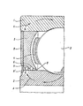
- The invention is described in detail with reference to the drawing, wherein a portion of the rolling bearing pursuant to the invention is shown in axial cross section.
- As illustrated in the drawing, the rolling bearing comprises an outer race 1 and an
inner race 2 situated coaxially therein, and a row ofrolling members 3 situated in the annular space between these races, which are kept apart by a cage 4. The annular space between theraces 1 and 2 is sealed off from the surroundings by the sealingrings 5 which are designed as magnets with the north and south poles indicated. In the end portion of thesealing ring 5 directed toward theinner race 2 is provided a plurality of grooves, so that between these grooves are formedridges 7 which lie at a short distance from theinner race 2. The slot-shaped annular spaces thus formed between thesealing ring 5 and theinner race 2 contain a quantity ofmagnetic fluid 8, which fluid is held in these slot-shaped spaces by the magnetic field formed by thesealing ring 5, the lines of force of said magnetic field being indicated by the arrows A. - To the sealing
ring 5 is attached aseal 9 having a sealing lip 9', which lip 9' rests springily against the outer race 1. Theseal 9 is preferably formed of a self-lubricating elastomeric material so that only very little friction will occur between the sealing lip 9' and theinner race 2 upon rotation of one of theraces 1, 2.
Claims (5)
Applications Claiming Priority (2)
| Application Number | Priority Date | Filing Date | Title |
|---|---|---|---|
| NL8601017 | 1986-04-21 | ||
| NL8601017A NL8601017A (en) | 1986-04-21 | 1986-04-21 | ROLLER BEARING. |
Publications (2)
| Publication Number | Publication Date |
|---|---|
| EP0267632A1 true EP0267632A1 (en) | 1988-05-18 |
| EP0267632B1 EP0267632B1 (en) | 1991-07-03 |
Family
ID=19847913
Family Applications (1)
| Application Number | Title | Priority Date | Filing Date |
|---|---|---|---|
| EP87200682A Expired - Lifetime EP0267632B1 (en) | 1986-04-21 | 1987-04-13 | Roller bearing |
Country Status (5)
| Country | Link |
|---|---|
| US (1) | US4761082A (en) |
| EP (1) | EP0267632B1 (en) |
| JP (1) | JPS62297537A (en) |
| DE (1) | DE3771174D1 (en) |
| NL (1) | NL8601017A (en) |
Cited By (6)
| Publication number | Priority date | Publication date | Assignee | Title |
|---|---|---|---|---|
| DE3719116A1 (en) * | 1986-06-10 | 1987-12-17 | Papst Motoren Gmbh & Co Kg | Arrangement for a magnetic liquid seal |
| DE3842477A1 (en) * | 1988-07-11 | 1990-01-18 | Nihon Densan Kk | MAGNETIC FLUID SEAL COMPOSITION |
| EP0357105A1 (en) * | 1988-08-02 | 1990-03-07 | SKF Industrial Trading & Development Co, B.V. | Sealing device with a magnetic liquid |
| EP0661473A1 (en) * | 1993-12-28 | 1995-07-05 | SKF Industrial Trading & Development Company, B.V. | Water repellent filter seal |
| EP2778449A4 (en) * | 2011-11-08 | 2016-01-27 | Eagle Ind Co Ltd | Sealing device using magnetic fluid |
| CN110425224A (en) * | 2019-07-19 | 2019-11-08 | 南京航空航天大学 | The bearing seal coil structures of magnetic fluid medium |
Families Citing this family (11)
| Publication number | Priority date | Publication date | Assignee | Title |
|---|---|---|---|---|
| US5238254A (en) * | 1987-07-17 | 1993-08-24 | Koyo Seiko Co., Ltd. | Ferrofluid seal apparatus |
| DE8904503U1 (en) * | 1989-04-11 | 1989-05-18 | Fag Kugelfischer Georg Schaefer Kgaa, 8720 Schweinfurt, De | |
| JP2518873Y2 (en) * | 1989-10-19 | 1996-11-27 | エヌオーケー株式会社 | Magnetic fluid sealing device |
| IL94955A0 (en) * | 1990-07-03 | 1991-06-10 | Msb Technologies Ltd | Spindle assembly |
| US6082685A (en) * | 1996-06-07 | 2000-07-04 | Sachtler Ag | Telescopic stand |
| DE19622894C1 (en) * | 1996-06-07 | 1997-08-21 | Sachtler Ag | Telescopic frame with at least one frame leg |
| US6808741B1 (en) * | 2001-10-26 | 2004-10-26 | Seagate Technology Llc | In-line, pass-by method for vapor lubrication |
| US7188840B2 (en) * | 2003-07-07 | 2007-03-13 | Zhixin Li | Magnetic fluidic seal with improved pressure capacity |
| JP2007192378A (en) * | 2006-01-23 | 2007-08-02 | Jtekt Corp | Hub unit, method of manufacturing hub unit and method of transporting hub unit |
| WO2013001329A1 (en) * | 2011-06-28 | 2013-01-03 | Aktiebolaget Skf | Sealed bearing assembly with magnet on sealing disc to attract metallic particles |
| CN112728110B (en) * | 2021-01-13 | 2021-12-28 | 清华大学 | Magnetic liquid sealing device |
Citations (1)
| Publication number | Priority date | Publication date | Assignee | Title |
|---|---|---|---|---|
| US4531846A (en) * | 1983-12-27 | 1985-07-30 | Ferrofluidics Corporation | Compact ferrofluid seal and bearing assembly |
Family Cites Families (6)
| Publication number | Priority date | Publication date | Assignee | Title |
|---|---|---|---|---|
| GB876655A (en) * | 1959-03-02 | 1961-09-06 | Georg Schafer | Improvements in and relating to anti-friction bearing seals |
| US4043612A (en) * | 1975-06-06 | 1977-08-23 | Ampex Corporation | Bearing structure |
| US4171818A (en) * | 1977-04-04 | 1979-10-23 | Ferrofluidics Corporation | Dynamic lip seal using ferrofluids as sealant/lubricant |
| US4309040A (en) * | 1980-06-03 | 1982-01-05 | Ferrofluidics Corporation | Linear seal apparatus |
| US4628384A (en) * | 1983-08-26 | 1986-12-09 | Ferrofluidics Corporation | Bearing assembly with integrated ferrofluid seal |
| JPS60205018A (en) * | 1984-03-28 | 1985-10-16 | Agency Of Ind Science & Technol | Roller bearing device of magnetic fluid seal type |
-
1986
- 1986-04-21 NL NL8601017A patent/NL8601017A/en not_active Application Discontinuation
-
1987
- 1987-04-13 EP EP87200682A patent/EP0267632B1/en not_active Expired - Lifetime
- 1987-04-13 DE DE8787200682T patent/DE3771174D1/en not_active Expired - Fee Related
- 1987-04-16 US US07/039,466 patent/US4761082A/en not_active Expired - Fee Related
- 1987-04-20 JP JP62095469A patent/JPS62297537A/en active Pending
Patent Citations (1)
| Publication number | Priority date | Publication date | Assignee | Title |
|---|---|---|---|---|
| US4531846A (en) * | 1983-12-27 | 1985-07-30 | Ferrofluidics Corporation | Compact ferrofluid seal and bearing assembly |
Cited By (10)
| Publication number | Priority date | Publication date | Assignee | Title |
|---|---|---|---|---|
| DE3719116A1 (en) * | 1986-06-10 | 1987-12-17 | Papst Motoren Gmbh & Co Kg | Arrangement for a magnetic liquid seal |
| DE3719116B4 (en) * | 1986-06-10 | 2006-05-04 | Papst Licensing Gmbh & Co. Kg | Hard disk space |
| DE3842477A1 (en) * | 1988-07-11 | 1990-01-18 | Nihon Densan Kk | MAGNETIC FLUID SEAL COMPOSITION |
| US5009436A (en) * | 1988-07-11 | 1991-04-23 | Nippon Densan Corporation | Magnetic fluid seal assembly |
| EP0357105A1 (en) * | 1988-08-02 | 1990-03-07 | SKF Industrial Trading & Development Co, B.V. | Sealing device with a magnetic liquid |
| EP0661473A1 (en) * | 1993-12-28 | 1995-07-05 | SKF Industrial Trading & Development Company, B.V. | Water repellent filter seal |
| NL9302277A (en) * | 1993-12-28 | 1995-07-17 | Skf Ind Trading & Dev | Water-repellent filter seal. |
| US5513918A (en) * | 1993-12-28 | 1996-05-07 | Skf Industrial Trading And Development Company B.V. | Roller element bearing with water repellent filter seal |
| EP2778449A4 (en) * | 2011-11-08 | 2016-01-27 | Eagle Ind Co Ltd | Sealing device using magnetic fluid |
| CN110425224A (en) * | 2019-07-19 | 2019-11-08 | 南京航空航天大学 | The bearing seal coil structures of magnetic fluid medium |
Also Published As
| Publication number | Publication date |
|---|---|
| DE3771174D1 (en) | 1991-08-08 |
| EP0267632B1 (en) | 1991-07-03 |
| NL8601017A (en) | 1987-11-16 |
| US4761082A (en) | 1988-08-02 |
| JPS62297537A (en) | 1987-12-24 |
Similar Documents
| Publication | Publication Date | Title |
|---|---|---|
| EP0267632A1 (en) | Roller Bearing | |
| US4694213A (en) | Ferrofluid seal for a stationary shaft and a rotating hub | |
| US4043616A (en) | Bearing cartridge assembly | |
| US6845986B2 (en) | Low torque seal assembly | |
| US3479840A (en) | Trunnion seal for cardan-type universal joint | |
| AU606836B2 (en) | Bearing isolator seal | |
| US4286829A (en) | Bearing for high rotational speeds | |
| US6050570A (en) | Seal with bi-modulus lip | |
| FR2557940B1 (en) | BEARING COMPRISING AN INTEGRATED SINGLE-STAGE FERROFLUID SEALING DEVICE | |
| CA2244678C (en) | Rotating sealing device | |
| US4389053A (en) | Water guard for rolling mill oil film bearing | |
| US4526381A (en) | Magnetic disc liquid supporting | |
| US4765756A (en) | Rolling bearing | |
| US4597582A (en) | Flocked fiber seal for rolling bearings | |
| EP1205694B1 (en) | Seal unit for mechanical members rotating relative to each other, in particular for foundry rollers | |
| GB2057591A (en) | Roller bearing | |
| US6290234B1 (en) | Shaft assembly having improved seal arrangement | |
| US3790178A (en) | Bearing seal | |
| US4840385A (en) | Device for sealing shaft bearings or shaft bearing housings | |
| GB819082A (en) | Packing for axles, shafts, rods, bearings and similar machine parts | |
| EP0129270A1 (en) | Sealing ring for a rolling bearing | |
| EP0306979A2 (en) | Magnetic seal assembly | |
| JPH0921397A (en) | Bearing seal device for water pump | |
| JPS60205018A (en) | Roller bearing device of magnetic fluid seal type | |
| JPH066753U (en) | Split type rotary bearing unit |
Legal Events
| Date | Code | Title | Description |
|---|---|---|---|
| PUAI | Public reference made under article 153(3) epc to a published international application that has entered the european phase |
Free format text: ORIGINAL CODE: 0009012 |
|
| AK | Designated contracting states |
Kind code of ref document: A1 Designated state(s): CH DE FR GB IT LI NL |
|
| 17P | Request for examination filed |
Effective date: 19881031 |
|
| 17Q | First examination report despatched |
Effective date: 19890814 |
|
| GRAA | (expected) grant |
Free format text: ORIGINAL CODE: 0009210 |
|
| AK | Designated contracting states |
Kind code of ref document: B1 Designated state(s): CH DE FR GB IT LI NL |
|
| ET | Fr: translation filed | ||
| REF | Corresponds to: |
Ref document number: 3771174 Country of ref document: DE Date of ref document: 19910808 |
|
| ITF | It: translation for a ep patent filed |
Owner name: STUDIO TORTA SOCIETA' SEMPLICE |
|
| PGFP | Annual fee paid to national office [announced via postgrant information from national office to epo] |
Ref country code: FR Payment date: 19920413 Year of fee payment: 6 |
|
| PGFP | Annual fee paid to national office [announced via postgrant information from national office to epo] |
Ref country code: CH Payment date: 19920415 Year of fee payment: 6 |
|
| PGFP | Annual fee paid to national office [announced via postgrant information from national office to epo] |
Ref country code: GB Payment date: 19920416 Year of fee payment: 6 Ref country code: DE Payment date: 19920416 Year of fee payment: 6 |
|
| PGFP | Annual fee paid to national office [announced via postgrant information from national office to epo] |
Ref country code: NL Payment date: 19920430 Year of fee payment: 6 |
|
| PLBE | No opposition filed within time limit |
Free format text: ORIGINAL CODE: 0009261 |
|
| STAA | Information on the status of an ep patent application or granted ep patent |
Free format text: STATUS: NO OPPOSITION FILED WITHIN TIME LIMIT |
|
| 26N | No opposition filed | ||
| PG25 | Lapsed in a contracting state [announced via postgrant information from national office to epo] |
Ref country code: GB Effective date: 19930413 |
|
| PG25 | Lapsed in a contracting state [announced via postgrant information from national office to epo] |
Ref country code: LI Effective date: 19930430 Ref country code: CH Effective date: 19930430 |
|
| PG25 | Lapsed in a contracting state [announced via postgrant information from national office to epo] |
Ref country code: NL Effective date: 19931101 |
|
| GBPC | Gb: european patent ceased through non-payment of renewal fee |
Effective date: 19930413 |
|
| NLV4 | Nl: lapsed or anulled due to non-payment of the annual fee | ||
| PG25 | Lapsed in a contracting state [announced via postgrant information from national office to epo] |
Ref country code: FR Effective date: 19931229 |
|
| REG | Reference to a national code |
Ref country code: CH Ref legal event code: PL |
|
| PG25 | Lapsed in a contracting state [announced via postgrant information from national office to epo] |
Ref country code: DE Effective date: 19940101 |
|
| REG | Reference to a national code |
Ref country code: FR Ref legal event code: ST |
|
| PG25 | Lapsed in a contracting state [announced via postgrant information from national office to epo] |
Ref country code: IT Free format text: LAPSE BECAUSE OF NON-PAYMENT OF DUE FEES;WARNING: LAPSES OF ITALIAN PATENTS WITH EFFECTIVE DATE BEFORE 2007 MAY HAVE OCCURRED AT ANY TIME BEFORE 2007. THE CORRECT EFFECTIVE DATE MAY BE DIFFERENT FROM THE ONE RECORDED. Effective date: 20050413 |