EP0268395A2 - Print head for ink jet printer - Google Patents
Print head for ink jet printer Download PDFInfo
- Publication number
- EP0268395A2 EP0268395A2 EP87309453A EP87309453A EP0268395A2 EP 0268395 A2 EP0268395 A2 EP 0268395A2 EP 87309453 A EP87309453 A EP 87309453A EP 87309453 A EP87309453 A EP 87309453A EP 0268395 A2 EP0268395 A2 EP 0268395A2
- Authority
- EP
- European Patent Office
- Prior art keywords
- print head
- transducers
- conductor
- electrode
- electrically conducting
- Prior art date
- Legal status (The legal status is an assumption and is not a legal conclusion. Google has not performed a legal analysis and makes no representation as to the accuracy of the status listed.)
- Granted
Links
Images


Classifications
-
- B—PERFORMING OPERATIONS; TRANSPORTING
- B41—PRINTING; LINING MACHINES; TYPEWRITERS; STAMPS
- B41J—TYPEWRITERS; SELECTIVE PRINTING MECHANISMS, i.e. MECHANISMS PRINTING OTHERWISE THAN FROM A FORME; CORRECTION OF TYPOGRAPHICAL ERRORS
- B41J2/00—Typewriters or selective printing mechanisms characterised by the printing or marking process for which they are designed
- B41J2/005—Typewriters or selective printing mechanisms characterised by the printing or marking process for which they are designed characterised by bringing liquid or particles selectively into contact with a printing material
- B41J2/01—Ink jet
- B41J2/135—Nozzles
- B41J2/14—Structure thereof only for on-demand ink jet heads
- B41J2/14201—Structure of print heads with piezoelectric elements
- B41J2/1429—Structure of print heads with piezoelectric elements of tubular type
-
- B—PERFORMING OPERATIONS; TRANSPORTING
- B41—PRINTING; LINING MACHINES; TYPEWRITERS; STAMPS
- B41J—TYPEWRITERS; SELECTIVE PRINTING MECHANISMS, i.e. MECHANISMS PRINTING OTHERWISE THAN FROM A FORME; CORRECTION OF TYPOGRAPHICAL ERRORS
- B41J2/00—Typewriters or selective printing mechanisms characterised by the printing or marking process for which they are designed
- B41J2/005—Typewriters or selective printing mechanisms characterised by the printing or marking process for which they are designed characterised by bringing liquid or particles selectively into contact with a printing material
- B41J2/01—Ink jet
- B41J2/135—Nozzles
- B41J2/145—Arrangement thereof
- B41J2/15—Arrangement thereof for serial printing
-
- B—PERFORMING OPERATIONS; TRANSPORTING
- B41—PRINTING; LINING MACHINES; TYPEWRITERS; STAMPS
- B41J—TYPEWRITERS; SELECTIVE PRINTING MECHANISMS, i.e. MECHANISMS PRINTING OTHERWISE THAN FROM A FORME; CORRECTION OF TYPOGRAPHICAL ERRORS
- B41J2/00—Typewriters or selective printing mechanisms characterised by the printing or marking process for which they are designed
- B41J2/005—Typewriters or selective printing mechanisms characterised by the printing or marking process for which they are designed characterised by bringing liquid or particles selectively into contact with a printing material
- B41J2/01—Ink jet
- B41J2/135—Nozzles
- B41J2/14—Structure thereof only for on-demand ink jet heads
- B41J2002/14491—Electrical connection
Definitions
- This invention relates to a print head for an ink jet printer in which ink drops are generated on demand in response to suitable electrical signals.
- the object of the present invention is to provide an improved print head for an ink jet printer.
- the present invention relates to a print head for an ink jet printer of the type which comprises a plurality of piezoelectric transducers each having at least one electrode, a housing member for holding the transducers in spaced apart positions, a conductor member including a plurality of separate electrical conductors thereon and mounted in a fixed position adjacent to the tranducers, and a connector member positioned adjacent to the transducers and the conductor member and providing an electrical connection between each electrode on the transducers and a corresponding one of the electrical conductors.
- the print head is characterised in that the connector member comprises a resilient body and a plurality of electrically conducting elements mounted on the body, and the connector member is positioned so that each electrically conducting element abuts against a respective electrode and a respective electrical conductor.
- the print head 10 illustrated in FIG 1 comprises an actuator section 12 to which liquid ink is supplied from ink supply section 14.
- Actuator section 12 provides the driving force to eject drops of liquid ink from orifices in a print element section 16.
- a fan-in section 18 provides ink channels which extend from the actuator section 12 to the print element section 16.
- the present invention is directed to the actuator section 12, and this section will be described in detail after a brief description of the other components of the print head 10.
- the ink supply section 14 comprises an ink supply means 11 which supplies a marking fluid such as liquid ink to a manifold 13.
- Manifold 13 includes a plurality of openings which connect with corresponding openings in the actuator section 12, in order to feed the liquid ink to each of a plurality of transducers in actuator section 12.
- a transducer gasket (not shown) is provided to seal all the ink paths between the ink supply section 14 and the actuator section 12 in fluid tight relation.
- the fan-in section 18 comprises a plurality of ink channels, one end of each of which is positioned to mate with a corresponding one of the transducers in actuator section 12, and this mating interface is maintained in fluid tight relation by another transducer gasket (not shown). As the ink channels extend through the fan-in section 18 toward the print element section 16, the spacing of the ink channels converges from the spacing of the transducers in actuator section 12 to the spacing of the orifices in print element section 16.
- the print element section 16 comprises an orifice plate substrate 21 in which are formed a plurality of openings in registration with the ink channels in fan-in section 18, and the interface is maintained in fluid tight relation by a further gasket member (not shown).
- An orifice plate 22 has a plurality of nozzles or orifices 23 in registration with the openings in orifice plate substrate 21.
- the orifice plate substrate 21 provides support for the fragile orifice plate 22, and the orifice plate 22 is permanently bonded to the orifice plate substrate 21.
- each of the ink channels through the fan-in section 18, the gasket member 20, and the orifice plate substrate 21 is chosen to provide a good acoustic impedance match in order to minimise reflections of the ejection pressure wave in each channel of the ink drop generator.
- the actuator section 12 comprises a plurality of piezoelectric tubes 26 which are held in position by a tube housing member 24.
- Tube housing member 24 can be a moulded plastic part, for example, and comprises a plurality of openings into which the piezoelectric tubes 26 engage with a close fit.
- the piezoelectric tubes 26 are coated, both inside and outside, with a conductive material that is resistant to corrosion by the liquid ink. Near each end of the tube 26 a gap in the form of a ring 28 is formed on the outside of the tube. No conductive material is present in each ring 28.
- the rings 28 have the effect of producing two electrodes on the tube.
- the first electrode 30 comprises the portions of conductive material formed on the inside of the tube, around the ends of the tube, and on the outside of the tube near the ends of the tube.
- the second electrode 32 comprises the portion of conductive material formed in the centre portion of the outside of the tube between the two rings 28.
- the first electrode 30 is connected to a reference potential and the second electrode 32 carries the drive signal for each of the piezoelectric tubes 26.
- the active portion of each tube 26 is the centre portion, that is, the portion between the two rings 28.
- the tube momentarily contracts and generates a pressure wave in the ink inside the tube. A portion of this pressure wave travels forward along the channel from the centre portion of the tube 26 and the forward travelling pressure wave causes the ejection of a drop of ink from the corresponding orifice 23 when the pressure wave reaches the print element section 16.
- the actuator section 12 is divided into two symmetrical halves.
- the actuator section 12 comprises a supporting frame 34 having two identical halves 36 fastened together and two identical module blocks 38 of piezoelectric tubes 26.
- Each module block 38 (FIG. 3) is made of an inexpensive, non-conductive material such as plastic with two columns each having a selected number of holes 40 through its entire length. These holes 40 are made just large enough for free insertion of the piezoelectric tubes 26.
- Two slots 42, 44 are provided on each side of each block 38 to expose the signal electrodes 32 and the reference electrodes 30 of the piezoelectric tubes 26 in the block.
- Two electrical connector members 46 are provided to connect each electrode 30, 32 to a corresponding electrical conductor 48 on a flat cable conductor 50.
- Each electrical conductor member 46 comprises a resilient body member 52 which is electrically non-conductive and which has electrically conductive rings 54 at spaced intervals on its other surface so that electrical contact is made between each one of the conductors 48 and a corresponding one of the electrodes 30 or 32 of the piezoelectric transducers 26.
- the completed actuator section 12 is fastened to the ink supply section 14 and the fan-in section 18 by suitable screws, clamps or clips.
- a flat gasket member 56 (FIG. 4) having openings corresponding to holes 40 is placed on each end of the actuator section 12.
- the control signals to produce the desired printed data are coupled to corresponding ones of conductors 48.
- the print head design has many advantages both in fabrication and in operation.
- the design permits easy repair and replacement of all the components of the print head either at the time of fabrication or in later operation of the print head. No soldering is required for electrical contact, and no epoxy or other bonding material is needed to hold the piezoelectric tubes in position since the piezoelectric tubes 26 are essentially floating inside the modular block 38 and are self-aligned and self-centered when the actuator section 12 is fastened in place between the ink supply section 14 and the fan-in section 18.
- the print head actuator section is shown in an exploded view in FIG. 5, and comprises a body member 58 having a plurality of holes 60 which are arranged in a plurality of rows and extend through the entire body member 58.
- a recess 62 is provided in each end of body member 58 in the face extending normal to the holes 60 to provide step overhangs 64.
- a printed circuit board 66 is provided with a plurality of holes 68 having the same spacing as holes 60 in body member 58.
- a plurality of electrical conductors 70 are provided on the printed circuit board 66. Each conductor 70 extends from a respective one of the holes 68 to the edge of the printed circuit board 66.
- Piezoelectric tubes 26 are inserted in each of the holes 60 in body member 58, and the end of each piezoelectric tube 26 is inserted through a corresponding one of the holes 68 in the printed circuit board 66.
- Gasket member 74 has a corresponding plurality of holes and the end of each the piezoelectric tubes 26 in also inserted partially through a corresponding one of the holes in gasket member 74.
- a slot 72 is provided along each row of holes 60 within the recessed face of body member 58.
- an electrical connector member 46 is positioned within each slot 72 to make electrical contact between each one of the electrodes 30, 32 on the piezoelectric tubes 26 and a corresponding one of the conductors 70 on printed circuit board 66.
- the step overhangs 64 on the top and bottom of body member 58 provide positive stops when the actuator section 12 is clamped between the manifold section 14 and the fan-in section 18, thereby preventing over-compression of the gasket members 74.
- one slot 72, and one connector member 46 is needed for each column of piezoelectric tubes.
- two adjacent columns of piezoelectric tubes can utilise one slot and one connector member.
- the piezoelectric tubes 26 in adjacent columns are staggered, and a slot 76 is cut in body member 78 which extends between two adjacent columns of piezoelectric tubes 26a and 26b.
- a connector member 46w is provided which has the size and shape, when placed in slot 76, to make electrical contact with each one of the electrodes 30, 32 on piezoelectric tubes 26a and 26b and a corresponding one of the conductors 82a or 82b on a printed circuit board 80.
- this arrangement is similar to that shown in FIGS. 5-7.
Abstract
Description
- This invention relates to a print head for an ink jet printer in which ink drops are generated on demand in response to suitable electrical signals.
- There have been known in the prior art ink jet printing systems in which an electromechanical transducer is selectively energised to produce ink drops on demand. US-A-3,683,212, US-A-4,390,886, and US-A-4,418,356, each discloses an ink jet drop-on-demand print head in which the electromechanical transducer is a piezoelectric tube. The requirements for a higher print rate and a greater resolution in printing has led to multi-nozzle drop-on-demand ink jet arrays. These arrays require densely packed piezoelectric transducers to minimise the size and weight of the print head, and to enhance print visibility during printing operations. Due to the close proximity of the piezoelectric transducers, wiring for the electrodes on the piezoelectric tubes is extremely difficult. In addition, sealing at both ends of the piezoelectric transducer is particularly difficult since alignment, registration and centring of a large number of individual piezoelectric tubes is not easily accomplished. Conventional methods used in fabricating piezoelectric driver assemblies include standard lead soldering techniques on the electrodes and epoxy bonding materials at both ends of the piezoelectric elements. However, the prior art technique offers little flexibility for repair and replacement in case of broken parts either during fabrication of the print head or in later use. US-A-4,584,591 and US-A-4,588,999 each shows an array of piezoelectric tubes which are clipped in place, soldered and incorporated into a moulded assembly.
- None of the prior art patents show an array of piezoelectric tubes which are "floating" inside a body member so that they are self-aligned and self-centered when the array is fixed in position between a manifold section and a fan-in section.
- The object of the present invention is to provide an improved print head for an ink jet printer.
- The present invention relates to a print head for an ink jet printer of the type which comprises a plurality of piezoelectric transducers each having at least one electrode, a housing member for holding the transducers in spaced apart positions, a conductor member including a plurality of separate electrical conductors thereon and mounted in a fixed position adjacent to the tranducers, and a connector member positioned adjacent to the transducers and the conductor member and providing an electrical connection between each electrode on the transducers and a corresponding one of the electrical conductors.
- According to the invention the print head is characterised in that the connector member comprises a resilient body and a plurality of electrically conducting elements mounted on the body, and the connector member is positioned so that each electrically conducting element abuts against a respective electrode and a respective electrical conductor.
- In order that the invention may be more readily understood an embodiment will now be described with reference to the accompanying drawings, in which:
- FIG. 1 is an exploded perspective view of a print head for a drop-on-demand ink jet printer embodying the present invention,
- fig. 2 is a perspective view of the actuator section of the print head illustrated in FIG. 1,
- Fig. 3 is an exploded view of the actuator section illustrated in FIG. 2,
- Fig. 4 is a plan view of a flat gasket member used with the actuator section illustrated in FIGS 1 and 2,
- FIG. 5 is an exploded view of an alternative actuator section for the print head illustrated in FIG 1,
- Fig. 6 is a partial view from below of the actuator section illustrated in FIG 5, sectioned along line 6-6 of FIG. 5,
- Fig. 7 is a partial side view of the actuator section illustrated in FIG 5, sectioned along line 7-7 of FIG. 5.
- Fig. 8 is a partial exploded view of a further alternative actuator section for the print head illustrated in FIG 1, and
- Fig. 9 is a partial front view of the actuator section illustrated in FIG. 8.
- The
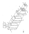
print head 10 illustrated in FIG 1 comprises anactuator section 12 to which liquid ink is supplied fromink supply section 14.Actuator section 12 provides the driving force to eject drops of liquid ink from orifices in aprint element section 16. A fan-insection 18 provides ink channels which extend from theactuator section 12 to theprint element section 16. - The present invention is directed to the
actuator section 12, and this section will be described in detail after a brief description of the other components of theprint head 10. - The
ink supply section 14 comprises an ink supply means 11 which supplies a marking fluid such as liquid ink to amanifold 13. Manifold 13 includes a plurality of openings which connect with corresponding openings in theactuator section 12, in order to feed the liquid ink to each of a plurality of transducers inactuator section 12. - A transducer gasket (not shown) is provided to seal all the ink paths between the
ink supply section 14 and theactuator section 12 in fluid tight relation. - The fan-in
section 18 comprises a plurality of ink channels, one end of each of which is positioned to mate with a corresponding one of the transducers inactuator section 12, and this mating interface is maintained in fluid tight relation by another transducer gasket (not shown). As the ink channels extend through the fan-insection 18 toward theprint element section 16, the spacing of the ink channels converges from the spacing of the transducers inactuator section 12 to the spacing of the orifices inprint element section 16. - The
print element section 16 comprises anorifice plate substrate 21 in which are formed a plurality of openings in registration with the ink channels in fan-insection 18, and the interface is maintained in fluid tight relation by a further gasket member (not shown). Anorifice plate 22 has a plurality of nozzles ororifices 23 in registration with the openings inorifice plate substrate 21. Theorifice plate substrate 21 provides support for thefragile orifice plate 22, and theorifice plate 22 is permanently bonded to theorifice plate substrate 21. The diameter of each of the ink channels through the fan-insection 18, the gasket member 20, and theorifice plate substrate 21 is chosen to provide a good acoustic impedance match in order to minimise reflections of the ejection pressure wave in each channel of the ink drop generator. - In the embodiment shown in Figs. 2 and 3 the
actuator section 12 comprises a plurality ofpiezoelectric tubes 26 which are held in position by atube housing member 24. Tubehousing member 24 can be a moulded plastic part, for example, and comprises a plurality of openings into which thepiezoelectric tubes 26 engage with a close fit. Thepiezoelectric tubes 26 are coated, both inside and outside, with a conductive material that is resistant to corrosion by the liquid ink. Near each end of thetube 26 a gap in the form of aring 28 is formed on the outside of the tube. No conductive material is present in eachring 28. Therings 28 have the effect of producing two electrodes on the tube. Thefirst electrode 30 comprises the portions of conductive material formed on the inside of the tube, around the ends of the tube, and on the outside of the tube near the ends of the tube. Thesecond electrode 32 comprises the portion of conductive material formed in the centre portion of the outside of the tube between the tworings 28. - The
first electrode 30 is connected to a reference potential and thesecond electrode 32 carries the drive signal for each of thepiezoelectric tubes 26. The active portion of eachtube 26 is the centre portion, that is, the portion between the tworings 28. When an electric pulse is applied to thecentre portion electrode 32 of apiezoelectric tube 26, the tube momentarily contracts and generates a pressure wave in the ink inside the tube. A portion of this pressure wave travels forward along the channel from the centre portion of thetube 26 and the forward travelling pressure wave causes the ejection of a drop of ink from thecorresponding orifice 23 when the pressure wave reaches theprint element section 16. - In the embodiment shown in Figs 2 and 3, the
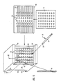
actuator section 12 is divided into two symmetrical halves. Theactuator section 12 comprises a supportingframe 34 having twoidentical halves 36 fastened together and twoidentical module blocks 38 ofpiezoelectric tubes 26. Each module block 38 (FIG. 3) is made of an inexpensive, non-conductive material such as plastic with two columns each having a selected number ofholes 40 through its entire length. Theseholes 40 are made just large enough for free insertion of thepiezoelectric tubes 26. Twoslots block 38 to expose thesignal electrodes 32 and thereference electrodes 30 of thepiezoelectric tubes 26 in the block. Twoelectrical connector members 46 are provided to connect eachelectrode electrical conductor 48 on aflat cable conductor 50. Eachelectrical conductor member 46 comprises aresilient body member 52 which is electrically non-conductive and which has electricallyconductive rings 54 at spaced intervals on its other surface so that electrical contact is made between each one of theconductors 48 and a corresponding one of theelectrodes piezoelectric transducers 26. - The completed
actuator section 12 is fastened to theink supply section 14 and the fan-insection 18 by suitable screws, clamps or clips. A flat gasket member 56 (FIG. 4) having openings corresponding toholes 40 is placed on each end of theactuator section 12. The control signals to produce the desired printed data are coupled to corresponding ones ofconductors 48. - The print head design has many advantages both in fabrication and in operation. The design permits easy repair and replacement of all the components of the print head either at the time of fabrication or in later operation of the print head. No soldering is required for electrical contact, and no epoxy or other bonding material is needed to hold the piezoelectric tubes in position since the
piezoelectric tubes 26 are essentially floating inside themodular block 38 and are self-aligned and self-centered when theactuator section 12 is fastened in place between theink supply section 14 and the fan-insection 18. - As the number of modules required for a high resolution print head increases, the alternative embodiment shown in FIGS. 5-7 makes it easier to retain the relative registration among modules. The print head actuator section is shown in an exploded view in FIG. 5, and comprises a
body member 58 having a plurality ofholes 60 which are arranged in a plurality of rows and extend through theentire body member 58. Arecess 62 is provided in each end ofbody member 58 in the face extending normal to theholes 60 to providestep overhangs 64. A printedcircuit board 66 is provided with a plurality ofholes 68 having the same spacing asholes 60 inbody member 58. A plurality ofelectrical conductors 70 are provided on the printedcircuit board 66. Eachconductor 70 extends from a respective one of theholes 68 to the edge of the printedcircuit board 66. -
Piezoelectric tubes 26 are inserted in each of theholes 60 inbody member 58, and the end of eachpiezoelectric tube 26 is inserted through a corresponding one of theholes 68 in the printedcircuit board 66.Gasket member 74 has a corresponding plurality of holes and the end of each thepiezoelectric tubes 26 in also inserted partially through a corresponding one of the holes ingasket member 74. - A
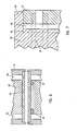
slot 72 is provided along each row ofholes 60 within the recessed face ofbody member 58. When the actuator section is assembled, as shown in FIG. 6, anelectrical connector member 46 is positioned within eachslot 72 to make electrical contact between each one of theelectrodes piezoelectric tubes 26 and a corresponding one of theconductors 70 on printedcircuit board 66. As shown in FIG. 7, the step overhangs 64 on the top and bottom ofbody member 58 provide positive stops when theactuator section 12 is clamped between themanifold section 14 and the fan-insection 18, thereby preventing over-compression of thegasket members 74. - In the embodiment shown in FIGS. 5-7, one
slot 72, and oneconnector member 46 is needed for each column of piezoelectric tubes. However, in a further alternative arrangement shown in FIGS. 8 and 9, two adjacent columns of piezoelectric tubes can utilise one slot and one connector member. As shown in FIG. 9, thepiezoelectric tubes 26 in adjacent columns are staggered, and aslot 76 is cut inbody member 78 which extends between two adjacent columns ofpiezoelectric tubes slot 76, to make electrical contact with each one of theelectrodes piezoelectric tubes conductors circuit board 80. In other respects this arrangement is similar to that shown in FIGS. 5-7. - Several embodiments of the invention have been described, each of which has the advantage of modular design of the actuator section of a print head for an ink jet printer and fabrication advantages which include no soldering operations and no bonding operations. The print heads described are repairable should one or more components require replacement. The modular designs also offer additional advantages in terms of piezoelectric tube registration and alignment.
Claims (8)
a plurality of piezoelectric transducers (26) each having at least one electrode (30, 32),
a housing member (24; 58; 78) for holding said transducers in spaced apart positions,
a conductor member (50; 66; 80) including a plurality of separate electrical conductors (48; 70; 82) thereon and mounted in a fixed position adjacent to said tranducers, and
a connector member (46; 46W) positioned adjacent to said transducers and said conductor member and providing an electrical connection between each electrode (30, 32) on said transducers and a corresponding one of said electrical conductors (48; 70; 82),
characterised in that
said connector member (46) comprises a resilient body and a plurality of electrically conducting elements mounted on said body, and
said connector member is positioned so that each electrically conducting element abuts against a respective electrode and a respective electrical conductor.
two conductor members (50; 66; 80) each including a plurality of separate electrical conductors (48; 70; 82) thereon and mounted in fixed positions adjacent to said tranducers, and
two connector members (46; 46W) positioned adjacent to said transducers and said conductor members and providing an electrical connection between each electrode (30, 32) on said transducers and a corresponding one of said electrical conductors (40; 70; 82),
characterised in that
each connector member (46; 46W) comprises a resilient body and a plurality of electrically conducting elements mounted on said body, and
said connector members are positioned so that each electrically conducting element abuts against a respective electrode and a respective electrical conductor.
Applications Claiming Priority (2)
| Application Number | Priority Date | Filing Date | Title |
|---|---|---|---|
| US923055 | 1986-10-27 | ||
| US06/923,055 US4698644A (en) | 1986-10-27 | 1986-10-27 | Drop-on-demand ink jet print head |
Publications (3)
| Publication Number | Publication Date |
|---|---|
| EP0268395A2 true EP0268395A2 (en) | 1988-05-25 |
| EP0268395A3 EP0268395A3 (en) | 1989-05-24 |
| EP0268395B1 EP0268395B1 (en) | 1992-03-18 |
Family
ID=25448038
Family Applications (1)
| Application Number | Title | Priority Date | Filing Date |
|---|---|---|---|
| EP87309453A Expired - Lifetime EP0268395B1 (en) | 1986-10-27 | 1987-10-26 | Print head for ink jet printer |
Country Status (4)
| Country | Link |
|---|---|
| US (1) | US4698644A (en) |
| EP (1) | EP0268395B1 (en) |
| JP (1) | JPS63112157A (en) |
| DE (1) | DE3777545D1 (en) |
Families Citing this family (14)
| Publication number | Priority date | Publication date | Assignee | Title |
|---|---|---|---|---|
| US5798780A (en) * | 1988-07-03 | 1998-08-25 | Canon Kabushiki Kaisha | Recording element driving unit having extra driving element to facilitate assembly and apparatus using same |
| US5459500A (en) * | 1992-03-25 | 1995-10-17 | Scitex Digital Printing, Inc. | Charge plate connectors and method of making |
| US5437255A (en) * | 1994-03-15 | 1995-08-01 | Sadley; Mark L. | Fuel injection sytem employing solid-state injectors for liquid fueled combustion engines |
| US5474032A (en) * | 1995-03-20 | 1995-12-12 | Krietzman; Mark H. | Suspended feline toy and exerciser |
| US5659346A (en) * | 1994-03-21 | 1997-08-19 | Spectra, Inc. | Simplified ink jet head |
| JP3589277B2 (en) * | 1997-01-27 | 2004-11-17 | セイコーエプソン株式会社 | Ink jet recording head |
| US6070973A (en) * | 1997-05-15 | 2000-06-06 | Massachusetts Institute Of Technology | Non-resonant and decoupled droplet generator |
| JPH1134303A (en) * | 1997-07-15 | 1999-02-09 | Brother Ind Ltd | Recorded |
| JP3267937B2 (en) | 1998-09-04 | 2002-03-25 | 松下電器産業株式会社 | Inkjet head |
| US6402299B1 (en) | 1999-10-22 | 2002-06-11 | Lexmark International, Inc. | Tape automated bonding circuit for use with an ink jet cartridge assembly in an ink jet printer |
| JP3890943B2 (en) * | 2001-10-04 | 2007-03-07 | セイコーエプソン株式会社 | Inkjet recording device |
| US6866825B2 (en) * | 2001-11-05 | 2005-03-15 | Industrial Technology Research Institute | Micro-dispenser for biochemical analysis |
| US7077334B2 (en) * | 2003-04-10 | 2006-07-18 | Massachusetts Institute Of Technology | Positive pressure drop-on-demand printing |
| JP5839944B2 (en) * | 2010-12-24 | 2016-01-06 | キヤノン株式会社 | Liquid discharge head and method of manufacturing liquid discharge head |
Citations (4)
| Publication number | Priority date | Publication date | Assignee | Title |
|---|---|---|---|---|
| DE3324043A1 (en) * | 1983-07-04 | 1985-01-17 | Siemens AG, 1000 Berlin und 8000 München | Piezo-electric drive element for ink mosaic printer |
| US4502059A (en) * | 1982-08-20 | 1985-02-26 | Xerox Corporation | Electrical interconnection system |
| US4584591A (en) * | 1984-05-16 | 1986-04-22 | Siemens Aktiengesellschaft | Fastening and connecting arrangement for piezoelectric driving elements in the write heads of ink writing devices |
| US4588999A (en) * | 1984-05-18 | 1986-05-13 | Siemens Aktiengesellschaft | Device for the fixing and contacting of piezotubes |
Family Cites Families (8)
| Publication number | Priority date | Publication date | Assignee | Title |
|---|---|---|---|---|
| US3683212A (en) * | 1970-09-09 | 1972-08-08 | Clevite Corp | Pulsed droplet ejecting system |
| JPS5555985U (en) * | 1978-10-12 | 1980-04-16 | ||
| US4357061A (en) * | 1980-02-28 | 1982-11-02 | Beckman Instruments, Inc. | Electro-mechanical package of visual display and related circuitry |
| US4390886A (en) * | 1981-09-25 | 1983-06-28 | Xerox Corporation | Ink jet printing machine |
| US4418356A (en) * | 1981-09-23 | 1983-11-29 | Ncr Corporation | Ink jet print head |
| DE3208679A1 (en) * | 1982-03-10 | 1983-09-22 | Siemens AG, 1000 Berlin und 8000 München | DEVICE FOR CONTACTING TUBE-SHAPED PIEZWALKERS TO BE PLASTED IN PLASTIC |
| US4485388A (en) * | 1982-07-21 | 1984-11-27 | Ncr Corporation | Compact print head |
| JPS60204340A (en) * | 1984-03-30 | 1985-10-15 | Canon Inc | Liquid jet recording apparatus |
-
1986
- 1986-10-27 US US06/923,055 patent/US4698644A/en not_active Expired - Fee Related
-
1987
- 1987-05-15 JP JP62117256A patent/JPS63112157A/en active Pending
- 1987-10-26 EP EP87309453A patent/EP0268395B1/en not_active Expired - Lifetime
- 1987-10-26 DE DE8787309453T patent/DE3777545D1/en not_active Expired - Fee Related
Patent Citations (4)
| Publication number | Priority date | Publication date | Assignee | Title |
|---|---|---|---|---|
| US4502059A (en) * | 1982-08-20 | 1985-02-26 | Xerox Corporation | Electrical interconnection system |
| DE3324043A1 (en) * | 1983-07-04 | 1985-01-17 | Siemens AG, 1000 Berlin und 8000 München | Piezo-electric drive element for ink mosaic printer |
| US4584591A (en) * | 1984-05-16 | 1986-04-22 | Siemens Aktiengesellschaft | Fastening and connecting arrangement for piezoelectric driving elements in the write heads of ink writing devices |
| US4588999A (en) * | 1984-05-18 | 1986-05-13 | Siemens Aktiengesellschaft | Device for the fixing and contacting of piezotubes |
Also Published As
| Publication number | Publication date |
|---|---|
| EP0268395A3 (en) | 1989-05-24 |
| DE3777545D1 (en) | 1992-04-23 |
| US4698644A (en) | 1987-10-06 |
| EP0268395B1 (en) | 1992-03-18 |
| JPS63112157A (en) | 1988-05-17 |
Similar Documents
| Publication | Publication Date | Title |
|---|---|---|
| EP0268395B1 (en) | Print head for ink jet printer | |
| EP0786342B1 (en) | Ink jet print head and nozzle plate used therefor | |
| JP3534762B2 (en) | INK JET PRINT HEAD DEVICE AND ITS MANUFACTURING METHOD | |
| US4878070A (en) | Thermal ink jet print cartridge assembly | |
| US5535494A (en) | Method of fabricating a piezoelectric ink jet printhead assembly | |
| EP0916497B1 (en) | Ink-jet recording head | |
| JPH07125380A (en) | Modular carriage assembly for ink jet printer and assemblingmethod thereof | |
| JPH06340064A (en) | Single interconnected system | |
| JP2007196455A (en) | Head module, liquid ejecting head and liquid ejector | |
| US6371604B1 (en) | Ink jet recording head assembly having an urging member for contacting components thereof, the urging member having an ink supply mechanism, and ink jet head cartridge and ink jet apparatus having the same | |
| US5870118A (en) | Ink-jet printer head formed of multiple ink-jet printer modules | |
| US4493137A (en) | Method of making a drive element assembly for ink jet printing | |
| JP2003080793A (en) | Recorder | |
| US5992976A (en) | Ink-jet printhead | |
| US6003974A (en) | Unitary interconnect system for an inkjet printer | |
| JPH10100401A (en) | Ink jet head | |
| EP0113770B1 (en) | Ink jet print head | |
| US6431690B1 (en) | Ink jet head and producing process therefor | |
| US10179450B2 (en) | Liquid discharge head | |
| JP2822963B2 (en) | Inkjet recording head | |
| CN110962457B (en) | Liquid ejection head | |
| JP3812058B2 (en) | Inkjet recording head | |
| JP7346148B2 (en) | liquid discharge head | |
| JP3149532B2 (en) | Inkjet head | |
| JP2000079687A (en) | Recording head and recorder employing it |
Legal Events
| Date | Code | Title | Description |
|---|---|---|---|
| PUAI | Public reference made under article 153(3) epc to a published international application that has entered the european phase |
Free format text: ORIGINAL CODE: 0009012 |
|
| AK | Designated contracting states |
Kind code of ref document: A2 Designated state(s): DE FR GB IT |
|
| 17P | Request for examination filed |
Effective date: 19880823 |
|
| PUAL | Search report despatched |
Free format text: ORIGINAL CODE: 0009013 |
|
| AK | Designated contracting states |
Kind code of ref document: A3 Designated state(s): DE FR GB IT |
|
| 17Q | First examination report despatched |
Effective date: 19901031 |
|
| RAP1 | Party data changed (applicant data changed or rights of an application transferred) |
Owner name: LEXMARK INTERNATIONAL, INC. |
|
| GRAA | (expected) grant |
Free format text: ORIGINAL CODE: 0009210 |
|
| AK | Designated contracting states |
Kind code of ref document: B1 Designated state(s): DE FR GB IT |
|
| REF | Corresponds to: |
Ref document number: 3777545 Country of ref document: DE Date of ref document: 19920423 |
|
| 111Z | Information provided on other rights and legal means of execution |
Free format text: DE FR GB IT |
|
| R11X | Information provided on other rights and legal means of execution (corrected) |
Free format text: DE FR GB IT |
|
| ET | Fr: translation filed | ||
| ITF | It: translation for a ep patent filed |
Owner name: SOCIETA' ITALIANA BREVETTI S.P.A. |
|
| PLBE | No opposition filed within time limit |
Free format text: ORIGINAL CODE: 0009261 |
|
| STAA | Information on the status of an ep patent application or granted ep patent |
Free format text: STATUS: NO OPPOSITION FILED WITHIN TIME LIMIT |
|
| 26N | No opposition filed | ||
| PGFP | Annual fee paid to national office [announced via postgrant information from national office to epo] |
Ref country code: FR Payment date: 19950913 Year of fee payment: 9 |
|
| PGFP | Annual fee paid to national office [announced via postgrant information from national office to epo] |
Ref country code: DE Payment date: 19950925 Year of fee payment: 9 |
|
| PGFP | Annual fee paid to national office [announced via postgrant information from national office to epo] |
Ref country code: GB Payment date: 19950927 Year of fee payment: 9 |
|
| PG25 | Lapsed in a contracting state [announced via postgrant information from national office to epo] |
Ref country code: GB Effective date: 19961026 |
|
| GBPC | Gb: european patent ceased through non-payment of renewal fee |
Effective date: 19961026 |
|
| PG25 | Lapsed in a contracting state [announced via postgrant information from national office to epo] |
Ref country code: FR Effective date: 19970630 |
|
| PG25 | Lapsed in a contracting state [announced via postgrant information from national office to epo] |
Ref country code: DE Effective date: 19970701 |
|
| REG | Reference to a national code |
Ref country code: FR Ref legal event code: ST |
|
| PG25 | Lapsed in a contracting state [announced via postgrant information from national office to epo] |
Ref country code: IT Free format text: LAPSE BECAUSE OF NON-PAYMENT OF DUE FEES;WARNING: LAPSES OF ITALIAN PATENTS WITH EFFECTIVE DATE BEFORE 2007 MAY HAVE OCCURRED AT ANY TIME BEFORE 2007. THE CORRECT EFFECTIVE DATE MAY BE DIFFERENT FROM THE ONE RECORDED. Effective date: 20051026 |