EP0268445B1 - Improvements in or relating to injection devices - Google Patents
Improvements in or relating to injection devices Download PDFInfo
- Publication number
- EP0268445B1 EP0268445B1 EP87310097A EP87310097A EP0268445B1 EP 0268445 B1 EP0268445 B1 EP 0268445B1 EP 87310097 A EP87310097 A EP 87310097A EP 87310097 A EP87310097 A EP 87310097A EP 0268445 B1 EP0268445 B1 EP 0268445B1
- Authority
- EP
- European Patent Office
- Prior art keywords
- sleeve
- needle
- accessory
- injection
- point
- Prior art date
- Legal status (The legal status is an assumption and is not a legal conclusion. Google has not performed a legal analysis and makes no representation as to the accuracy of the status listed.)
- Expired
Links
Images

Classifications
-
- A—HUMAN NECESSITIES
- A61—MEDICAL OR VETERINARY SCIENCE; HYGIENE
- A61M—DEVICES FOR INTRODUCING MEDIA INTO, OR ONTO, THE BODY; DEVICES FOR TRANSDUCING BODY MEDIA OR FOR TAKING MEDIA FROM THE BODY; DEVICES FOR PRODUCING OR ENDING SLEEP OR STUPOR
- A61M5/00—Devices for bringing media into the body in a subcutaneous, intra-vascular or intramuscular way; Accessories therefor, e.g. filling or cleaning devices, arm-rests
- A61M5/178—Syringes
- A61M5/31—Details
- A61M5/32—Needles; Details of needles pertaining to their connection with syringe or hub; Accessories for bringing the needle into, or holding the needle on, the body; Devices for protection of needles
- A61M5/3205—Apparatus for removing or disposing of used needles or syringes, e.g. containers; Means for protection against accidental injuries from used needles
- A61M5/321—Means for protection against accidental injuries by used needles
- A61M5/3243—Means for protection against accidental injuries by used needles being axially-extensible, e.g. protective sleeves coaxially slidable on the syringe barrel
- A61M5/3271—Means for protection against accidental injuries by used needles being axially-extensible, e.g. protective sleeves coaxially slidable on the syringe barrel with guiding tracks for controlled sliding of needle protective sleeve from needle exposing to needle covering position
-
- A—HUMAN NECESSITIES
- A61—MEDICAL OR VETERINARY SCIENCE; HYGIENE
- A61M—DEVICES FOR INTRODUCING MEDIA INTO, OR ONTO, THE BODY; DEVICES FOR TRANSDUCING BODY MEDIA OR FOR TAKING MEDIA FROM THE BODY; DEVICES FOR PRODUCING OR ENDING SLEEP OR STUPOR
- A61M5/00—Devices for bringing media into the body in a subcutaneous, intra-vascular or intramuscular way; Accessories therefor, e.g. filling or cleaning devices, arm-rests
- A61M5/178—Syringes
- A61M5/28—Syringe ampoules or carpules, i.e. ampoules or carpules provided with a needle
- A61M5/281—Syringe ampoules or carpules, i.e. ampoules or carpules provided with a needle using emptying means to expel or eject media, e.g. pistons, deformation of the ampoule, or telescoping of the ampoule
- A61M5/283—Syringe ampoules or carpules, i.e. ampoules or carpules provided with a needle using emptying means to expel or eject media, e.g. pistons, deformation of the ampoule, or telescoping of the ampoule by telescoping of ampoules or carpules with the syringe body
-
- A—HUMAN NECESSITIES
- A61—MEDICAL OR VETERINARY SCIENCE; HYGIENE
- A61M—DEVICES FOR INTRODUCING MEDIA INTO, OR ONTO, THE BODY; DEVICES FOR TRANSDUCING BODY MEDIA OR FOR TAKING MEDIA FROM THE BODY; DEVICES FOR PRODUCING OR ENDING SLEEP OR STUPOR
- A61M5/00—Devices for bringing media into the body in a subcutaneous, intra-vascular or intramuscular way; Accessories therefor, e.g. filling or cleaning devices, arm-rests
- A61M5/50—Devices for bringing media into the body in a subcutaneous, intra-vascular or intramuscular way; Accessories therefor, e.g. filling or cleaning devices, arm-rests having means for preventing re-use, or for indicating if defective, used, tampered with or unsterile
- A61M5/5013—Means for blocking the piston or the fluid passageway to prevent illegal refilling of a syringe
-
- A—HUMAN NECESSITIES
- A61—MEDICAL OR VETERINARY SCIENCE; HYGIENE
- A61M—DEVICES FOR INTRODUCING MEDIA INTO, OR ONTO, THE BODY; DEVICES FOR TRANSDUCING BODY MEDIA OR FOR TAKING MEDIA FROM THE BODY; DEVICES FOR PRODUCING OR ENDING SLEEP OR STUPOR
- A61M5/00—Devices for bringing media into the body in a subcutaneous, intra-vascular or intramuscular way; Accessories therefor, e.g. filling or cleaning devices, arm-rests
- A61M5/50—Devices for bringing media into the body in a subcutaneous, intra-vascular or intramuscular way; Accessories therefor, e.g. filling or cleaning devices, arm-rests having means for preventing re-use, or for indicating if defective, used, tampered with or unsterile
- A61M5/508—Means for preventing re-use by disrupting the piston seal, e.g. by puncturing
-
- A—HUMAN NECESSITIES
- A61—MEDICAL OR VETERINARY SCIENCE; HYGIENE
- A61M—DEVICES FOR INTRODUCING MEDIA INTO, OR ONTO, THE BODY; DEVICES FOR TRANSDUCING BODY MEDIA OR FOR TAKING MEDIA FROM THE BODY; DEVICES FOR PRODUCING OR ENDING SLEEP OR STUPOR
- A61M5/00—Devices for bringing media into the body in a subcutaneous, intra-vascular or intramuscular way; Accessories therefor, e.g. filling or cleaning devices, arm-rests
- A61M5/178—Syringes
- A61M5/31—Details
- A61M2005/3117—Means preventing contamination of the medicament compartment of a syringe
- A61M2005/3118—Means preventing contamination of the medicament compartment of a syringe via the distal end of a syringe, i.e. syringe end for mounting a needle cannula
- A61M2005/312—Means preventing contamination of the medicament compartment of a syringe via the distal end of a syringe, i.e. syringe end for mounting a needle cannula comprising sealing means, e.g. severable caps, to be removed prior to injection by, e.g. tearing or twisting
-
- A—HUMAN NECESSITIES
- A61—MEDICAL OR VETERINARY SCIENCE; HYGIENE
- A61M—DEVICES FOR INTRODUCING MEDIA INTO, OR ONTO, THE BODY; DEVICES FOR TRANSDUCING BODY MEDIA OR FOR TAKING MEDIA FROM THE BODY; DEVICES FOR PRODUCING OR ENDING SLEEP OR STUPOR
- A61M5/00—Devices for bringing media into the body in a subcutaneous, intra-vascular or intramuscular way; Accessories therefor, e.g. filling or cleaning devices, arm-rests
- A61M5/178—Syringes
- A61M5/31—Details
- A61M2005/3128—Incorporating one-way valves, e.g. pressure-relief or non-return valves
-
- A—HUMAN NECESSITIES
- A61—MEDICAL OR VETERINARY SCIENCE; HYGIENE
- A61M—DEVICES FOR INTRODUCING MEDIA INTO, OR ONTO, THE BODY; DEVICES FOR TRANSDUCING BODY MEDIA OR FOR TAKING MEDIA FROM THE BODY; DEVICES FOR PRODUCING OR ENDING SLEEP OR STUPOR
- A61M5/00—Devices for bringing media into the body in a subcutaneous, intra-vascular or intramuscular way; Accessories therefor, e.g. filling or cleaning devices, arm-rests
- A61M5/178—Syringes
- A61M5/31—Details
- A61M5/32—Needles; Details of needles pertaining to their connection with syringe or hub; Accessories for bringing the needle into, or holding the needle on, the body; Devices for protection of needles
- A61M5/3205—Apparatus for removing or disposing of used needles or syringes, e.g. containers; Means for protection against accidental injuries from used needles
- A61M5/321—Means for protection against accidental injuries by used needles
- A61M5/3243—Means for protection against accidental injuries by used needles being axially-extensible, e.g. protective sleeves coaxially slidable on the syringe barrel
- A61M5/326—Fully automatic sleeve extension, i.e. in which triggering of the sleeve does not require a deliberate action by the user
- A61M2005/3267—Biased sleeves where the needle is uncovered by insertion of the needle into a patient's body
-
- A—HUMAN NECESSITIES
- A61—MEDICAL OR VETERINARY SCIENCE; HYGIENE
- A61M—DEVICES FOR INTRODUCING MEDIA INTO, OR ONTO, THE BODY; DEVICES FOR TRANSDUCING BODY MEDIA OR FOR TAKING MEDIA FROM THE BODY; DEVICES FOR PRODUCING OR ENDING SLEEP OR STUPOR
- A61M5/00—Devices for bringing media into the body in a subcutaneous, intra-vascular or intramuscular way; Accessories therefor, e.g. filling or cleaning devices, arm-rests
- A61M5/178—Syringes
- A61M5/31—Details
- A61M5/32—Needles; Details of needles pertaining to their connection with syringe or hub; Accessories for bringing the needle into, or holding the needle on, the body; Devices for protection of needles
- A61M5/3205—Apparatus for removing or disposing of used needles or syringes, e.g. containers; Means for protection against accidental injuries from used needles
- A61M5/321—Means for protection against accidental injuries by used needles
- A61M5/3243—Means for protection against accidental injuries by used needles being axially-extensible, e.g. protective sleeves coaxially slidable on the syringe barrel
- A61M5/326—Fully automatic sleeve extension, i.e. in which triggering of the sleeve does not require a deliberate action by the user
-
- A—HUMAN NECESSITIES
- A61—MEDICAL OR VETERINARY SCIENCE; HYGIENE
- A61M—DEVICES FOR INTRODUCING MEDIA INTO, OR ONTO, THE BODY; DEVICES FOR TRANSDUCING BODY MEDIA OR FOR TAKING MEDIA FROM THE BODY; DEVICES FOR PRODUCING OR ENDING SLEEP OR STUPOR
- A61M5/00—Devices for bringing media into the body in a subcutaneous, intra-vascular or intramuscular way; Accessories therefor, e.g. filling or cleaning devices, arm-rests
- A61M5/178—Syringes
- A61M5/31—Details
- A61M5/32—Needles; Details of needles pertaining to their connection with syringe or hub; Accessories for bringing the needle into, or holding the needle on, the body; Devices for protection of needles
- A61M5/3205—Apparatus for removing or disposing of used needles or syringes, e.g. containers; Means for protection against accidental injuries from used needles
- A61M5/321—Means for protection against accidental injuries by used needles
- A61M5/3243—Means for protection against accidental injuries by used needles being axially-extensible, e.g. protective sleeves coaxially slidable on the syringe barrel
- A61M5/3271—Means for protection against accidental injuries by used needles being axially-extensible, e.g. protective sleeves coaxially slidable on the syringe barrel with guiding tracks for controlled sliding of needle protective sleeve from needle exposing to needle covering position
- A61M5/3272—Means for protection against accidental injuries by used needles being axially-extensible, e.g. protective sleeves coaxially slidable on the syringe barrel with guiding tracks for controlled sliding of needle protective sleeve from needle exposing to needle covering position having projections following labyrinth paths
-
- A—HUMAN NECESSITIES
- A61—MEDICAL OR VETERINARY SCIENCE; HYGIENE
- A61M—DEVICES FOR INTRODUCING MEDIA INTO, OR ONTO, THE BODY; DEVICES FOR TRANSDUCING BODY MEDIA OR FOR TAKING MEDIA FROM THE BODY; DEVICES FOR PRODUCING OR ENDING SLEEP OR STUPOR
- A61M5/00—Devices for bringing media into the body in a subcutaneous, intra-vascular or intramuscular way; Accessories therefor, e.g. filling or cleaning devices, arm-rests
- A61M5/178—Syringes
- A61M5/31—Details
- A61M5/32—Needles; Details of needles pertaining to their connection with syringe or hub; Accessories for bringing the needle into, or holding the needle on, the body; Devices for protection of needles
- A61M5/34—Constructions for connecting the needle, e.g. to syringe nozzle or needle hub
- A61M5/348—Constructions for connecting the needle, e.g. to syringe nozzle or needle hub snap lock, i.e. upon axial displacement of needle assembly
Definitions
- This invention relates to injection devices, such as syringes, and accessories therefor.
- needle stick After use of a syringe to perform an injection or take up a sample of blood from a patient, there is a risk that doctors or nurses will accidentally prick themselves with the needle of the syringe. This phenomenon is known as "needle stick", and can be highly dangerous due to the risk of transfer of blood-related diseases.
- US-A-4425120 discloses a syringe which includes a protective sleeve for surrounding the needle and slidable on the syringe barrel between a contracted position in which the point of the needle projects from the sleeve to an extent to enable an injection to be effected, and an extended position in which the point of the needle is located within the sleeve to shield the point of the needle.
- the sleeve is temporarily held in the contracted position by engaging a track at one end of the sleeve with a first projection on the barrel, the injection then being performed in the normal manner.
- the sleeve is manually released from the contracted position and moved into the extended position in which it is manually locked by engagement of a track at the other end of the sleeve with a second projection on the barrel.
- this arrangement is not sufficient to prevent needle stick since, in order to manually move the sleeve to its extended position to shield the needle, the user's free hand must be placed close to the end of the syringe, and this operation can therefore itself lead to needle stick if it is performed with insufficient manual dexterity.
- an accessory for an injection device of the kind in which liquid is drawn or expelled along a hollow needle comprising a protective sleeve for surrounding the needle and having at least an end portion which is movable with respect to the needle in the direction of the length of the sleeve from a contracted position, in which, when the accessory is used with the injection device, the point of the needle projects from the sleeve to an extent to enable an injection to be effected, to an extended position, in which, when the accessory is used with the injection device, the point of the needle is located within the sleeve to shield the point of the needle, and retaining means for retaining the sleeve in the extended position after the injection has been effected such that, when the accessory is used with the injection device, the point of the needle is prevented from being exposed solely by application of pressure to the end portion of the sleeve in the direction of contracting movement, characterised by biasing means for resiliently biasing the sleeve towards it extended
- injection device is used in this context to cover both a device for introducing a substance into a site penetrated by a needle and a device for taking up a substance, such as blood, from a site penetrated by a needle.
- an accessory in the form of an extendible sleeve 1 is shown fitted to one end of a syringe 2 comprising a hollow cylindrical barrel and a plunger (not shown) displaceable within the barrel.
- the syringe 2 has an outlet 7 at one end to which a hollow needle 9 is attached by means of an integral connector 8 which is a push fit on the outlet 7.
- the extendible sleeve 1 comprises two telescoping sleeve parts 10 and 11, and an inner member 12.
- the sleeve part 10 surrounds the inner member 12 and is connected thereto by an annular rib 13 on the inside surface of the sleeve part 10 which engages by a snap action in an annular groove 14 in the outside surface of a base portion 15 of the inner member 12.
- the base portion 15 of the inner member 12 is a push fit on the needle connector 8.
- the sleeve part 11 tapers towards its end furthest from the syringe 2 and has an aperture 17 at that end for passage of the point of the needle 9.
- the outside surface of the sleeve part 11 is formed with four equiangularly spaced longitudinal ribs 18 engaging the inside surface of the sleeve part 10 and at least one projection 19 engaging within a respective track 20 extending partially or completely through the wall of the sleeve part 10.
- the sleeve 1 is resiliently biased towards its extended position by means of a compression spring 16 within the sleeve part 10 acting between the base portion 15 of the inner member 12 and the sleeve part 11.
- the spring 16 is a relatively weak spring which is reduced in diameter at an intermediate region along its length so that it has a small length when fully compressed.
- the track 20 in the sleeve part 10 extends parallel to the needle 9 from the end of the sleeve part 10 adjacent the syringe 2 to a region a short distance from the opposite end of the sleeve part 10. Furthermore, as shown in the explanatory diagram of Figure 3, the slot 20 is formed in that region with a retaining means in the form of a hooked portion 22 of the track 20 and an additional retaining means in the form of a shaped notch 21 in one side wall of the track 20.
- the accessory 1 is fitted to the needle connector 8 after loading of the syringe 2 with injectate in conventional manner.
- the accessory 1 is initially in its extended position in which the point of the needle 9 is shielded by the sleeve part 11 as shown in Figure 1.
- the projection 19 on the sleeve part 11 is in the hooked portion 22 of the track 20 in the sleeve part 10, as shown at 19' in Figure 3.
- the shape of the hooked portion 22 is such as to enable limited movement of the sleeve part 11 inwardly of the sleeve part 10 by application of pressure to the end of the sleeve part 11, but is such as to prevent inward movement of the sleeve part 11 to an extent to enable the point of the needle 9 to project from the aperture 17 at the end of the sleeve part 11.
- the sleeve part 11 is then twisted to release the projection 19 from the hooked portion 22 and to enable the projection 19 to enter the notch 21, as shown at 19" in Figure 3, and to be retained therein by the biasing action of the spring 16.
- the accessory is thereby contracted to an extent to enable the point of the needle 9 to project through the aperture 17 in the end of the sleeve part 11 to a small extent. This then enables the point of the needle 9 to be accurately positioned at the intended site of injection.
- the accessory when the accessory is contracted in this manner, the point of the needle 9 still does not project through the end of the sleeve part 11.
- the point of the needle 9 When the dose has been delivered, the point of the needle 9 is withdrawn from the site of injection causing the sleeve part 11 to be returned to its extended position by the action of the spring 16, the projection 19 moving back along the straight portion of the track 20 and entering the hooked portion 22.
- withdrawal of the point of the needle 9 from the patient automatically causes the accessory 1 to be returned to its secure position in which the point of the needle 9 is shielded by the sleeve part 11, and the point of the needle 9 cannot be subsequently exposed simply by application of pressure to the end of the sleeve part 11. Only by applying a positive twisting action to the sleeve part 11 can the point of the needle be subsequently re-exposed.
- the notch 21 may be dispensed with.
- the retaining means constituted by the hooked portion 22 may also be of a different form to that described above.
- it may take the form of a skirt on the outside of the sleeve part 11 which must be manually depressed to enable it to be overridden by the sleeve part 10 and allow contracting movement of the sleeve part 11.
- the accessory is used for taking a blood sample
- the outlet of the syringe to which the needle connector is connected may be formed with a weakened region which may be fractured to detach the needle and sleeve from the syringe.
- the arrangement should preferably be such that a fresh needle cannot be connected to the fractured syringe outlet.
- the accessory may also be used with arrangements in which a syringe as such is not provided, such as the so-called Vacutainer (Registered Trade Mark) arrangement.
- Vacutainer Registered Trade Mark
- the needle is extended beyond the needle connector, the extension of the needle being covered by a rubber sleeve which is closed at its free end.
- the extension of the needle After insertion of the point of the needle into the site of injection for the purpose of taking a blood sample, the extension of the needle, which is pointed at its end, is caused to puncture the rubber bung of a pre-evacuated container, the rubber sleeve being pushed back by this operation to enable the point of the extension to pass through the bung.
- the vacuum within the con- tainerthen causes blood to be drawn from the site of injection into the container.
- an accessory of the type described above may be used not only to protect the injection end of the needle but also to protect the extension of the needle for insertion into the pre-evacuated container (in which case the rubber sleeve may be dispensed with).
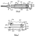
- Figure 4 shows another form of accessory in accordance with the invention, like parts being given the same reference numerals as in Figures 1 to 3.
- the extendible sleeve 1 is shown fitted to one end of a syringe 2 comprising a hollow cylindrical barrel 3 and a plunger 4 displaceable within the barrel 3.
- the plunger 4 comprises a hollow cylindrical shaft 5 and a piston part 6 made of resilient material and having a portion which is a force fit within the end of the shaft 5.
- the sleeve part 10 is connectable to the connector 7A surrounding the outlet 7 of the syringe 2 by means of an annular rib 32 on the connector 7A which engages within an annular groove 33 in the inside surface of the sleeve part 10. It is preferred that the rib 32 and groove 33 have a section as shown so as to prevent subsequent detachment of the sleeve part 10 after attachment to the connector 7A. However, it is also feasible for the connection between these two parts to be by means of a screwthread or a bayonet fitting, optionally including a stop within the screwthread or fitting which is overridden on fitting of the sleeve to the connector, but which subsequently prevents the sleeve from being detached from the connector.
- the sleeve part 11 has a tab portion 34 which is detachable from the end of the sleeve part 11, preferably by twisting, so as to cause the material of the end of the sleeve part 11 to rupture in the vicinity of an annular weakened region 35, thereby forming an aperture through which the point of the needle 9 may pass through the end of the sleeve part 11.
- the sleeve 1 includes an arrangement for locking the sleeve in its extended position, this arrangement comprising a pin 19 projecting from the outside surface of the sleeve part 11 engaging within a hook-shaped track 30 in the inside surface of the sleeve part 10.
- the track 30 preferably does not extend completely through the wall of the sleeve part 10.
- the above-described accessory is used in substantially similar manner to the accessory of Figures 1 to 3 to perform an injection.
- the tab 34 must be detached from the end of the sleeve part 11 immediately prior to the injection being carried out, and the resulting apertured end of the sleeve part 11 is applied to the site of injection.
- the sleeve part 11 is then twisted to release the pin 19 from the hooked portion of the track 30, and simultaneously pressure is applied to the syringe to cause the sleeve part 11 to telescope within the sleeve part 10, thus causing the pin 19 to travel along the straight portion of the track 30 and the point of the needle 9 to pass through the apertured end of the sleeve part 11.
- the blood sample may be taken up into the syringe in a substantially analogous manner to that described above in relation to delivery of injectate to a site of injection, except that the plunger 4 will of course be drawn in the direction away from the outlet 7 in this operation.
- the sleeve After taking up of the blood sample, the sleeve will reassume its extended position and will again be locked in this position so that the danger of needle stick is substantially removed.
- the apertured end of the sleeve part 11 is applied to the top of the container, and the sleeve part is rotated to free the pin 19 from the hooked portion of the slot 20 whilst applying pressure to the syringe to cause the point of the needle 9 to pass through the apertured end of the sleeve part 11 and to puncture the top of the container.
- the blood sample may then be discharged through the needle 9 into the container in conventional manner, and again, on withdrawing the point of the needle, the sleeve will again reassume its extended position and will be locked in this position.
- the syringe is then disposed of with the sleeve still attached to protect the point of the needle.
- the pin 19 and slot 20 are dispensed with, and instead the outside surface of the sleeve part 11 and the inside surface of the sleeve part 10 are provided with complementary locking formations 42 and 41.
- the locking formations 42 and 41 may be in the form of annular ribs or one or more projections which do not extend continuously around the periphery of the sleeve parts 10 and 11.
- the relative positions of the formations 42 and 41 will be as shown in Figure 5, so that the sleeve 11 may be telescoped within the sleeve part 10 without requiring initial twisting of the sleeve part 11.
- the formation 42 on the sleeve part 11 will be caused by the applied spring force to override the formation 41 so that the formation 42 will be moved to a position, as shown in broken lines at 42' in Figure 5, in which it engages behind the formation 41. It will be appreciated that this will result in the sleeve 1 being locked in its extended position.
- the form of the interlocking formations may be such that such locking is permanent and cannot be overridden.
- the syringe may be arranged that the sleeve part 11 may be subsequently telescoped within the sleeve part 10 by application of a relatively large force to the sleeve part 11 in the direction towards the syringe.
- Figures 6 and 7 show a further form of accessory which is intended to remain permanently attached to the syringe 201 both during loading of the syringe with injectate and during injection.
- the syringe 201 comprises a hollow cylindrical barrel 202 and a plunger piston 205 having an outlet 203.
- the outlet 203 is defined by a connector 204 to which a hollow needle 206 is permanently attached.
- a guide sleeve 207 whose function will become apparent from the description below, is also attached to the connector 204.
- a protective sleeve 208 surrounds the needle 206 and is biased into its extended position by a compression spring 209 within the guide sleeve 207. Furthermore the protective sleeve 208 is coupled to the guide sleeve 207 by a pin projecting outwardly from the sleeve 208 which engages within a guide track in the guide sleeve 207.
- the sleeve 207 is made of nylon and incorporates fingers 211, 212, 213, 214 and 215 which allow movement of the pin 216 along the guide track 210 in one direction, but prevent movement of the pin 216 in the opposite direction.
- the sleeves 207 and 208 are fitted together so that the pin 216 is moved into the guide track 210 and beyond the finger 211 to the position shown in solid lines in Figure 7.
- the protective sleeve 208 In operation of the syringe to perform an injection, the protective sleeve 208 is initially in its fully extended position, as shown in Figure 6, in which it extends beyond the end of the needle 206, and the piston 205 is close to the closed end of the barrel 202. In order to uncover the tip of the needle 206 the protective sleeve 208 is manually grasped by means of a flange portion 217 thereon and is twisted relative to the barrel 202, whilst applying slight pressure to the flange 217 against the action of the spring 209, in order to release the pin 216 from the locked position shown in solid lines in Figure 7. The pin 216 is thereby moved into the position 218 shown in broken lines.
- the sleeve 208 may be moved inwardly of the barrel 202 to fully compress the spring 209 and to move the pin 216 past the finger 212 to the position 219. This movement exposes the tip of the needle 206 and at the same time causes the piston 205 to be moved to the end of the barrel 202 to expel air from the chamber 220.
- the tip of the needle 206 may then be introduced into an injectate bottle and the sleeve 208 manually moved in the direction of the arrow 221 in Figure 6. This causes the pin 216 in the guide track 210 to be moved beyond the finger 213 to the position 222 shown in Figure 7. Further movement of the sleeve 208 in the direction of the arrow 221 causes the piston 205 to be drawn along the barrel 202 in the same direction in order to draw injectate along the needle 206 into the chamber 220. The syringe is held in this position prior to the injection being effected.
- a compression spring 230 may be provided within the chamber 220 so that the syringe is automatically filled with injectate when pressure is released from the sleeve 208.
- the sleeve 208 is then again moved to compress the spring 209, firstly to expel any excess air from the chamber 220 and then, after insertion of the tip of the needle 206 into the injection site, in order to deliver the dose of injectate through the needle 206.
- Initial compression of the sleeve 208 causes movement of the pin 216 in the guide track 210 beyond the finger 214 to the position 223.
- Subsequent movement of the sleeve 208 in the same direction then causes movement of the piston 205 to expel air and subsequently injectate from the chamber 220.
- the sleeve 208 On completion of the injection the sleeve 208 is released to enable it to be moved into its fully extended position under the action of the spring 207, and the pin 216 is thereby moved in the guide track 210 beyond the finger 215 to the position 224 in which the sleeve 208 is locked in its extended position. In this position the sleeve 208 is locked in position relative to the sleeve 207 and hence also to the piston 205, although it is still possible for the piston 205 to be moved within the barrel 202 by moving the sleeve 208. Nevertheless such movement cannot be used to draw injectate into the chamber 220 by way of the needle 206 since the needle 206 is permanently covered by the sleeve 208.
- a pressure fill stop pipe 225 is located on the inner end wall of the barrel 202 for engaging a seating 226 on the opposite wall of the piston 205 when the piston 205 is in its endmost position.
- connection between the piston 205 and the guide sleeve 207 by way of the connector 204 may either enable relative rotation between the sleeve 207 and the piston 205 or may prevent such rotation.
- fingers may be provided on the free end of the protective sleeve 208 extending radially outwardly relative to the needle 206 and shaped to fit around the injectate bottle as an aid to filling of the syringe with injectate.
- the number and extent of the forward and backward movements of the sleeve 208 required in an injection cycle can be varied depending on the intended use and method of operation of the syringe.
Abstract
Description
- This invention relates to injection devices, such as syringes, and accessories therefor.
- After use of a syringe to perform an injection or take up a sample of blood from a patient, there is a risk that doctors or nurses will accidentally prick themselves with the needle of the syringe. This phenomenon is known as "needle stick", and can be highly dangerous due to the risk of transfer of blood-related diseases.
- US-A-4425120 discloses a syringe which includes a protective sleeve for surrounding the needle and slidable on the syringe barrel between a contracted position in which the point of the needle projects from the sleeve to an extent to enable an injection to be effected, and an extended position in which the point of the needle is located within the sleeve to shield the point of the needle. In order to perform an injection, the sleeve is temporarily held in the contracted position by engaging a track at one end of the sleeve with a first projection on the barrel, the injection then being performed in the normal manner. After the injection has been carried out, the sleeve is manually released from the contracted position and moved into the extended position in which it is manually locked by engagement of a track at the other end of the sleeve with a second projection on the barrel. However, this arrangement is not sufficient to prevent needle stick since, in order to manually move the sleeve to its extended position to shield the needle, the user's free hand must be placed close to the end of the syringe, and this operation can therefore itself lead to needle stick if it is performed with insufficient manual dexterity.
- It is an object of the invention to provide an accessory for a syringe or other injection device which substantially eliminates the danger of needle stick.
- According to the present invention there is provided an accessory for an injection device of the kind in which liquid is drawn or expelled along a hollow needle, the accessory comprising a protective sleeve for surrounding the needle and having at least an end portion which is movable with respect to the needle in the direction of the length of the sleeve from a contracted position, in which, when the accessory is used with the injection device, the point of the needle projects from the sleeve to an extent to enable an injection to be effected, to an extended position, in which, when the accessory is used with the injection device, the point of the needle is located within the sleeve to shield the point of the needle, and retaining means for retaining the sleeve in the extended position after the injection has been effected such that, when the accessory is used with the injection device, the point of the needle is prevented from being exposed solely by application of pressure to the end portion of the sleeve in the direction of contracting movement, characterised by biasing means for resiliently biasing the sleeve towards it extended position, so that the sleeve will automatically assume its extended position, and be retained therein by the retaining means, on release of pressure applied to the end portion of the sleeve in the direction of contracting movement.
- It is to be understood that the term "injection device" is used in this context to cover both a device for introducing a substance into a site penetrated by a needle and a device for taking up a substance, such as blood, from a site penetrated by a needle.
- By use of such an accessory it is ensured that the point of the needle is protected after it has been used for performing an injection or taking up a sample of blood, and the danger of needle stick is thereby substantially removed. Even if pressure is accidentally applied to the end portion of the sleeve after it has been removed from the site of injection, this will not cause the point of the needle to be exposed by the sleeve.
- In order that the invention may be more fully understood, reference will now be made, by way of example, to the accompanying drawings, in which:
- Figure 1 is a longitudinal section through an accessory according to the invention, when in its extended position;
- Figure 2 is a longitudinal section through the accessory of Figure 1, when in its fully contracted position;
- Figure 3 is an explanatory diagram showing the shape of one end of a track provided in the accessory;
- Figure 4 is a longitudinal section through a further accessory according to the invention;
- Figure 5 is a scrap view illustrating a modification of the accessory of Figure 4;
- Figure 6 is a longitudinal section through a further accessory according to the invention; and
- Figure 7 is a developed view of a detail of the accessory of Figure 6.
- Referring to Figure 1, an accessory in the form of an
extendible sleeve 1 is shown fitted to one end of asyringe 2 comprising a hollow cylindrical barrel and a plunger (not shown) displaceable within the barrel. Thesyringe 2 has an outlet 7 at one end to which ahollow needle 9 is attached by means of anintegral connector 8 which is a push fit on the outlet 7. - The
extendible sleeve 1 comprises twotelescoping sleeve parts inner member 12. Thesleeve part 10 surrounds theinner member 12 and is connected thereto by anannular rib 13 on the inside surface of thesleeve part 10 which engages by a snap action in anannular groove 14 in the outside surface of abase portion 15 of theinner member 12. Thebase portion 15 of theinner member 12 is a push fit on theneedle connector 8. - The
sleeve part 11 tapers towards its end furthest from thesyringe 2 and has anaperture 17 at that end for passage of the point of theneedle 9. The outside surface of thesleeve part 11 is formed with four equiangularly spacedlongitudinal ribs 18 engaging the inside surface of thesleeve part 10 and at least oneprojection 19 engaging within arespective track 20 extending partially or completely through the wall of thesleeve part 10. Furthermore thesleeve 1 is resiliently biased towards its extended position by means of acompression spring 16 within thesleeve part 10 acting between thebase portion 15 of theinner member 12 and thesleeve part 11. Thespring 16 is a relatively weak spring which is reduced in diameter at an intermediate region along its length so that it has a small length when fully compressed. - The
track 20 in thesleeve part 10 extends parallel to theneedle 9 from the end of thesleeve part 10 adjacent thesyringe 2 to a region a short distance from the opposite end of thesleeve part 10. Furthermore, as shown in the explanatory diagram of Figure 3, theslot 20 is formed in that region with a retaining means in the form of a hookedportion 22 of thetrack 20 and an additional retaining means in the form of ashaped notch 21 in one side wall of thetrack 20. - In use of the syringe to perform an injection, the
accessory 1 is fitted to theneedle connector 8 after loading of thesyringe 2 with injectate in conventional manner. Theaccessory 1 is initially in its extended position in which the point of theneedle 9 is shielded by thesleeve part 11 as shown in Figure 1. In this position theprojection 19 on thesleeve part 11 is in the hookedportion 22 of thetrack 20 in thesleeve part 10, as shown at 19' in Figure 3. The shape of the hookedportion 22 is such as to enable limited movement of thesleeve part 11 inwardly of thesleeve part 10 by application of pressure to the end of thesleeve part 11, but is such as to prevent inward movement of thesleeve part 11 to an extent to enable the point of theneedle 9 to project from theaperture 17 at the end of thesleeve part 11. - The
sleeve part 11 is then twisted to release theprojection 19 from the hookedportion 22 and to enable theprojection 19 to enter thenotch 21, as shown at 19" in Figure 3, and to be retained therein by the biasing action of thespring 16. In the illustrated arrangement the accessory is thereby contracted to an extent to enable the point of theneedle 9 to project through theaperture 17 in the end of thesleeve part 11 to a small extent. This then enables the point of theneedle 9 to be accurately positioned at the intended site of injection. However, in a further non-illustrated arrangement, when the accessory is contracted in this manner, the point of theneedle 9 still does not project through the end of thesleeve part 11. - In this partially contracted position, if the end of the
sleeve part 11 is subjected to an accidental shock, theprojection 19 will be caused to re-enter the hookedportion 22 under the action of thespring 16, thus again causing the point of theneedle 9 to be shielded by thesleeve part 11 and retaining theaccessory 1 in its extended position. - After location of the point of the
needle 9 at the site of injection with theprojection 19 retained in thenotch 21, pressure is applied to thesyringe 2 to cause the point of theneedle 9 to enter the site of injection, and simultaneously the pressure applied to the end of thesleeve part 11 causes thesleeve part 11 to telescope within thesleeve part 10 against the action of thespring 16, resulting in movement of theprojection 19 out of thenotch 21 and along the straight portion of thetrack 20. Theaccessory 1 is shown in this contracted position in which the point of theneedle 9 projects from thesleeve part 11 to a greater extent, in Figure 2. The dose of injectate may then be delivered through theneedle 9 in conventional manner. - When the dose has been delivered, the point of the
needle 9 is withdrawn from the site of injection causing thesleeve part 11 to be returned to its extended position by the action of thespring 16, theprojection 19 moving back along the straight portion of thetrack 20 and entering the hookedportion 22. Thus it will be appreciated that withdrawal of the point of theneedle 9 from the patient automatically causes theaccessory 1 to be returned to its secure position in which the point of theneedle 9 is shielded by thesleeve part 11, and the point of theneedle 9 cannot be subsequently exposed simply by application of pressure to the end of thesleeve part 11. Only by applying a positive twisting action to thesleeve part 11 can the point of the needle be subsequently re-exposed. - In certain applications, for example for use in a fitment for a multiple injection gun as described in the Applicants' Patent No. 2,114,006, the
notch 21 may be dispensed with. The retaining means constituted by the hookedportion 22 may also be of a different form to that described above. For example, it may take the form of a skirt on the outside of thesleeve part 11 which must be manually depressed to enable it to be overridden by thesleeve part 10 and allow contracting movement of thesleeve part 11. - Where the accessory is used for taking a blood sample, it may be necessary to detach the needle and protective sleeve from the syringe to enable the blood sample to be discharged to a container. To this end it may be advantageous for the outlet of the syringe to which the needle connector is connected to be formed with a weakened region which may be fractured to detach the needle and sleeve from the syringe. The arrangement should preferably be such that a fresh needle cannot be connected to the fractured syringe outlet.
- The accessory may also be used with arrangements in which a syringe as such is not provided, such as the so-called Vacutainer (Registered Trade Mark) arrangement. In such an arrangement the needle is extended beyond the needle connector, the extension of the needle being covered by a rubber sleeve which is closed at its free end. After insertion of the point of the needle into the site of injection for the purpose of taking a blood sample, the extension of the needle, which is pointed at its end, is caused to puncture the rubber bung of a pre-evacuated container, the rubber sleeve being pushed back by this operation to enable the point of the extension to pass through the bung. The vacuum within the con- tainerthen causes blood to be drawn from the site of injection into the container. It will be appreciated that an accessory of the type described above may be used not only to protect the injection end of the needle but also to protect the extension of the needle for insertion into the pre-evacuated container (in which case the rubber sleeve may be dispensed with).
- Figure 4 shows another form of accessory in accordance with the invention, like parts being given the same reference numerals as in Figures 1 to 3. The
extendible sleeve 1 is shown fitted to one end of asyringe 2 comprising a hollowcylindrical barrel 3 and a plunger 4 displaceable within thebarrel 3. The plunger 4 comprises a hollowcylindrical shaft 5 and a piston part 6 made of resilient material and having a portion which is a force fit within the end of theshaft 5. - The
sleeve part 10 is connectable to theconnector 7A surrounding the outlet 7 of thesyringe 2 by means of anannular rib 32 on theconnector 7A which engages within anannular groove 33 in the inside surface of thesleeve part 10. It is preferred that therib 32 andgroove 33 have a section as shown so as to prevent subsequent detachment of thesleeve part 10 after attachment to theconnector 7A. However, it is also feasible for the connection between these two parts to be by means of a screwthread or a bayonet fitting, optionally including a stop within the screwthread or fitting which is overridden on fitting of the sleeve to the connector, but which subsequently prevents the sleeve from being detached from the connector. - The
sleeve part 11 has atab portion 34 which is detachable from the end of thesleeve part 11, preferably by twisting, so as to cause the material of the end of thesleeve part 11 to rupture in the vicinity of an annular weakenedregion 35, thereby forming an aperture through which the point of theneedle 9 may pass through the end of thesleeve part 11. In addition thesleeve 1 includes an arrangement for locking the sleeve in its extended position, this arrangement comprising apin 19 projecting from the outside surface of thesleeve part 11 engaging within a hook-shaped track 30 in the inside surface of thesleeve part 10. Thetrack 30 preferably does not extend completely through the wall of thesleeve part 10. - The above-described accessory is used in substantially similar manner to the accessory of Figures 1 to 3 to perform an injection. However the
tab 34 must be detached from the end of thesleeve part 11 immediately prior to the injection being carried out, and the resulting apertured end of thesleeve part 11 is applied to the site of injection. Thesleeve part 11 is then twisted to release thepin 19 from the hooked portion of thetrack 30, and simultaneously pressure is applied to the syringe to cause thesleeve part 11 to telescope within thesleeve part 10, thus causing thepin 19 to travel along the straight portion of thetrack 30 and the point of theneedle 9 to pass through the apertured end of thesleeve part 11. On release of pressure applied to thesleeve part 11 after the dose has been delivered, thepin 19 moves back along the straight portion of thetrack 30 and enters the hooked portion to reassume its position as shown in Figure 4 due to the slight rotational bias imparted to thesleeve part 11 by thespring 16 as thespring 16 becomes less compressed. - Where the syringe is to be used for taking a sample of blood from a patient, the blood sample may be taken up into the syringe in a substantially analogous manner to that described above in relation to delivery of injectate to a site of injection, except that the plunger 4 will of course be drawn in the direction away from the outlet 7 in this operation. After taking up of the blood sample, the sleeve will reassume its extended position and will again be locked in this position so that the danger of needle stick is substantially removed. In order to transfer the blood sample from the syringe to a storage container, the apertured end of the
sleeve part 11 is applied to the top of the container, and the sleeve part is rotated to free thepin 19 from the hooked portion of theslot 20 whilst applying pressure to the syringe to cause the point of theneedle 9 to pass through the apertured end of thesleeve part 11 and to puncture the top of the container. The blood sample may then be discharged through theneedle 9 into the container in conventional manner, and again, on withdrawing the point of the needle, the sleeve will again reassume its extended position and will be locked in this position. The syringe is then disposed of with the sleeve still attached to protect the point of the needle. - Various modifications of the above described extendible sleeve accessory are possible. In one such modification, shown in Figure 5, the
pin 19 andslot 20 are dispensed with, and instead the outside surface of thesleeve part 11 and the inside surface of thesleeve part 10 are provided withcomplementary locking formations 42 and 41. The lockingformations 42 and 41 may be in the form of annular ribs or one or more projections which do not extend continuously around the periphery of thesleeve parts formations 42 and 41 will be as shown in Figure 5, so that thesleeve 11 may be telescoped within thesleeve part 10 without requiring initial twisting of thesleeve part 11. However, when thesleeve 1 subsequently reassumes its extended position under the action of thespring 16, theformation 42 on thesleeve part 11 will be caused by the applied spring force to override the formation 41 so that theformation 42 will be moved to a position, as shown in broken lines at 42' in Figure 5, in which it engages behind the formation 41. It will be appreciated that this will result in thesleeve 1 being locked in its extended position. If the syringe is to be used only for injection purposes, the form of the interlocking formations may be such that such locking is permanent and cannot be overridden. However, where the syringe is to be used for taking up a sample of blood, it may be arranged that thesleeve part 11 may be subsequently telescoped within thesleeve part 10 by application of a relatively large force to thesleeve part 11 in the direction towards the syringe. - It is possible to arrange that, in any of the above described embodiments, once the sleeve has become locked in its extended position, it cannot subsequently be unlocked from this position. This can be achieved, for example, by providing a suitable click stop which can be overridden in one direction when the sleeve is moved into its locked position, but which cannot be overridden in the opposite direction in order to unlock the sleeve from this position. This would provide the additional advantage that the syringe could not be used for performing a subsequent injection, thereby obviating the risk of transfer of blood-related diseases from one user to another by use of the syringe to inject more than one patient.
- Figures 6 and 7 show a further form of accessory which is intended to remain permanently attached to the
syringe 201 both during loading of the syringe with injectate and during injection. In this case thesyringe 201 comprises a hollowcylindrical barrel 202 and aplunger piston 205 having anoutlet 203. Theoutlet 203 is defined by aconnector 204 to which a hollow needle 206 is permanently attached. Aguide sleeve 207, whose function will become apparent from the description below, is also attached to theconnector 204. - In order to protect the needle 206 and prevent the user from being accidentally pricked with the needle, a
protective sleeve 208 surrounds the needle 206 and is biased into its extended position by acompression spring 209 within theguide sleeve 207. Furthermore theprotective sleeve 208 is coupled to theguide sleeve 207 by a pin projecting outwardly from thesleeve 208 which engages within a guide track in theguide sleeve 207. - The manner in which the pin on the
sleeve 208 engages within the guide track in thesleeve 207 will now be described with reference to the operation of the syringe and the developed view of the portion of the inner surface of thesleeve 207 in which theguide track 210 is provided. Thesleeve 207 is made of nylon and incorporatesfingers pin 216 along theguide track 210 in one direction, but prevent movement of thepin 216 in the opposite direction. During initial assembly of the syringe thesleeves pin 216 is moved into theguide track 210 and beyond thefinger 211 to the position shown in solid lines in Figure 7. - In operation of the syringe to perform an injection, the
protective sleeve 208 is initially in its fully extended position, as shown in Figure 6, in which it extends beyond the end of the needle 206, and thepiston 205 is close to the closed end of thebarrel 202. In order to uncover the tip of the needle 206 theprotective sleeve 208 is manually grasped by means of aflange portion 217 thereon and is twisted relative to thebarrel 202, whilst applying slight pressure to theflange 217 against the action of thespring 209, in order to release thepin 216 from the locked position shown in solid lines in Figure 7. Thepin 216 is thereby moved into theposition 218 shown in broken lines. From this position thesleeve 208 may be moved inwardly of thebarrel 202 to fully compress thespring 209 and to move thepin 216 past thefinger 212 to theposition 219. This movement exposes the tip of the needle 206 and at the same time causes thepiston 205 to be moved to the end of thebarrel 202 to expel air from thechamber 220. - The tip of the needle 206 may then be introduced into an injectate bottle and the
sleeve 208 manually moved in the direction of thearrow 221 in Figure 6. This causes thepin 216 in theguide track 210 to be moved beyond thefinger 213 to theposition 222 shown in Figure 7. Further movement of thesleeve 208 in the direction of thearrow 221 causes thepiston 205 to be drawn along thebarrel 202 in the same direction in order to draw injectate along the needle 206 into thechamber 220. The syringe is held in this position prior to the injection being effected. Optionally acompression spring 230 may be provided within thechamber 220 so that the syringe is automatically filled with injectate when pressure is released from thesleeve 208. - The
sleeve 208 is then again moved to compress thespring 209, firstly to expel any excess air from thechamber 220 and then, after insertion of the tip of the needle 206 into the injection site, in order to deliver the dose of injectate through the needle 206. Initial compression of thesleeve 208 causes movement of thepin 216 in theguide track 210 beyond thefinger 214 to theposition 223. Subsequent movement of thesleeve 208 in the same direction then causes movement of thepiston 205 to expel air and subsequently injectate from thechamber 220. On completion of the injection thesleeve 208 is released to enable it to be moved into its fully extended position under the action of thespring 207, and thepin 216 is thereby moved in theguide track 210 beyond thefinger 215 to theposition 224 in which thesleeve 208 is locked in its extended position. In this position thesleeve 208 is locked in position relative to thesleeve 207 and hence also to thepiston 205, although it is still possible for thepiston 205 to be moved within thebarrel 202 by moving thesleeve 208. Nevertheless such movement cannot be used to draw injectate into thechamber 220 by way of the needle 206 since the needle 206 is permanently covered by thesleeve 208. - In order to prevent the
chamber 220 being subsequently filled with injectate by forcing injectate through the needle 206 under pressure, a pressurefill stop pipe 225 is located on the inner end wall of thebarrel 202 for engaging aseating 226 on the opposite wall of thepiston 205 when thepiston 205 is in its endmost position. When thepip 225 engages theseating 226 injectate forced along the needle 206 will be prevented from entering thechamber 220. - Several modifications of the above-described syringe are possible within the scope of the invention. The connection between the
piston 205 and theguide sleeve 207 by way of theconnector 204 may either enable relative rotation between thesleeve 207 and thepiston 205 or may prevent such rotation. If desired, fingers may be provided on the free end of theprotective sleeve 208 extending radially outwardly relative to the needle 206 and shaped to fit around the injectate bottle as an aid to filling of the syringe with injectate. Furthermore the number and extent of the forward and backward movements of thesleeve 208 required in an injection cycle can be varied depending on the intended use and method of operation of the syringe.
Claims (10)
Priority Applications (1)
| Application Number | Priority Date | Filing Date | Title |
|---|---|---|---|
| AT87310097T ATE60239T1 (en) | 1986-11-19 | 1987-11-16 | INJECTION DEVICES. |
Applications Claiming Priority (4)
| Application Number | Priority Date | Filing Date | Title |
|---|---|---|---|
| GB868627651A GB8627651D0 (en) | 1986-11-19 | 1986-11-19 | Injection devices |
| GB8627651 | 1986-11-19 | ||
| GB8707755 | 1987-04-01 | ||
| GB878707755A GB8707755D0 (en) | 1987-04-01 | 1987-04-01 | Injection devices |
Publications (3)
| Publication Number | Publication Date |
|---|---|
| EP0268445A2 EP0268445A2 (en) | 1988-05-25 |
| EP0268445A3 EP0268445A3 (en) | 1989-03-29 |
| EP0268445B1 true EP0268445B1 (en) | 1991-01-23 |
Family
ID=26291553
Family Applications (1)
| Application Number | Title | Priority Date | Filing Date |
|---|---|---|---|
| EP87310097A Expired EP0268445B1 (en) | 1986-11-19 | 1987-11-16 | Improvements in or relating to injection devices |
Country Status (10)
| Country | Link |
|---|---|
| US (1) | US4813940A (en) |
| EP (1) | EP0268445B1 (en) |
| JP (1) | JP2583249B2 (en) |
| AT (1) | ATE60239T1 (en) |
| AU (1) | AU601518B2 (en) |
| CA (1) | CA1289028C (en) |
| DE (1) | DE3767668D1 (en) |
| ES (1) | ES2020280B3 (en) |
| GR (1) | GR3001478T3 (en) |
| NZ (1) | NZ222590A (en) |
Cited By (4)
| Publication number | Priority date | Publication date | Assignee | Title |
|---|---|---|---|---|
| WO2006072807A1 (en) * | 2005-01-08 | 2006-07-13 | Barry Peter Liversidge | Medical needle safety devices |
| WO2008127195A1 (en) * | 2007-04-11 | 2008-10-23 | Agency For Science, Technology And Research | Safety guard for syringe needle |
| USRE43473E1 (en) | 2001-11-13 | 2012-06-12 | Becton, Dickinson And Company | Needle safety device |
| US9579468B2 (en) | 2011-11-07 | 2017-02-28 | Safety Syringes, Inc. | Contact trigger release needle guard |
Families Citing this family (139)
| Publication number | Priority date | Publication date | Assignee | Title |
|---|---|---|---|---|
| CH673775A5 (en) * | 1987-07-10 | 1990-04-12 | Jacques Verlier | |
| DK156414C (en) * | 1987-07-13 | 1990-01-22 | Gerda Ingrid Maria Gaarde | INJECTIVE SPRAY WITH CANNEL THAT CAN BE WITHDRAWED AND FIXED IN THE SPRAY |
| IT211830Z2 (en) * | 1987-09-22 | 1989-05-25 | Farmitalia Carl Erba S P A | SAFETY DEVICE FOR THE INTRODUCTION AND WITHDRAWAL OF LIQUIDS IN AND FROM DRUG BOTTLES AND SIMILAR. |
| DE3801416C1 (en) * | 1988-01-20 | 1989-07-06 | Joerg Christoph 3000 Hannover De Odenthal | Protective device for a medical instrument with a cannula |
| US4850996A (en) * | 1988-02-22 | 1989-07-25 | Cree Ian C | Safety needle |
| US4938745A (en) * | 1988-02-25 | 1990-07-03 | Sagstetter William E | Needle guard with visual confirmation of lock |
| JPH03504205A (en) * | 1988-05-06 | 1991-09-19 | ディークス,デビッド,ジョン | Needle |
| GB8812793D0 (en) * | 1988-05-28 | 1988-06-29 | Id Tech Ltd | Single-use hypodermic syringe & adaptor therefor |
| US4921490A (en) * | 1988-08-24 | 1990-05-01 | Spier Martin I | Safety hypodermic needle syringe |
| US4906236A (en) * | 1988-08-29 | 1990-03-06 | Alberts David S | Self-sheathing hypodermic needle |
| GB8823349D0 (en) * | 1988-10-05 | 1988-11-09 | Sterimatic Holdings Ltd | Improvements in/relating to injection devices |
| CA1315166C (en) * | 1988-10-05 | 1993-03-30 | John S. Parry | Injection devices |
| US4911693A (en) * | 1988-10-17 | 1990-03-27 | Paris Frassetti R | Hypodermic syringe needle guard |
| US4917673A (en) * | 1988-10-31 | 1990-04-17 | Coplin Allan J | Assembly for the protection against inadvertent puncture by medical needles |
| US4900311A (en) * | 1988-12-06 | 1990-02-13 | Lawrence Stern | Hypodermic syringe |
| SE464963B (en) * | 1988-12-14 | 1991-07-08 | Gudmar Olovson | SYRINGE |
| CA2002074A1 (en) * | 1988-12-21 | 1990-06-21 | Zevulen Fayngold | Entrance gate for a needle disposal shield |
| US4894055A (en) * | 1988-12-28 | 1990-01-16 | Sudnak Paul J | Needle guard assembly for use with hypodermic syringes and the like |
| US4966593A (en) * | 1989-03-06 | 1990-10-30 | Design Specialties Laboratories | Disposable hypodermic syringe with retractable needle |
| ES2015427A6 (en) * | 1989-07-21 | 1990-08-16 | Sempere Escudero Philippe | A safety protective device for injection needles. |
| US4998920A (en) * | 1989-10-11 | 1991-03-12 | Delores Johnson | Protective assembly for hypodermic syringe devices |
| US5125414A (en) * | 1990-01-16 | 1992-06-30 | Dysarz Edward D | Trap in barrel one handed retracted blood sampling device |
| US5129884A (en) * | 1990-01-16 | 1992-07-14 | Dysarz Edward D | Trap in barrel one handed retracted intervenous catheter device |
| US5267976A (en) * | 1990-03-08 | 1993-12-07 | Blue Star Corporation S.A. | Syringe with self-retracting needle |
| DE69105900T2 (en) * | 1990-10-05 | 1995-05-24 | United States Surgical Corp | Security trocar. |
| US5116353B1 (en) * | 1990-10-05 | 1996-09-10 | Digital Voice Systems Inc | Safety trocar |
| US5152751A (en) * | 1990-12-04 | 1992-10-06 | Kozlowski David J | Hypodermic needle safety shield |
| EP0571430A1 (en) * | 1991-02-11 | 1993-12-01 | Needle Technology (Aust) Limited | Needle housings |
| US5106379A (en) * | 1991-04-09 | 1992-04-21 | Leap E Jack | Syringe shielding assembly |
| US5295993A (en) | 1991-04-30 | 1994-03-22 | United States Surgical Corporation | Safety trocar |
| US5201721A (en) * | 1991-06-28 | 1993-04-13 | Lee Chooi T | Medical safety needle and method |
| WO1993001851A1 (en) * | 1991-07-18 | 1993-02-04 | Sterimatic Holdings Limited | Skin puncturing instruments, especially clinical needles |
| US5215534A (en) * | 1991-12-02 | 1993-06-01 | Lawrence De Harde | Safety syringe system |
| US5312347A (en) * | 1992-02-27 | 1994-05-17 | Osborne Barbara J | Hypodermic needle shield |
| US5441513A (en) * | 1992-03-12 | 1995-08-15 | United States Surgical Corporation | Retracting tip trocar assembly |
| GB2283683B (en) * | 1992-06-16 | 1996-05-01 | Sterimatic Holdings Ltd | Syringe system with slidable protective sleeve |
| GB9212742D0 (en) * | 1992-06-16 | 1992-07-29 | Sterimatic Holdings Ltd | Syringe or blood collection system |
| WO1994000172A1 (en) * | 1992-06-22 | 1994-01-06 | Wong Henry C C | Automatic disposable needle guard |
| GB2270471A (en) * | 1992-09-11 | 1994-03-16 | Chuang Hsian Tzuo | Syringe with protective needle cap |
| US5356421A (en) * | 1992-10-07 | 1994-10-18 | United States Surgical Corporation | Safety trocar with locking handles |
| US5242401A (en) * | 1992-10-09 | 1993-09-07 | Colsky Andrew E | Disposable needle head assembly |
| US5222945A (en) * | 1992-10-13 | 1993-06-29 | Basnight Robert W | Hypodermic syringe with protective shield |
| WO1994009840A1 (en) * | 1992-10-27 | 1994-05-11 | Luigi Luke Pisaniello | Needle protection arrangement |
| AU6394894A (en) * | 1993-02-23 | 1994-09-14 | Barbara J. Osborne | Hypodermic needle shield |
| US5370623A (en) * | 1993-03-01 | 1994-12-06 | Kreamer; Jeffry W. | Catheter with protective cover and method of catheterization |
| US5336199A (en) * | 1993-11-12 | 1994-08-09 | Castillo Leo S | Medical needle and needle sheath assembly |
| AUPM871994A0 (en) * | 1994-10-11 | 1994-11-03 | Moore, Colin Campbell Marshall | Mini syringe and carry case |
| US5584819A (en) * | 1995-03-13 | 1996-12-17 | Kopfer; Rudolph J. | Nested blunt/sharp injection assembly |
| US5554130A (en) * | 1995-05-17 | 1996-09-10 | Creative Bio Tech, Inc. | Stick-free syringe and associated methods |
| US5549558A (en) * | 1995-06-09 | 1996-08-27 | Martin; Robin P. | Self sheathing safety needle |
| US5688241A (en) * | 1996-04-15 | 1997-11-18 | Asbaghi; Hooman Ali | Automatic non-reusable needle guard |
| US5718239A (en) * | 1996-06-21 | 1998-02-17 | Becton, Dickinson And Company | Method of activating a needle assembly having a telescoping shield |
| US5683368A (en) * | 1996-09-19 | 1997-11-04 | Johnson & Johnson Medical, Inc. | Controlled motion lock for safety catheter |
| US5772636A (en) * | 1996-12-02 | 1998-06-30 | Becton Dickinson And Company | Catheter assembly with interlocking telescoping needle shield |
| US6648856B1 (en) * | 1997-05-27 | 2003-11-18 | Jorge Luis Argento | Needle for medical and/or veterinary use that includes an extensible telescopic system that covers the needle avoiding its future use |
| ES2152847B1 (en) * | 1998-09-10 | 2002-01-16 | Stokkum Petrus J M Van | PROTECTIVE SYSTEM FOR HYPODERMIC NEEDLES AUTOMATICALLY ACTIVABLE. |
| US6325781B1 (en) | 1998-10-20 | 2001-12-04 | Mitsubishi Pencil Kabushiki Kaisha | Puncturing device |
| US20020004652A1 (en) * | 1999-06-18 | 2002-01-10 | Asbaghi Hooman A. | Protective device for a fillable injection syringe |
| US7435231B2 (en) | 1999-07-29 | 2008-10-14 | Fenwal, Inc. | Biological sample device receiver |
| NZ337663A (en) | 1999-09-03 | 2001-06-29 | Geoffrey Hawketts | Tool having replaceable portion, typically hacksaw blade, attached to handle and having protective guide through which portion and handle are moved against resilient bias |
| GB0003790D0 (en) * | 2000-02-18 | 2000-04-05 | Astrazeneca Uk Ltd | Medical device |
| DE10009815B4 (en) | 2000-03-01 | 2009-07-16 | Tecpharma Licensing Ag | Injection device with a needle cover |
| DE60112440T2 (en) | 2000-05-31 | 2006-04-20 | Novo Nordisk A/S | DISPOSABLE 2-POINT INJECTION NEEDLE |
| US6547764B2 (en) * | 2000-05-31 | 2003-04-15 | Novo Nordisk A/S | Double pointed injection needle |
| EP3138598B1 (en) | 2000-08-02 | 2019-10-23 | Becton, Dickinson and Company | Pen needle and safety shield system |
| US6673047B2 (en) * | 2001-01-05 | 2004-01-06 | Becton, Dickinson And Company | Blood collection set |
| US6773419B2 (en) * | 2001-01-05 | 2004-08-10 | Jamieson William Maclean Crawford | Blood collection set |
| US20050027260A1 (en) * | 2001-06-05 | 2005-02-03 | Wang Hsien Tsung | Safety syringe |
| US20030050608A1 (en) * | 2001-09-12 | 2003-03-13 | Robert Brown | Passive fluid collection device |
| US6623458B2 (en) * | 2001-09-26 | 2003-09-23 | B. Braun Melsungen, Ag | Spring launched needle safety clip |
| US7354422B2 (en) * | 2001-09-26 | 2008-04-08 | B. Braun Melsungen Ag | Spring launched needle safety clip |
| US7294118B2 (en) * | 2001-10-24 | 2007-11-13 | Becton, Dickinson And Company | Retractable needle assembly |
| KR100879498B1 (en) | 2001-11-30 | 2009-01-20 | 노보 노르디스크 에이/에스 | A safety needle assembly |
| EP1350536A1 (en) * | 2002-03-07 | 2003-10-08 | Sergio Restelli | Safety butterfly needle for venipuncture with needle cover device |
| US6997913B2 (en) | 2002-06-07 | 2006-02-14 | Becton, Dickinson And Company | Needle safety device |
| GB0213555D0 (en) * | 2002-06-13 | 2002-07-24 | Star Syringe Ltd | Needlestick prevention device |
| US20040176730A1 (en) * | 2002-08-13 | 2004-09-09 | Wang Hsien Tsung | Disposable, safe butterfly needle sheath |
| US6869415B2 (en) * | 2002-11-05 | 2005-03-22 | Vacumate, Llc | Safety device for blood collection |
| US6884237B2 (en) * | 2002-12-10 | 2005-04-26 | Inviro Medical Devices, Inc. | Position guide for a needle guard |
| ATE347390T1 (en) * | 2003-02-11 | 2006-12-15 | Salvus Technology Ltd | SAFETY PIN |
| FR2852250B1 (en) * | 2003-03-11 | 2009-07-24 | Jean Luc Jouvin | PROTECTIVE SHEATH FOR CANNULA, AN INJECTION KIT COMPRISING SUCH ANKLE AND NEEDLE EQUIPPED WITH SUCH ANKLE |
| US7357783B2 (en) * | 2003-07-17 | 2008-04-15 | Medpro Safety Products, Inc. | Safety system for a blood collection device |
| IL157981A (en) | 2003-09-17 | 2014-01-30 | Elcam Medical Agricultural Cooperative Ass Ltd | Auto-injector |
| US7468054B2 (en) * | 2003-11-03 | 2008-12-23 | Becton, Dickinson And Company | Safety shield system for a syringe |
| US7101351B2 (en) * | 2003-11-03 | 2006-09-05 | Becton, Dickinson And Company | Safety device for a syringe |
| US20050096597A1 (en) * | 2003-11-03 | 2005-05-05 | Becton, Dickinson And Company | Safety shield system for a syringe |
| US7497847B2 (en) * | 2003-11-03 | 2009-03-03 | Becton, Dickinson And Company | Safety shield system for a syringe |
| GB0327136D0 (en) * | 2003-11-21 | 2003-12-24 | Nmt Group Plc | Safety needle |
| EP1535640B1 (en) | 2003-11-27 | 2012-01-25 | Salvus Technology Limited | A safety needle |
| US20050159706A1 (en) * | 2004-01-20 | 2005-07-21 | Becton, Dickinson And Company | Medical syringe with safety shield system |
| US20050159709A1 (en) * | 2004-01-20 | 2005-07-21 | Becton, Dickinson And Company | Safety shield system for a plastic syringe |
| US7344517B2 (en) * | 2004-01-20 | 2008-03-18 | Becton, Dickinson And Company | Syringe having a retractable needle |
| US7604613B2 (en) * | 2004-01-20 | 2009-10-20 | Beckton, Dickinson And Company | Syringe having a retractable needle |
| US7211065B2 (en) * | 2004-02-19 | 2007-05-01 | Miller Stuart H | Enveloping needle stick protection device |
| IL160891A0 (en) | 2004-03-16 | 2004-08-31 | Auto-mix needle | |
| KR101236572B1 (en) | 2004-10-14 | 2013-02-22 | 세이프티 메디컬 인터네셔널, 아이엔씨. | Safety medical syringe with retractable needle |
| US8827961B2 (en) * | 2005-02-03 | 2014-09-09 | West Pharmaceutical Services, Inc. | Safety needle |
| CA2596209A1 (en) * | 2005-02-03 | 2006-08-10 | Salvus Technology Ltd | A safety needle |
| US8597255B2 (en) * | 2005-02-03 | 2013-12-03 | Salvus Technology Limited | Safety needle |
| US8062252B2 (en) * | 2005-02-18 | 2011-11-22 | Becton, Dickinson And Company | Safety shield system for a syringe |
| US9352079B2 (en) | 2005-02-25 | 2016-05-31 | Salvus Technology Limited | Safety needle accessory |
| FR2884723B1 (en) * | 2005-04-20 | 2008-03-14 | Becton Dickinson France Soc Pa | DEVICE FOR PROTECTING AN INJECTION DEVICE |
| US20070078403A1 (en) * | 2005-08-25 | 2007-04-05 | Don Millerd | Syringe guard for pre-filled medicament vial |
| US7846135B2 (en) * | 2006-02-24 | 2010-12-07 | Midland Medical Holding LLC | Retractable needle syringe with needle trap |
| US20070287964A1 (en) * | 2006-06-07 | 2007-12-13 | Hooman Asbaghi | Hypodermic needle tip protector |
| FR2930161B1 (en) * | 2008-04-16 | 2011-05-13 | Becton Dickinson France | NEEDLE PROTECTIVE ARRANGEMENT HAVING A RADIALLY MOBILE LOCKING ELEMENT. |
| US7618396B2 (en) * | 2006-08-09 | 2009-11-17 | Avant Medical Corp. | Injection system with hidden needles |
| DE102006041128A1 (en) * | 2006-09-01 | 2008-03-20 | Tecpharma Licensing Ag | Safety pin module with a detent mechanism and a usage label |
| US8057431B2 (en) * | 2006-12-21 | 2011-11-15 | B. Braun Melsungen Ag | Hinged cap for needle device |
| EP2125084B1 (en) | 2006-12-22 | 2011-01-19 | Novo Nordisk A/S | Shieldable needle assembly with biased safety shield |
| US7727190B2 (en) * | 2007-01-04 | 2010-06-01 | Miller Stuart H | Enveloping needle stick protection device |
| CN101951980A (en) * | 2007-03-21 | 2011-01-19 | 米德兰医疗设备控股有限公司 | Safety medical syringe with retractable needle and including a plunger that is received within a barrel |
| GB0719876D0 (en) * | 2007-10-11 | 2007-11-21 | Weston Terence E | Safety needle |
| EP2220278B1 (en) * | 2007-10-23 | 2011-04-27 | Card-Monroe Corporation | System and method for control of yarn feed in a tufting machine |
| FR2930160B1 (en) * | 2008-04-16 | 2011-05-13 | Becton Dickinson France | NEEDLE PROTECTION ASSEMBLY. |
| US20100010450A1 (en) * | 2008-06-13 | 2010-01-14 | Vincent Runfola | Retractable syringe with improved stem ring and needle interchangeability |
| US8439870B2 (en) * | 2008-09-10 | 2013-05-14 | B. Braun Medical Inc. | Safety needle assembly and methods |
| EP2189173B1 (en) | 2008-11-24 | 2014-01-08 | West Pharmaceutical Services, Inc. | Safety needle |
| US8167820B2 (en) * | 2009-03-20 | 2012-05-01 | Mahurkar Sakharam D | Retractable needle-safety blood sampling device |
| US9526846B2 (en) | 2009-08-19 | 2016-12-27 | Safety Syringes, Inc. | Patient-contact activated needle stick safety device |
| US8211065B2 (en) | 2010-05-21 | 2012-07-03 | Miller Stuart H | Enveloping needle stick protection device |
| US9186466B2 (en) | 2012-03-14 | 2015-11-17 | Becton, Dickinson And Company | Passively activated safety needle assemblies and methods of use |
| US9339611B2 (en) * | 2012-03-14 | 2016-05-17 | Becton, Dickinson And Company | Retracting sheath detachable safety needle with moving spring |
| WO2014145263A1 (en) * | 2013-03-15 | 2014-09-18 | Dr. Py Institute, Llc | Single-use needle assembly and method |
| DE102013214429A1 (en) * | 2013-07-24 | 2015-02-19 | Raumedic Ag | Medical injection device |
| CA2965315C (en) * | 2013-11-04 | 2020-06-23 | The Board Of Regents Of The University Of Texas System | Device and methods for precise control of medical procedures |
| WO2015124172A1 (en) * | 2014-02-18 | 2015-08-27 | Peter Skufca | Delivery system for delivering medical or pharmaceutical compounds |
| GB201407682D0 (en) * | 2014-05-01 | 2014-06-18 | New Injection Systems Ltd | Needle Safety Shield |
| EP3061478A1 (en) | 2015-02-27 | 2016-08-31 | Sanofi-Aventis Deutschland GmbH | Medicament delivery device and method for assembling same |
| USD765838S1 (en) | 2015-03-26 | 2016-09-06 | Tech Group Europe Limited | Syringe retention clip |
| US11173253B2 (en) | 2016-12-12 | 2021-11-16 | Becton, Dickinson And Company | Packaging for safety needle |
| US10792438B2 (en) | 2016-12-13 | 2020-10-06 | Becton, Dickinson And Company | Safety needle devices |
| US11103651B2 (en) | 2016-12-13 | 2021-08-31 | Beckon, Dickinson and Company | Safety needle devices |
| US10918801B2 (en) | 2016-12-13 | 2021-02-16 | Becton, Dickinson And Company | Caps for integrated fill and inject of safety needle devices |
| US10814073B2 (en) | 2016-12-13 | 2020-10-27 | Becton, Dickinson And Company | Safety device with collapsible housing and trigger activation |
| US10661026B2 (en) | 2016-12-13 | 2020-05-26 | Becton, Dickinson And Company | Safety needle device |
| US10589036B2 (en) | 2016-12-13 | 2020-03-17 | Becton, Dickinson And Company | Safety needle device |
| US10426700B2 (en) | 2017-11-28 | 2019-10-01 | International Business Machines Corporation | Syringe accessory for transfer of air sensitive materials |
| US11083847B2 (en) | 2018-01-26 | 2021-08-10 | Becton, Dickinson And Company | Flush syringe with flip cap |
Family Cites Families (6)
| Publication number | Priority date | Publication date | Assignee | Title |
|---|---|---|---|---|
| US3580255A (en) * | 1968-04-08 | 1971-05-25 | Hugo S Cimber | Aspirator |
| US3534735A (en) * | 1969-02-07 | 1970-10-20 | Lincoln Lab Inc | Disposable injector and holder therefor |
| US4425120A (en) * | 1982-04-15 | 1984-01-10 | Sampson Norma A | Shielded hypodermic syringe |
| US4664654A (en) * | 1986-03-07 | 1987-05-12 | Strauss Eric C | Automatic protracting and locking hypodermic needle guard |
| US4681567A (en) * | 1986-04-03 | 1987-07-21 | Masters Edwin J | Syringe with safety sheath |
| US4702738A (en) * | 1986-05-22 | 1987-10-27 | Spencer Treesa A | Disposable hypodermic syringe and needle combination having retractable, accident preventing sheath |
-
1987
- 1987-11-16 EP EP87310097A patent/EP0268445B1/en not_active Expired
- 1987-11-16 ES ES87310097T patent/ES2020280B3/en not_active Expired - Lifetime
- 1987-11-16 DE DE8787310097T patent/DE3767668D1/en not_active Expired - Fee Related
- 1987-11-16 AT AT87310097T patent/ATE60239T1/en not_active IP Right Cessation
- 1987-11-16 US US07/121,143 patent/US4813940A/en not_active Expired - Lifetime
- 1987-11-18 CA CA000552130A patent/CA1289028C/en not_active Expired - Lifetime
- 1987-11-18 NZ NZ222590A patent/NZ222590A/en unknown
- 1987-11-19 JP JP62293056A patent/JP2583249B2/en not_active Expired - Lifetime
- 1987-11-19 AU AU81406/87A patent/AU601518B2/en not_active Ceased
-
1991
- 1991-02-13 GR GR91400186T patent/GR3001478T3/en unknown
Cited By (5)
| Publication number | Priority date | Publication date | Assignee | Title |
|---|---|---|---|---|
| USRE43473E1 (en) | 2001-11-13 | 2012-06-12 | Becton, Dickinson And Company | Needle safety device |
| WO2006072807A1 (en) * | 2005-01-08 | 2006-07-13 | Barry Peter Liversidge | Medical needle safety devices |
| WO2008127195A1 (en) * | 2007-04-11 | 2008-10-23 | Agency For Science, Technology And Research | Safety guard for syringe needle |
| US9579468B2 (en) | 2011-11-07 | 2017-02-28 | Safety Syringes, Inc. | Contact trigger release needle guard |
| US10188804B2 (en) | 2011-11-07 | 2019-01-29 | Safety Syringes, Inc. | Contact trigger release needle guard |
Also Published As
| Publication number | Publication date |
|---|---|
| AU8140687A (en) | 1988-05-26 |
| CA1289028C (en) | 1991-09-17 |
| EP0268445A2 (en) | 1988-05-25 |
| ATE60239T1 (en) | 1991-02-15 |
| US4813940A (en) | 1989-03-21 |
| JP2583249B2 (en) | 1997-02-19 |
| NZ222590A (en) | 1990-01-29 |
| EP0268445A3 (en) | 1989-03-29 |
| GR3001478T3 (en) | 1992-10-08 |
| AU601518B2 (en) | 1990-09-13 |
| DE3767668D1 (en) | 1991-02-28 |
| JPS63139564A (en) | 1988-06-11 |
| ES2020280B3 (en) | 1991-08-01 |
Similar Documents
| Publication | Publication Date | Title |
|---|---|---|
| EP0268445B1 (en) | Improvements in or relating to injection devices | |
| US5573513A (en) | Prefilled cartridge syringe with needle system | |
| EP0367398B1 (en) | Medical needle guard | |
| US5024616A (en) | Disposable sheath for hypodermic cannula used with a syringe | |
| US6416323B1 (en) | Aspirating dental syringe with needle shield | |
| US5779683A (en) | Injector module for a syringe and pre-filled syringe provided therewith | |
| US8246599B2 (en) | Syringe guard with selected needle configurations | |
| EP0327061A1 (en) | Disposable retractable syringe | |
| US4888002A (en) | Disposable shield medical syringe | |
| CA2409306C (en) | Retractable needle assembly | |
| EP0909189B1 (en) | A safety syringe | |
| US8109905B2 (en) | Retractable needle assembly | |
| US6939330B1 (en) | Syringe insertion system | |
| US5492536A (en) | Safely disposable syringe | |
| US5066281A (en) | Disposable syringe apparatus with retractable needle, locking device and cap device | |
| EP1523360A1 (en) | Medical needle assemblies | |
| EP1397170B1 (en) | Safety shield system for prefilled syringes | |
| EP1272240B1 (en) | Hypodermic syringe | |
| EP0470977B1 (en) | A syringe | |
| WO2008128274A1 (en) | Single use syringe | |
| MXPA97001608A (en) | A syringe of seguri |
Legal Events
| Date | Code | Title | Description |
|---|---|---|---|
| PUAI | Public reference made under article 153(3) epc to a published international application that has entered the european phase |
Free format text: ORIGINAL CODE: 0009012 |
|
| AK | Designated contracting states |
Kind code of ref document: A2 Designated state(s): AT BE CH DE ES FR GB GR IT LI LU NL SE |
|
| PUAL | Search report despatched |
Free format text: ORIGINAL CODE: 0009013 |
|
| AK | Designated contracting states |
Kind code of ref document: A3 Designated state(s): AT BE CH DE ES FR GB GR IT LI LU NL SE |
|
| 17P | Request for examination filed |
Effective date: 19890901 |
|
| 17Q | First examination report despatched |
Effective date: 19891030 |
|
| GRAA | (expected) grant |
Free format text: ORIGINAL CODE: 0009210 |
|
| ITF | It: translation for a ep patent filed |
Owner name: AVV. SALVATORE LA CIURA |
|
| AK | Designated contracting states |
Kind code of ref document: B1 Designated state(s): AT BE CH DE ES FR GB GR IT LI LU NL SE |
|
| REF | Corresponds to: |
Ref document number: 60239 Country of ref document: AT Date of ref document: 19910215 Kind code of ref document: T |
|
| ET | Fr: translation filed | ||
| REF | Corresponds to: |
Ref document number: 3767668 Country of ref document: DE Date of ref document: 19910228 |
|
| PLBE | No opposition filed within time limit |
Free format text: ORIGINAL CODE: 0009261 |
|
| STAA | Information on the status of an ep patent application or granted ep patent |
Free format text: STATUS: NO OPPOSITION FILED WITHIN TIME LIMIT |
|
| 26N | No opposition filed | ||
| REG | Reference to a national code |
Ref country code: GR Ref legal event code: FG4A Free format text: 3001478 |
|
| PGFP | Annual fee paid to national office [announced via postgrant information from national office to epo] |
Ref country code: AT Payment date: 19921019 Year of fee payment: 6 |
|
| PGFP | Annual fee paid to national office [announced via postgrant information from national office to epo] |
Ref country code: SE Payment date: 19921116 Year of fee payment: 6 |
|
| PGFP | Annual fee paid to national office [announced via postgrant information from national office to epo] |
Ref country code: CH Payment date: 19921125 Year of fee payment: 6 |
|
| PGFP | Annual fee paid to national office [announced via postgrant information from national office to epo] |
Ref country code: NL Payment date: 19921130 Year of fee payment: 6 Ref country code: GR Payment date: 19921130 Year of fee payment: 6 |
|
| PGFP | Annual fee paid to national office [announced via postgrant information from national office to epo] |
Ref country code: LU Payment date: 19921210 Year of fee payment: 6 |
|
| PGFP | Annual fee paid to national office [announced via postgrant information from national office to epo] |
Ref country code: BE Payment date: 19921223 Year of fee payment: 6 |
|
| EPTA | Lu: last paid annual fee | ||
| PG25 | Lapsed in a contracting state [announced via postgrant information from national office to epo] |
Ref country code: LU Free format text: LAPSE BECAUSE OF NON-PAYMENT OF DUE FEES Effective date: 19931116 Ref country code: AT Effective date: 19931116 |
|
| PG25 | Lapsed in a contracting state [announced via postgrant information from national office to epo] |
Ref country code: SE Effective date: 19931117 |
|
| PG25 | Lapsed in a contracting state [announced via postgrant information from national office to epo] |
Ref country code: LI Effective date: 19931130 Ref country code: CH Effective date: 19931130 Ref country code: BE Effective date: 19931130 |
|
| BERE | Be: lapsed |
Owner name: STERIMATIC HOLDINGS LTD Effective date: 19931130 |
|
| PG25 | Lapsed in a contracting state [announced via postgrant information from national office to epo] |
Ref country code: GR Free format text: THE PATENT HAS BEEN ANNULLED BY A DECISION OF A NATIONAL AUTHORITY Effective date: 19940531 |
|
| PG25 | Lapsed in a contracting state [announced via postgrant information from national office to epo] |
Ref country code: NL Effective date: 19940601 |
|
| NLV4 | Nl: lapsed or anulled due to non-payment of the annual fee | ||
| REG | Reference to a national code |
Ref country code: CH Ref legal event code: PL |
|
| REG | Reference to a national code |
Ref country code: GR Ref legal event code: MM2A Free format text: 3001478 |
|
| EUG | Se: european patent has lapsed |
Ref document number: 87310097.8 Effective date: 19940610 |
|
| PGFP | Annual fee paid to national office [announced via postgrant information from national office to epo] |
Ref country code: ES Payment date: 19960514 Year of fee payment: 9 |
|
| PGFP | Annual fee paid to national office [announced via postgrant information from national office to epo] |
Ref country code: DE Payment date: 19960524 Year of fee payment: 9 |
|
| PGFP | Annual fee paid to national office [announced via postgrant information from national office to epo] |
Ref country code: FR Payment date: 19960528 Year of fee payment: 9 |
|
| PG25 | Lapsed in a contracting state [announced via postgrant information from national office to epo] |
Ref country code: ES Free format text: LAPSE BECAUSE OF NON-PAYMENT OF DUE FEES Effective date: 19961117 |
|
| PG25 | Lapsed in a contracting state [announced via postgrant information from national office to epo] |
Ref country code: FR Effective date: 19970731 |
|
| PG25 | Lapsed in a contracting state [announced via postgrant information from national office to epo] |
Ref country code: DE Effective date: 19970801 |
|
| REG | Reference to a national code |
Ref country code: FR Ref legal event code: ST |
|
| REG | Reference to a national code |
Ref country code: GB Ref legal event code: IF02 |
|
| REG | Reference to a national code |
Ref country code: GB Ref legal event code: 732E |
|
| REG | Reference to a national code |
Ref country code: ES Ref legal event code: FD2A Effective date: 19971213 |
|
| PGFP | Annual fee paid to national office [announced via postgrant information from national office to epo] |
Ref country code: GB Payment date: 20061115 Year of fee payment: 20 |
|
| PGFP | Annual fee paid to national office [announced via postgrant information from national office to epo] |
Ref country code: IT Payment date: 20061130 Year of fee payment: 20 |
|
| REG | Reference to a national code |
Ref country code: GB Ref legal event code: PE20 |
|
| PG25 | Lapsed in a contracting state [announced via postgrant information from national office to epo] |
Ref country code: GB Free format text: LAPSE BECAUSE OF EXPIRATION OF PROTECTION Effective date: 20071115 |