EP0274861A2 - Two-channel coding of digital signals - Google Patents
Two-channel coding of digital signals Download PDFInfo
- Publication number
- EP0274861A2 EP0274861A2 EP87310736A EP87310736A EP0274861A2 EP 0274861 A2 EP0274861 A2 EP 0274861A2 EP 87310736 A EP87310736 A EP 87310736A EP 87310736 A EP87310736 A EP 87310736A EP 0274861 A2 EP0274861 A2 EP 0274861A2
- Authority
- EP
- European Patent Office
- Prior art keywords
- signal
- distinct signals
- subsampling
- encoded
- signal processing
- Prior art date
- Legal status (The legal status is an assumption and is not a legal conclusion. Google has not performed a legal analysis and makes no representation as to the accuracy of the status listed.)
- Granted
Links
Images


Classifications
-
- H—ELECTRICITY
- H04—ELECTRIC COMMUNICATION TECHNIQUE
- H04N—PICTORIAL COMMUNICATION, e.g. TELEVISION
- H04N11/00—Colour television systems
- H04N11/04—Colour television systems using pulse code modulation
-
- H—ELECTRICITY
- H04—ELECTRIC COMMUNICATION TECHNIQUE
- H04N—PICTORIAL COMMUNICATION, e.g. TELEVISION
- H04N19/00—Methods or arrangements for coding, decoding, compressing or decompressing digital video signals
- H04N19/10—Methods or arrangements for coding, decoding, compressing or decompressing digital video signals using adaptive coding
- H04N19/102—Methods or arrangements for coding, decoding, compressing or decompressing digital video signals using adaptive coding characterised by the element, parameter or selection affected or controlled by the adaptive coding
- H04N19/124—Quantisation
-
- H—ELECTRICITY
- H04—ELECTRIC COMMUNICATION TECHNIQUE
- H04N—PICTORIAL COMMUNICATION, e.g. TELEVISION
- H04N19/00—Methods or arrangements for coding, decoding, compressing or decompressing digital video signals
- H04N19/30—Methods or arrangements for coding, decoding, compressing or decompressing digital video signals using hierarchical techniques, e.g. scalability
-
- H—ELECTRICITY
- H04—ELECTRIC COMMUNICATION TECHNIQUE
- H04N—PICTORIAL COMMUNICATION, e.g. TELEVISION
- H04N19/00—Methods or arrangements for coding, decoding, compressing or decompressing digital video signals
- H04N19/50—Methods or arrangements for coding, decoding, compressing or decompressing digital video signals using predictive coding
Definitions
- the invention relates to digital signal coding, and is applicable to coding of digitized colour video signals for storage and/or transmission.
- the invention is applicable especially, but not exclusively, to broadcast television signals in composite or component format.
- NTSC television signal in digitized form requires a channel bandwidth of, typically, 90-130 Mb/s for the signal in the composite format and 216 Mb/s for the signal in the component format.
- reduced bit rates of 45, 90, and 135 Mb/s may be preferred, representing multiples of the DS3 bit rate within the North American hierarchy of digital transmission channels.
- standard channel bit rates of 34 and 140 Mb/s, for example are used.
- An object of the present invention is to provide a coding arrangement which gives high picture quality while being adaptable to different sampling rates and signal formats.
- a coding arrangement provides from a digitized video signal two discrete digital signals, i.e. a main signal and a complementary signal, at the transmitter, with a different coding technique applied to each.
- the two signals may be multiplexed at the transmitter output for transmission, demultiplexed at the receiver input and recombined at the receiver output.
- An advantage of this coding arrangement is that the first or main signal can deliver a basic picture quality while its deficiencies can be compensated for at the receiver with the information contained in the second or complementary signal.
- the latter may, for example, be the interpolation error between the original values of pels (picture elements) dropped prior to transmission and their reconstructed values at the receiver.
- the first or main signal is subsampled and subjected to differential pulse code modulation (DPCM) coupled with fixed-rate companded quantization.
- DPCM differential pulse code modulation
- the second or complementary signal is subjected to uniform quantization, variable word length (VWL) encoding and block encoding.
- VWL variable word length
- the two signals may be combined at the receiver. It is possible, however, to use only the first or main signal, with consequent bandwidth reduction, if some reduction of picture quality can be tolerated. For example, both signals might give a 45 Mb/s broadcast quality television signal, whereas the first or main signal alone might be adequate for CATV quality at 35 Mb/s.
- the bandwidth relinquished by omitting the second or complementary signal could be used for other purposes.
- Such an arrangement is of particular advantage for "bandwidth-on-demand" applications and also for transmission at bit rates complying with different hierarchical standards, enabling, for example, one coding scheme to satisfy North American, European and Japanese requirements.
- apparatus for two-channel encoding of colour video signals comprises an input terminal to which is applied a signal V to be encoded.
- the signal is digitized by an A/D converter 10 wherein it is sampled with sampling frequency f s and amplitude accuracy B A .
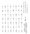
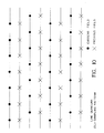
- the sampling frequency may be line-locked or subcarrier-locked, in either case resulting in a signal S that has been sampled on an orthogonal aligned three-dimensional (3D) sampling structure as illustrated in Figure 8.
- the digital signal (S) is applied to filtering and subsampling means 12, which filters and subsamples it to produce two distinct signals E and P, respectively.
- the two distinct signals E and P leave means 12 by different paths.
- the main (first), signal P comprises input pels obtained in the 2:1 subsampling means 56 ( Figure 3).
- Samples hereafter referred to as subsampled pels, are selected from the initial orthogonal structure in a systematic three-dimensional arrangement.
- the subsampled pels collectively referred to as the subsampling structure S PAT , are shown encircled in Figure 8 (by way of example). They are subsequently processed in the main channel (the associated signal path) by a DPCM encoder (to be described later).
- the complementary signal E which emerges on a different path, is derived by forming a difference between the input pels omitted in the subsampling means 56 (and not encircled in Figure 8) and their interpolated values.
- the interpolated values are obtained as a response of a multi-dimensional filter 50 to the input signal.
- a multi-dimensional filter 50 For general principles of operation of such a multi-dimensional filter, the reader is directed to the text by D.E. Dudgeon and R.M. Mersereau entitled “Multidimensional Digital Signal Processing", 1984, published by Prentice Hall Inc. Details of operation will be apparent from the examples provided.
- multi-dimensional filter 50 is of the interpolative kind, i.e. it operates on the subsampled pels only when producing a response for the omitted pels while leaving the subsampled pels intact, i.e. the filter response at the locations of subsampled pels is identical to the original values of those pels.
- Subtractor 52 provides the difference between the input signal S applied to the input of filter 50 and the interpolated values at the output of the filter 50.
- the difference signal furnished by subtractor 52 contains zeros in the subsampled-pel locations and non-zero interpolation error values in the remaining locations.
- the zeros are removed from signal E by the complementary subsampling means 54. Identical results are obtained if subsampling precedes interpolation and differencing as shown in the equivalent structure of Figure 7. It is an implementational concern that the multi-dimensional filter operates now on the subsampled pels only.
- signal E which constitutes interpolation error, passes through a quantizer 14, isolated pel suppressor 15, and variable word length (VWL) and block encoder 16 to emerge as signal E I coded at B I bits per second for application to multiplexer 18.
- VWL variable word length
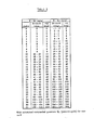
- Table 1 The code for the variable word length encoder is shown in Table 1, which is appended hereto.
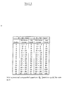
- Quantizer 14 is a uniform or mildly companded quantizer. It maps input decision ranges into output indices. For details of quantizer 14 see Table 4, which is appended hereto.
- the isolated pel suppressor 15 uses a sliding window to determine whether to set the current output of quantizer 14 to zero based on it being below a threshold and neighbouring indices on both sides of the current position being zero.
- the block encoder in means 16 segments the quantized interpolation error into two-dimensional blocks of N h x N v samples each. A constant overhead of 1 bit per block is assigned to indicate whether the block contains significant pels or insignificant pels. Only blocks containing at least one significant error are fed to the VWL coder.
- the DPCM encoder comprises subtractor 20, quantizer 22, inverse quantizer 24, adder 26, predictor 28 and a feedback loop 30 from the output of predictor 28 to the adder 26.
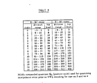
- the quantizer Q see Tables 2, 3 and 5, appended hereto.
- the operation of the DPCM coder is known per se and so will not be described in detail here. Typical construction and operation of such coders are described in U.S. patent number 2,605,361, issued July 1952 naming C.C. Cutler as inventor, the article by D.J. Connor et al mentioned above, and an article by H.G. Musmann, entitled “Predictive Image Coding", in Advances in Electronics and Electron Physics, Academic Press, Vol. Suppl. 12, pp. 73-112, 1979. The reader is directed to these documents for reference.
- the output E p of the DPCM coder, taken from quantizer 22, is applied to the multiplexer 18 at the rate of BS p bits per second.
- the output of the multiplexer is therefore a multiplexed signal with B I + B p bandwidth.
- the multiplexed signal presumably having passed through a transmission channel, is applied to a demultiplexer 34 separating it into two signals, E I and E p , corresponding to signals E I and E p , respectively, in the transmitter prior to multiplexing.
- E I and E p will be the same in both the transmitter and the receiver. Accordingly, and for simplicity, the same reference letters E I and E p have been used in both.
- the interpolation error signal E I is applied to VWL and block decoder means 36 and thence to inverse quantizer 38, which is the inverse of quantizer 14 in Figure 1.
- the output of the inverse quantizer 38 is the reconstituted interpolation error signal R E which is applied to an adder 40.
- R E interpolation error signal
- the reader is directed to the aforementioned disclosure by D.J. Connor et al.
- the second, predictive, signal E p is passed through a DPCM decoder comprising inverse quantizer 42, identical to the inverse quantizer 24 in Figure 1, adder 44, and predictor 46.
- the reconstituted signal R p indicated likewise in the transmitter in Figure 1, undergoes upconversion by zero insertion, then is applied to three-dimensional filtering and upconversion means 48. Upconversion is a reverse process to the subsampling process in that additional samples are inserted into the signal at the complementary pel locations.
- filtering and upconversion means 48 the upconverted signal is applied to a multi-dimensional filter corresponding to the multi-dimensional filter in the transmitter.
- the receiver filter leaves the subsampled pels unchanged while interpolating the inserted zero-valued samples.
- the output of the filter is supplied to adder 40 which adds the interpolation error R E to the interpolated samples only.
- the output of the adder 40 represents the reconstructed video signal for application to D/A converter 51.
- Embodiments of the invention can readily be configured for different bit rates of the input signal, types of signal and sampling rates. Examples of typical configurations follow:-
- the complementary path for coding signal E is based on the response of the multi-dimensional filter 50 operating on the input signal.
- the present invention encompasses another embodiment, to be considered a variation on that of Figure 1, which is shown in Figure 6.
- the previous arrangement is reconfigured such that the interpolative or complementary signal E is obtained by differencing the reconstructed R p signal with the output of filter 50, followed by complementary subsampling in means 54, which is part of the filtering and subsampling means 12.
- 2:1 subsampling means 56 is shown, in Figure 6, separate from means 12.
- the input signal S is applied directly to its input and its output provides the main signal P. Otherwise, the remaining processing is identical.
- a significant advantage of embodiments of the present invention is that the two channels can be used together to give a high quality signal using the total bandwidth.
- the coding deficiencies in the main or predictive path can be compensated for by the information supplied by the complementary path.
- the deficiencies of image quality in the main path arise from the information loss due to a 2:1 subsampling process.
- This process generally results in a loss of high spatio-temporal frequency content as well as an injection, known as aliasing, of high frequencies into low frequency areas. Aliasing generally appears as an interference pattern objectionable to the viewer.
- the complementary path preserves, to a large extent, the information lost during subsampling in the main path. Hence it carries a signal consisting mostly of the input signal's high spatio-temporal frequencies as well as an anti-alias signal, i.e., one which removes the alias signal embedded in the main path. It stands to reason that recombining the complementary channel with the main channel at the receiver has the effect of improving picture quality relative to that provided by the main channel alone.
- one channel may be used alone to give a signal of lesser quality using only a part of the total bandwidth. Moreover, the remaining bandwidth, released by the other signal, can be used for other purposes. It is particularly envisaged that one channel be capable of supplying CATV quality signals at 35 Mb/s, while the two together would be capable of broadcast quality at 45-47 Mb/s.
- the main channel carries information from which the input picture, albeit somewhat distorted, can be reconstructed. From the information carried in the complementary channel only the interpolation error can be reconstructed, which cannot reconstitute a picture.
- Figures 4 and 5 illustrate single-channel mode of operation, the unused components being shown with broken lines.
- Figure 4 which corresponds to the predictor channel of Figure 1
- every sample of signal S digitized in a similar manner as in Figure 1 is applied to optional multi-dimensional filter 58, and subsequently subsampled by means 56 according to a 2:1 sampling pattern S PAT producing signal P.
- the ensuing processing is identical to that in the predictive path in Figure 1, therefore its description will be omitted.
- the main simplification of the single-channel mode is that the interpolative path, and the multiplexer, are not used.
- Another difference is that the subsampled pels are subject to the bandlimiting effect of the multi-dimensional filter 58.
- the simplification consists in the non-use of the interpolative channel and demultiplexer.
- the predictive signal E p is reconstituted as signal R p in the same manner as in the predictive channel of the two-channel decoder ( Figure 2). Thence it is upconverted to a full resolution in a 2:1 zero insertion processor 47.
- the full resolution digitized image S R is reconstructed when the zero-valued inserted samples are interpolated by the digital filter 49. This signal is applied to D/A processor 50 to obain the analog video signal V at the output.
- the invention relates generally to video codecs employing multi-dimensional filters.
- sampling may cover one stage or more stages.
- Two-stage sampling and subsampling using means 10 and means 12 is preferred but a single stage of sampling could be done instead. Then A/D conversion would be employed in both cases - generation of the main signal and of the complementary signal.
Abstract
Description
- The invention relates to digital signal coding, and is applicable to coding of digitized colour video signals for storage and/or transmission. The invention is applicable especially, but not exclusively, to broadcast television signals in composite or component format.
- To transmit an uncoded broadcast quality colour NTSC television signal in digitized form requires a channel bandwidth of, typically, 90-130 Mb/s for the signal in the composite format and 216 Mb/s for the signal in the component format. These raw bit rates are based on the practice of quantizing the broadcast video signal with 8/9 bits, and sampling the composite NTSC signal at 4fsc = 14.3 MHz (four times the subcarrier frequency) and the component signal at 13.5 MHz in agreement with the CCIR recommendation 601. It is economically advantageous to reduce the channel bandwidth requirements substantially, especially to fit existing or proposed transmission standards in various countries. For example, reduced bit rates of 45, 90, and 135 Mb/s may be preferred, representing multiples of the DS3 bit rate within the North American hierarchy of digital transmission channels. In Europe, standard channel bit rates of 34 and 140 Mb/s, for example, are used.
- An object of the present invention is to provide a coding arrangement which gives high picture quality while being adaptable to different sampling rates and signal formats.
- According to the present invention, a coding arrangement provides from a digitized video signal two discrete digital signals, i.e. a main signal and a complementary signal, at the transmitter, with a different coding technique applied to each. The two signals may be multiplexed at the transmitter output for transmission, demultiplexed at the receiver input and recombined at the receiver output.
- An advantage of this coding arrangement is that the first or main signal can deliver a basic picture quality while its deficiencies can be compensated for at the receiver with the information contained in the second or complementary signal. The latter may, for example, be the interpolation error between the original values of pels (picture elements) dropped prior to transmission and their reconstructed values at the receiver.
- In a preferred embodiment, the first or main signal is subsampled and subjected to differential pulse code modulation (DPCM) coupled with fixed-rate companded quantization. The second or complementary signal is subjected to uniform quantization, variable word length (VWL) encoding and block encoding.
- If the optimum picture quality is needed, the two signals may be combined at the receiver. It is possible, however, to use only the first or main signal, with consequent bandwidth reduction, if some reduction of picture quality can be tolerated. For example, both signals might give a 45 Mb/s broadcast quality television signal, whereas the first or main signal alone might be suficient for CATV quality at 35 Mb/s. The bandwidth relinquished by omitting the second or complementary signal could be used for other purposes. Such an arrangement is of particular advantage for "bandwidth-on-demand" applications and also for transmission at bit rates complying with different hierarchical standards, enabling, for example, one coding scheme to satisfy North American, European and Japanese requirements.
- An embodiment of the invention will now be described by way of example only and with reference to the accompanying drawings, in which:
- Figure 1 is a block diagram of a two-channel encoder;
- Figure 2 is a block diagram of a matching decoder;
- Figure 3 shows a multi-dimensional filter and subsampler, which are part of the encoder;
- Figure 4 is a block diagram of the components involved in single channel operation of the encoder;
- Figure 5 is a corresponding block diagram of the matching decoder for single channel operation;
- Figure 6 is a block diagram of a modified two-channel encoder;
- Figure 7 shows the modified multi-dimensional filter and subsampler; and
- Figures 8, 9, 10 and 11 are the sampling pattern and subsampling patterns for signal processing the transmitter and receiver.
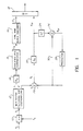
- Referring to Figure 1, apparatus for two-channel encoding of colour video signals, referred to herein as a transmitter, comprises an input terminal to which is applied a signal V to be encoded. The signal is digitized by an A/
D converter 10 wherein it is sampled with sampling frequency fs and amplitude accuracy BA. The sampling frequency may be line-locked or subcarrier-locked, in either case resulting in a signal S that has been sampled on an orthogonal aligned three-dimensional (3D) sampling structure as illustrated in Figure 8. The digital signal (S) is applied to filtering and subsampling means 12, which filters and subsamples it to produce two distinct signals E and P, respectively. The two distinct signals E and P leave means 12 by different paths. The main (first), signal P, comprises input pels obtained in the 2:1 subsampling means 56 (Figure 3). Samples, hereafter referred to as subsampled pels, are selected from the initial orthogonal structure in a systematic three-dimensional arrangement. The subsampled pels, collectively referred to as the subsampling structure SPAT, are shown encircled in Figure 8 (by way of example). They are subsequently processed in the main channel (the associated signal path) by a DPCM encoder (to be described later). - Referring to Figure 3, the complementary signal E, which emerges on a different path, is derived by forming a difference between the input pels omitted in the subsampling means 56 (and not encircled in Figure 8) and their interpolated values. The interpolated values are obtained as a response of a
multi-dimensional filter 50 to the input signal. For general principles of operation of such a multi-dimensional filter, the reader is directed to the text by D.E. Dudgeon and R.M. Mersereau entitled "Multidimensional Digital Signal Processing", 1984, published by Prentice Hall Inc. Details of operation will be apparent from the examples provided. - Referring again to Figure 3,
multi-dimensional filter 50 is of the interpolative kind, i.e. it operates on the subsampled pels only when producing a response for the omitted pels while leaving the subsampled pels intact, i.e. the filter response at the locations of subsampled pels is identical to the original values of those pels.Subtractor 52 provides the difference between the input signal S applied to the input offilter 50 and the interpolated values at the output of thefilter 50. The difference signal furnished bysubtractor 52 contains zeros in the subsampled-pel locations and non-zero interpolation error values in the remaining locations. The zeros are removed from signal E by the complementary subsampling means 54. Identical results are obtained if subsampling precedes interpolation and differencing as shown in the equivalent structure of Figure 7. It is an implementational concern that the multi-dimensional filter operates now on the subsampled pels only. - Referring again to Figure 1, signal E, which constitutes interpolation error, passes through a
quantizer 14, isolatedpel suppressor 15, and variable word length (VWL) andblock encoder 16 to emerge as signal EI coded at BI bits per second for application to multiplexer 18. The code for the variable word length encoder is shown in Table 1, which is appended hereto. For details of the construction and operation of such a VWL encoder the reader is referred to U.S. patent application serial number 551,145, filed November 14, 1983, naming O. Bahgat as inventor. - Quantizer 14 is a uniform or mildly companded quantizer. It maps input decision ranges into output indices. For details of
quantizer 14 see Table 4, which is appended hereto. Theisolated pel suppressor 15 uses a sliding window to determine whether to set the current output ofquantizer 14 to zero based on it being below a threshold and neighbouring indices on both sides of the current position being zero. The block encoder inmeans 16 segments the quantized interpolation error into two-dimensional blocks of Nh x Nv samples each. A constant overhead of 1 bit per block is assigned to indicate whether the block contains significant pels or insignificant pels. Only blocks containing at least one significant error are fed to the VWL coder. Construction and operation of a suitable block encoder are well-known and are disclosed, for example, by D.J. Connor, R.F.W. Peace and W.G. Scholes, in "Television Coding Using Two-Dimensional Spatial Prediction", Bell System Technical Journal, Vol. 50, No. 3, pp 1049-1061, March 1971 to which the reader is directed for reference. - As mentioned previously, signal P passes through the differential pulse code modulation (DPCM) encoder in reaching
multiplexer 18. As shown in Figure 4, the DPCM encoder comprisessubtractor 20,quantizer 22,inverse quantizer 24,adder 26,predictor 28 and afeedback loop 30 from the output ofpredictor 28 to theadder 26. For details of the quantizer Q, see Tables 2, 3 and 5, appended hereto. The operation of the DPCM coder is known per se and so will not be described in detail here. Typical construction and operation of such coders are described in U.S. patent number 2,605,361, issued July 1952 naming C.C. Cutler as inventor, the article by D.J. Connor et al mentioned above, and an article by H.G. Musmann, entitled "Predictive Image Coding", in Advances in Electronics and Electron Physics, Academic Press, Vol. Suppl. 12, pp. 73-112, 1979. The reader is directed to these documents for reference. - The output Ep of the DPCM coder, taken from
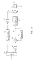
quantizer 22, is applied to themultiplexer 18 at the rate of BSp bits per second. The output of the multiplexer is therefore a multiplexed signal with BI + Bp bandwidth. - Referring to Figure 2, which is the block diagram of the receiver or decoder, the multiplexed signal, presumably having passed through a transmission channel, is applied to a
demultiplexer 34 separating it into two signals, EI and Ep, corresponding to signals EI and Ep, respectively, in the transmitter prior to multiplexing. In the case of error-free transmission, EI and Ep will be the same in both the transmitter and the receiver. Accordingly, and for simplicity, the same reference letters EI and Ep have been used in both. The interpolation error signal EI is applied to VWL and block decoder means 36 and thence toinverse quantizer 38, which is the inverse ofquantizer 14 in Figure 1. The output of theinverse quantizer 38 is the reconstituted interpolation error signal RE which is applied to anadder 40. For details of the construction and operation of a suitable VWL decoder the reader is directed to U.S. patent number 551,087, issued November 14, 1985, naming O. Bahgat as inventor. For details of the construction and operation of a suitable block decoder, the reader is directed to the aforementioned disclosure by D.J. Connor et al. - The second, predictive, signal Ep is passed through a DPCM decoder comprising
inverse quantizer 42, identical to theinverse quantizer 24 in Figure 1,adder 44, andpredictor 46. The reconstituted signal Rp, indicated likewise in the transmitter in Figure 1, undergoes upconversion by zero insertion, then is applied to three-dimensional filtering and upconversion means 48. Upconversion is a reverse process to the subsampling process in that additional samples are inserted into the signal at the complementary pel locations. In filtering and upconversion means 48, the upconverted signal is applied to a multi-dimensional filter corresponding to the multi-dimensional filter in the transmitter. The receiver filter leaves the subsampled pels unchanged while interpolating the inserted zero-valued samples. The output of the filter is supplied to adder 40 which adds the interpolation error RE to the interpolated samples only. The output of theadder 40 represents the reconstructed video signal for application to D/A converter 51. - Embodiments of the invention can readily be configured for different bit rates of the input signal, types of signal and sampling rates. Examples of typical configurations follow:-


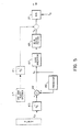
- In the embodiment of the invention depicted in Figure 1 the complementary path for coding signal E is based on the response of the
multi-dimensional filter 50 operating on the input signal. The present invention encompasses another embodiment, to be considered a variation on that of Figure 1, which is shown in Figure 6. The previous arrangement is reconfigured such that the interpolative or complementary signal E is obtained by differencing the reconstructed Rp signal with the output offilter 50, followed by complementary subsampling inmeans 54, which is part of the filtering and subsampling means 12. 2:1 subsampling means 56 is shown, in Figure 6, separate frommeans 12. The input signal S is applied directly to its input and its output provides the main signal P. Otherwise, the remaining processing is identical. - A significant advantage of embodiments of the present invention is that the two channels can be used together to give a high quality signal using the total bandwidth. The coding deficiencies in the main or predictive path can be compensated for by the information supplied by the complementary path.
- More particularly, the deficiencies of image quality in the main path arise from the information loss due to a 2:1 subsampling process. This process generally results in a loss of high spatio-temporal frequency content as well as an injection, known as aliasing, of high frequencies into low frequency areas. Aliasing generally appears as an interference pattern objectionable to the viewer. The complementary path preserves, to a large extent, the information lost during subsampling in the main path. Hence it carries a signal consisting mostly of the input signal's high spatio-temporal frequencies as well as an anti-alias signal, i.e., one which removes the alias signal embedded in the main path. It stands to reason that recombining the complementary channel with the main channel at the receiver has the effect of improving picture quality relative to that provided by the main channel alone.
- Advantageously, one channel may be used alone to give a signal of lesser quality using only a part of the total bandwidth. Moreover, the remaining bandwidth, released by the other signal, can be used for other purposes. It is particularly envisaged that one channel be capable of supplying CATV quality signals at 35 Mb/s, while the two together would be capable of broadcast quality at 45-47 Mb/s. The main channel carries information from which the input picture, albeit somewhat distorted, can be reconstructed. From the information carried in the complementary channel only the interpolation error can be reconstructed, which cannot reconstitute a picture.
- Figures 4 and 5 illustrate single-channel mode of operation, the unused components being shown with broken lines. Referring to Figure 4, which corresponds to the predictor channel of Figure 1, every sample of signal S, digitized in a similar manner as in Figure 1, is applied to optional
multi-dimensional filter 58, and subsequently subsampled by means 56 according to a 2:1 sampling pattern SPAT producing signalP. Leaving filter 58 out effects a gain in apparatus simplicity at the expense of some picture quality loss due to signal alias introduced in the subsampling process. The ensuing processing is identical to that in the predictive path in Figure 1, therefore its description will be omitted. The main simplification of the single-channel mode is that the interpolative path, and the multiplexer, are not used. Another difference is that the subsampled pels are subject to the bandlimiting effect of themulti-dimensional filter 58. - In the single-channel decoder, shown in Figure 5, the simplification consists in the non-use of the interpolative channel and demultiplexer. The predictive signal Ep is reconstituted as signal Rp in the same manner as in the predictive channel of the two-channel decoder (Figure 2). Thence it is upconverted to a full resolution in a 2:1 zero
insertion processor 47. The full resolution digitized image SR is reconstructed when the zero-valued inserted samples are interpolated by thedigital filter 49. This signal is applied to D/A processor 50 to obain the analog video signal V at the output. - Although the specific embodiments refer to a three-dimensional filter, the invention relates generally to video codecs employing multi-dimensional filters.
- In this specification, the term "sampling" may cover one stage or more stages.
- Two-stage sampling and subsampling using means 10 and means 12 is preferred but a single stage of sampling could be done instead. Then A/D conversion would be employed in both cases - generation of the main signal and of the complementary signal.
Claims (84)
means (12) for providing two distinct signals (E,P), one of said two distinct signals (P) corresponding to said digital signal (S) and the other (E) of said two distinct signals (E,P) corresponding to the difference between said digital signal (S) and a filtered signal derived by filtering said digital signal (S) or its reconstructed signal (Rp); and
first and second coding means (14,15,16;20,22,24,26,28,30) for encoding said two distinct signals (E,P) to provide two coded distinct signals (EI, Ep), respectively, each of said first and second coding means being operative to encode in a different way to that in which the other encodes.
multi-dimensional filter means (50) responsive to said signal (S) for producing a filtered signal,
subtractor means (52) for differencing said signal (S) and the filtered signal to provide an interpolation error signal (I), and
complementary subsampling means (54) responsive to the output of the subtractor means (52) to provide said other (E) of said two distinct signals.


providing two distinct signals, (E,P) one of said two distinct signals (P) corresponding to said digital signal (S) and the other (E) of said two distinct signals (E,P) corresponding to the difference between said digital signal (S) and a filtered signal derived by filtering said digital signal (S) or by filtering its reconstructed signal (Rp); and
encoding said two distinct signals (E,P) to provide two encoded distinct signals (Ep, EI), each of said two encoded distinct signals (Ep, EI) being encoded differently from the other of said two encoded distinct signals.
employing multi-dimensional filter means to produce from said signal (S) a filtered signal,
differencing said signal (S) and said filtered signal to provide an interpolated signal (I), and
complementary subsampling said interpolated signal (I) to provide said one (E) of said two distinct signals.


said decoder comprising first and second decoding means (36,38;42,44,46) having inverse characteristics of said first and second coding means, respectively, for providing two decoded distinct signals (RE, Rp), respectively.
said decoder comprises a single decoding means (42, 44, 46) for providing only a decoded signal Rp corresponding to said one of said two distant signals (E,P).
wherein said decoder further comprises filtering and upconversion means (48) for filtering and upconverting the output (Rp) of said second or single decoding means (42,44,46).


wherein said filtering and upconversion means (48) in said decoder includes a filter having the response:-

providing two distinct signals (E,P), one (P) of said two distinct signals corresponding to a digital signal (S) and the other (E) of said two distinct signals corresponding to the difference between said digital signal (S) and a filtered signal derived by filtering said digital signal (S) or by filtering its reconstructed signal (Rp) and
encoding each of said two distinct signals differently from the other of said two distinct signals;
said decoding comprising the steps of decoding each of the encoded distinct signals (EI, Ep) in different ways each corresponding inversely to the encoding step in said encoder to provide two decoded signal (RE, Rp) corresponding respectively to said two distinct signals (E,P) and applying said one (Rp) of said two decoded distinct signals (RE, Rp) to a filter to provide a corresponding digital signal (SR).
providing two distinct signals (E,P), one (P) of said two distinct signals corresponding to a digital signal (S) and the other (E) of said two distinct signals corresponding to the difference between said digital signal (S) and a filtered signal derived by filtering said digital signal (S) or by filtering its reconstructed signal (Rp) and encoding said one (P) of said two distinct signals (E,P) differently from said other (E) of said two distinct signals in providing two corresponding encoded distinct signals (EI, Ep);
said decoding comprising the step of decoding only said one (Ep) of said two encoded distinct signals to generate a decoded signal (Rp).
subsampling said digital signal (S) to provide a first subsampled signal as said one (P) of said two distinct signals, and filtering and subsampling said digital signal (S) to provide a complementary subsampled signal (E) as said other of said two distinct signals;
said method of decoding comprising the step of filtering and upconverting said regenerated said decoded one (Rp) of said two decoded distinct signals (RE, Rp).


Priority Applications (1)
| Application Number | Priority Date | Filing Date | Title |
|---|---|---|---|
| AT87310736T ATE95365T1 (en) | 1986-12-08 | 1987-12-07 | DIGITAL SIGNAL CODING IN TWO CODING CHANNELS. |
Applications Claiming Priority (2)
| Application Number | Priority Date | Filing Date | Title |
|---|---|---|---|
| CA000524786A CA1261069A (en) | 1986-12-08 | 1986-12-08 | Two-channel coding of digital signals |
| CA524786 | 1986-12-08 |
Publications (3)
| Publication Number | Publication Date |
|---|---|
| EP0274861A2 true EP0274861A2 (en) | 1988-07-20 |
| EP0274861A3 EP0274861A3 (en) | 1990-12-27 |
| EP0274861B1 EP0274861B1 (en) | 1993-09-29 |
Family
ID=4134507
Family Applications (1)
| Application Number | Title | Priority Date | Filing Date |
|---|---|---|---|
| EP87310736A Expired - Lifetime EP0274861B1 (en) | 1986-12-08 | 1987-12-07 | Two-channel coding of digital signals |
Country Status (10)
| Country | Link |
|---|---|
| US (1) | US4782387A (en) |
| EP (1) | EP0274861B1 (en) |
| JP (2) | JPS63152237A (en) |
| KR (1) | KR880008676A (en) |
| CN (1) | CN1011467B (en) |
| AT (1) | ATE95365T1 (en) |
| AU (1) | AU596717B2 (en) |
| BR (1) | BR8706607A (en) |
| CA (1) | CA1261069A (en) |
| DE (1) | DE3787637T2 (en) |
Cited By (5)
| Publication number | Priority date | Publication date | Assignee | Title |
|---|---|---|---|---|
| GB2240448A (en) * | 1989-12-04 | 1991-07-31 | Ricoh Kk | "High quality color image compression system" |
| EP0448491A1 (en) * | 1990-03-23 | 1991-09-25 | France Telecom | Method of coding and transmitting digital images of an image sequence with at least two quality levels and corresponding devices |
| WO1995002303A1 (en) * | 1993-07-07 | 1995-01-19 | Rca Thomson Licensing Corporation | Method and apparatus for providing scaleable compressed video signal |
| EP1133166A2 (en) * | 2000-01-06 | 2001-09-12 | Hewlett-Packard Company, A Delaware Corporation | Using hardware to double the X-dimension in a video frame |
| EP1846922A2 (en) * | 2005-02-03 | 2007-10-24 | Pitney Bowes, Inc. | Method for two-channel coding of a message |
Families Citing this family (28)
| Publication number | Priority date | Publication date | Assignee | Title |
|---|---|---|---|---|
| US4965825A (en) * | 1981-11-03 | 1990-10-23 | The Personalized Mass Media Corporation | Signal processing apparatus and methods |
| US7831204B1 (en) | 1981-11-03 | 2010-11-09 | Personalized Media Communications, Llc | Signal processing apparatus and methods |
| USRE47642E1 (en) | 1981-11-03 | 2019-10-08 | Personalized Media Communications LLC | Signal processing apparatus and methods |
| FR2613166B1 (en) * | 1987-03-24 | 1989-06-23 | Labo Electronique Physique | DEVICE FOR TRANSMITTING HIGH DEFINITION IMAGES THROUGH A RELATIVELY NARROW BANDPASS CHANNEL |
| FR2613165B1 (en) * | 1987-03-24 | 1989-06-23 | Labo Electronique Physique | HIGH DEFINITION TELEVISION IMAGE TRANSMISSION SYSTEM THROUGH A NARROW BANDPASS CHANNEL |
| JP2829954B2 (en) * | 1987-08-22 | 1998-12-02 | ソニー株式会社 | Apparatus and method for highly efficient encoding of image signal |
| JPS6477391A (en) * | 1987-09-18 | 1989-03-23 | Victor Company Of Japan | System and device for predictive coding |
| JPH01181395A (en) * | 1988-01-14 | 1989-07-19 | Canon Inc | Video signal coder |
| US5016100A (en) * | 1988-04-04 | 1991-05-14 | Zenith Electronics Corporation | Transmission of a video signal using adaptive delta modulation |
| JPH02224488A (en) * | 1989-02-27 | 1990-09-06 | Canon Inc | Picture transmission system |
| JP2925157B2 (en) * | 1989-02-28 | 1999-07-28 | キヤノン株式会社 | Data storage device |
| US5128758A (en) * | 1989-06-02 | 1992-07-07 | North American Philips Corporation | Method and apparatus for digitally processing a high definition television augmentation signal |
| US5179442A (en) * | 1989-06-02 | 1993-01-12 | North American Philips Corporation | Method and apparatus for digitally processing a high definition television augmentation signal |
| US4958226A (en) * | 1989-09-27 | 1990-09-18 | At&T Bell Laboratories | Conditional motion compensated interpolation of digital motion video |
| EP0436251B1 (en) * | 1989-12-29 | 1995-09-27 | Laboratoires D'electronique Philips | Coder/decoder for digital signals to be transmitted and/or stored |
| US5067016A (en) * | 1990-03-07 | 1991-11-19 | Industrial Technology Research Institute | Progressive scan system with field-offset sampling |
| JP2722353B2 (en) * | 1990-04-26 | 1998-03-04 | キヤノン株式会社 | Image signal encoding device |
| US5010402A (en) * | 1990-05-17 | 1991-04-23 | Matsushita Electric Industrial Co., Ltd. | Video signal compression apparatus |
| US5057917A (en) * | 1990-06-20 | 1991-10-15 | The United States Of America As Represented By The Administrator Of The National Aeronautics And Space Administration | Real-time data compression of broadcast video signals |
| GB2245805A (en) * | 1990-06-29 | 1992-01-08 | Philips Electronic Associated | Generating an anti-aliased image |
| JPH04204594A (en) * | 1990-11-30 | 1992-07-24 | Canon Inc | High-precision display device |
| JP2606508B2 (en) * | 1991-10-29 | 1997-05-07 | 日本ビクター株式会社 | Video prediction encoding apparatus and decoding apparatus therefor |
| JP2830883B2 (en) * | 1991-10-31 | 1998-12-02 | 日本ビクター株式会社 | Video encoding device and decoding device therefor |
| US5280343A (en) * | 1992-01-21 | 1994-01-18 | Eastman Kodak Company | Separable subsampling of digital image data with general periodic symmetry |
| US5337085A (en) * | 1992-04-10 | 1994-08-09 | Comsat Corporation | Coding technique for high definition television signals |
| US6307597B1 (en) * | 1996-03-07 | 2001-10-23 | Thomson Licensing S.A. | Apparatus for sampling and displaying an auxiliary image with a main image |
| US8331445B2 (en) * | 2004-06-01 | 2012-12-11 | Qualcomm Incorporated | Method, apparatus, and system for enhancing robustness of predictive video codecs using a side-channel based on distributed source coding techniques |
| US9717440B2 (en) * | 2013-05-03 | 2017-08-01 | The Florida International University Board Of Trustees | Systems and methods for decoding intended motor commands from recorded neural signals for the control of external devices or to interact in virtual environments |
Citations (2)
| Publication number | Priority date | Publication date | Assignee | Title |
|---|---|---|---|---|
| EP0180345A2 (en) * | 1984-10-04 | 1986-05-07 | Nec Corporation | Method and apparatus for picture signal encoding and decoding |
| US4665436A (en) * | 1985-12-20 | 1987-05-12 | Osborne Joseph A | Narrow bandwidth signal transmission |
Family Cites Families (10)
| Publication number | Priority date | Publication date | Assignee | Title |
|---|---|---|---|---|
| US2605361A (en) * | 1950-06-29 | 1952-07-29 | Bell Telephone Labor Inc | Differential quantization of communication signals |
| US2905756A (en) * | 1956-11-30 | 1959-09-22 | Bell Telephone Labor Inc | Method and apparatus for reducing television bandwidth |
| US4700361A (en) * | 1983-10-07 | 1987-10-13 | Dolby Laboratories Licensing Corporation | Spectral emphasis and de-emphasis |
| US4580129A (en) * | 1983-11-14 | 1986-04-01 | Northern Telecom Limited | Variable word length decoder |
| US4568916A (en) * | 1983-11-14 | 1986-02-04 | Bahgat Osama A E H | Variable word length encoder |
| DE3412986A1 (en) * | 1984-04-06 | 1985-10-24 | Standard Elektrik Lorenz Ag, 7000 Stuttgart | DIGITAL MESSAGE TRANSMISSION SYSTEM WITH INTEGRATED TRANSMISSION OF ADDITIONAL INFORMATION WITH A LOW BIT SEQUENCE FREQUENCY |
| US4661862A (en) * | 1984-04-27 | 1987-04-28 | Rca Corporation | Differential PCM video transmission system employing horizontally offset five pixel groups and delta signals having plural non-linear encoding functions |
| JPS60237738A (en) * | 1984-05-11 | 1985-11-26 | Sony Corp | Digital signal transmission device |
| AU4431485A (en) * | 1984-06-09 | 1986-01-10 | Devon County Council | Data communication method and apparatus |
| JPS6162286A (en) * | 1984-09-04 | 1986-03-31 | Univ Nagoya | Picture signal band compressing system |
-
1986
- 1986-12-08 CA CA000524786A patent/CA1261069A/en not_active Expired
- 1986-12-09 US US06/939,983 patent/US4782387A/en not_active Expired - Lifetime
-
1987
- 1987-12-03 JP JP62304665A patent/JPS63152237A/en active Pending
- 1987-12-07 KR KR870013904A patent/KR880008676A/en not_active Application Discontinuation
- 1987-12-07 AT AT87310736T patent/ATE95365T1/en not_active IP Right Cessation
- 1987-12-07 EP EP87310736A patent/EP0274861B1/en not_active Expired - Lifetime
- 1987-12-07 DE DE87310736T patent/DE3787637T2/en not_active Expired - Fee Related
- 1987-12-07 AU AU82185/87A patent/AU596717B2/en not_active Ceased
- 1987-12-08 JP JP62308847A patent/JPH0656982B2/en not_active Expired - Fee Related
- 1987-12-08 CN CN87107425A patent/CN1011467B/en not_active Expired
- 1987-12-08 BR BR8706607A patent/BR8706607A/en unknown
Patent Citations (2)
| Publication number | Priority date | Publication date | Assignee | Title |
|---|---|---|---|---|
| EP0180345A2 (en) * | 1984-10-04 | 1986-05-07 | Nec Corporation | Method and apparatus for picture signal encoding and decoding |
| US4665436A (en) * | 1985-12-20 | 1987-05-12 | Osborne Joseph A | Narrow bandwidth signal transmission |
Cited By (9)
| Publication number | Priority date | Publication date | Assignee | Title |
|---|---|---|---|---|
| GB2240448A (en) * | 1989-12-04 | 1991-07-31 | Ricoh Kk | "High quality color image compression system" |
| GB2240448B (en) * | 1989-12-04 | 1994-06-22 | Ricoh Kk | High quality color image compression system |
| EP0448491A1 (en) * | 1990-03-23 | 1991-09-25 | France Telecom | Method of coding and transmitting digital images of an image sequence with at least two quality levels and corresponding devices |
| FR2660139A1 (en) * | 1990-03-23 | 1991-09-27 | France Etat | METHOD OF ENCODING AND TRANSMITTING AT AT LEAST TWO QUALITY LEVELS OF DIGITAL IMAGES BELONGING TO A SEQUENCE OF IMAGES, AND CORRESPONDING DEVICES THEREOF. |
| WO1995002303A1 (en) * | 1993-07-07 | 1995-01-19 | Rca Thomson Licensing Corporation | Method and apparatus for providing scaleable compressed video signal |
| EP1133166A2 (en) * | 2000-01-06 | 2001-09-12 | Hewlett-Packard Company, A Delaware Corporation | Using hardware to double the X-dimension in a video frame |
| EP1133166A3 (en) * | 2000-01-06 | 2003-08-06 | Hewlett-Packard Company, A Delaware Corporation | Using hardware to double the X-dimension in a video frame |
| EP1846922A2 (en) * | 2005-02-03 | 2007-10-24 | Pitney Bowes, Inc. | Method for two-channel coding of a message |
| EP1846922A4 (en) * | 2005-02-03 | 2009-04-08 | Pitney Bowes Inc | Method for two-channel coding of a message |
Also Published As
| Publication number | Publication date |
|---|---|
| JPH0656982B2 (en) | 1994-07-27 |
| BR8706607A (en) | 1988-07-19 |
| AU8218587A (en) | 1988-06-16 |
| DE3787637T2 (en) | 1994-01-27 |
| EP0274861A3 (en) | 1990-12-27 |
| KR880008676A (en) | 1988-08-31 |
| AU596717B2 (en) | 1990-05-10 |
| CA1261069A (en) | 1989-09-26 |
| CN87107425A (en) | 1988-11-23 |
| US4782387A (en) | 1988-11-01 |
| ATE95365T1 (en) | 1993-10-15 |
| CN1011467B (en) | 1991-01-30 |
| EP0274861B1 (en) | 1993-09-29 |
| DE3787637D1 (en) | 1993-11-04 |
| JPS63191429A (en) | 1988-08-08 |
| JPS63152237A (en) | 1988-06-24 |
Similar Documents
| Publication | Publication Date | Title |
|---|---|---|
| EP0274861B1 (en) | Two-channel coding of digital signals | |
| US4827336A (en) | Symbol code generation processing from interframe DPCM of TDM'd spatial-frequency analyses of video signals | |
| US5253058A (en) | Efficient coding scheme for multilevel video transmission | |
| DE69535228T2 (en) | Image conversion device | |
| EP0682454B1 (en) | Method and apparatus for transcoding bitstreams of videodata | |
| US5128758A (en) | Method and apparatus for digitally processing a high definition television augmentation signal | |
| JPH10503895A (en) | Video compression | |
| EP0618729B1 (en) | Video-signal transmitting and receiving apparatus and method thereof | |
| JP2542025B2 (en) | System including an apparatus for encoding a broadcast quality television signal enabling transmission as an embedded code and an apparatus for decoding the encoded signal | |
| JPH06225285A (en) | System provided with at least one coder for coding digital signal and at least one decoder for decoding digital signal and coder and decoder for use in such system | |
| US5850261A (en) | Efficient variable length encoder and decoder | |
| Murakami et al. | 15/30 Mbit/s universal digital TV codec using a median adaptive predictive coding method | |
| US4941042A (en) | Television transmission system including a hybrid encoding circuit | |
| EP0618727B1 (en) | Encoder and decoder | |
| JP2000511722A (en) | Improvements for changing the bit rate of the signal | |
| CA1304152C (en) | System for adaptively generating signal in alternate formats as for an edtv system | |
| Kinuhata et al. | Universal digital TV codec—unicodec | |
| Sabri et al. | Coding of broadcast TV signals for transmission over satellite channels | |
| KR0159293B1 (en) | Subband vector quantization method | |
| Musmann | Digital coding of television signals | |
| Wells | Component codec standards for high-quality digital television | |
| Koga et al. | Low bit rate motion video coder/decoder for teleconferencing | |
| Wells | Component codecs for digital television transmission | |
| Netravali | IMAGE PROCESSING FOR COMMUNICATION | |
| JPH0260386A (en) | Narrow-band multiple subsample transmission system |
Legal Events
| Date | Code | Title | Description |
|---|---|---|---|
| PUAI | Public reference made under article 153(3) epc to a published international application that has entered the european phase |
Free format text: ORIGINAL CODE: 0009012 |
|
| AK | Designated contracting states |
Kind code of ref document: A2 Designated state(s): AT DE FR GB IT NL SE |
|
| PUAL | Search report despatched |
Free format text: ORIGINAL CODE: 0009013 |
|
| AK | Designated contracting states |
Kind code of ref document: A3 Designated state(s): AT DE FR GB IT NL SE |
|
| 17P | Request for examination filed |
Effective date: 19910605 |
|
| 17Q | First examination report despatched |
Effective date: 19930203 |
|
| GRAA | (expected) grant |
Free format text: ORIGINAL CODE: 0009210 |
|
| AK | Designated contracting states |
Kind code of ref document: B1 Designated state(s): AT DE FR GB IT NL SE |
|
| PG25 | Lapsed in a contracting state [announced via postgrant information from national office to epo] |
Ref country code: IT Free format text: LAPSE BECAUSE OF FAILURE TO SUBMIT A TRANSLATION OF THE DESCRIPTION OR TO PAY THE FEE WITHIN THE PRE;WARNING: LAPSES OF ITALIAN PATENTS WITH EFFECTIVE DATE BEFORE 2007 MAY HAVE OCCURRED AT ANY TIME BEFORE 2007. THE CORRECT EFFECTIVE DATE MAY BE DIFFERENT FROM THE ONE RECORDED.SCRIBED TIME-LIMIT Effective date: 19930929 Ref country code: FR Effective date: 19930929 Ref country code: NL Effective date: 19930929 Ref country code: AT Effective date: 19930929 Ref country code: SE Effective date: 19930929 |
|
| REF | Corresponds to: |
Ref document number: 95365 Country of ref document: AT Date of ref document: 19931015 Kind code of ref document: T |
|
| REF | Corresponds to: |
Ref document number: 3787637 Country of ref document: DE Date of ref document: 19931104 |
|
| EN | Fr: translation not filed | ||
| NLV1 | Nl: lapsed or annulled due to failure to fulfill the requirements of art. 29p and 29m of the patents act | ||
| PLBE | No opposition filed within time limit |
Free format text: ORIGINAL CODE: 0009261 |
|
| STAA | Information on the status of an ep patent application or granted ep patent |
Free format text: STATUS: NO OPPOSITION FILED WITHIN TIME LIMIT |
|
| 26N | No opposition filed | ||
| REG | Reference to a national code |
Ref country code: GB Ref legal event code: IF02 |
|
| PGFP | Annual fee paid to national office [announced via postgrant information from national office to epo] |
Ref country code: GB Payment date: 20031124 Year of fee payment: 17 |
|
| PGFP | Annual fee paid to national office [announced via postgrant information from national office to epo] |
Ref country code: DE Payment date: 20031230 Year of fee payment: 17 |
|
| PG25 | Lapsed in a contracting state [announced via postgrant information from national office to epo] |
Ref country code: GB Free format text: LAPSE BECAUSE OF NON-PAYMENT OF DUE FEES Effective date: 20041207 |
|
| PG25 | Lapsed in a contracting state [announced via postgrant information from national office to epo] |
Ref country code: DE Free format text: LAPSE BECAUSE OF NON-PAYMENT OF DUE FEES Effective date: 20050701 |
|
| GBPC | Gb: european patent ceased through non-payment of renewal fee |
Effective date: 20041207 |