EP0277258A1 - Device for transporting and accumulating pallets - Google Patents
Device for transporting and accumulating pallets Download PDFInfo
- Publication number
- EP0277258A1 EP0277258A1 EP87101561A EP87101561A EP0277258A1 EP 0277258 A1 EP0277258 A1 EP 0277258A1 EP 87101561 A EP87101561 A EP 87101561A EP 87101561 A EP87101561 A EP 87101561A EP 0277258 A1 EP0277258 A1 EP 0277258A1
- Authority
- EP
- European Patent Office
- Prior art keywords
- conveyor
- rollers
- roller
- holder
- accumulation
- Prior art date
- Legal status (The legal status is an assumption and is not a legal conclusion. Google has not performed a legal analysis and makes no representation as to the accuracy of the status listed.)
- Granted
Links
Images

Classifications
-
- B—PERFORMING OPERATIONS; TRANSPORTING
- B65—CONVEYING; PACKING; STORING; HANDLING THIN OR FILAMENTARY MATERIAL
- B65G—TRANSPORT OR STORAGE DEVICES, e.g. CONVEYORS FOR LOADING OR TIPPING, SHOP CONVEYOR SYSTEMS OR PNEUMATIC TUBE CONVEYORS
- B65G47/00—Article or material-handling devices associated with conveyors; Methods employing such devices
- B65G47/22—Devices influencing the relative position or the attitude of articles during transit by conveyors
- B65G47/26—Devices influencing the relative position or the attitude of articles during transit by conveyors arranging the articles, e.g. varying spacing between individual articles
- B65G47/261—Accumulating articles
- B65G47/268—Accumulating articles by means of belt or chain conveyor
-
- B—PERFORMING OPERATIONS; TRANSPORTING
- B65—CONVEYING; PACKING; STORING; HANDLING THIN OR FILAMENTARY MATERIAL
- B65G—TRANSPORT OR STORAGE DEVICES, e.g. CONVEYORS FOR LOADING OR TIPPING, SHOP CONVEYOR SYSTEMS OR PNEUMATIC TUBE CONVEYORS
- B65G17/00—Conveyors having an endless traction element, e.g. a chain, transmitting movement to a continuous or substantially-continuous load-carrying surface or to a series of individual load-carriers; Endless-chain conveyors in which the chains form the load-carrying surface
- B65G17/24—Conveyors having an endless traction element, e.g. a chain, transmitting movement to a continuous or substantially-continuous load-carrying surface or to a series of individual load-carriers; Endless-chain conveyors in which the chains form the load-carrying surface comprising a series of rollers which are moved, e.g. over a supporting surface, by the traction element to effect conveyance of loads or load-carriers
-
- B—PERFORMING OPERATIONS; TRANSPORTING
- B65—CONVEYING; PACKING; STORING; HANDLING THIN OR FILAMENTARY MATERIAL
- B65G—TRANSPORT OR STORAGE DEVICES, e.g. CONVEYORS FOR LOADING OR TIPPING, SHOP CONVEYOR SYSTEMS OR PNEUMATIC TUBE CONVEYORS
- B65G2201/00—Indexing codes relating to handling devices, e.g. conveyors, characterised by the type of product or load being conveyed or handled
- B65G2201/02—Articles
Definitions
- the invention relates to a method for transporting and stowing pallets with guide and accumulation rollers arranged on a pulling element on an axis.
- roller chains or carrier chain conveyors Furthermore, with such accumulation roller chains or carrier chain conveyors, a polygon effect will occur when the conveyor chain rotates around the drive wheel or the deflection wheel, which leads to wear of the drive or deflection wheel. Furthermore, roller chains of this type both have to absorb the weight of the transported object and also to take over the tensile force. This increases the wear of such roller chains.
- roller chains of this type are put together by arranging them parallel to conveyor tracks and accumulating roller conveyors, considerable effort is inevitable with regard to the synchronism between the two chains running in parallel. Also, due to the wear that occurs, alignment of the support elements with the tension elements is only possible with additional wear.
- the invention is based on the object, in such conveyors which are used for the transport of pallets and large objects, to reduce maintenance and wear substantially, to reduce the noise level by the conveyor system and at the same time start-up and braking impacts on the material to be conveyed to avoid with a safe parallel guidance of such a pair of conveyors.
- This object is achieved by the characterizing features of claim 1. Due to the elastic guidance of the carrying and storage rollers from the traction element and their elastic Centering to the traction element a straight run is achieved, so that no wear can occur due to a skewing of the support roller or the accumulation roller to the traction element.
- the object on which the invention is based is achieved with the characterizing features of claim 2. Due to the axle holder attached to a conveyor belt, which is arranged in particular by means of gluing on the upper side of the conveyor belt and the arrangement of a roller holder that carries the accumulation roller and idler rollers and that follows the axle holder, the side walls of the roller holder as holding struts for the roller holder itself being rotatable with the axle holder by means of bolts are connected, a clear centering of the idler rollers and the accumulation rollers to the conveyor belt is achieved due to the roller holder overrunning to the axle holder.
- the conveyor belt itself is an endless rubber belt reinforced with steel cables or a rubber or plastic belt reinforced with glass fiber cables; textile or polyamide fabrics can also be used as reinforcements.
- a conveying device is protected, with which the object on which the invention is based is also achieved when the conveying member is reversed, that is to say when the conveying direction is reversed.
- Elastic side walls which can consist of plastic-coated resilient steel cheeks, or which can consist of elastic reinforced plastics, which are each rotatably connected to the axle brackets, are due to the constructive design of the side walls, which are at an obtuse angle in the area of Axis, the idler rollers and the accumulation roller meet and which are preferably in one piece, the stresses occurring due to the rotation around drive or deflection wheels due to elongation of the conveyor belt without any wear of metallic components.
- the idler rollers or the accumulation rollers themselves serve as rolling supports. This results in a considerable reduction in the friction in the returning run of the conveyor belt according to the invention.
- the protection of the subject matter of the invention proposed in claim 6 suggests arranging guide blocks on the roll holder. This is of particular advantage when accumulation rollers and idler rollers of large width are connected according to the invention with a narrow conveyor belt and when the idler rollers are guided over the entire circulation on guide rails, on the inside of which the guide blocks can center according to the invention.
- a device is placed under protection, in which the accumulation roller is locked in the conveyor operation and thus serves as a support roller.
- the accumulation roller rolls on the jammed component, for example the underside of a jammed pallet or a large-area component.
- the characterizing features of claim 8 show a still further embodiment of the conveyor belt according to the invention with carrying and accumulating rollers, which are used in particular for the smooth transition of conveyed goods from an accumulating roller conveyor to a roller conveyor or vice versa.
- the further roller conveyor is located between the parallel strands of the accumulating and / or conveying device, so that if the accumulating conveyor and the downstream conveyor are driven in the same direction, the jam roller dives away and the pallet or large-scale conveyed goods are transferred smoothly to the roller conveyor.
- the continuing conveyor can also have an inclination overall, so that the conveyed material to be transferred is transported further by its own gravity.
- This arrangement can also be used in reversing mode if the downstream conveyor is to be transferred to the conveyor belt, which is designed as a stowage and / or conveyor section; here the carrying and accumulating rollers are arranged on the conveyor belt, in particular according to claim 3.
- the now flat top can be used according to the invention for transporting conveyed goods.
- the height difference between the leading and returning run is so large that intermediate floors can be drawn in, on which operating personnel or robots, who transported on the leading run of the accumulation conveyor, process components stored on pallets.
- the strand returning in another plane can be used as a conveyor belt with a smooth surface.
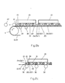
- FIG. 1 An endless conveyor 1 is shown in FIG. 1, which consists of two conveyor belts 2, 3 according to the invention arranged parallel to one another.
- the conveyor belt is driven by a drive station 4 and deflected via deflections 5, 6 and 7.
- an input station 8 which can be a roller conveyor or a conveyor vehicle such as a lift truck or a monorail overhead conveyor, the pallets or large-area containers to be transported and stowed are loaded onto the leading run 9 of the endless Passed to conveyor l.
- a separating device 10 is provided, in which, according to information, the pent-up transport parts are removed from an output conveyor 11.
- the output conveyor 11 can also be a conveyor, as already mentioned for the input station 8.
- the endless conveyor is guided, for example, vertically and over one floor, and the returning run l2 of the endless conveyor l is used as a continuous conveyor for goods arriving there via inputs l3 and goods to be delivered via outputs l4 on the floor below.
- the configuration of the conveyor belt 2 and 3 according to the invention can be seen in the other figures.
- a conveyor unit l5 is transported on the returning runs 12 of the conveyor belts 2, 3.
- the conveyor belts 2 (3) are provided with rubber-elastic axle holders l6, which are fastened on their upper side l8. Fastening the rubber elastic Axle holder l6 on the surface l8 of the conveyor belt 2 (3) can be done by gluing or vulcanizing.
- the rubber-elastic axle holder l6 are laterally connected with bolts l9 to roller holders 2l, which in turn carry a pair of support rollers 22, 22 ⁇ with a storage roller 23 arranged between the support rollers 22 (22 ⁇ ).
- the roll holder 2l is connected to the axle holder l6 by means of side walls 24 (24 ⁇ ) via the bolts l9, so that the roll holder 2l are rotatably connected to the axle holder l6.
- the support rollers are preferably arranged on the left and right of the side walls 24 and 24 ⁇ , while the accumulation roller 23 is arranged between the side walls 24 and 24 ⁇ .
- the support rollers 22, 22 ⁇ and the accumulation roller 23 are arranged on a shaft 25.
- the roller holder 2l with its side walls and its support rollers and the accumulation roller each follows the axle holders l6. According to this arrangement, according to the invention, an elastic guidance of the carrying and accumulating rollers from the traction element is ensured and an elastic centering to the traction element is also possible.
- the conveyor belt 2 (3) is removed in a rollable manner via a support over the accumulation rollers 23 or the support rollers 22, 22 ⁇ and carries 26 conveyor units 15 as a continuous conveyor on its underside.
- it can be the corridor over which the conveyor belt 2, 3 runs, in the case of removal via the support rollers 22 ⁇ , 23 ⁇ , U-rails can be embedded in the corridor, via which the conveyor belts 2, 3 are returned to the leading strand 9.
- the conveyor units l5 are initially carried by the accumulation rollers 23, while the support rollers 22, 22 ⁇ are on rails Support 28, 28 ⁇ , which are arranged parallel to the conveyor belt 2, 3 but at a certain height above it. Due to the rotational mobility of the roller holder 2l with its side walls 24, 24 ⁇ around the bolts l9, the conveyor units l5 are transported at a height above the conveyor belt 2, 3 which essentially corresponds to the height of the rollers in the further conveyor 27. In the area of the transfer between the conveyor belt and the further conveyor 27, the running rails 28, 28 ⁇ are tapered 29 or inclined.
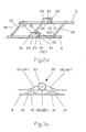
- FIG. 2c A still further embodiment of the subject matter of the invention is shown in FIG. 2c.
- the conveyor belt 2, 3 runs over support rollers 30 in the direction of the arrow and carries the support rollers 22, 22 ⁇ and the accumulation rollers 23, which are guided via axle holders in roller holders 2l, and the accumulation rollers 23 50 shown connected.
- 2d shows a connection according to the invention of two conveyor belts 2, 3 by means of rods 32, which simultaneously connect the axle holder 16 with the side walls 24, 24 24 of the two roll holders 2l as a replacement for the bolts.
- the support rollers 22, 22 ⁇ are arranged outside the side walls 24, 24 ⁇
- the accumulation rollers 23 are arranged inside the side walls 24, 24 ⁇ and the support rollers and accumulation rollers are connected via a shaft 25. Due to the large number of rods 32, which connect each pair of axle holders l6 and each pair of roller holders including side walls, a practically rigid coupling between conveyor belt 2 and conveyor belt 3 is produced, so that no complex straight and synchronous guides for the two conveyor belts have to be used .
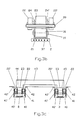
- the roller holder 35 shown in FIG. 3a on a conveyor belt 2 is between two by means of two bolts l9 Axle holders l6 connected via its side walls 24, 24, on the one hand and via side wall extensions 36, 36 ⁇ on the other hand to the other axle holders l6.
- the side walls 24, 24 ⁇ and the side wall extensions 36, 36 ⁇ are made in one piece from elastic material, so that when the conveyor belt 2 is deflected by drive units 4 or deflection units 5, the lengthening of the conveyor belt pieces that occurs between the two axle holders due to the elastic deformation of the side walls and the side wall extensions can be recorded without the accumulation roller 23 or the support rollers 22, 22 'on the surface of the conveyor belt 2 grind.
- the rollers run free by an obtuse-angled arrangement of the side wall and the side wall extension to one another.
- FIG. 3b shows a conveyor belt 2 which is reinforced with steel cables 37 and on which the axle holder 16 is enclosed by the side walls 24, 24 'of the roller holder 2l.
- Guide blocks 39 are also provided on the roller holder 2l and, in the case of the exemplary embodiment according to FIG. 3b, simultaneously take over the guidance of a narrow conveyor belt 2 in the region of a rail guide for the idler rollers.
- the conveyor belts 2, 3 shown in Fig. 3c show a phase of transport in which the support rollers 22, 22 ⁇ run on rails 40, 40 ⁇ and thus take up the load of the conveyor unit, which is carried by the accumulation roller 23, so that the conveyor belts 2, 3 only have to apply the elastic train.
- individual guide blocks 4l, 4l ⁇ are provided, which are centered on side parts 42, 42 ⁇ of the rails 40, 40 ⁇ .
- the conveyor belts 2, 3 with their structures are surmounted by side parts 42, 42 ⁇ . With this, the conveyor belts 2, 3 run even in a channel that is lower than the normal floor area. On the one hand, protection of the conveyor belts 2, 3 is achieved and, on the other hand, U-shaped pallets 43, which stand with their short legs 44, 45 on the storage rollers, can be transported close to the hallway without the risk of a collision Cause injuries to objects or people, since the conveyed goods stop immediately due to the accumulation rollers.
- This embodiment of the subject matter of the invention also achieves the object on which the invention is based.
Abstract
Bei einem Verfahren zum Transport und zum Aufstauen von Paletten mit an einem Zugorgang (2) auf einer Achse angeordneten Führungs- und Staurollen (23) wird zum Zwecke bei derartigen Förderbahnen die zum Transport von Paletten und großflächigen Gegenständen eingesetzt sind, die Wartung und den Verschleiß wesentlich zu verringern, den Lärmpegel durch die Förderanlage zu verringern und gleichzeitig Anfahr- und Bremsstöße auf das zur fördernde Gut zu vermeiden bei einer sicheren Parallelführung eines derartigen Fördererpaares durch eine elastische Führung der Trag- und Staurollen zum Zugorgang und deren elastische Zentrierung zum Zugorgan ein Geradeauslauf erreicht; ebenso wird bei einer Vorrichtung zum Transport und zum Aufstauen von Paletten durch Nachlaufen der Staurollen und Tragrollen hinter dem Achshalter eine eindeutige Zentrierung der Tragrollen und der Staurollen zum Förderer erreicht.In the case of a method for transporting and stowing pallets with guide and accumulation rollers (23) arranged on an axis on a train (2), maintenance and wear are used for the purpose of such conveyor tracks which are used for the transport of pallets and large objects to reduce significantly, to reduce the noise level by the conveyor system and at the same time to avoid start-up and braking impacts on the goods to be conveyed with a safe parallel guidance of such a pair of conveyors by an elastic guidance of the carrying and accumulating rollers to the train and their elastic centering to the train organ, a straight run reached; in the same way, in a device for transporting and stowing pallets, after the accumulation rollers and idler rollers run behind the axle holder, the idler rollers and idler rollers are clearly centered on the conveyor.
Description
Die Erfindung betrifft ein Verfahren zum Transport und zum Aufstauen von Paletten mit an einem Zugorgan auf einer Achse angeordneten Führungs- und Staurollen.The invention relates to a method for transporting and stowing pallets with guide and accumulation rollers arranged on a pulling element on an axis.
Durch die Offenbarung des deutschen Gebrauchsmusters 77 28 979 sind Staurollenketten bekannt geworden, die in der Regel in zwei Strängen parallel nebeneinander angeordnet sind, wobei auf den Buchsen der Rollenketten jeweils Tragrollen frei drehbar angeordnet sind. Die Bolzen der Rollenkette ragen beidseitig seitlich aus der Kette heraus und tragen Laufbuchsen, die auf entsprechend zueinander angeordneten Schienenflächen abrollen. Die Tragrollen ihrerseits liegen auf keiner Führungs- oder Tragfläche auf sondern sind frei drehbar aufgehängt. Die Ketten sind im allgemeinen endlos ausgebildet und werden über geeignete Antriebsmittel in Umlauf gesetzt. Derartige Staurollenketten unterliegen einem beachtlichen Verschleiß und es ist mit diesen kein gleichmäßiger und ruhiger Lauf erzielbar, insbesondere beim Anfahren oder Abbremsen derartiger Ketten treten Stöße auf, die bei einer verschlissenen Kette noch verstärkt zur Geltung kommen. Weiterhin wird bei derartigen Staurollenketten oder Tragkettenförderern beim Umlauf der Förderkette um das Antriebs- oder das Umlenkrad ein Polygoneffekt auftreten, der zum Verschleiß des Antriebs- oder Umlenkrades führt. Des weiteren haben derartige Rollenketten sowohl das Gewicht des transportierten Gegenstandes aufzunehmen, als auch die Zugkraft zu übernehmen. Hierdurch wird der Verschleiß derartiger Rollenketten erhöht.Due to the disclosure of the German utility model 77 28 979 accumulation roller chains are known, which are usually arranged in parallel in two strands next to each other, with each support rollers are freely rotatable on the bushings of the roller chains. The pins of the roller chain protrude laterally from both sides of the chain and carry bushings that roll on correspondingly arranged rail surfaces. The idlers on their part do not rest on any guide or wing but are freely rotatable. The chains are generally endless and are circulated by suitable drive means. Accumulation roller chains of this type are subject to considerable wear and tear, and smooth and smooth running cannot be achieved with them, in particular when starting or braking such chains, shocks occur which are even more pronounced when the chain is worn. Furthermore, with such accumulation roller chains or carrier chain conveyors, a polygon effect will occur when the conveyor chain rotates around the drive wheel or the deflection wheel, which leads to wear of the drive or deflection wheel. Furthermore, roller chains of this type both have to absorb the weight of the transported object and also to take over the tensile force. This increases the wear of such roller chains.
Es wurde zwar versucht (vgl. GM 77 28 979) durch die Anordnung eines mit Fluid füllbaren und entleerbaren Schlauches im Horizontalbereich einer derartigen Rollenkette die Kette durch das transportierte Gewicht nicht zu beanspruchen, da dieses Gewicht über die Tragrollen auf die Laufflächen und den Schlauch übertragen werden; sondern diese lediglich zur Übertragung der Zugkräfte einzusetzen. Hierbei bleiben weiterhin die Verschleißerscheinungen im Umlenkbereich zwischen vorlaufendem und rücklaufendem Trum einer derartigen Rollenkette bestehen und es muß darüber hinaus eine Vorrichtung, die mit Fluid gefüllt und von Fluid entleert werden kann vorgesehen werden; darüber hinaus ist bei einer derartigen Rollenkette, die als Tragkettenförderer oder als Staurollenförderer benutzbar ist, und bei der im allgemeinen ein Paar derartiger Rollenförderer nebeneinander eine Rollbahn bilden, ein häufiges Schmieren der Kettenteile unumgänglich. Werden derartige Rollenketten durch Parallelanordnung zu Förderstrecken und Staurollenbahnen zusammengestellt, so ist ein beachtlicher Aufwand im Hinblick auf den Gleichlauf zwischen den beiden parallel laufenden Ketten unvermeidlich. Auch ist zufolge des auftretenden Verschleisses ein Ausrichten der Trag- zu den Zugelementen nur unter zusätzlichem Verschleiß möglich.Attempts have been made (cf. GM 77 28 979) by arranging a hose that can be filled and emptied with fluid in the horizontal region of such a roller chain, so that the chain is not stressed by the transported weight, since this weight is transferred to the running surfaces and the hose via the idlers will; but only use it to transmit the tensile forces Here, the signs of wear continue to exist in the deflection area between the leading and returning run of such a roller chain, and a device that can be filled with fluid and emptied of fluid must also be provided; In addition, frequent lubrication of the chain parts is unavoidable in such a roller chain, which can be used as a carrying chain conveyor or as an accumulating roller conveyor, and in which a pair of such roller conveyors generally form a roller conveyor next to one another. If roller chains of this type are put together by arranging them parallel to conveyor tracks and accumulating roller conveyors, considerable effort is inevitable with regard to the synchronism between the two chains running in parallel. Also, due to the wear that occurs, alignment of the support elements with the tension elements is only possible with additional wear.
Ausgehend hiervon liegt der Erfindung die Aufgabe zugrunde, bei derartigen Förderbahnen die zum Transport von Paletten und großflächigen Gegenständen eingesetzt sind, die Wartung und den Verschleiß wesentlich zu verringern, den Lärmpegel durch die Förderanlage zu verringern und gleichzeitig Anfahr- und Bremsstöße auf das zu fördernde Gut zu vermeiden bei einer sicheren Parallelführung eines derartigen Fördererpaares. Diese Aufgabe wird durch die kennzeichnenden Merkmale des Anspruchs l gelöst. Durch die elastische Führung der Trag- und Staurollen vom Zugorgan und deren elastische Zentrierung zum Zugorgan wird ein Geradeauslauf erreicht, so daß auch kein Verschleiß durch einen Schräglauf der Tragrolle oder der Staurolle zum Zugorgan auftreten kann.Proceeding from this, the invention is based on the object, in such conveyors which are used for the transport of pallets and large objects, to reduce maintenance and wear substantially, to reduce the noise level by the conveyor system and at the same time start-up and braking impacts on the material to be conveyed to avoid with a safe parallel guidance of such a pair of conveyors. This object is achieved by the characterizing features of
Bei einer Vorrichtung zum Transport und zum Aufstauen von Paletten mit an einem Zugorgan auf einer Achse angeordneten Tragrollen, dazwischen angeordneter Staurolle, wird die der Erfindung zugrundeliegende Aufgabe mit den kennzeichnenden Merkmalen des Anspruchs 2 gelöst. Durch die auf einen Fördergurt aufgebrachten Achshalter, die insbesondere mittels Verklebung auf der Fördergurtoberseite angeordnet sind und die Anordnung eines Rollenhalters, der Staurolle und Tragrollen trägt und der dem Achshalter nachläuft, wobei Seitenwandungen des Rollenhalters als Haltestreben für den Rollenhalter selbst mittels Bolzen mit dem Achshalter drehbeweglich verbunden sind, wird eine eindeutige Zentrierung der Tragrollen und der Staurollen zum Fördergurt zufolge Nachlaufs des Rollenhalters zum Achshalter erreicht. Insbesondere können beim Einfahren in Staurollenbahnen, bei denen oberhalb des Fördergurts Schienen für die Tragrollen angeordnet sind, Einfahrstöße zufolge Verkanten des Rollenhalters zum Fördergurt, wie es bei Rollenkettenförderern, insbesondere im ausgeschlagenen Zustand der Fall ist, nicht auftreten. Bei dem Fördergurt selbst handelt es sich um einen mit Stahlseilen verstärkten endlosen Gummigurt oder um einen mit Glasfaserseilen verstärkten Gummi- oder Kunststoffgurt; auch können Textil- oder Polyamidgewebe als Verstärkungen eingesetzt werden.In the case of a device for transporting and stowing pallets with support rollers arranged on a pulling element on an axis, with a storage roller arranged in between, the object on which the invention is based is achieved with the characterizing features of
Gemäß kennzeichnenden Merkmalen des Anspruchs 3 wird eine Fördereinrichtung unter Schutz gestellt, mit der die der Erfindung zugrundeliegende Aufgabe auch beim Reversierbetrieb des Förderorgans, also bei Umkehrung der Förderrichtung gelöst wird. Durch die Anordnung elastischer Seitenwandungen, die aus mit Kunststoff ummantelten federnden Stahlwangen bestehen kann, oder die aus elastischen mit Verstärkungen versehenen Kunststoffen bestehen kann, die jeweils mit den Achshaltern drehbeweglich verbunden sind, werden durch die konstruktive Ausbildung der Seitenwandungen, die sich in einem stumpfen Winkel im Bereich der Achse, der Tragrollen und der Staurolle treffen und die bevorzugt einstückig sind, die durch den Umlauf um Antriebs- oder Umlenkräder zufolge Längung des Fördergurts auftretenden Spannungen ohne Verschleiß metallischer Bauteile aneinander aufgenommen.According to the characterizing features of
Mit den kennzeichnenden Merkmalen des Anspruchs 4 wird durch Anordnung von, die beiden Fördergurte verbindenden Stäbe ohne zusätzlichen mechanischen Aufwand eine Parallelführung der zu einer Stau- und/oder Förderstrecke paarweise angeordneten Fördergurte unter Schutz gestellt.With the characterizing features of
Wie in Anspruch 5 in den kennzeichnenden Merkmalen unter Schutz gestellt, dienen im rücklaufenden Trum der Stau- und/oder Förderstrecke erfindungsgemäß die Tragrollen oder die Staurollen selbst als rollende Abstützung. Hierdurch wird eine beachtliche Verringerung der Reibung im rücklaufenden Trum des erfindungsgemäßen Fördergurts erreicht.As in
Die in Anspruch 6 unter Schutz gestellte Ausgestaltung des Erfindungsgegenstandes schlägt vor, am Rollenhalter Führungsklötze anzuordnen. Dies ist dann von besonderem Vorteil, wenn Staurollen und Tragrollen großer Breite erfindungsgemäß mit einem schmalen Fördergurt verbunden sind und wenn die Tragrollen auf dem gesamten Umlauf auf Führungsschienen geführt sind, an deren Innenseite sich die Führungsklötze erfindungsgemäß zentrieren können.The protection of the subject matter of the invention proposed in
Mit den kennzeichnenden Merkmalen des Anspruchs 7 wird eine Vorrichtung unter Schutz gestellt, bei der beim Förderbetrieb die Staurolle arretiert und somit als Tragrolle dient. Im Bereich einer Staustrecke des endlosen Fördergurts in dessen Bereich die Tragrollen auf Schienen geführt sind, deren Abstand zum Fördergurt größer als der Radius der Staurolle ist, rollt die Staurolle am gestauten Bauteil beispielsweise der Unterseite einer gestauten Palette oder eines großflächigen Bauteils ab.With the characterizing features of
Die kennzeichnenden Merkmale des Anspruchs 8 zeigen eine noch weitere Ausgestaltung des erfindungsgemäßen Fördergurts mit Trag- und Staurollen, die insbesondere beim stoßfreien Übergang von Fördergut von einem Staurollenförderer auf einen Rollenförderer oder umgekehrt angewandt werden. Hierbei befindet sich der weiterführende Rollenförderer zwischen den parallelen Strängen der Stau- und/oder Fördereinrichtung, so daß bei gleichsinnigem Antrieb des Stauförderers und des nachgeordneten Förderers zufolge Wegtauchens der Staurolle ein stoßfreier Übergang der Palette oder des großflächigen Fördergutes auf den Rollenförderer durchgeführt wird. Anstelle eines gleichsinnigen Antriebs kann auch der weiterführende Förderer insgesamt eine Neigung besitzen, so daß das zu übergebende Fördergut durch eigene Schwerkraft weitertransportiert wird. Diese Anordnung kann auch im Reversierbetrieb eingesetzt werden, wenn von dem nachgeschalteten Förderer auf den Fördergurt, der als Stau- und/oder Förderstrekke ausgebildet ist, übergeben werden soll; hierbei sind die Trag- und Staurollen, insbesondere gemäß Anspruch 3 auf dem Fördergurt angeordnet.The characterizing features of
Bei einer Ausgestaltung des endlosen Fördergurts gemäß Anspruch 5, bei der im rücklaufenden Trum die Trag- oder Staurollen den Fördergurt abstützen, kann erfindungsgemäß die nunmehr flache Oberseite zum Transport von Fördergütern herangezogen werden. Dies ist insbesondere dann von Vorteil, wenn der Höhenunterschied zwischen vorlaufendem und rücklaufendem Trum so groß ist, daß Zwischenböden eingezogen werden können, auf denen Bedienungspersonal oder Roboter, die auf dem vorlaufenden Trum des Stauförderers transportierten, auf Paletten gelagerten Bauteile bearbeiten. In diesem Fall kann das in einer anderen Ebene rücklaufende Trum als Fördergurt mit glatter Oberfläche benutzt werden.In an embodiment of the endless conveyor belt according to
In der nachfolgenden Beschreibung wird die Erfindung anhand einer Zeichnung näher erläutert. Es zeigen in schematischer Darstellung:
- Fig. l einen als Stauförderer im vorlaufenden Trum und als Stetigförderer im rücklaufenden Trum ausgebildeten erfindungsgemäßen Fördergurt
- Fig. 2a den Transport eines Fördergutes auf dem rücklaufenden Gurtband
- Fig. 2b den Übergang von einem als Stauförderer ausgebildeten erfindungsgemäßen Fördergurt auf einen Rollenförderer
- Fig. 2c den Transport von Fördergut auf einer vom erfindungsgemäßen Fördergurt arretierten Staurolle
- Fig. 2d die Verbindung zweier erfindungsgemäßer Fördergurt zu einer Förderstrecke
- Fig. 3a einen für Reversierbetrieb erfindungsgemäß ausgebildeten Rollenhalter
- Fig. 3b in vergrößertem Maßstab einen erfindungsgemäßen Fördergurt mit Trag- und Staurolle und
- Fig. 3c einen erfindungsgemäßen Fördergurt im Bereich einer Staustrecke.
- Fig. L formed as a accumulation conveyor in the leading strand and as a continuous conveyor in the return strand conveyor belt according to the invention
- 2a shows the transport of a conveyed good on the returning belt
- 2b shows the transition from a conveyor belt according to the invention designed as a accumulation conveyor to a roller conveyor
- 2c shows the transport of material to be conveyed on a storage roller locked by the conveyor belt according to the invention
- Fig. 2d the connection of two conveyor belts according to the invention to a conveyor line
- 3a shows a roll holder designed according to the invention for reversing operation
- Fig. 3b on an enlarged scale a conveyor belt according to the invention with carrying and storage roller and
- 3c a conveyor belt according to the invention in the region of a storage section.
Gleiche Bauteile werden in den verschiedenen Figuren mit denselben Bezugszeichen bezeichnet.Identical components are identified with the same reference symbols in the various figures.
In Fig. l ist ein endloser Förderer l dargestellt, der aus zwei parallel zueinander angeordneten erfindungsgemäßen Fördergurtenn 2, 3 besteht. Die Fördergurt werden von einer Antriebsstation 4 angetrieben und über Umlenkungen 5, 6 und 7 umgelenkt.An
Von einer Eingabestation 8, bei der es sich um einen Rollenförderer oder auch um ein Förderfahrzeug wie einen Hublader oder auch eine Ein-Schienen-Hängebahn handeln kann, werden die mitzutransportierenden und zu stauenden Bauteile beladenen Paletten oder großflächigen Behälter an das vorlaufende Trum 9 des endlosen Förderers l übergeben. Am Ende des vorlaufenden Trums 9 ist eine Vereinzelungsvorrichtung l0 vorgesehen, bei der entsprechend Information von einem Ausgabeförderer ll die aufgestauten Transportteile abgenommen werden. Bei dem Ausgabeförderer ll kann es sich ebenfalls um Förderer, wie bereits zur Eingabestation 8 genannt, handeln.From an
Zwischen der Antriebsstation 4 und der Umlenkung 5 wird der endlose Förderer beispielsweise vertikal und über ein Stockwerk geführt und im darunter liegenden Stockwerk wird das rücklaufende Trum l2 des endlosen Förderers l als Stetigförderer für dort über Eingaben l3 ankommendes Gut und über Ausgaben l4 abzugebendes Gut genutzt. Die erfindungsgemäße Ausgestaltung des Fördergurt 2 und 3 ist den weiteren Figuren zu entnehmen.Between the
So wird gemäß Fig. 2a auf den rücklaufenden Trumen l2 der Fördergurte 2, 3 eine Fördereinheit l5 transportiert.2a, a conveyor unit l5 is transported on the returning runs 12 of the
Hierzu sind die Fördergurte 2 (3) mit gummielastischen Achshaltern l6 versehen, die auf ihrer Oberseite l8 befestigt sind. Die Befestigung der gummielastischen Achshalter l6 auf der Oberfläche l8 des Fördergurts 2 (3) kann mittels Kleben oder Vulkanisieren erfolgen. Die gummielastischen Achshalter l6 sind mit Bolzen l9 seitlich mit Rollenhaltern 2l verbunden, die ihrerseits ein Tragrollenpaar 22, 22ʹ mit einer zwischen den Tragrollen 22 (22ʹ) angeordneten Staurolle 23 tragen. Der Rollenhalter 2l ist mittels Seitenwandungen 24 (24ʹ) über die Bolzen l9 mit dem Achshalter l6 verbunden, so daß die Rollenhalter 2l drehbeweglich mit dem Achshalter l6 verbunden sind. Von den Rollenhaltern 2l sind der Übersicht halber die vorderen Seitenwandungen 24ʹ nicht dargestellt, so daß lediglich die rückwärtigen Seitenwandungen 24 sichtbar sind. Bevorzugt sind die Tragrollen links und rechts der Seitenwandungen 24 bzw. 24ʹ angeordnet, während die Staurolle 23 zwischen den Seitenwandungen 24 bzw. 24ʹ angeordnet ist. Die Tragrollen 22, 22ʹ und die Staurolle 23 sind auf einer Welle 25 angeordnet.For this purpose, the conveyor belts 2 (3) are provided with rubber-elastic axle holders l6, which are fastened on their upper side l8. Fastening the rubber elastic Axle holder l6 on the surface l8 of the conveyor belt 2 (3) can be done by gluing or vulcanizing. The rubber-elastic axle holder l6 are laterally connected with bolts l9 to roller holders 2l, which in turn carry a pair of
Wie der Fig. 2a weiter zu entnehmen, läuft der Rollenhalter 2l mit seinen Seitenwandungen und seinen Tragrollen und der Staurolle jeweils den Achshaltern l6 nach. Zufolge dieser Anordnung ist erfindungsgemäß ein elastisches Führen der Trag- und Staurollen vom Zugorgan gewährleistet und auch ein elastisches Zentrieren zum Zugorgan möglich.As can further be seen from FIG. 2a, the roller holder 2l with its side walls and its support rollers and the accumulation roller each follows the axle holders l6. According to this arrangement, according to the invention, an elastic guidance of the carrying and accumulating rollers from the traction element is ensured and an elastic centering to the traction element is also possible.
Wie weiterhin der Fig. 2a entnehmbar, wird der Fördergurt 2 (3) rollbar über eine Unterlage über die Staurollen 23 oder die Tragrollen 22, 22ʹ abgetragen und trägt als Stetigförderer auf seiner Unterseite 26 Fördereinheiten l5. Im Fall des rollenden Abtragens über die Staurollen 23 kann es sich um den Flur, über den der Fördergurt 2, 3 läuft, handeln, im Falle des Abtragens über die Tragrollen 22ʹ, 23ʹ können U-Schienen im Flur eingelassen sein, über die die Fördergurte 2, 3 zum vorlaufenden Trum 9 zurückgeführt werden.As can also be seen in FIG. 2a, the conveyor belt 2 (3) is removed in a rollable manner via a support over the
Bei der in Fig. 2b dargestellten Übergabestation zwischen einem Fördergurt 2 (3) und einem weiterführenden Förderer 27, der im Ausführungsbeispiel schematisch als Rollenförderer dargestellt ist, werden die Fördereinheiten l5 zunächst von den Staurollen 23 getragen, währenddem sich die Tragrollen 22, 22ʹ auf Laufschienen 28, 28ʹ abstützen, die parallel zum Fördergurt 2, 3 jedoch in einer gewissen Höhe über diesem angeordnet sind. Zufolge der Drehbeweglichkeit der Rollenhalter 2l mit ihren Seitenwandungen 24, 24ʹ um die Bolzen l9 werden die Fördereinheiten l5 in einer Höhe über dem Fördergurt 2, 3 transportiert, die im wesentlichen der Höhe der Rollen im weiterführenden Förderer 27 entspricht. Im Bereich der Übergabe zwischen Fördergurt und weiterführendem Förderer 27 sind die Laufschienen 28, 28ʹ verjüngt 29 oder geneigt ausgebildet. Damit ist zum einen die Gewähr des stoßfreien Übergangs der Fördereinheiten auf einen weiterführenden Förderer 27 gegeben und zum anderen die elastische Führung der Trag- und Staurollen sowie deren Zentrierung durch das Zugorgan gewährleistet. Der Fördergurt 2, 3 selbst wird über Stützrollen 30; in seinem vorlaufenden Trum abgetragen und über die Antriebsstation 4 als rücklaufendes Trum zurückgeführt. Der Übersichtlichkeit halber wurden im Bereich der Antriebsstation und des rücklaufenden Trums keine Achshalter l6 und Rollenhalter 2l dargestellt.In the transfer station shown in Fig. 2b between a conveyor belt 2 (3) and a
Eine noch weitere Ausgestaltung des Erfindungsgegenstandes wird in Fig. 2c dargestellt. Der Fördergurt 2, 3 läuft über Stützrollen 30 in Richtung des Pfeils und trägt die über Achshalter in Rollenhaltern 2l geführten Tragrollen 22, 22ʹ und die Staurollen 23. Über die Seitenwandungen 24, 24ʹ sind die Rollenhalter 2l drehbeweglich mit den Bolzen l9, wie durch Doppelpfeile 50 dargestellt, verbunden. Wird nunmehr eine Fördereinheit l5 über eine Eingabestation 8 (vgl. Fig. l) dem Fördergurt 2, 3 zugeführt, so stützt sich diese auf den Staurollen 23 ab. Zufolge Ausgestaltung der Staurolle 23 in ihrem Durchmesser, der gering größer als die Höhe 3l der Seitenwandungen 24, 24ʹ ist, wird die Staurolle 23 selbst auf die Oberseite des Fördergurts 2, 3 geringfügig aufgepreßt, so daß eine Rotation dieser nicht stattfinden kann. Ist in der Förderstrecke eine Staustrecke vorgesehen, so werden nicht dargestellte Schienen oberhalb des Fördergurts 2, 3 angeordnet, auf die die Tragrollen 22, 22ʹ auflaufen. Durch die Drehbeweglichkeit um den Bolzen l9 wird der Rollenhalter angehoben, die Staurolle kommt frei von der Oberseite des Fördergurts 2, 3 und unter Festhalten der Fördereinheit l5 wird der Fördergurt 2, 3 durch Abrollen der Staurollen 23 an der Unterseite der Fördereinheit l5 weiter transportiert.A still further embodiment of the subject matter of the invention is shown in FIG. 2c. The
In Fig. 2d wird eine erfindungsgemäße, Verbindung zweier Fördergurte 2, 3 mittels Stäben 32, die gleichzeitig als Ersatz für die Bolzen die Achshalter l6 mit den Seitenwandungen 24, 24ʹ der beiden Rollenhalter 2l verbinden, dargestellt. Hierbei sind die Tragrollen 22, 22ʹ außerhalb der Seitenwandungen 24, 24ʹ angeordnet, während die Staurollen 23 innerhalb der Seitenwandungen 24, 24ʹ angeordnet sind und die Tragrollen und Staurollen über eine Welle 25 verbunden sind. Durch die Vielzahl der Stäbe 32, die jedes Paar von Achshaltern l6 und jedes Paar von Rollenhaltern einschließlich Seitenwandungen verbinden, wird eine praktisch starre Kupplung zwischen Fördergurt 2 und Fördergurt 3 hergestellt, so daß keine aufwendigen Gerad- und Gleichlaufführungen für die beiden Fördergurte eingesetzt werden müssen.2d shows a connection according to the invention of two
Der in Fig. 3a auf einem Fördergurt 2 dargestellte Rollenhalter 35 ist mittels zweier Bolzen l9 zwischen zwei Achshaltern l6 über seine Seitenwandungen 24, 24ʹ einerseits und über Seitenwandungsverlängerungen 36, 36ʹ andererseits mit den anderen Achshaltern l6 verbunden. Die Seitenwandungen 24, 24ʹ und die Seitenwandungsverlängerungen 36, 36ʹ sind einstückig aus elastischem Material hergestellt, so daß bei Umlenkungen des Fördergurts 2 um Antriebseinheiten 4 oder Umlenkeinheiten 5, die auftretende Längung des Fördergurtstücke zwischen den beiden Achshaltern zufolge der elastischen Verformung der Seitenwandungen und der Seitenwandungsverlängerungen aufgenommen werden kann, ohne daß die Staurolle 23 oder die Tragrollen 22, 22ʹ an der Oberfläche des Fördergurts 2 schleifen. Das Freilaufen der Rollen geschieht durch eine stumpfwinklige Anordnung der Seitenwandung und der Seitenwandungsverlängerung zueinander.The
Die in Fig. 3b vergrößerte Darstellung zeigt einen Fördergurt 2, der mit Stahlseilen 37 verstärkt ist und auf dem der Achshalter l6 von den Seitenwandungen 24, 24ʹ des Rollenhalters 2l eingeschlossen wird. Am Rollenhalter 2l sind auch Führungsklötze 39 vorgesehen, die im Falle des Ausführungsbeispiels nach Fig. 3b gleichzeitig die Führung eines schmalen Fördergurts 2 im Bereich einer Schienenführung für die Tragrollen übernehmen.The enlarged illustration in FIG. 3b shows a
Die in Fig. 3c dargestellten Fördergurte 2, 3 zeigen eine Phase des Transports, bei dem die Tragrollen 22, 22ʹ auf Schienen 40, 40ʹ laufen und somit die Last der Fördereinheit, die von der Staurolle 23 getragen wird, aufnehmen, so daß die Fördergurte 2, 3 lediglich den elastischen Zug aufbringen müssen. In diesem Fall sind einzelne Führungsklötze 4l, 4lʹ vorgesehen, die sich an Seitenteilen 42, 42ʹ der Schienen 40, 40ʹ zentrieren.The
Wie in dieser Figur weiter dargestellt, werden die Fördergurte 2, 3 mit ihren Aufbauten von Seitenteilen 42, 42ʹ überragt. Hiermit laufen die Fördergurte 2, 3 selbst in einem Kanal, der tiefer liegt als die normale Flurfläche ist. Zum einen wird hierdurch ein Schutz der Fördergurte 2, 3 erreicht und zum anderen können U-förmige Paletten 43, die mit ihren kurzen Schenkeln 44, 45 auf den Staurollen aufstehen nahe über Flur transportiert werden, ohne daß die Gefahr besteht, bei einem Zusammenstoß mit Gegenständen oder Personen Verletzungen hervorzurufen, da zufolge der Staurollen das geförderte Gut sofort stehenbleibt. Diese erfindungsgemäße Ausgestaltung des Erfindungsgegenstandes löst ebenfalls die der Erfindung zugrundeliegende Aufgabe.As further shown in this figure, the
Claims (8)
Priority Applications (4)
| Application Number | Priority Date | Filing Date | Title |
|---|---|---|---|
| DE8787101561T DE3764634D1 (en) | 1987-02-05 | 1987-02-05 | DEVICE FOR TRANSPORTING AND STOCKING PALLETS. |
| EP87101561A EP0277258B1 (en) | 1987-02-05 | 1987-02-05 | Device for transporting and accumulating pallets |
| ES87101561T ES2017648B3 (en) | 1987-02-05 | 1987-02-05 | PROCEDURE FOR THE TRANSPORT AND COUPLING OF PALLETS, AS WELL AS THE ROLL OF ROLLERS FOR TRANSPORT AND COUPLING. |
| US07/114,208 US4852718A (en) | 1987-02-05 | 1987-10-28 | Conveyor system |
Applications Claiming Priority (1)
| Application Number | Priority Date | Filing Date | Title |
|---|---|---|---|
| EP87101561A EP0277258B1 (en) | 1987-02-05 | 1987-02-05 | Device for transporting and accumulating pallets |
Publications (2)
| Publication Number | Publication Date |
|---|---|
| EP0277258A1 true EP0277258A1 (en) | 1988-08-10 |
| EP0277258B1 EP0277258B1 (en) | 1990-08-29 |
Family
ID=8196721
Family Applications (1)
| Application Number | Title | Priority Date | Filing Date |
|---|---|---|---|
| EP87101561A Expired - Lifetime EP0277258B1 (en) | 1987-02-05 | 1987-02-05 | Device for transporting and accumulating pallets |
Country Status (4)
| Country | Link |
|---|---|
| US (1) | US4852718A (en) |
| EP (1) | EP0277258B1 (en) |
| DE (1) | DE3764634D1 (en) |
| ES (1) | ES2017648B3 (en) |
Cited By (9)
| Publication number | Priority date | Publication date | Assignee | Title |
|---|---|---|---|---|
| EP0391247A2 (en) * | 1989-04-06 | 1990-10-10 | Dürr GmbH | Conveyor belt having accumulating rollers |
| DE9106634U1 (en) * | 1991-05-31 | 1991-10-17 | Fredenhagen Kg, 6050 Offenbach, De | |
| EP0473953A1 (en) * | 1990-09-05 | 1992-03-11 | Dürr GmbH | Belt conveyor |
| EP0523444A1 (en) * | 1991-07-17 | 1993-01-20 | Continental Aktiengesellschaft | Conveying belt with carrier means |
| EP0558820A1 (en) * | 1992-03-05 | 1993-09-08 | Stotz, Krämer GmbH Materialflussysteme und Automation | Accumulating roller belt conveyor |
| DE4219100A1 (en) * | 1992-06-11 | 1993-12-16 | Thyssen Aufzuege Gmbh | Belt conveyor with buffer roller - has roller holding elements, each with tapered holder part protruding over element foot part |
| BE1008352A3 (en) * | 1991-05-24 | 1996-04-02 | Mannesmann Ag | Conveyor accumulation. |
| DE10355942A1 (en) * | 2003-11-29 | 2005-06-30 | Frank Schmid GmbH Förder- und Systemtechnik | Roller chair for a conveyer belt, e.g. for a conveyer belt for moving car body parts in a vehicle assembly line, has a vertically mounted guide roller that is supported between the inner surfaces of guide profiles |
| CN116161373A (en) * | 2022-12-30 | 2023-05-26 | 江苏奔牛港务集团有限公司 | Automatic loading and unloading equipment for bagged goods and control method thereof |
Families Citing this family (10)
| Publication number | Priority date | Publication date | Assignee | Title |
|---|---|---|---|---|
| DE4108613C2 (en) * | 1990-03-22 | 1995-05-24 | Eisenmann Foerdertech | Conveyor belt conveyor |
| US5454687A (en) * | 1990-09-06 | 1995-10-03 | Johnson; Peter E. | High speed sorter/stacker |
| EP0800902B1 (en) * | 1996-04-11 | 2002-03-06 | Dieffenbacher Schenck Panel GmbH | Method for continuous manufacturing of a mat for boards of wooden or like material |
| DE19615792C1 (en) * | 1996-04-20 | 1997-06-05 | Man Takraf Foerdertechnik Gmbh | Carrier flap with base structure for elevator for loose material |
| US6168011B1 (en) | 1998-01-30 | 2001-01-02 | Sws Scharf-Westfalia Industrial Systems Gmbh | Accumulation conveyor system |
| US6102194A (en) * | 1999-02-16 | 2000-08-15 | Belcan Corporation | Pallet type transfer device |
| US6161685A (en) * | 1999-03-26 | 2000-12-19 | Rexnord Corporation | Thermoplastic chain link for a modular conveyor chain |
| IT249695Y1 (en) * | 2000-01-13 | 2003-05-28 | Fata Automation | TRANSPORT PLANT WITH CONVEYOR EQUIPPED WITH ROLLS FOR FREE SUPPORT OF TRANSPORT ELEMENTS |
| DE102004014745B4 (en) * | 2004-03-22 | 2009-01-02 | Telair International Gmbh | cargo deck |
| DE102011010544A1 (en) * | 2011-02-07 | 2012-08-09 | Eisenmann Ag | Tragbahnförderer and conveyor system with such |
Citations (2)
| Publication number | Priority date | Publication date | Assignee | Title |
|---|---|---|---|---|
| US3197020A (en) * | 1962-04-16 | 1965-07-27 | Ajem Lab Inc | Conveyor chain link |
| DE2210341A1 (en) * | 1971-03-06 | 1972-09-14 | Gianetti Spa | Roller chain |
Family Cites Families (7)
| Publication number | Priority date | Publication date | Assignee | Title |
|---|---|---|---|---|
| US1768482A (en) * | 1930-06-24 | Conveyer mechanism | ||
| US722689A (en) * | 1902-01-02 | 1903-03-17 | H R Sanborn | Sheet-glass carrier for leers. |
| US1197145A (en) * | 1914-01-05 | 1916-09-05 | Samuel Olson | Package-conveyer. |
| US2687796A (en) * | 1946-02-25 | 1954-08-31 | Fmc Corp | Conveyer chain for can feeding mechanisms |
| US3174616A (en) * | 1962-10-15 | 1965-03-23 | Rex Chainbelt Inc | Conveyor chain and attachment |
| NL6705459A (en) * | 1967-04-18 | 1968-10-21 | ||
| DE7728979U1 (en) * | 1977-09-19 | 1979-03-15 | Liebherr-Verzahntechnik Gmbh, 8960 Kempten | DEVICE FOR TRANSPORTING HEAVY OBJECTS OR PALLETS |
-
1987
- 1987-02-05 DE DE8787101561T patent/DE3764634D1/en not_active Expired - Lifetime
- 1987-02-05 EP EP87101561A patent/EP0277258B1/en not_active Expired - Lifetime
- 1987-02-05 ES ES87101561T patent/ES2017648B3/en not_active Expired - Lifetime
- 1987-10-28 US US07/114,208 patent/US4852718A/en not_active Expired - Fee Related
Patent Citations (2)
| Publication number | Priority date | Publication date | Assignee | Title |
|---|---|---|---|---|
| US3197020A (en) * | 1962-04-16 | 1965-07-27 | Ajem Lab Inc | Conveyor chain link |
| DE2210341A1 (en) * | 1971-03-06 | 1972-09-14 | Gianetti Spa | Roller chain |
Cited By (13)
| Publication number | Priority date | Publication date | Assignee | Title |
|---|---|---|---|---|
| DE3934233A1 (en) * | 1989-04-06 | 1990-10-11 | Duerr Gmbh & Co | BELT CONVEYOR |
| EP0391247A3 (en) * | 1989-04-06 | 1991-04-03 | Dürr GmbH | Conveyor belt having accumulating rollers |
| EP0391247A2 (en) * | 1989-04-06 | 1990-10-10 | Dürr GmbH | Conveyor belt having accumulating rollers |
| EP0473953A1 (en) * | 1990-09-05 | 1992-03-11 | Dürr GmbH | Belt conveyor |
| DE4028130A1 (en) * | 1990-09-05 | 1992-03-12 | Duerr Gmbh & Co | BELT CONVEYOR |
| BE1008352A3 (en) * | 1991-05-24 | 1996-04-02 | Mannesmann Ag | Conveyor accumulation. |
| DE9106634U1 (en) * | 1991-05-31 | 1991-10-17 | Fredenhagen Kg, 6050 Offenbach, De | |
| EP0523444A1 (en) * | 1991-07-17 | 1993-01-20 | Continental Aktiengesellschaft | Conveying belt with carrier means |
| EP0558820A1 (en) * | 1992-03-05 | 1993-09-08 | Stotz, Krämer GmbH Materialflussysteme und Automation | Accumulating roller belt conveyor |
| DE4219100A1 (en) * | 1992-06-11 | 1993-12-16 | Thyssen Aufzuege Gmbh | Belt conveyor with buffer roller - has roller holding elements, each with tapered holder part protruding over element foot part |
| DE10355942A1 (en) * | 2003-11-29 | 2005-06-30 | Frank Schmid GmbH Förder- und Systemtechnik | Roller chair for a conveyer belt, e.g. for a conveyer belt for moving car body parts in a vehicle assembly line, has a vertically mounted guide roller that is supported between the inner surfaces of guide profiles |
| CN116161373A (en) * | 2022-12-30 | 2023-05-26 | 江苏奔牛港务集团有限公司 | Automatic loading and unloading equipment for bagged goods and control method thereof |
| CN116161373B (en) * | 2022-12-30 | 2023-06-23 | 江苏奔牛港务集团有限公司 | Automatic loading and unloading equipment for bagged goods and control method thereof |
Also Published As
| Publication number | Publication date |
|---|---|
| US4852718A (en) | 1989-08-01 |
| ES2017648B3 (en) | 1991-03-01 |
| EP0277258B1 (en) | 1990-08-29 |
| DE3764634D1 (en) | 1990-10-04 |
Similar Documents
| Publication | Publication Date | Title |
|---|---|---|
| EP0277258B1 (en) | Device for transporting and accumulating pallets | |
| DE3528559A1 (en) | SORTING SYSTEM | |
| EP2714496B1 (en) | Apparatus for conveying and plant for surface-treating articles | |
| EP1477437A2 (en) | Modular construction system for a conveyor for longitudinal or transversal transport of piece-goods carriers | |
| DE2838974C2 (en) | Roller conveyor with U-shaped beams that are open at the top | |
| EP1897824B1 (en) | Piece goods conveyor, in particular for air baggage | |
| EP0096776A2 (en) | Inclined lift for goods conveyance | |
| DE3317403C1 (en) | Jam conveyor with an endless support and guide rail running in the horizontal plane | |
| EP1619146A1 (en) | Device for distributing load carriers for piece goods | |
| DE10340868B4 (en) | Conveyor system, in particular an airport baggage conveyor system, for the transport of general cargo serving containers | |
| EP0541850B1 (en) | Curvilinear plate conveyor | |
| DE3790593C2 (en) | ||
| EP3529180B1 (en) | Conveying system | |
| EP0750577B1 (en) | Mono-or twin-rail overhead chain conveyor | |
| EP2484607B1 (en) | Conveyor and conveying equipment with such conveyor | |
| EP0180177B1 (en) | Transporting device for merchandise, especially for loading the loading area of a vehicle or of a container | |
| EP2610099B1 (en) | Transport device for light conveyed goods, in particular vehicle components | |
| DE10328555A1 (en) | Device for removing load carriers | |
| EP3169571A1 (en) | Drive carriage for a transport device, and transport system | |
| DE3003180C2 (en) | Carrying chain conveyor | |
| EP1057758A1 (en) | Vertical conveyor according to the paternoster-type | |
| DE10340867A1 (en) | Conveyor system, in particular an airport baggage conveyor system, and guide means for such a conveyor system | |
| DE4323127A1 (en) | Curved belt conveyor with support frame free of webbing rolls | |
| EP0088042B1 (en) | Reversible accumulating chain conveyor for elongate goods | |
| DE19517832C1 (en) | Drag travelling gear for overhead conveyor |
Legal Events
| Date | Code | Title | Description |
|---|---|---|---|
| PUAI | Public reference made under article 153(3) epc to a published international application that has entered the european phase |
Free format text: ORIGINAL CODE: 0009012 |
|
| 17P | Request for examination filed |
Effective date: 19871125 |
|
| AK | Designated contracting states |
Kind code of ref document: A1 Designated state(s): AT BE CH DE ES FR GB GR IT LI LU NL SE |
|
| RBV | Designated contracting states (corrected) |
Designated state(s): BE DE ES FR GB IT SE |
|
| 17Q | First examination report despatched |
Effective date: 19881031 |
|
| ITF | It: translation for a ep patent filed |
Owner name: ING. ZINI MARANESI & C. S.R.L. |
|
| GRAA | (expected) grant |
Free format text: ORIGINAL CODE: 0009210 |
|
| AK | Designated contracting states |
Kind code of ref document: B1 Designated state(s): BE DE ES FR GB IT SE |
|
| REF | Corresponds to: |
Ref document number: 3764634 Country of ref document: DE Date of ref document: 19901004 |
|
| GBT | Gb: translation of ep patent filed (gb section 77(6)(a)/1977) | ||
| ET | Fr: translation filed | ||
| PLBE | No opposition filed within time limit |
Free format text: ORIGINAL CODE: 0009261 |
|
| STAA | Information on the status of an ep patent application or granted ep patent |
Free format text: STATUS: NO OPPOSITION FILED WITHIN TIME LIMIT |
|
| 26N | No opposition filed | ||
| ITTA | It: last paid annual fee | ||
| EAL | Se: european patent in force in sweden |
Ref document number: 87101561.6 |
|
| PGFP | Annual fee paid to national office [announced via postgrant information from national office to epo] |
Ref country code: SE Payment date: 19960117 Year of fee payment: 10 |
|
| PGFP | Annual fee paid to national office [announced via postgrant information from national office to epo] |
Ref country code: GB Payment date: 19960119 Year of fee payment: 10 |
|
| PGFP | Annual fee paid to national office [announced via postgrant information from national office to epo] |
Ref country code: FR Payment date: 19960201 Year of fee payment: 10 |
|
| PGFP | Annual fee paid to national office [announced via postgrant information from national office to epo] |
Ref country code: ES Payment date: 19960213 Year of fee payment: 10 |
|
| PG25 | Lapsed in a contracting state [announced via postgrant information from national office to epo] |
Ref country code: GB Effective date: 19970205 |
|
| PG25 | Lapsed in a contracting state [announced via postgrant information from national office to epo] |
Ref country code: SE Effective date: 19970206 Ref country code: ES Free format text: LAPSE BECAUSE OF NON-PAYMENT OF DUE FEES Effective date: 19970206 |
|
| GBPC | Gb: european patent ceased through non-payment of renewal fee |
Effective date: 19970205 |
|
| PG25 | Lapsed in a contracting state [announced via postgrant information from national office to epo] |
Ref country code: FR Effective date: 19971030 |
|
| EUG | Se: european patent has lapsed |
Ref document number: 87101561.6 |
|
| REG | Reference to a national code |
Ref country code: FR Ref legal event code: ST |
|
| REG | Reference to a national code |
Ref country code: ES Ref legal event code: FD2A Effective date: 19990301 |
|
| PG25 | Lapsed in a contracting state [announced via postgrant information from national office to epo] |
Ref country code: IT Free format text: LAPSE BECAUSE OF NON-PAYMENT OF DUE FEES;WARNING: LAPSES OF ITALIAN PATENTS WITH EFFECTIVE DATE BEFORE 2007 MAY HAVE OCCURRED AT ANY TIME BEFORE 2007. THE CORRECT EFFECTIVE DATE MAY BE DIFFERENT FROM THE ONE RECORDED. Effective date: 20050205 |
|
| PGFP | Annual fee paid to national office [announced via postgrant information from national office to epo] |
Ref country code: BE Payment date: 20060203 Year of fee payment: 20 |
|
| PGFP | Annual fee paid to national office [announced via postgrant information from national office to epo] |
Ref country code: DE Payment date: 20060302 Year of fee payment: 20 |
|
| BE20 | Be: patent expired |
Owner name: *SCHENCK HANDLING SYSTEMS G.M.B.H. Effective date: 20070205 |