EP0283404A2 - Key-depression data input device - Google Patents
Key-depression data input device Download PDFInfo
- Publication number
- EP0283404A2 EP0283404A2 EP88400662A EP88400662A EP0283404A2 EP 0283404 A2 EP0283404 A2 EP 0283404A2 EP 88400662 A EP88400662 A EP 88400662A EP 88400662 A EP88400662 A EP 88400662A EP 0283404 A2 EP0283404 A2 EP 0283404A2
- Authority
- EP
- European Patent Office
- Prior art keywords
- key
- depressed
- phantom
- keys
- depression
- Prior art date
- Legal status (The legal status is an assumption and is not a legal conclusion. Google has not performed a legal analysis and makes no representation as to the accuracy of the status listed.)
- Granted
Links
- 230000000994 depressogenic effect Effects 0.000 claims abstract description 48
- 239000011159 matrix material Substances 0.000 claims abstract description 11
- 238000001514 detection method Methods 0.000 claims abstract description 10
- 230000003578 releasing effect Effects 0.000 claims abstract description 4
- 230000015654 memory Effects 0.000 claims description 11
- 238000000034 method Methods 0.000 description 9
- 230000008569 process Effects 0.000 description 9
- 239000004020 conductor Substances 0.000 description 6
- 230000001934 delay Effects 0.000 description 1
- 230000008570 general process Effects 0.000 description 1
- 238000004519 manufacturing process Methods 0.000 description 1
Images


Classifications
-
- G—PHYSICS
- G06—COMPUTING; CALCULATING OR COUNTING
- G06F—ELECTRIC DIGITAL DATA PROCESSING
- G06F3/00—Input arrangements for transferring data to be processed into a form capable of being handled by the computer; Output arrangements for transferring data from processing unit to output unit, e.g. interface arrangements
- G06F3/01—Input arrangements or combined input and output arrangements for interaction between user and computer
- G06F3/02—Input arrangements using manually operated switches, e.g. using keyboards or dials
-
- H—ELECTRICITY
- H03—ELECTRONIC CIRCUITRY
- H03M—CODING; DECODING; CODE CONVERSION IN GENERAL
- H03M11/00—Coding in connection with keyboards or like devices, i.e. coding of the position of operated keys
- H03M11/003—Phantom keys detection and prevention
Definitions
- the present invention relates to a key data input device, and more particularly, to a key-depression data input device such as a keyboard switch for use in a word processor, a personal computer, a terminal or other keyboard device.
- a key-depression data input device such as a keyboard switch for use in a word processor, a personal computer, a terminal or other keyboard device.
- a key depression input device is constituted by rows of Y-direction conductor lines arranged in parallel and columns of X-direction conductor lines, these rows and columns forming a matrix, and key depression switches arranged at intersections of the Y-direction and X-direction conductor lines.
- the switches are scanned to determine the states thereof, and based on the result of the scanning, the data is input by the key depression input device.
- a by-pass conduction route may be formed to cause an intersection of an X line and a Y line which is not closed to appear to be closed.
- Such an apparently closed switch is called a phantom key or phantom switch.
- a clock pulse is produced to detect the depression of keys and the repetition rate of the clock pulse is considerably shorter, under existing circumstances, than the time interval when the key is continuously depressed.
- the keyboard is designed so that a plurality of keys cannot be depressed at the same time or continuously. Namely, when it is detected that a number of keys were depressed at the same time as mentioned above, this depression of the keys is considered invalid.
- the rows and columns be scanned to detect the status of each switch, the detected information be stored in a storage, occurrences of the phantom switch condition in the switch array be determined, the status of the switches involved in the phantom switch condition be reversed, and after the termination of the phantom condition the key data be output.
- An object of the present invention is to provide an improved key-depression input device in which the order of depression-release of a releasing key is checked, only true key input errors are detected, and apparent key input errors are not detected, and the detection of key input errors is carried out in such a manner that delays in the key input operation are minimized.
- Another object of the present invention is to restrict the sounding of an alarm to only the cases wherein true key input errors occur, without slowing the speed of the key operation by the operator, and accordingly, to realize a correct and rapid key input operation.
- a prior art key-depression input device is explained with reference to Figs. 1, 2, and 3.
- the keyboard itself is represented as a matrix 1 ⁇ , which consists of electrical conduction lines arranged in columns X1 , X2 , ... X6 and rows Y1 , Y2 , ... Y6 , forming intersections therebetween.
- a key is not depressed the corresponding contact at an intersection is open, and when a key is depressed, the corresponding contact at an intersection is closed.
- the states of the switches of the key matrix 1 ⁇ are scanned and the data obtained is processed in a scanning device 21 ⁇ in collaboration with a key-on memory 22 ⁇ .
- a scanning device 21 ⁇ As the result of the processing in the scanning device 21 ⁇ , key-depression information, and where a phantom status is detected, phantom status alarm are delivered from the scanning device 21 ⁇ .
- the keyboard has column conductor lines X1 , X2 , X3 , ..., and row conductor lines Y1 , Y2 , Y3 , ..., arranged in a matrix.
- the key contacts of key switches SW11, SW12, SW21, and SW22 are arranged at the intersections of the conductor lines.
- a conduction route Y2-SW12-X1-SW11-SW21-X2 indicated by a broken line is formed so that a connection between the row line Y2 and the column line X2 is apparently detected.
- Such an apparently detected connection between the line Y2 and the line X2 represents a state in which it appears that the key SW22 at the intersection between line Y2 and line X2 has been depressed, although the key SW22 is not actually depressed.
- Such a key SW22 depressed in this manner is called a "phantom key” or "phantom switch”.
- a prior art key depression input device in connection with key Nos. 1, 2, and 3 which can cause a phantom key status is illustrated in Fig. 3. It is assumed that key Nos. 1, 2, and 3 are successively depressed at a timing t1 , t2 , and t3 , and a phantom status is formed at the timing t3 when key No. 3 is depressed. In this case, the operator may be warned of the occurrence of an error or the output of key code data corresponding to key No. 3 prevented.
- a key depression data input device is shown in Fig. 4.
- reference numeral 1 denotes a key matrix in which key contacts are arranged in a matrix-like form
- 22 a key-on memory
- 21 a scanning device which periodically scans the key matrix and determines whether or not a key or keys have been depressed key.
- 3 denotes a phantom key detection means
- 5 is a release key checking means which whereby, when the phantom keying condition is not realized by releasing a predetermined key among the depressed keys, the check is carried out at the released key
- 6 is a code data generation means
- 7 is an error warning means.
- An embodiment of the present invention shown in Fig. 4 includes detecting means for detecting the generation of a phantom keying condition checking means for checking that a released key among the depressed keys has released the phantom keying condition code generation means for generating normal code data when the released key checked by the checking means corresponds to a key in which a normal depression has been detected.
- the device of Fig. 4 drives the detecting means, checking means, and code generation means, and further, operates the intercept means for informing the operator of the generation of an error when the released key is not been in a normal state.
- Reference numeral 31 denotes a first counting circuit for producing an output, when more than two newly detected keys are counted during one scan, 33 denotes a second counting circuit for producing an output when a total number of depressed keys is more than four, and 35 denotes an AND circuit. The number of depressed keys is counted by the first counter 31.
- the second counter 33 Since the total number of depressed keys is now "4", the second counter 33 also produces an output. When the outputs are produced together from counters 31 and 33, the output of an AND circuit 35 is HIGH and as a result, it is considered that the generation of a phantom key has been detected, the output of the key matrix scanning device 21 to the code generation member 6 is stopped by an AND circuit 4.
- This state is the state at time t3 in Fig. 5, whereby only a code data corresponding to the depressed key B is produced from the code generation means 6.
- the gate 4 sends a voltage variation signal to the release key checking circuit 5, and a check is made to determine which of the keys has been released.
- the output of the code generation member 6 with respect to the keys is tested, and, the order of the depression and release of the keys is checked.
- the key in question is key-C the code data of which has not been produced, and the earlier closed key-A is earlier released, showing the establishment of the normal depression-release order of key operation, a code data for key-C is produced from the code generation member 6.
- the output of AND circuit 35 is not changed.
- the code generation member 6 produces code data for the key A.
- the output of the AND circuit 35 is changed to prevent the generation of a new code.
- the release key checking member 60 checks the released key on the basis of the output of the gate 35. If it is acknowledged that key-C, the code data of which has not yet been delivered, is turned OFF, it is determined that the order of the normal depression-release has been reversed, and the release key checking circuit 5 drives the error warning circuit 7 to produce an error warning.
- FIG. 6 is a flow chart showing the operation of the device.
- a key depression is detected in step S1 and code data produced.
- step S2 it is determined whether or not a phantom key condition exists.
- the process returns to step S1 and stands by for the next key depression.
- the device detects in step S3 whether the phantom key condition has been released. The process then waits until the phantom key condition has been cancelled, and then proceeds to step S4 to check the state of the released key by determining whether or not code data has been generated.
- code data has not been generated, an error signal is produced and output in step S5.
- Figure 7 is a flow chart showing in detail the operation of the device according to the present invention.
- step S11 After a key scan is carried out, a key address is initially set in step S11 and the crosspoint of each key is identified.
- step S12 it is determined whether or not the key is ON, and if not, a key-ON memory is reset in step S13.
- step S14 it is determined whether or not the key is the last key. When NO, the step proceeds to the step S15 and the next key address is set. When YES, the process returns to step S11, and the signal output at S15 is sent to step S12.
- Step S12 when YES, then in step S21 a key-ON memory is checked, and in step S22, it is determined whether the key is a newly depressed key.
- step S23 When YES, in step S23, "1" is set to the memory 1 of new key and the total number of depressed keys is set to the memory.
- step S24 a scanning is started and a next key address is set, where a scanning is commenced from No. 6 key.
- step S25 it is determined whether the key is ON, and in step S26, it is determined whether the one scanning is terminates.
- the process returns to step S24.
- step S27 the new key count memory is checked, and in step S28, it is determined whether the total number of new keys is equal to or larger than 2.
- step S29 the total key count memory is checked in step S29, and then in step S30, it is determined whether the number of the total number of keys is equal to or larger than four.
- step S31 it is determined whether a by-pass or detour flag is ON, and when NO, a by-pass flag is set in step S32.
- step S31 it is determined at step S33 whether the total number of new keys in preceding scan is larger than the total number of new keys in the present scan.
- error data is delivered in step S34 and the process returned to step S23.
- step S30 when the result is NO, the process goes to step S51 and it is determined whether the detour flag is ON. Then, in step S52, key data is sent and a key-on memory is set.
- step S51 it is determined whether or not a newly depressed key exists, i.e., the total number of newly depressed keys is equal to or larger than 1, and when NO in step S55, error data is delivered and a detour flag is made OFF. Conversely, when YES, in step S53, key data is delivered, the key-on memory is made ON, and the detour flag is made OFF.
- step S53 a newly depressed key (key data is not get delivered) is released to cancel a detour, i.e., the phantom switching condition is cancelled.
- step S53 the key for delivering the key data is released to cancel a detour or the phantom switching condition.
Abstract
Description
- The present invention relates to a key data input device, and more particularly, to a key-depression data input device such as a keyboard switch for use in a word processor, a personal computer, a terminal or other keyboard device.
- In general, a key depression input device is constituted by rows of Y-direction conductor lines arranged in parallel and columns of X-direction conductor lines, these rows and columns forming a matrix, and key depression switches arranged at intersections of the Y-direction and X-direction conductor lines.
- In the operation of the key-depression input device, the switches are scanned to determine the states thereof, and based on the result of the scanning, the data is input by the key depression input device.
- In such a key-depression input device, when a plurality of keys are simultaneously or successively depressed, a by-pass conduction route may be formed to cause an intersection of an X line and a Y line which is not closed to appear to be closed. Such an apparently closed switch is called a phantom key or phantom switch.
- Accordingly, a clock pulse is produced to detect the depression of keys and the repetition rate of the clock pulse is considerably shorter, under existing circumstances, than the time interval when the key is continuously depressed.
- In a prior art, the keyboard is designed so that a plurality of keys cannot be depressed at the same time or continuously. Namely, when it is detected that a number of keys were depressed at the same time as mentioned above, this depression of the keys is considered invalid.
- In order to improve the operability of the keyboard, a plurality of keys must be utilized efficiently, and in the case of a simultaneous depression of keys the case when a by-pass gives rise to a phantom depression keying must be distinguished from a case when this does not occur. The most simple and accurate means for handling a simultaneous depression of a plurality of keys is to provide diodes connected in series at each key contact.
- When a diode connected in series is provided at each key contact, a phantom key depression state is usually avoided. Therefore, when three keys are depressed in sequence, the data for each key is produced, but since the number of diodes must be equal the number of key contacts, the volume of a switch board must be enlarged and the production line process more complicated, which leads to cost increases.
- In the prior arts, it has been proposed, for example, that, in a key-depression input device, the rows and columns be scanned to detect the status of each switch, the detected information be stored in a storage, occurrences of the phantom switch condition in the switch array be determined, the status of the switches involved in the phantom switch condition be reversed, and after the termination of the phantom condition the key data be output.
- However, in such a prior art key-depression input device the output of key data is fundamentally based on the existence/non-existence of the phantom switch condition, and an operation for detecting a key release manner, from the viewpoint of the key depression-release order among the keys involved in the phantom key condition, is not carried out. Therefore, the speed of output of the key data is limited, and is below a desired level, in such a prior art key-depression input device.
- An object of the present invention is to provide an improved key-depression input device in which the order of depression-release of a releasing key is checked, only true key input errors are detected, and apparent key input errors are not detected, and the detection of key input errors is carried out in such a manner that delays in the key input operation are minimized.
- Another object of the present invention is to restrict the sounding of an alarm to only the cases wherein true key input errors occur, without slowing the speed of the key operation by the operator, and accordingly, to realize a correct and rapid key input operation.
-
- Figure 1 schematically illustrates a prior art key-depression input device;
- Fig. 2 illustrates a phantom switch state;
- Fig. 3 shows the characteristic of the operation of the device of Fig. 1;
- Fig. 4 shows a key-depression data input device according to an embodiment of the present invention;
- Fig. 5 illustrates the operation of the device of Fig. 4;
- Fig. 6 is a flow chart of the general processes of the operation of the device of Fig. 4; and
- Fig. 7 is a flow chart of the detailed processes of the operation of the device of Fig. 4.
- Before describing the preferred embodiments, an example of a prior art key-depression input device is explained with reference to Figs. 1, 2, and 3. In a prior art key-depression input device shown in Fig. 1, the keyboard itself is represented as a matrix 1ʹ, which consists of electrical conduction lines arranged in columns X₁ , X₂ , ... X₆ and rows Y₁ , Y₂ , ... Y₆ , forming intersections therebetween. When a key is not depressed the corresponding contact at an intersection is open, and when a key is depressed, the corresponding contact at an intersection is closed.
- The states of the switches of the key matrix 1ʹ are scanned and the data obtained is processed in a scanning device 21ʹ in collaboration with a key-on memory 22ʹ. As the result of the processing in the scanning device 21ʹ, key-depression information, and where a phantom status is detected, phantom status alarm are delivered from the scanning device 21ʹ.
- A phantom key state is explained with reference to Fig. 2. The keyboard has column conductor lines X₁ , X₂ , X₃ , ..., and row conductor lines Y₁ , Y₂ , Y₃ , ..., arranged in a matrix. The key contacts of key switches SW11, SW12, SW21, and SW22 are arranged at the intersections of the conductor lines.
- In the arrangement shown in Fig. 2, when a plurality of contacts are depressed simultaneously or continuously, a sneak-conduction or a bypass phenomenon occurs, and this is difficult to remedy.
- For example, assuming that the keys SW11, SW12, and SW21 are depressed. By applying potentials to the column lines X1 and X2 and to the row line Y1, the closing of the keys SW11 and SW21 is detected, and by applying potentials to the column line X1 and to the row line Y2, the closing of the key SW12 is detected.
- When potentials are applied to the row line Y2 and to the column lines X1 and Y1, a conduction route Y2-SW12-X1-SW11-SW21-X2 indicated by a broken line is formed so that a connection between the row line Y2 and the column line X2 is apparently detected. Such an apparently detected connection between the line Y2 and the line X2 represents a state in which it appears that the key SW22 at the intersection between line Y2 and line X2 has been depressed, although the key SW22 is not actually depressed. Such a key SW22 depressed in this manner is called a "phantom key" or "phantom switch".
- The operation of a prior art key depression input device in connection with key Nos. 1, 2, and 3 which can cause a phantom key status is illustrated in Fig. 3. It is assumed that key Nos. 1, 2, and 3 are successively depressed at a timing t₁ , t₂ , and t₃ , and a phantom status is formed at the timing t₃ when key No. 3 is depressed. In this case, the operator may be warned of the occurrence of an error or the output of key code data corresponding to key No. 3 prevented.
- However, this detection of an error simply because of successive depressions of key Nos. 1, 2, and 3 is not conductive to an efficient operation of the key depression input device by the operator. One reason for this is that, the error decision is made too quickly immediately after the depression of key No. 3, and the operation of the device does not wait for the very short time needed for cancellation of the phantom key status by, for example, the release of key No. 1 soon after the depression of key No. 3.
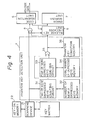
- A key depression data input device according to an embodiment of the present invention is shown in Fig. 4. In the device of Fig. 4,
reference numeral 1 denotes a key matrix in which key contacts are arranged in a matrix-like form, 22 a key-on memory, 21 a scanning device which periodically scans the key matrix and determines whether or not a key or keys have been depressed key. 3 denotes a phantom key detection means, 5 is a release key checking means which whereby, when the phantom keying condition is not realized by releasing a predetermined key among the depressed keys, the check is carried out at the released key, 6 is a code data generation means and 7 is an error warning means. - An embodiment of the present invention shown in Fig. 4 includes detecting means for detecting the generation of a phantom keying condition checking means for checking that a released key among the depressed keys has released the phantom keying condition code generation means for generating normal code data when the released key checked by the checking means corresponds to a key in which a normal depression has been detected.
- The device of Fig. 4 drives the detecting means, checking means, and code generation means, and further, operates the intercept means for informing the operator of the generation of an error when the released key is not been in a normal state.
- Note, the operation of the phantom key detection unit is described in detail in the specification of the preceding Japanese Patent Application No. 61-297249 filed on December 13, 1986 by the same applicant.
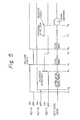
- The operation of the device of Fig. 4 will be explained with reference to Fig. 5.
-
Reference numeral 31 denotes a first counting circuit for producing an output, when more than two newly detected keys are counted during one scan, 33 denotes a second counting circuit for producing an output when a total number of depressed keys is more than four, and 35 denotes an AND circuit. The number of depressed keys is counted by thefirst counter 31. During a time from when the first key has been depressed to a time when the entire key matrix is scanned, when the number of depressed key is "1", and at the same time, the total number of keys depressed is counted by asecond counter 33, and the value of the total number depressed keys counted during depression is also "1", then when the depression of the key is not continued, the code data corresponding to the detected key is output by a code data generation portion (not shown in Fig. 4). Every time a new key is depressed, thecounters counter 31 also counts the phantom key, the counted value becomes "2" and an output is produced. Since the total number of depressed keys is now "4", thesecond counter 33 also produces an output. When the outputs are produced together fromcounters circuit 35 is HIGH and as a result, it is considered that the generation of a phantom key has been detected, the output of the keymatrix scanning device 21 to thecode generation member 6 is stopped by an ANDcircuit 4. - This state is the state at time t₃ in Fig. 5, whereby only a code data corresponding to the depressed key B is produced from the code generation means 6. When key-A is turned off at time t₄ , the
gate 4 sends a voltage variation signal to the releasekey checking circuit 5, and a check is made to determine which of the keys has been released. The output of thecode generation member 6 with respect to the keys is tested, and, the order of the depression and release of the keys is checked. When the key in question is key-C the code data of which has not been produced, and the earlier closed key-A is earlier released, showing the establishment of the normal depression-release order of key operation, a code data for key-C is produced from thecode generation member 6. - When a key C is turned OFF at time t₅ , the output of AND
circuit 35 is not changed. When a key A is turned ON at time t₆ , thecode generation member 6 produces code data for the key A. When the key C is again turned ON at time t₇ , the output of the ANDcircuit 35 is changed to prevent the generation of a new code. When the key C is turned OFF at time t₈ , the release key checking member 60 checks the released key on the basis of the output of thegate 35. If it is acknowledged that key-C, the code data of which has not yet been delivered, is turned OFF, it is determined that the order of the normal depression-release has been reversed, and the releasekey checking circuit 5 drives theerror warning circuit 7 to produce an error warning. - Figure 6 is a flow chart showing the operation of the device. After the process of a
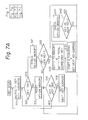
scanning device 21 is started, a key depression is detected in step S1 and code data produced. Then, in step S2, it is determined whether or not a phantom key condition exists. When a phantom key condition does not exist, the process returns to step S1 and stands by for the next key depression. When a phantom key condition does exist, the device detects in step S3 whether the phantom key condition has been released. The process then waits until the phantom key condition has been cancelled, and then proceeds to step S4 to check the state of the released key by determining whether or not code data has been generated. When code data has not been generated, an error signal is produced and output in step S5. - Figure 7 is a flow chart showing in detail the operation of the device according to the present invention.
- After a key scan is carried out, a key address is initially set in step S11 and the crosspoint of each key is identified. In step S12, it is determined whether or not the key is ON, and if not, a key-ON memory is reset in step S13. Then, in step S14, it is determined whether or not the key is the last key. When NO, the step proceeds to the step S15 and the next key address is set. When YES, the process returns to step S11, and the signal output at S15 is sent to step S12.
- In Step S12, when YES, then in step S21 a key-ON memory is checked, and in step S22, it is determined whether the key is a newly depressed key. When YES, in step S23, "1" is set to the
memory 1 of new key and the total number of depressed keys is set to the memory. Then, in step S24, a scanning is started and a next key address is set, where a scanning is commenced from No. 6 key. - Then, in step S25, it is determined whether the key is ON, and in step S26, it is determined whether the one scanning is terminates. When YES, the process returns to step S24.
- In step S27, the new key count memory is checked, and in step S28, it is determined whether the total number of new keys is equal to or larger than 2. When YES, the total key count memory is checked in step S29, and then in step S30, it is determined whether the number of the total number of keys is equal to or larger than four. Then, in step S31, it is determined whether a by-pass or detour flag is ON, and when NO, a by-pass flag is set in step S32. When YES, in step S31, it is determined at step S33 whether the total number of new keys in preceding scan is larger than the total number of new keys in the present scan. When YES, error data is delivered in step S34 and the process returned to step S23.
- In step S30 when the result is NO, the process goes to step S51 and it is determined whether the detour flag is ON. Then, in step S52, key data is sent and a key-on memory is set.
- When YES, at step S51, it is determined whether or not a newly depressed key exists, i.e., the total number of newly depressed keys is equal to or larger than 1, and when NO in step S55, error data is delivered and a detour flag is made OFF. Conversely, when YES, in step S53, key data is delivered, the key-on memory is made ON, and the detour flag is made OFF.
- When NO, in step S53, a newly depressed key (key data is not get delivered) is released to cancel a detour, i.e., the phantom switching condition is cancelled. When YES in step S53, the key for delivering the key data is released to cancel a detour or the phantom switching condition.
Claims (6)
phantom key detection means for detecting an occurrence of phantom key state; and
key release checking means for checking a released key among depressed keys, the releasing of said released key causing a cancellation of the phantom key state;
code data corresponding to the depressed keys being generated and delivered when said key release checking means detects that said released key is the key satisfying a predetermined depression-release sequence condition;
an error warning being delivered when said key release checking means detects that said released key is not the key satisfying the predetermined depression-release sequence condition.
Applications Claiming Priority (2)
| Application Number | Priority Date | Filing Date | Title |
|---|---|---|---|
| JP65309/87 | 1987-03-19 | ||
| JP62065309A JPS63229513A (en) | 1987-03-19 | 1987-03-19 | Key input device |
Publications (3)
| Publication Number | Publication Date |
|---|---|
| EP0283404A2 true EP0283404A2 (en) | 1988-09-21 |
| EP0283404A3 EP0283404A3 (en) | 1990-04-04 |
| EP0283404B1 EP0283404B1 (en) | 1994-03-09 |
Family
ID=13283177
Family Applications (1)
| Application Number | Title | Priority Date | Filing Date |
|---|---|---|---|
| EP88400662A Expired - Lifetime EP0283404B1 (en) | 1987-03-19 | 1988-03-18 | Key-depression data input device |
Country Status (5)
| Country | Link |
|---|---|
| US (1) | US4918444A (en) |
| EP (1) | EP0283404B1 (en) |
| JP (1) | JPS63229513A (en) |
| KR (1) | KR910006695B1 (en) |
| DE (1) | DE3888218T2 (en) |
Cited By (2)
| Publication number | Priority date | Publication date | Assignee | Title |
|---|---|---|---|---|
| EP0651509A1 (en) * | 1993-10-27 | 1995-05-03 | Hydrometer Gesellschaft mbH | Input device |
| EP1078822A2 (en) * | 1999-08-20 | 2001-02-28 | Robert Bosch Gmbh | Keyboard |
Families Citing this family (8)
| Publication number | Priority date | Publication date | Assignee | Title |
|---|---|---|---|---|
| US5059974A (en) * | 1989-02-02 | 1991-10-22 | Acer Incorporated | Method for determining phantom switch condition |
| JPH0769762B2 (en) * | 1991-12-04 | 1995-07-31 | 株式会社アスキー | Method and apparatus for determining simultaneous and sequential keystrokes |
| US5621402A (en) * | 1993-07-21 | 1997-04-15 | Advanced Micro Devices, Inc. | Keypad scanner |
| JPH07230848A (en) * | 1994-02-18 | 1995-08-29 | Nichifu Co Ltd | Connector for conductive linear body |
| US5557299A (en) * | 1994-05-04 | 1996-09-17 | Kidtech, Inc. | Method and apparatus for a learning styled computer keyboard |
| DE19735278A1 (en) * | 1997-08-14 | 1999-02-18 | Rolf Wadewitz | Data acquisition and processing system |
| US6417787B1 (en) * | 1999-08-24 | 2002-07-09 | United Microelectronics Corp. | Method and apparatus for increasing the number of keys of a key-matrix |
| US7224344B2 (en) * | 2003-08-05 | 2007-05-29 | International Business Machines Corporation | Key code filter apparatus and method |
Citations (1)
| Publication number | Priority date | Publication date | Assignee | Title |
|---|---|---|---|---|
| US4420744A (en) * | 1981-02-12 | 1983-12-13 | Oak Industries Inc. | Keyboard crosspoint encoder having N-key rollover |
Family Cites Families (7)
| Publication number | Priority date | Publication date | Assignee | Title |
|---|---|---|---|---|
| US4106011A (en) * | 1975-10-24 | 1978-08-08 | Tektronix, Inc. | Keyboard circuit |
| JPS5266328A (en) * | 1975-11-29 | 1977-06-01 | Casio Comput Co Ltd | Information inputting controller |
| JPS5477534A (en) * | 1977-12-02 | 1979-06-21 | Matsushita Electric Ind Co Ltd | Digital input circuit |
| JPS58112129A (en) * | 1981-12-24 | 1983-07-04 | Tokyo Electric Co Ltd | Key signal input system for 1-chip microcomputer |
| JPS6083132A (en) * | 1983-10-14 | 1985-05-11 | Toshiba Corp | Reader for matrix-shaped switch group |
| JPS62160520A (en) * | 1986-01-08 | 1987-07-16 | Brother Ind Ltd | Matrix switch device |
| JPS63149717A (en) * | 1986-12-13 | 1988-06-22 | Fujitsu Ltd | Detecting system for depressed key |
-
1987
- 1987-03-19 JP JP62065309A patent/JPS63229513A/en active Granted
-
1988
- 1988-03-18 DE DE3888218T patent/DE3888218T2/en not_active Expired - Fee Related
- 1988-03-18 KR KR1019880002864A patent/KR910006695B1/en not_active IP Right Cessation
- 1988-03-18 EP EP88400662A patent/EP0283404B1/en not_active Expired - Lifetime
- 1988-03-18 US US07/169,889 patent/US4918444A/en not_active Expired - Lifetime
Patent Citations (1)
| Publication number | Priority date | Publication date | Assignee | Title |
|---|---|---|---|---|
| US4420744A (en) * | 1981-02-12 | 1983-12-13 | Oak Industries Inc. | Keyboard crosspoint encoder having N-key rollover |
Cited By (3)
| Publication number | Priority date | Publication date | Assignee | Title |
|---|---|---|---|---|
| EP0651509A1 (en) * | 1993-10-27 | 1995-05-03 | Hydrometer Gesellschaft mbH | Input device |
| EP1078822A2 (en) * | 1999-08-20 | 2001-02-28 | Robert Bosch Gmbh | Keyboard |
| EP1078822A3 (en) * | 1999-08-20 | 2004-08-25 | Robert Bosch Gmbh | Keyboard |
Also Published As
| Publication number | Publication date |
|---|---|
| DE3888218T2 (en) | 1994-06-16 |
| KR910006695B1 (en) | 1991-08-31 |
| JPH0511327B2 (en) | 1993-02-15 |
| EP0283404A3 (en) | 1990-04-04 |
| JPS63229513A (en) | 1988-09-26 |
| EP0283404B1 (en) | 1994-03-09 |
| KR880011643A (en) | 1988-10-29 |
| DE3888218D1 (en) | 1994-04-14 |
| US4918444A (en) | 1990-04-17 |
Similar Documents
| Publication | Publication Date | Title |
|---|---|---|
| US4106011A (en) | Keyboard circuit | |
| EP0283404B1 (en) | Key-depression data input device | |
| EP0011307A2 (en) | Method and apparatus for character code generation | |
| JPH0556690B2 (en) | ||
| US4398181A (en) | Keyboard entry system | |
| JPH0348180A (en) | Fast detector for switching condition | |
| US5072366A (en) | Data crossbar switch | |
| US4888600A (en) | Keyboard arrangement with ghost key condition detection | |
| EP0097816B1 (en) | Automatically adjusted delay function for timed repeat character capability of a keyboard | |
| US6417787B1 (en) | Method and apparatus for increasing the number of keys of a key-matrix | |
| US4193038A (en) | Key input apparatus | |
| US5059974A (en) | Method for determining phantom switch condition | |
| NL8002671A (en) | SIGNAL MEASURING DEVICE. | |
| US4437094A (en) | System for controlling indicators for switches | |
| US3803592A (en) | Keyboard and digital circuit therefor | |
| JPH0426129B2 (en) | ||
| JPS609288B2 (en) | character input device | |
| JPS63149717A (en) | Detecting system for depressed key | |
| GB2111275A (en) | Tablet input apparatus | |
| KR0133020B1 (en) | Test pattern generating circuit of a laser printer | |
| US3996560A (en) | Sequencing unit | |
| JPH0470647B2 (en) | ||
| KR20000032636A (en) | Apparatus for inputting multi signal | |
| CA1333924C (en) | Keyboard | |
| SU935951A1 (en) | Pseudorandom number generator |
Legal Events
| Date | Code | Title | Description |
|---|---|---|---|
| PUAI | Public reference made under article 153(3) epc to a published international application that has entered the european phase |
Free format text: ORIGINAL CODE: 0009012 |
|
| AK | Designated contracting states |
Kind code of ref document: A2 Designated state(s): DE FR GB NL |
|
| PUAL | Search report despatched |
Free format text: ORIGINAL CODE: 0009013 |
|
| AK | Designated contracting states |
Kind code of ref document: A3 Designated state(s): DE FR GB NL |
|
| 17P | Request for examination filed |
Effective date: 19900922 |
|
| 17Q | First examination report despatched |
Effective date: 19920728 |
|
| GRAA | (expected) grant |
Free format text: ORIGINAL CODE: 0009210 |
|
| AK | Designated contracting states |
Kind code of ref document: B1 Designated state(s): DE FR GB NL |
|
| REF | Corresponds to: |
Ref document number: 3888218 Country of ref document: DE Date of ref document: 19940414 |
|
| ET | Fr: translation filed | ||
| PLBE | No opposition filed within time limit |
Free format text: ORIGINAL CODE: 0009261 |
|
| STAA | Information on the status of an ep patent application or granted ep patent |
Free format text: STATUS: NO OPPOSITION FILED WITHIN TIME LIMIT |
|
| 26N | No opposition filed | ||
| REG | Reference to a national code |
Ref country code: GB Ref legal event code: IF02 |
|
| PGFP | Annual fee paid to national office [announced via postgrant information from national office to epo] |
Ref country code: FR Payment date: 20040309 Year of fee payment: 17 |
|
| PGFP | Annual fee paid to national office [announced via postgrant information from national office to epo] |
Ref country code: NL Payment date: 20040310 Year of fee payment: 17 |
|
| PGFP | Annual fee paid to national office [announced via postgrant information from national office to epo] |
Ref country code: GB Payment date: 20040317 Year of fee payment: 17 |
|
| PGFP | Annual fee paid to national office [announced via postgrant information from national office to epo] |
Ref country code: DE Payment date: 20040325 Year of fee payment: 17 |
|
| PG25 | Lapsed in a contracting state [announced via postgrant information from national office to epo] |
Ref country code: GB Free format text: LAPSE BECAUSE OF NON-PAYMENT OF DUE FEES Effective date: 20050318 |
|
| PG25 | Lapsed in a contracting state [announced via postgrant information from national office to epo] |
Ref country code: NL Free format text: LAPSE BECAUSE OF NON-PAYMENT OF DUE FEES Effective date: 20051001 Ref country code: DE Free format text: LAPSE BECAUSE OF NON-PAYMENT OF DUE FEES Effective date: 20051001 |
|
| GBPC | Gb: european patent ceased through non-payment of renewal fee |
Effective date: 20050318 |
|
| PG25 | Lapsed in a contracting state [announced via postgrant information from national office to epo] |
Ref country code: FR Free format text: LAPSE BECAUSE OF NON-PAYMENT OF DUE FEES Effective date: 20051130 |
|
| NLV4 | Nl: lapsed or anulled due to non-payment of the annual fee |
Effective date: 20051001 |
|
| REG | Reference to a national code |
Ref country code: FR Ref legal event code: ST Effective date: 20051130 |