EP0288544B1 - A disk cassette loading/unloading mechanism with flexible shutter opening device - Google Patents
A disk cassette loading/unloading mechanism with flexible shutter opening device Download PDFInfo
- Publication number
- EP0288544B1 EP0288544B1 EP87907642A EP87907642A EP0288544B1 EP 0288544 B1 EP0288544 B1 EP 0288544B1 EP 87907642 A EP87907642 A EP 87907642A EP 87907642 A EP87907642 A EP 87907642A EP 0288544 B1 EP0288544 B1 EP 0288544B1
- Authority
- EP
- European Patent Office
- Prior art keywords
- cassette
- disk
- holder
- abutment member
- loading
- Prior art date
- Legal status (The legal status is an assumption and is not a legal conclusion. Google has not performed a legal analysis and makes no representation as to the accuracy of the status listed.)
- Expired - Lifetime
Links
Images


Classifications
-
- G—PHYSICS
- G11—INFORMATION STORAGE
- G11B—INFORMATION STORAGE BASED ON RELATIVE MOVEMENT BETWEEN RECORD CARRIER AND TRANSDUCER
- G11B17/00—Guiding record carriers not specifically of filamentary or web form, or of supports therefor
- G11B17/02—Details
- G11B17/04—Feeding or guiding single record carrier to or from transducer unit
- G11B17/041—Feeding or guiding single record carrier to or from transducer unit specially adapted for discs contained within cartridges
- G11B17/043—Direct insertion, i.e. without external loading means
- G11B17/0438—Direct insertion, i.e. without external loading means with mechanism for subsequent vertical movement of the disc and opening mechanism of the cartridge shutter
-
- G—PHYSICS
- G11—INFORMATION STORAGE
- G11B—INFORMATION STORAGE BASED ON RELATIVE MOVEMENT BETWEEN RECORD CARRIER AND TRANSDUCER
- G11B17/00—Guiding record carriers not specifically of filamentary or web form, or of supports therefor
- G11B17/02—Details
- G11B17/022—Positioning or locking of single discs
- G11B17/028—Positioning or locking of single discs of discs rotating during transducing operation
- G11B17/035—Positioning by moving the loading station
Definitions
- This invention relates to a disk cassette loading/unoading mechanism for use in a disk cassette recorder or the like having a disk drive mechanism, wherein the disk cassette includes a record disk within the cassette, a leading end portion having front and rear edges, an aperture in the cassette extending to the front edge for insertion therethrough of magnetic heads, and a shutter blade associated with the aperture and movable between an aperture-open position and an aperture-closed position.
- the disk cassette is of the type comprising a cassette housing containing a flexible magnetic disk.
- the magnetic disk is rotated at a high speed within the cassette housing, and at the same time a magnetic head is brought into contact with a magnetic surface of the magnetic disk while being moved in a radial direction of the magnetic disk to record or reproduce video, audio, or digital signals.
- the disk cassette is held by a cassette holder and is moved together with the holder from a loading/unloading position to a recording position. When the disk cassette has been moved into the recording position, the magnetic head comes into contact with the magnetic surface of the magnetic disk to perform the recording or reproducing.
- a cassette holder comprises a support plate with abutment means for opening the shutter during insertion of the cassette into the holder.
- the abutment means are disengaged from the closed shutter as the cassette is being ejected.
- a serious problem presented by such cassette loading/unloading mechanisms is that in those situations in which the cassette or cassette holder are non-planar due to warping, bending or the like, it is possible for the shutter opening apparatus to malfunction due to improper engagement or disengagement of the cassette and shutter opening components of the mechanism. This can result in a failure to open the cassette shutter or shutter blades, and a consequent failure of the recording process and possible damage to the magnetic head assembly and other recorder components.
- this object is attained by a disc cassette loading/unloading mechanism according to claim 1.
- the base portion has a bevelled undersurface at one end thereof such that when the one end is secured to the support plate, a torque is applied to the base portion forcing the rib into a slot in the support plate.
- the other two legs of the support member have one of the ends thereof connected to ends of the base portion, and the other ends of the two legs are connected together and support the abutment member.
- the two legs are inclined upwardly from the base portion partly into the path of the cassette, and further define an angle ⁇ with the horizontal of about 12 degrees.
- the primary object and advantage of the present invention is to provide a disk cassette loading/unloading mechanism for use in a disk cassette recorder or the like in which possible malfunctioning of the cassette shutter opening apparatus is eliminated.
- the mechanism is further of simple design and construction, thoroughly reliable and efficient in operation, and economical to manufacture.
- a preferred embodiment of the disk cassette loading/unloading mechanism of this invention broadly comprises a support base 10, shown in Fig. 1, onto which a disk drive mechanism 12 is mounted.
- the mechanism further comprises a disk cassette holder 14, shown in Fig. 2, pivotally mounted on the support base about pivots 16, as shown in Fig. 3.
- a disk cassette 18, described later in connection with Figs. 4-5, is of the type comprising a cassette housing 20 containing a flexible magnetic disk 22 or the like.
- the cassette holder 14 is pivotally movable between a loading/unloading position (Fig. 3), in which the cassette 18 can be inserted into the holder 14 to a loaded position or unloaded from the holder 14 from the loaded position, and a disk recording position (Fig.
- cassette 18 in which disk 22 in cassette 18 can be drivingly engaged by disk drive mechanism 12.
- the leading edge or end 24 of the cassette 18 cocks a cassette ejecting mechanism 26 (Fig. 1) and actuates a cassette holder supporting means 28 (Fig. 1) to release holder 14 for movement of disk cassette 18 to the disk recording position.
- the cassette 18 is unloaded from the disk cassette loading/unloading mechanism by pressing a cassette ejection button 30. Inward movement of the button 30 pivotally moves cassette holder 14 to its cassette loading/unloading position, and then releases the cassette ejection mechanism 26 which unloads cassette 18 by ejecting it at least partially out of the cassette holder 14.
- support base 10 comprises a unitary casting of aluminum or the like.
- the base 10 has front and rear horizontal, vertically spaced plates 32, 34 respectively, the opposite edges of which are integral with upstanding side plates 36.
- the lower rear plate 34 supports a pair of steel cylindrical rails 38 in parallel spaced relation onto which a magnetic head assembly 40 is slideably mounted.
- the upper front plate 32 supports disk drive mechanism 12 on its undersurface, and further has a circular opening 42 through which a drive plate 44 of the disk drive mechanism 12 extends for drivingly engaging the hub, not shown, of a magnetic disk 22.
- the front plate 32 further pivotally supports first, second and third levers 46, 48, 50 respectively on its undersurface comprising a part of the disk cassette ejecting mechanism 26 and a part of the mechanism 28 for releasably supporting disk cassette holder 14 in its loading/unloading position.
- the first lever 46 is pivoted on pivot 52 for either supporting or releasing holder 14 as will be explained later.
- the second lever 48 is pivoted on pivot 54 and couples the first and second levers 46, 48 together.
- the third lever 50 is pivoted on pivot 56, and when it is cocked controls pivotal movement of first lever 46 for releasing cassette holder 14 for movement to the recording position. When third lever 50 is released, it ejects a cassette 18 at least partially out of holder 14.
- the first and second levers 46, 48 respectively are coupled together by an integral spring arm 58 on first lever 46 engaging a lip 60 on second lever 48 for urging a depending pin 62 on first lever 46 into engagement with a lug 64 on second lever 48, as best seen in Figs. 1, 8 and 9.
- the second lever 48 is biased in a clockwise direction by a helical spring 66 having one end connected to front plate 32 and its opposite end connected to second lever 48.
- An end of second lever 48 has an arcuate surface 68 that is biased by spring 66 into engagement with a lug 70 on one end of third lever 50.
- the arcuate surface 68 is concentric to pivot 56 such that pivotal movement of third lever 50 will not change the position of second lever 48 until lug 70 reaches a notch 72 at the end of arcuate surface 68.
- second lever 48 is moved clockwise capturing third lever 50 in its latched or cocked position (see Fig. 5) as lug 70 nests in notch 72.
- Such movement of second lever 48 pivots first lever 46 which releases cassette holder 14 in a manner to be explained herinafter for movement to the recording position.
- the front plate 32 further slideably supports disk cassette ejection button 30 for reciprocal movement on spaced rails 76 between a normal retracted position and a cassette ejection position.
- the ejection button 30 has an end surface on an outwardly extending finger 78 for engaging pin 62 on first lever 46 and pivotally moving the first and second levers 46, 48 to a position releasing the cocked third lever 50 upon manual inward movement of the cassette ejection button 30.
- the ejection button 30 is held in its normal retracted position by a leaf spring 80 having one end secured to plate 32 and its free end bearing against the button 30.
- disk cassette holder 14 comprises a plate member 82 having opposite parallel U-shaped channel members 84 for slideably receiving edges of a disk cassette 18 inserted therein.
- the holder 14 has a stop lip 86 to limit insertion of disk cassette 18 to its loaded position.
- the plate member 82 has a circular opening 88 in register with opening 42 in support plate 32 for aligning a disk hub, not shown, in cassette 18 with drive plate 44.
- the cassette and disk hub are described in detail in International Application PCT/US 86/02376, filed November 6, 1986 by the same assignee, now PCT Publication WO 87/03134.
- cassette holder 14 is shown pivotally secured to support base 10 on pivots 16 for pivotal movement between a normal loading/unloading position, as seen in Figs. 3 and 6, and a recording position, as seen in Figs. 5 and 7.
- the pivots 16 comprise laterally extending spindles on the inner surface of side plates 36 extending into openings in the inner ends of channel members 84.
- the cassette holder 14 is maintained in its normal loading/unloading position by a depending finger 90 on a boss 92 (see Figs. 2 and 6) secured to the undersurface of plate 82.
- the first lever 46 defines an opening 94 (Fig. 1) extending therethrough, and finger 90 rests on a portion 96 of first lever 46 extending between an edge of opening 94 and an outer edge 98 of the first lever 46.
- front support plate 32 further supports an abutment member 100 which is adapted when a disk cassette 18 is inserted into holder 14 to engage a shutter blade 102, as shown in Fig. 4a, for moving the shutter blades 102 from their aperture-closed position to their aperture-open position, as shown in Fig. 5. Since the disk cassette 18 is described in detail in the aforementioned PCT Publication WO 87/03134, only portions thereof pertinent to this invention will be shown and described.
- disk cassette 18 has a bottom half 104 provided with a rectangularly shaped opening 106 that extends to the front edge 24 of the cassette 18 to permit entry into the opening of abutment member 100.
- the front edge 24 of the top half of the cassette 18 has a lower surface 110 provided with a depending lug 112 for engaging the upper surface of lower shutter blade 102.
- the lug 112 separates shutter blade 102 from surface 110 to form a gap therebetween for receiving a lip 114 of abutment member 100.
- the gap and lip 114 cooperate to assure engagement of abutment member 100 with an outer surface means or edge of shutter blade 102.
- Lip 114 enters the gap upon inward movement of the cassette 18 and captures the shutter blade 102 between the lip and a stem 116 of abutment member 100 to prevent the shutter blade 102 from riding over the top of the abutment member 100.
- Cassette edge 24 has a bevelled portion 118 to assist entry of Lip 114 into the gap. Further movement of abutment member 100 into the cassette 18 upon movement of the cassette 18 to the position shown in Fig. 5 is effective to move the shutter blades 102, which are secured together, to their aperture-open position.
- abutment member 100 is formed as an integral part of a support member 120.
- the abutment and support members (100, 120) are integrally formed by any suitable molding process from any suitable material, such as nylon, for example.
- the lip 114 on the leading end of abutment member 100 has an arcuate shape having a radius of .059 inch (0,15 cm).
- the trailing end of abutment member 100 has a flat downwardly bevelled surface 130 at an angle ⁇ of approximately 25 degrees to prevent the abutment member 100 from catching on a sharp edge 132 of the cassette 18 when it is ejected or removed from holder 14, as best seen in Fig. 4b.
- the support member 120 is flexible, spring-like and triangularly shaped and essentially formed of three legs.
- One leg comprises a base portion 121 by which the support member 120 is secured to upper plate 32.
- Base position 121 has a bore 123 at one corner having a central opening 125 through which a screw 127 extends for securing support member 120 to plate 32.
- Base portion 121 further has an elongated rectangular depending rib 129, as best seen in Fig. 3d, that nests in a complementary slot 131 in upper plate 32 to prevent the support member 120 from pivoting about the screw 127 during shutter opening operations.
- the lower surface of the corner forms an angle to the horizontal of about 3 degrees so that when screw 127 is tightened, the corner bends and applies torque to base portion 121 in a direction forcing rib 129 tightly into slot 131.
- the support member 120 further comprises two legs 133, 135 normally inclined upwardly at an angle to the horizontal of about 12 degrees, as best seen in Figs. 3b and 3d.
- One of the ends of the two legs 133, 135 are integral with end portions of base portion 121, and the opposite ends are joined together at a corner for supporting abutment member 100.
- the loading/unloading mechanism is shown in its recording position in which cassette shutter blades 102 are opened and disk hub is in driving engagement with drive plate 44.
- This position is achieved by inserting a disk cassette 18 through the outer open end of holder 14 in its loading/unloading position (see Figs. 3 and 6), and slideably moving the cassette 18 therealong into its loaded position.
- Initial movement of the cassette 18 causes the leading edge 24 thereof to engage inclined legs 133, 135, as seen in phantom in Fig. 3b, and cam the legs 133, 135 downwardly into the position seen in Fig. 4c, in which abutment member 100 engages the outer end of shutter blade 102.
- first lever 46 moves portion 96 thereof out from under depending finger 90 on holder plate 82 causing the finger 90 to drop through opening 94 in first lever 46, as best seen in Fig. 7.
- the holder 14 and disk cassette 18 contained therein drops along with finger 90 into a recording position.
- disk cassette 18 is precisely oriented by holder plate spindles 16, and a pair of locating pins 134 (Fig. 1) on front plate 32 passing through openings in holder plate 82 and into engagement with blind bores, not shown, in the cassette 18.
- third lever 50 is moved to its cocked position, the opposite end 136 thereof engages a lip 138 (Figs.
- levers 148, 150 are pivoted about pivots 154, 156 respectively with a short end 155 of lever 148 extending through a slot 158 in channel member 84, and its opposite long end bearing against a short arm on lever 150.
- the longer end of lever 150 has a laterally extending finger 160 for engaging a surface on upper head 144 to force it downwardly under the influence of spring 152 into a recording position when cassette holder 14 is moved to its recording position.
- levers 148, 150 are moved into their full line position, shown in Fig. 3a, allowing spring 152 to retract finger 160 and upper head 144 to retract from the disk 22.
- cassette ejection button 30 when it is desired to unload cassette 18 following a disk recording operation, cassette ejection button 30 is manually pressed inwardly. Initial movement of the button 30 causes a bevelled surface 162 thereon to engage a bevelled surface 164 on cassette holder boss 92 and to cam cassette holder 14 pivotally upwardly withdrawing depending finger 90 from opening 94 in first lever 46. When finger 90 clears the opening, continued inward movement of ejection button 30 pivots the first and second levers 46, 48 respectively in a counterclockwise direction causing portion 96 of first lever 46 to move under depending finger 90. At substantially that moment, third lever lug 70 clears notch 72 (Fig.
Abstract
Description
- This invention relates to a disk cassette loading/unoading mechanism for use in a disk cassette recorder or the like having a disk drive mechanism, wherein the disk cassette includes a record disk within the cassette, a leading end portion having front and rear edges, an aperture in the cassette extending to the front edge for insertion therethrough of magnetic heads, and a shutter blade associated with the aperture and movable between an aperture-open position and an aperture-closed position.
- Recording and/or reproducing apparatus of the type in which a disk cassette is loaded into and unloaded from the apparatus are well known in the art. The disk cassette is of the type comprising a cassette housing containing a flexible magnetic disk. In such a conventional recording and/or reproducing apparatus, the magnetic disk is rotated at a high speed within the cassette housing, and at the same time a magnetic head is brought into contact with a magnetic surface of the magnetic disk while being moved in a radial direction of the magnetic disk to record or reproduce video, audio, or digital signals. Usually the disk cassette is held by a cassette holder and is moved together with the holder from a loading/unloading position to a recording position. When the disk cassette has been moved into the recording position, the magnetic head comes into contact with the magnetic surface of the magnetic disk to perform the recording or reproducing.
- In a known disk cassette loading/unloading mechanism, as described in GB-
A-2 155 233, a cassette holder comprises a support plate with abutment means for opening the shutter during insertion of the cassette into the holder. - According to another mechanism of this type the abutment means are disengaged from the closed shutter as the cassette is being ejected.
- These known disk cassette mechanisms are of complicated design and construction, containing many interacting parts requiring a high degree of precision in manufacture in order for the mechanisms to operate properly.
- A serious problem presented by such cassette loading/unloading mechanisms is that in those situations in which the cassette or cassette holder are non-planar due to warping, bending or the like, it is possible for the shutter opening apparatus to malfunction due to improper engagement or disengagement of the cassette and shutter opening components of the mechanism. This can result in a failure to open the cassette shutter or shutter blades, and a consequent failure of the recording process and possible damage to the magnetic head assembly and other recorder components.
- It is the object of the present invention to provide a cassette loading/unloading mechanism of the generic type which is of simple design and construction, thoroughly reliable and efficient in operation, and economical to manufacture.
- In accordance with the invention, this object is attained by a disc cassette loading/unloading mechanism according to claim 1.
- The base portion has a bevelled undersurface at one end thereof such that when the one end is secured to the support plate, a torque is applied to the base portion forcing the rib into a slot in the support plate. The other two legs of the support member have one of the ends thereof connected to ends of the base portion, and the other ends of the two legs are connected together and support the abutment member. The two legs are inclined upwardly from the base portion partly into the path of the cassette, and further define an angle β with the horizontal of about 12 degrees.
- Accordingly, the primary object and advantage of the present invention is to provide a disk cassette loading/unloading mechanism for use in a disk cassette recorder or the like in which possible malfunctioning of the cassette shutter opening apparatus is eliminated. The mechanism is further of simple design and construction, thoroughly reliable and efficient in operation, and economical to manufacture.
- Other objects and advantages of the invention will become apparent from the following detailed description taken in connection with the accompanying drawings.
- In the detailed description of the invention presented below, reference is made to the accompanying drawings, in which:
- Fig. 1 is a top plan view of the support plate of the disk cassette loading/unloading mechanism with a portion thereof broken away, and further showing a shutter opening abutment means in phantom;
- Fig. 2 is a top plan view of the disk cassette holder with a portion thereof broken away showing the boss secured thereto;
Fig. 3 is a top plan view of the disk cassette loading/unloading mechanism in its loading/unloading position, and also showing the magnetic head assembly and head assembly moving means; - Fig. 3a is a segmental view of the upper magnetic head moving mechanism taken substantially from line 3a-3a of Fig. 3;
- Fig. 3b is a front elevation view of the abutment means shown in Fig. 3;
- Fig. 3c is a right side elevation view of the base portion of the abutment means of Fig. 3b with the remaining legs omitted;
- Fig. 3d is a bottom view of the abutment means of Fig. 3b;
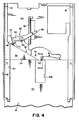
- Fig. 4 is a top plan view of the disk cassette loading/unloading mechanism in its loading/unloading position showing a disk cassette inserted into the holder until the leading edge thereof engages a shutter opening abutment member;
- Fig. 4a is a segmental greatly enlarged section view taken substantlally along line 4a-4a of Fig. 4;
- Fig. 4b is a segmental greatly enlarged view similar to Fig. 4a showing the cassette passing over the abutment member as it is ejected from the holder;
- Fig. 4c is a segmental greatly enlarged view taken substantially from
line 4c-4c of Fig. 4; - Fig. 5 is a top plan view of the disk cassette loading/unloading mechanism in a recording position, and showing the disk cassette in its loaded position with the cassette shutter blades in an open position;
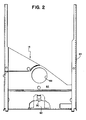
- Fig. 6. is a section view taken substantially along line 6-6 of Fig. 3 showing the holder in its loading/unloading position with portions thereof omitted for purposes of clarity;
- Fig. 7 is a section view taken substantially along line 7-7 of Fig. 5 showing the holder in its recording position with portions thereof omitted for purposes of clarity;
- Fig. 8 is a segmental top plan view taken substantially from line 8-8 of Fig. 9 showing the eject button pressed inwardly for moving the holder to its loading/unloading position end the cassette ejection mechanism about to be released; end
- Fig. 9 is a view taken substantially from line 9-9 of Fig. 8.
- Referring now to Figs. 1-3, a preferred embodiment of the disk cassette loading/unloading mechanism of this invention broadly comprises a
support base 10, shown in Fig. 1, onto which adisk drive mechanism 12 is mounted. The mechanism further comprises adisk cassette holder 14, shown in Fig. 2, pivotally mounted on the support base aboutpivots 16, as shown in Fig. 3. Adisk cassette 18, described later in connection with Figs. 4-5, is of the type comprising acassette housing 20 containing a flexiblemagnetic disk 22 or the like. Thecassette holder 14 is pivotally movable between a loading/unloading position (Fig. 3), in which thecassette 18 can be inserted into theholder 14 to a loaded position or unloaded from theholder 14 from the loaded position, and a disk recording position (Fig. 5), in whichdisk 22 incassette 18 can be drivingly engaged bydisk drive mechanism 12. When thecassette 18 is manually inserted intoholder 14 to its loaded position, the leading edge orend 24 of thecassette 18 cocks a cassette ejecting mechanism 26 (Fig. 1) and actuates a cassette holder supporting means 28 (Fig. 1) torelease holder 14 for movement ofdisk cassette 18 to the disk recording position. following the disk recording operation, thecassette 18 is unloaded from the disk cassette loading/unloading mechanism by pressing acassette ejection button 30. Inward movement of thebutton 30 pivotally movescassette holder 14 to its cassette loading/unloading position, and then releases thecassette ejection mechanism 26 which unloadscassette 18 by ejecting it at least partially out of thecassette holder 14. - With specific reference to Fig. 1,
support base 10 comprises a unitary casting of aluminum or the like. Thebase 10 has front and rear horizontal, vertically spacedplates upstanding side plates 36. The lowerrear plate 34 supports a pair of steelcylindrical rails 38 in parallel spaced relation onto which amagnetic head assembly 40 is slideably mounted. Theupper front plate 32 supportsdisk drive mechanism 12 on its undersurface, and further has a circular opening 42 through which adrive plate 44 of thedisk drive mechanism 12 extends for drivingly engaging the hub, not shown, of amagnetic disk 22. - The
front plate 32 further pivotally supports first, second andthird levers cassette ejecting mechanism 26 and a part of themechanism 28 for releasably supportingdisk cassette holder 14 in its loading/unloading position. Thefirst lever 46 is pivoted onpivot 52 for either supporting or releasingholder 14 as will be explained later. Thesecond lever 48 is pivoted onpivot 54 and couples the first andsecond levers third lever 50 is pivoted onpivot 56, and when it is cocked controls pivotal movement offirst lever 46 for releasingcassette holder 14 for movement to the recording position. Whenthird lever 50 is released, it ejects acassette 18 at least partially out ofholder 14. - The first and
second levers integral spring arm 58 onfirst lever 46 engaging alip 60 onsecond lever 48 for urging a dependingpin 62 onfirst lever 46 into engagement with alug 64 onsecond lever 48, as best seen in Figs. 1, 8 and 9. Thesecond lever 48 is biased in a clockwise direction by ahelical spring 66 having one end connected tofront plate 32 and its opposite end connected tosecond lever 48. An end ofsecond lever 48 has anarcuate surface 68 that is biased byspring 66 into engagement with alug 70 on one end ofthird lever 50. Thearcuate surface 68 is concentric to pivot 56 such that pivotal movement ofthird lever 50 will not change the position ofsecond lever 48 untillug 70 reaches anotch 72 at the end ofarcuate surface 68. When this occurs,second lever 48 is moved clockwise capturingthird lever 50 in its latched or cocked position (see Fig. 5) aslug 70 nests innotch 72. Such movement ofsecond lever 48 pivotsfirst lever 46 which releasescassette holder 14 in a manner to be explained herinafter for movement to the recording position. - The
front plate 32 further slideably supports diskcassette ejection button 30 for reciprocal movement on spacedrails 76 between a normal retracted position and a cassette ejection position. Theejection button 30 has an end surface on an outwardly extendingfinger 78 for engagingpin 62 onfirst lever 46 and pivotally moving the first andsecond levers third lever 50 upon manual inward movement of thecassette ejection button 30. Theejection button 30 is held in its normal retracted position by aleaf spring 80 having one end secured to plate 32 and its free end bearing against thebutton 30. - With reference to Fig. 2,
disk cassette holder 14 comprises aplate member 82 having opposite parallelU-shaped channel members 84 for slideably receiving edges of adisk cassette 18 inserted therein. Theholder 14 has a stop lip 86 to limit insertion ofdisk cassette 18 to its loaded position. Theplate member 82 has acircular opening 88 in register with opening 42 insupport plate 32 for aligning a disk hub, not shown, incassette 18 withdrive plate 44. The cassette and disk hub are described in detail in International Application PCT/US 86/02376, filed November 6, 1986 by the same assignee, now PCT Publication WO 87/03134. - With reference to Figs. 3, 3a, 5, 6 and 7,
cassette holder 14 is shown pivotally secured to supportbase 10 onpivots 16 for pivotal movement between a normal loading/unloading position, as seen in Figs. 3 and 6, and a recording position, as seen in Figs. 5 and 7. Thepivots 16 comprise laterally extending spindles on the inner surface ofside plates 36 extending into openings in the inner ends ofchannel members 84. Thecassette holder 14 is maintained in its normal loading/unloading position by a dependingfinger 90 on a boss 92 (see Figs. 2 and 6) secured to the undersurface ofplate 82. Thefirst lever 46 defines an opening 94 (Fig. 1) extending therethrough, andfinger 90 rests on aportion 96 offirst lever 46 extending between an edge of opening 94 and anouter edge 98 of thefirst lever 46. - With reference to Figs. 1, 4 and 5,
front support plate 32 further supports anabutment member 100 which is adapted when adisk cassette 18 is inserted intoholder 14 to engage ashutter blade 102, as shown in Fig. 4a, for moving theshutter blades 102 from their aperture-closed position to their aperture-open position, as shown in Fig. 5. Since thedisk cassette 18 is described in detail in the aforementioned PCT Publication WO 87/03134, only portions thereof pertinent to this invention will be shown and described. - With specific reference to Figs. 4, 4a, 4b and 4c,
disk cassette 18 has abottom half 104 provided with a rectangularly shaped opening 106 that extends to thefront edge 24 of thecassette 18 to permit entry into the opening ofabutment member 100. Thefront edge 24 of the top half of thecassette 18 has alower surface 110 provided with a dependinglug 112 for engaging the upper surface oflower shutter blade 102. Thelug 112 separates shutterblade 102 fromsurface 110 to form a gap therebetween for receiving alip 114 ofabutment member 100. The gap andlip 114 cooperate to assure engagement ofabutment member 100 with an outer surface means or edge ofshutter blade 102.Lip 114 enters the gap upon inward movement of thecassette 18 and captures theshutter blade 102 between the lip and astem 116 ofabutment member 100 to prevent theshutter blade 102 from riding over the top of theabutment member 100.Cassette edge 24 has a bevelledportion 118 to assist entry ofLip 114 into the gap. further movement ofabutment member 100 into thecassette 18 upon movement of thecassette 18 to the position shown in Fig. 5 is effective to move theshutter blades 102, which are secured together, to their aperture-open position. - More specifically,
abutment member 100 is formed as an integral part of asupport member 120. The abutment and support members (100, 120) are integrally formed by any suitable molding process from any suitable material, such as nylon, for example. Thelip 114 on the leading end ofabutment member 100 has an arcuate shape having a radius of .059 inch (0,15 cm). The trailing end ofabutment member 100 has a flat downwardlybevelled surface 130 at an angle α of approximately 25 degrees to prevent theabutment member 100 from catching on asharp edge 132 of thecassette 18 when it is ejected or removed fromholder 14, as best seen in Fig. 4b. - Referring now to Figs. 1, 3, 3b, 3c and 3d, the
support member 120 is flexible, spring-like and triangularly shaped and essentially formed of three legs. One leg comprises abase portion 121 by which thesupport member 120 is secured toupper plate 32.Base position 121 has abore 123 at one corner having acentral opening 125 through which ascrew 127 extends for securingsupport member 120 to plate 32.Base portion 121 further has an elongated rectangular dependingrib 129, as best seen in Fig. 3d, that nests in acomplementary slot 131 inupper plate 32 to prevent thesupport member 120 from pivoting about thescrew 127 during shutter opening operations. The lower surface of the corner, as best seen in Fig. 3c, forms an angle to the horizontal of about 3 degrees so that whenscrew 127 is tightened, the corner bends and applies torque tobase portion 121 in adirection forcing rib 129 tightly intoslot 131. - The
support member 120 further comprises twolegs legs base portion 121, and the opposite ends are joined together at a corner for supportingabutment member 100. - With reference to Figs. 5 and 7, the loading/unloading mechanism is shown in its recording position in which
cassette shutter blades 102 are opened and disk hub is in driving engagement withdrive plate 44. This position is achieved by inserting adisk cassette 18 through the outer open end ofholder 14 in its loading/unloading position (see Figs. 3 and 6), and slideably moving thecassette 18 therealong into its loaded position. Initial movement of thecassette 18 causes the leadingedge 24 thereof to engageinclined legs legs abutment member 100 engages the outer end ofshutter blade 102. Further movement of thecassette 18 to its loaded position cams theshutter blades 102 into a shutter-open position, as seen in Fig. 5. As thedisk cassette 18 approaches its loading position, the leadingend 24 thereof engages an upwardly extending portion oflug 70 and pivotsthird lever 50 until thelug 70 reachessecond lever notch 72 and bottoms therein, as best seen in Fig. 5. As this occurs,second lever 48 pivots in a clockwise direction under the influence ofspring 66. This, in turn, pivotsfirst lever 46 in a clockwise direction via thespring arm 58 andlip 60 connection which maintainsfirst lever pin 62 into engagement withsecond lever lug 64. Movement offirst lever 46moves portion 96 thereof out from under dependingfinger 90 onholder plate 82 causing thefinger 90 to drop throughopening 94 infirst lever 46, as best seen in Fig. 7. Theholder 14 anddisk cassette 18 contained therein drops along withfinger 90 into a recording position. In this recording position,disk cassette 18 is precisely oriented byholder plate spindles 16, and a pair of locating pins 134 (Fig. 1) onfront plate 32 passing through openings inholder plate 82 and into engagement with blind bores, not shown, in thecassette 18. Also, asthird lever 50 is moved to its cocked position, theopposite end 136 thereof engages a lip 138 (Figs. 1 and 3) onmagnetic head assembly 40 for sliding thehead assembly 40, viarollers 140 riding onsteel ways 38, over the uncovered portion of thedisk 22, with an upper magnetic head 144 (Fig. 3a) biased by a spring, not shown, away from alower head 146.Levers channel members 84 toupper head 144 of themagnetic head assembly 40 causing theupper head 144 to move downwardly under the influence of spring 152 (Fig. 3), upon movement ofcassette holder 14 to the recording position for pinchingdisk 22 between the upper and lowermagnetic heads levers pivots short end 155 oflever 148 extending through aslot 158 inchannel member 84, and its opposite long end bearing against a short arm onlever 150. The longer end oflever 150 has a laterally extendingfinger 160 for engaging a surface onupper head 144 to force it downwardly under the influence ofspring 152 into a recording position whencassette holder 14 is moved to its recording position. As indicated earlier, when thecassette holder 14 is moved to its loading/unloading position, levers 148, 150 are moved into their full line position, shown in Fig. 3a, allowingspring 152 to retractfinger 160 andupper head 144 to retract from thedisk 22. - With reference to Figs. 8 and 9, when it is desired to unload
cassette 18 following a disk recording operation,cassette ejection button 30 is manually pressed inwardly. Initial movement of thebutton 30 causes abevelled surface 162 thereon to engage abevelled surface 164 oncassette holder boss 92 and tocam cassette holder 14 pivotally upwardly withdrawing dependingfinger 90 from opening 94 infirst lever 46. Whenfinger 90 clears the opening, continued inward movement ofejection button 30 pivots the first andsecond levers direction causing portion 96 offirst lever 46 to move under dependingfinger 90. At substantially that moment,third lever lug 70 clears notch 72 (Fig. 5) releasing the cockedthird lever 50 which ejectscassette 18 fromholder 14. Upon release ofejection button 30, spring 80 (Fig. 1) returnsbutton 30 to its normal retracted position. Also, dependingfinger 90 drops down ontoportion 96 offirst lever 46 and is pressed into engagement therewith (see Fig. 6) by a U-shaped wire spring 166 (Fig. 1).Spring 166 has its center section mounted onfront plate 32 and itsends 168 pressing downwardly on ears 170 (Fig. 3) oncassette holder 14.
Claims (10)
Applications Claiming Priority (2)
| Application Number | Priority Date | Filing Date | Title |
|---|---|---|---|
| US06/925,435 US4761698A (en) | 1986-10-31 | 1986-10-31 | Disk cassette loading/unloading mechanism with flexible shutter opening device |
| US925435 | 1986-10-31 |
Publications (2)
| Publication Number | Publication Date |
|---|---|
| EP0288544A1 EP0288544A1 (en) | 1988-11-02 |
| EP0288544B1 true EP0288544B1 (en) | 1991-03-27 |
Family
ID=25451729
Family Applications (1)
| Application Number | Title | Priority Date | Filing Date |
|---|---|---|---|
| EP87907642A Expired - Lifetime EP0288544B1 (en) | 1986-10-31 | 1987-10-22 | A disk cassette loading/unloading mechanism with flexible shutter opening device |
Country Status (4)
| Country | Link |
|---|---|
| US (1) | US4761698A (en) |
| EP (1) | EP0288544B1 (en) |
| JP (1) | JPH01501267A (en) |
| WO (1) | WO1988003313A1 (en) |
Families Citing this family (3)
| Publication number | Priority date | Publication date | Assignee | Title |
|---|---|---|---|---|
| JP2562301B2 (en) * | 1986-05-09 | 1996-12-11 | 株式会社リコー | Disk holding mechanism of disk drive device |
| US4870518A (en) * | 1988-02-26 | 1989-09-26 | Syquest Technology | Removable cartridge disc drive with radial arm voice coil actuator |
| JP3765668B2 (en) * | 1998-06-10 | 2006-04-12 | パイオニア株式会社 | Disc player |
Family Cites Families (6)
| Publication number | Priority date | Publication date | Assignee | Title |
|---|---|---|---|---|
| US3593327A (en) * | 1968-10-24 | 1971-07-13 | Singer Co | Memory-disc cartridge with loading mechanism |
| US4120012A (en) * | 1977-04-18 | 1978-10-10 | Information Terminals Corporation | Diskette door |
| US4414591A (en) * | 1980-06-18 | 1983-11-08 | International Business Machines Corporation | Dual access flexible disk drive |
| US4399480A (en) * | 1981-03-30 | 1983-08-16 | Disctron, Inc. | Head access door, opening mechanism and method of sealing |
| US4412260A (en) * | 1981-04-24 | 1983-10-25 | Magnetic Peripherals Inc. | Cartridge receiver mechanism |
| DE3422136A1 (en) * | 1983-06-15 | 1984-12-20 | Alps Electric Co., Ltd., Tokio/Tokyo | RECORDING AND PLAYING DEVICE FOR MAGNETIC DISK CARTRIDGES |
-
1986
- 1986-10-31 US US06/925,435 patent/US4761698A/en not_active Expired - Lifetime
-
1987
- 1987-10-22 WO PCT/US1987/002699 patent/WO1988003313A1/en active IP Right Grant
- 1987-10-22 JP JP62507019A patent/JPH01501267A/en active Pending
- 1987-10-22 EP EP87907642A patent/EP0288544B1/en not_active Expired - Lifetime
Also Published As
| Publication number | Publication date |
|---|---|
| EP0288544A1 (en) | 1988-11-02 |
| WO1988003313A1 (en) | 1988-05-05 |
| JPH01501267A (en) | 1989-04-27 |
| US4761698A (en) | 1988-08-02 |
Similar Documents
| Publication | Publication Date | Title |
|---|---|---|
| US4965685A (en) | Removable cartridge disc drive with radial arm voice coil actuator | |
| US4870518A (en) | Removable cartridge disc drive with radial arm voice coil actuator | |
| CA1212468A (en) | Disc cassette loading apparatus | |
| US3890643A (en) | Flexible disk drive cartridge loading apparatus | |
| US4685010A (en) | Locking and ejecting device for a recording and reproducing apparatus for magnetic discs | |
| JPS58224480A (en) | Disc driver | |
| US4636890A (en) | Magnetic tape recorder | |
| EP0288544B1 (en) | A disk cassette loading/unloading mechanism with flexible shutter opening device | |
| EP0133312B1 (en) | Data transfer apparatus for use with a flexible magnetic disk or the like | |
| JPS61292261A (en) | Cartridge handler | |
| EP0289555B1 (en) | A disk cassette loading/unloading mechanism with rigid shutter opening device | |
| EP0151240B1 (en) | Guiding and registering multiple sizes of diskettes in a floppy disk drive | |
| JPH01159861A (en) | Device for loading disk cartridge | |
| US4458278A (en) | Disk-centering mechanism for use with a high-density flexible disk | |
| US4755894A (en) | Disk cassette loading/unloading mechanism for use in a disk recorder or the like | |
| US4835638A (en) | Disk cartridge loading and ejecting mechanism in recording/reproducing apparatus | |
| US5355359A (en) | Cartridge ejector of an optical disc player | |
| JPS6235168Y2 (en) | ||
| JP2508582B2 (en) | Disk cassette loading device | |
| CA1336016C (en) | Removal cartridge disc drive with radial arm voice coil actuator | |
| JP2526420B2 (en) | Cassette loading device | |
| JP2521960Y2 (en) | Magnetic disk cartridge attachment / detachment mechanism | |
| JP2553578B2 (en) | Disk drive | |
| JPH073487Y2 (en) | Magnetic disk cartridge loading / unloading mechanism | |
| JP2826033B2 (en) | Cartridge loading device |
Legal Events
| Date | Code | Title | Description |
|---|---|---|---|
| PUAI | Public reference made under article 153(3) epc to a published international application that has entered the european phase |
Free format text: ORIGINAL CODE: 0009012 |
|
| 17P | Request for examination filed |
Effective date: 19880701 |
|
| AK | Designated contracting states |
Kind code of ref document: A1 Designated state(s): BE DE FR GB NL |
|
| RIN1 | Information on inventor provided before grant (corrected) |
Inventor name: JENSEN, THOMAS, DANIEL Inventor name: HARRIS, CLARK, EUGENE Inventor name: HARNEY, JAMES, DAVID |
|
| 17Q | First examination report despatched |
Effective date: 19891215 |
|
| GRAA | (expected) grant |
Free format text: ORIGINAL CODE: 0009210 |
|
| AK | Designated contracting states |
Kind code of ref document: B1 Designated state(s): BE DE FR GB NL |
|
| REF | Corresponds to: |
Ref document number: 3768946 Country of ref document: DE Date of ref document: 19910502 |
|
| ET | Fr: translation filed | ||
| PG25 | Lapsed in a contracting state [announced via postgrant information from national office to epo] |
Ref country code: GB Effective date: 19911022 |
|
| PG25 | Lapsed in a contracting state [announced via postgrant information from national office to epo] |
Ref country code: BE Effective date: 19911031 |
|
| PLBE | No opposition filed within time limit |
Free format text: ORIGINAL CODE: 0009261 |
|
| STAA | Information on the status of an ep patent application or granted ep patent |
Free format text: STATUS: NO OPPOSITION FILED WITHIN TIME LIMIT |
|
| 26N | No opposition filed | ||
| BERE | Be: lapsed |
Owner name: EASTMAN KODAK CY (A NEW JERSEY CORP.) Effective date: 19911031 |
|
| PG25 | Lapsed in a contracting state [announced via postgrant information from national office to epo] |
Ref country code: NL Effective date: 19920501 |
|
| NLV4 | Nl: lapsed or anulled due to non-payment of the annual fee | ||
| GBPC | Gb: european patent ceased through non-payment of renewal fee | ||
| PG25 | Lapsed in a contracting state [announced via postgrant information from national office to epo] |
Ref country code: FR Effective date: 19920630 |
|
| PG25 | Lapsed in a contracting state [announced via postgrant information from national office to epo] |
Ref country code: DE Effective date: 19920701 |
|
| REG | Reference to a national code |
Ref country code: FR Ref legal event code: ST |