EP0289418A2 - Induction logging method and apparatus - Google Patents
Induction logging method and apparatus Download PDFInfo
- Publication number
- EP0289418A2 EP0289418A2 EP88401023A EP88401023A EP0289418A2 EP 0289418 A2 EP0289418 A2 EP 0289418A2 EP 88401023 A EP88401023 A EP 88401023A EP 88401023 A EP88401023 A EP 88401023A EP 0289418 A2 EP0289418 A2 EP 0289418A2
- Authority
- EP
- European Patent Office
- Prior art keywords
- receiver
- signal
- signals
- coil
- frequency
- Prior art date
- Legal status (The legal status is an assumption and is not a legal conclusion. Google has not performed a legal analysis and makes no representation as to the accuracy of the status listed.)
- Granted
Links
- 238000000034 method Methods 0.000 title claims description 24
- 230000006698 induction Effects 0.000 title abstract description 33
- 230000015572 biosynthetic process Effects 0.000 claims abstract description 61
- 238000003491 array Methods 0.000 claims abstract description 47
- 238000005755 formation reaction Methods 0.000 claims description 59
- 238000005259 measurement Methods 0.000 claims description 21
- 238000012545 processing Methods 0.000 claims description 18
- 230000010355 oscillation Effects 0.000 claims description 7
- 230000008878 coupling Effects 0.000 claims description 5
- 238000010168 coupling process Methods 0.000 claims description 5
- 238000005859 coupling reaction Methods 0.000 claims description 5
- 230000001939 inductive effect Effects 0.000 claims description 2
- 229930091051 Arenine Natural products 0.000 claims 1
- 238000005316 response function Methods 0.000 abstract description 24
- 230000002500 effect on skin Effects 0.000 abstract description 16
- 238000011835 investigation Methods 0.000 abstract description 10
- 230000004044 response Effects 0.000 description 60
- 230000008901 benefit Effects 0.000 description 7
- 239000011159 matrix material Substances 0.000 description 7
- 238000013461 design Methods 0.000 description 6
- 230000000694 effects Effects 0.000 description 5
- 238000005553 drilling Methods 0.000 description 4
- 230000009545 invasion Effects 0.000 description 4
- 230000008569 process Effects 0.000 description 4
- 239000002131 composite material Substances 0.000 description 3
- 238000004804 winding Methods 0.000 description 3
- 238000013459 approach Methods 0.000 description 2
- 239000004020 conductor Substances 0.000 description 2
- 230000001419 dependent effect Effects 0.000 description 2
- 230000005284 excitation Effects 0.000 description 2
- 239000012530 fluid Substances 0.000 description 2
- 230000010354 integration Effects 0.000 description 2
- 230000004075 alteration Effects 0.000 description 1
- 238000004458 analytical method Methods 0.000 description 1
- 235000019994 cava Nutrition 0.000 description 1
- 238000004891 communication Methods 0.000 description 1
- 239000012141 concentrate Substances 0.000 description 1
- 238000010276 construction Methods 0.000 description 1
- 230000008094 contradictory effect Effects 0.000 description 1
- 230000009977 dual effect Effects 0.000 description 1
- 230000005672 electromagnetic field Effects 0.000 description 1
- 238000009472 formulation Methods 0.000 description 1
- 238000007689 inspection Methods 0.000 description 1
- 239000000203 mixture Substances 0.000 description 1
- 238000012986 modification Methods 0.000 description 1
- 230000004048 modification Effects 0.000 description 1
- 238000012544 monitoring process Methods 0.000 description 1
- 230000035945 sensitivity Effects 0.000 description 1
- 238000000926 separation method Methods 0.000 description 1
- 239000002689 soil Substances 0.000 description 1
Images


Classifications
-
- G—PHYSICS
- G01—MEASURING; TESTING
- G01V—GEOPHYSICS; GRAVITATIONAL MEASUREMENTS; DETECTING MASSES OR OBJECTS; TAGS
- G01V3/00—Electric or magnetic prospecting or detecting; Measuring magnetic field characteristics of the earth, e.g. declination, deviation
- G01V3/18—Electric or magnetic prospecting or detecting; Measuring magnetic field characteristics of the earth, e.g. declination, deviation specially adapted for well-logging
- G01V3/26—Electric or magnetic prospecting or detecting; Measuring magnetic field characteristics of the earth, e.g. declination, deviation specially adapted for well-logging operating with magnetic or electric fields produced or modified either by the surrounding earth formation or by the detecting device
- G01V3/28—Electric or magnetic prospecting or detecting; Measuring magnetic field characteristics of the earth, e.g. declination, deviation specially adapted for well-logging operating with magnetic or electric fields produced or modified either by the surrounding earth formation or by the detecting device using induction coils
Definitions
- This invention generally relates to a method and apparatus for investigating earth formations traversed by a borehole, and more particularly, pertains to a new and improved method and apparatus for electromagnetic well logging. Still more particularly this invention relates to a new and improved method and apparatus for acquiring multiple signals during induction logging, combining these signals in software, and creating a depth tagged representation of resistivity or conductivity from a weighted sum of signals from that depth or from that depth and neighboring depths.
- induction logging a transmitter coil energized by alternating current is lowered into a well or borehole and indications are obtained of the influenced of surrounding formulations on the electromagnetic field established by the coil.
- indications are obtained by observing the voltage induced in a receiver coil lowered into the borehole in coaxial relationship with the transmitter coil and axially spaced apart therefrom.
- Commonly available induction logging tools include a transmitter array and a receiver array each consisting of a set of coils connected together in series.
- a transmitter/receiver array is illustrated in U.S. patent 3,067,383 issued December 4, 1962 to Dennis R. Tanguy.
- the transmitter is driven by a constant amplitude current at 20 kHz.
- the induction measurement consists of recording the total voltage induced in the receiver array.
- Such commonly available commercial logging tools in service today record only the component of the total voltage which is 180 degrees out of phase (caIIed the "in phase” or "real voltage, R") with the transmitter current.
- Such an induction sonde is sensitive to a spatial average of the conductivity of the surrounding formation. The average function is determined by the placement and winding of the transmitter and receiver coils.
- Martin describes a "Digital Induction Sonde” which includes four receiver coils spaced vertically above a transmitter coil on a sonde mandrel. The signal induced in each of the four receiver coils is amplified, digitized and transmitted direct to the surface for computer processing before the resistivity is determined for the borehole log.
- All the "raw data" from the receiver coils is recorded and stored for computer processing. Specifically, the depth of investigation can, during post job processing be varied continuously, thereby allowing an invasion profile to be produced.
- a source of electrical energy is coupled to the transmitter coil.
- the electrical energy source includes at least two distinct oscillating signals, the frequency of each signal being substantially constant.
- Electrical receivers including an amplifier, A/D converter and multi-frequency phase sensitive detector are coupled to the receiver arrays for producing receiver signals at the frequencies of the oscillator source.
- a surface instrumentation unit digital processor combines the signals and produces an output signal representative of a characteristic of the formation.
- a plurality of receiver arrays, R 1 , R 2 , R s , etc. are coaxially mounted with the transmitter coil.
- Each of the receiver coils has a primary receiver coil disposed at increasing longitudinal distances, Li, L 2 , L 3 , etc., from the transmitter coil.
- the odd numbered receiver arrays, R 1 , R 3 , R 5 , etc. are mounted on one longitudinal side of the transmitter coil, and the even numbered receiver arrays, R 2 , R 4 , R s , etc., are mounted on the opposite longitudinal side of the transmitter coil.
- Electrical receivers produce an in-phase (R) signal and an out-of-phase (X) signal for each array at each of the frequencies of the source of electrical energy.
- Such signals are stored for each of the measurement locations in the borehole as the induction sonde is transported through it. For each measurement location, such stored signals are combined by using a predetermined weighting matrix to produce a signal representative of the conductivity or resistivity of the formation at that measurement location. Such signals are recorded as a function of measurement depth to produce a log of the characteristic.
- a method for obtaining a radial profile at a measurement location whereby a transmitter coil is driven with at least two oscillating currents of different frequencies.
- a first signal from a receiver coil at frequency f 1 and a second signal f 2 from such receiver coil are obtained and a difference signal between such signals is produced.
- the difference signal is representative of a characteristic of the formation at a greater radial depth than the first signal or the second signal.
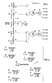
- FIG 1 illustrates a sonde arrangement 10 according to the invention.
- Simple individual arrays are preferred generally consisting of a single transmitter coil and two receiver coils 16, 14 (16', 14').
- the basic three-coil array includes a primary receiver coil 16 located at a distance L from the transmitter.
- a secondary or bucking coil 14 acts as a mutual inductance balancing soil.
- the secondary coil is connected in series with the primary coil, but is wound in an opposite sense to the primary coil.
- the placement of the secondary coil between the transmitter coil 12 and the primary receiver coil 16 is a matter of choice, but once its placement is fixed, the number of its windings may be selected so as substantially to balance or null the direct mutual coupling between the transmitter and the receiver array. If the position of the secondary coil is selected to be L/2, or half-way between the transmitter coil 12 and the receiver coil 16, it requires one-eighth as many turns as for the primary receiver coil 16.
- the multi-channel sonde 10 is constructed of a number of these simple arrays by placing a single transmitter 12 at the center of the tool and placing pairs of receiver coils such as pairs 16,14 and 16',14' on either side of it.
- Amplifiers 20, 20' and phase-sensitive detectors 22, 22' may be constructed of conventional analog induction electronics but preferably digital PSD are used as will be discussed below with regard to a particular preferred embodiment.
- a multi-frequency oscillator 26, operating at frequencies of 20 and 40, kHz excite transmitter 12.
- the receiver arrays spaced, for example, three feet from transmitter 12, respond with voltage signals, v i , v i ' which depend on formation characteristics.
- Such voltage signals are amplified and resolved into in-phase (R) and out-of-phase or quadrature (X) components at the two excitation frequencies 20 and 40 kHz.
- R in-phase
- X out-of-phase or quadrature
- Figure 2 illustrates schematically a four receiver array sonde 10' including receiver arrays placed at three feet on both sides of the transmitter. Receiver arrays are also provided having their main receiver coils spaced at five feet on both sides of the transmitter. Many other receiver arrays may be placed above and/or below transmitter coil 26, depending on the preferred design of the induction equipment.
- Oscillators 26 may, for example, include current signals of 20, 40, 80 and 160 or 25, 50,100 and 200 kHz. Certain frequencies may be used with certain receiver arrays. For example, the five foot receivers of Figure 2 may be sensed at 20 and 40 kHz while the three foot receivers may be sensed at 20 and 160 kHz, etc.
- the invention involves a multi-channel sonde having a plurality of arrays (not necessarily balanced and symmetrical as shown in Figures 1 and 2) with different spatial responses (e.g., the arrays are of different lengths from the transmitter coil) and uses deconvolution to combine the output of these arrays in digital processing under software control at a surface instrumentation system.
- Deconvolution is used here as defined by Doll to mean that the output measurement (for example, conductivity or resistivity) at a particular depth is computed from a weighted combination of the sonde response at the measure depth and adjacent depths.
- Multi-channel deconvolution is a generalization of this induction deconvolution in that data from a number of depth points from several arrays are weighted and summed to determine the output measurement at a given depth.
- the response function g(p,z) is independent of the formation and can be calculated using Maxwell's equations in free space. The result is simply the well known Doll geometrical factor. Filters described immediately below are based on linear theory.
- the p integration may be done to obtain:
- the z integration may be performed to obtain:
- g(p,z) the geometrical factor of the tool
- g(p) and g(z) are called radial and vertical geometrical factor respectively.
- the shape of the geometrical factor depends upon the placement and winding of the transmitter and receiver coils.
- a multi-channel tool may be constructed of a number of simple arrays by placing a single transmitter at the center of the tool and placing pairs of receiver coils on one or the opposite side of it or on both sides of it.
- Figure 2 illustrates the configuration for example of a possible four channel "balanced" sonde.
- the main coil spacings are three and five feet with receiver coils located above and below the transmitter.
- the response function for the sonde with the receiver coils below the transmitter is simply the reversal of the response function for the sonde with the receiver coils above the transmitter. That is:
- the radial geometrical factors of the two sondes is the same, and so having them both does not provide any additional radial information. There is, however, additional vertical and two-dimensional information. There is also the additional benefit of ease in making the response function symmetric, and possibly a benefit in improving borehole effect.
- Deconvolution filters may be designed which are optimal in the sense that the response minimizes some error norm when compared with the desired response.
- the vertical response g(z) should be sharp to allow the determination of resistivity of a thin bed and should be symmetric.
- the tails of the response should die off quickly away from the peak.
- a smooth response without overshoot may be desired although some log analysts seem to prefer a sharper response with overshoot.
- the Radial response g(p) should be well localized to a known range of radial values. Often this means that the radial response should be small inside of or outside of a given radius.
- the response of the tool should not be overly sensitive to caves or to very high conductivity invaded regions, when the total integrated radial response is not sensitive to this region.
- the deconvolution process should not introduce excessive unwanted noise into the log.
- the basic equation of multi-channel deconvolution is: where the subscript n refers to the channel number and ⁇ n (z) is the conductivity measured by the nth array at position z. The summation goes from channel 1 to channel N and from zn m in to Znmax , the minimum and maximum depth for each channel. The a's are the filter coefficients which are to be determined.
- the vertical and radial geometrical factors can also be written in terms of the filter weights and the vertical and radial geometrical factors of the individual arrays,
- Equations 9, 10, and 11 produce the various response functions from the individual response functions and the filter weights.
- the desired characteristics of the system must be expressed in terms of g(p,z), g(z), or g(p).
- the relative importance of each of the desired characteristics must also be set which in turn will determine how the trade-off between the conflicting criteria occur.
- G is a m x n matrix composed of response functions
- a is a n x 1 column vector of filter weights
- d is an m x 1 column vector of desired characteristics.
- n unknowns corresponding to n filter weights.
- the column vector a is all the separate filter weights in order
- Each row of G and the corresponding value of d correspond to one of the Equations 9-11.
- the vertical geometrical factor might be desired to look like a gaussian with some width In matrix notation this would correspond to If there were only a single channel to deconvolve, this would reduce to the normal formula for deconvolution, and the matrix G would have a Toeplitz form. That is Instead of a target function for the vertical geometrical factor, a target function for the radial geometrical factor may be desired. For instance, the radial geometrical factor could be specified to be zero for some range of radius, e.g., This would result in a matrix equation of the form
- An example of a two-dimensional condition might be to specify the response to be zero at radii of 4, 8, and 12 inches. Such a set of conditions contributes to controlling the tool's cave effect.
- Equation (12) the form of Equation (12) is still applicable.
- G and d will be the vertical catenation of the corresponding matricies presented in Equations 15, 18 and 19.
- Equation (12) can not be solved exactly, Instead a combination of filter weights is to be found which minimizes some norm of the error between the actual response achieved and the desired response.
- Minimizing the Euclidian norm in Equation 9 corresponds to finding the least squares solution to the equation.
- Minimizing the Chebychev norm corresponds to finding the solution which minimizes the maximum error between the actual and the desired solution.
- Equation 11 shows that the radial geometrical factor of a multi-channel sonde can be expressed as a sum of the raidal geometrical factors of the individual arrays. If the summation is performed over depth this dependence can be written more explicitly as where
- a number of radial functions may be combined to achieve certain radial criteria. These criteria consist of the following types of conditions for the example radial focusing:
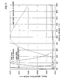
- Figures 3 through 6 show the results of this focusing process.
- the radial response of five three-coil, mutually balanced sondes with main coil spacings of 1, 2, 3, 5 and 8 feet have been combined.
- Figure 3 shows the five basis functions. They are identical except for scaling. Each is normalized to unit area.
- Figures 4 through 6 show the best linear combination of the basis functions in order to make the radial response function zero out to some limit. This limit varies from 6 to 48 inches.
- the "best" combination is defined in either a least squares sense or a Chebychev sense.
- the Chebychev norm is equivalent to minimizing the maximum deviation between the actual and the desired responses.
- the minimax solution always reaches equal deviations from the desired solution at a multiple of points, and that these maxima appear to be larger than the least squares solution. This multiple equal maxima deviation is a property of this norm.
- the apparent excess of the minimax norm is not true. In every case the least squares solution reaches a higher value at the boundary of the region where it is desired to achieve a value of zero.
- Figure 7 shows three responses which are formed from the basis functions associated with array lengths of 0.5, 1, 2, 4, and 8 feet. In these cases, it is attempted to achieve responses which are nonzero only inside of six inches, only outside of 24 inches, and only between 6 and 24 inches. For this display, the curves are normalized to the same maximum vertical height.
- the software combination of these elemental sondes achieves far more separation of radial response that the currently available commercial tools.
- the responses are almost orthogonal, that is, they have little signal coming from the same radial part of the formation. This makes it far easier to interpret the invasion of the borehole.
- a true conductivity profile can be produced by combining the separate sub-sondes in software to concentrate the response from a particular part of the formation.
- the response of an array depends not only upon its coil configuration but also upon the skin depth of the formation.
- This skin depth is dependent upon the product of the formation conductivity and the frequency of operation of the induction sonde. Since the frequency may be specified, and since the skin depth is very often an important length scale in the problem and is often the dominant one, the skin effect can be used to advantage in producing a localized measurement of conductivity.
- very simple sondes are used, e.g., a symmetrical sonde with a single transmitter and a pair of two-coil receiver arrays. Multiple channels of information are obtained by acquiring both in-phase and quadrature components of each array signal at several frequencies.
- the simple sonde described above operating at 20,40,100, and 200 kHz provides 16 channels, each with a different associated spatial response.
- the inversion of this data requires an accurate model for the response functions of the arrays as a function of coil placement, conductivity and frequency.
- the Born approximation to the array response which is the first term in an expansion of the response in powers of deviations in the conductivity from some average background conductivity provides the model.
- gb (p,z : a) is the Born response function or the Born kernal.
- the Born kernal is now complex.
- aa R (z) K RV R (z)
- O ax(z) K XA vx(z) based upon the normal resistive or upon the reactive signal.
- the geometrical factor theory can be viewed as a special case of the more general Born approximation where the average conductivity is chosen to be zero.
- Multi-channel deconvolution now looks just like the above analysis for low conductivity formations except for the inclusion of both R and X signals.
- the index n now runs over all arrays and also over R and X signals.
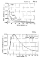
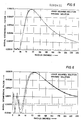
- the simple symmetric sonde shown in Figure 1 may be considered. Each main coil spacing is 3 feet, making a total sonde length of 6 feet. Frequencies of operation are 20 and 40 kHz, yielding 8 channels (2 frequencies, in-phase and quadrature signal components, 2 arrays). The resulting response functions are shown in Figures 8 and 9. The vertical resolution is 5.5 inches and depth of investigation is 73 inches. There is virtually no response within a radius of 10 inches.
- a computed log of a layered formation ( Figure 10) shows this sonde capable of resolving a 1-ft high conductivity (low resistivity) bed. The technique works because the signals at 20 and 40 kHz for each array are weighted nearly equally and opposite in sign in the deconvolution filter.
- the total response is small near the borehole where skin-effect is small and is nearly frequency-independent, and numerically significant further into the formation where skin-effect results in a difference between the responses at the two frequencies.
- Small frequency differences result in large depths of investigation; as the frequency difference is made larger, the radial response of the sonde moves in toward the borehole axis.
- Very thin invaded beds represent a very difficult class of two-dimensional heterogeneities that often degrade the apparent resolution of a sonde as seen on a log. Additional formation information may be obtained by a sonde design using both multiple array spacings and multiple frequencies.
- Figure 11 illustrates the log obtained from such a sonde with array spacings of 1, 2, and 3 feet. The one foot array pair operates at 20 and 160 kHz, the two foot sonde at 20 and 80 kHz, and the three foot array pair at 20 and 40 kHz. The one foot thick bed with a radius of invasion of 10 inches is well resolved.
- the response of a transmitter-receiver coil array is dependent on its transmitter frequency due to skin effect of the induced loop of current in the formation.
- the loop current tends to flow in a radial band closer to the borehole.
- the induced loop current in the formation tends not to be so much influenced by skin effect and current flows in a radial based relatively further from the borehole than when a higher frequency is used.
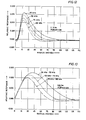
- Figure 12 illustrates the effect of frequency on radial depth of investigation.
- Figure 12 shows relative response functions for a single three coil, three foot array in a formation of 2 S/M conductivity.
- the three coil, three foot array is one with a single transmitter with a two coil receiver array, where the receiver array has a primary coil receiver spaced three feet away from the transmitter and having a secondary receiver coil disposed between the primary receiver coil and the transmitter coil and is wound in the opposite direction from that of the primary receiver coil.
- the secondary receiver coil is in electrical series with the primary receiver coil and the mutual coupling signal induced in the secondary receiver coil tends to balance the mutual coupling signal induced in the primary receiver coil.
- Figure 13 shows the relative response of the difference between several responses of Figure 12. Specifically three different response functions are shown: the first is the difference between the 25 kHz response and the 50 kHz response; the second is the difference between the 50 kHz response and the 75 kHz response; the third is the difference between the 75 kHz response and the 100 kHz response.
- the first difference curve has the deepest depth of investigation, the second difference curve has not so deep a depth of investigation as the first, and the third difference curve has a more shallow depth of investigation than the other two curves. Consequently, as shown above, operating a single induction coil array at multiple frequencies and taking the difference between responses at different frequencies provides a way advantageously to use "skin effect" to obtain a radial profile of the formation.
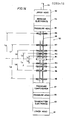
- FIGs 14 and 15 illustrate respectively the preferred downhole sonde and system of the invention.
- the sonde 50 includes a transmitter and receiver coil array having a single transmitter coil T and nine receiver arrays R1-R9. Each receiver array includes a pair of coils including a primary receiver coil and a secondary receiver coil placed between the primary receiver coil and the transmitter coil.
- receiver coil R1 of sonde 50 includes a primary coil spaced a distance Li from transmitter coil T.
- the receiver coil array also includes, as indicated above, a series connected, oppositely would secondary receiver coil spaced between the transmitter coil and the primary receiver coil and has a number of turns on it to substantially eliminate or balance the mutual signal induced by mutual coupling between the transmitter and the receiver array.
- the coil array of the sonde 50 uniquely includes an interweaving pattern, such that the receiver coil array having the next largest spacing from receiver array Ri is placed below the transmitter coil T a distance L 2 which is greater in absolute terms than the distance Li.
- receiver array R 3 is placed above array R 1 at a distance L 3 from transmitter coil T.
- the distance Ls is greater absolutely than is the distance L 2 .
- Receiver coils R 4 , Rs, Rs, R 7 , R 8 and R g are placed above and below the transmitter coil T in the same pattern. That is, L 4 > ; Ls; L 5 >; L 4 ; Ls >; Ls; L 7 >; Ls; L 8 >; L 7 ; and L 9 >; L 8 .
- the transmitter and receiver coils are preferably disposed on a metallic support 69 according to the construction described in U.S. patent 4,651,101, assigned to the assignee of this application. Such patent is incorporated herein.
- the coil array and electrical leads or conductors connecting them to receiver electronics section 64 or transmitter electronics 63 are subject to the drilling fluid pressure of the well.
- the receiver electronics 64 and transmitter electronics 63 are mechanically isolated from the drilling fluid pressure.
- Pressure heads 66 and 65 and pressure compensator 67 provide electrical conductor paths protected from pressure between the electronics sections 64 and 63 and the transmitter and receiver coils.
- Lower head 61 serves as a connector to other logging tools to be placed below sonde 50 or as an end cap for the sonde 50.
- Upper head 62 serves as a connector to other logging tools which may be connected to sonde 50 or to the logging cable 54.
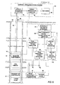
- FIG 15 is a schematic illustration of the sonde 50 of Figure 14 suspended in a borehole 52 by a multiconductor wireline cable 54.
- the sonde 50 communicates with a surface instrumentation system 80 which includes an uphole telemetry system 82, a signal processing computer 84 and an output device such as recorder 86.
- a winch and a depth signal encoder 88 are provided for transporting the sonde 50 in the borehole and providing depth information to computer 84.
- the transmitter electronics include a master clock 90 and a four frequency transmitter 91.
- the output of transmitter 91 drives transmitter coil T at four separate frequencies, preferably at about 25 kHz, 50 kHz, 100 kHz and 200 kHz.
- the receiver electronics preferably includes a dual frequency amplifier associated with a particular receiver coil array R i .... Rg.
- Amplifier 101 is associated with receiver R 1 ; ...
- Amplifier 109 is associated with receiver Rs.
- each amplifier is tuned so as to be responsive to at least two frequencies of the transmitter 91.
- the preferred frequency tuning for each of the amplifiers 101-109 is presented in Table I.
- each amplifier 101....109 is applied to an individual analog to digital (A/D) converter 111....119.
- A/D analog to digital
- the digital output of each A/D converter is applied to a digital multiple frequency phase sensitive detector 120 where the in-phase signal (R) and quadrature signal (X) of each receiver at each of the frequencies specified in Table I is detected.
- the output of A/D converter 115 responsive to the receiver R s , is resolved into four digital signals representing the received voltaae v:
- the signal at each of the receivers is resolved into separate signals at two frequencies, each further being resolved into its in-phase (R) component and out-of-phase (X) component. Consequently, at each three inch depth increment for each receiver, four signals are captured.
- Such signals are applied to downhole telemetry interface circuit 121 and transmitted for storage in Surface Instrumentation System 80 computer 84 via cable 54 and uphole telemetry interface 82.
- Such signals are depth tagged by means of encoder 88 which provides a simultaneous depth signal to computer 14.
- Such depth tagged signals are stored in computer 84 for deconvolution processing according to a filter weighted sum of all the signals stored during the logging run.
- Such filter weights are preferably predetermined generally according to the techniques described above in the section labeled "multi-channel deconvolution filter assuming no skin effect” and in particular the section labeled "multi-channel deconvolution filter assuming pressure of skin effect”.
- One set of preferred filter weights for the preferred sonde of Figure 12 is shown in Table II below. Such weights apply for the transmitter-primary receiver coil spacings shown below in Table III.
- a log of conductivity versus depth may be produced from the conductivity determination at each depth on recorder 86.
- the tool illustrated in Figure 14 may be placed in a measurement sub in a drilling string for measurement-while-drilling (MWD) applications.
- Communication with surface instrumentation may be by means other than a logging cable.
- a pulse monitoring system known in the MWD art may be used. For this reason, these changes are desired to be included in the appended claims.
- the appended claims recite the only limitation to the present invention and the descriptive manner which is employed for setting forth the embodiments and is to be interpreted as illustrative and not limitative.
Abstract
Description
- This invention generally relates to a method and apparatus for investigating earth formations traversed by a borehole, and more particularly, pertains to a new and improved method and apparatus for electromagnetic well logging. Still more particularly this invention relates to a new and improved method and apparatus for acquiring multiple signals during induction logging, combining these signals in software, and creating a depth tagged representation of resistivity or conductivity from a weighted sum of signals from that depth or from that depth and neighboring depths.
- Generally, speaking, in electromagnetic well logging, commonly referred to as "induction logging," a transmitter coil energized by alternating current is lowered into a well or borehole and indications are obtained of the influenced of surrounding formulations on the electromagnetic field established by the coil. Usually such indications are obtained by observing the voltage induced in a receiver coil lowered into the borehole in coaxial relationship with the transmitter coil and axially spaced apart therefrom.
- Commonly available induction logging tools include a transmitter array and a receiver array each consisting of a set of coils connected together in series. Such a transmitter/receiver array is illustrated in U.S. patent 3,067,383 issued December 4, 1962 to Dennis R. Tanguy. The transmitter is driven by a constant amplitude current at 20 kHz. The induction measurement consists of recording the total voltage induced in the receiver array.
- Such commonly available commercial logging tools in service today record only the component of the total voltage which is 180 degrees out of phase (caIIed the "in phase" or "real voltage, R") with the transmitter current. Such an induction sonde is sensitive to a spatial average of the conductivity of the surrounding formation. The average function is determined by the placement and winding of the transmitter and receiver coils.
- Logging methods and apparatus are described in U.S. patent 4,513,376 issued April 23, 1985 to Thomas Barber where not only is determined the real "R" or in-phase of the receiver voltage component, but also the quadrature or 90° out-of-phase "X" component of the receiver voltage. The R and X components are used to estimate formation resistivity.
- Only minimum processing of the receiver data is currently used with commercially available tools to enhance receiver voltage signals. Tools designed for medium radial measurement of conductivity use a single point by point boost method to account for skin-effect in the formation. Such a "boosting" of the receiver signal is described in U.S. patent 3,226,633 issued December 28, 1965 to W.P. Schneider.
- Tools designed for deep radial measurement of conductivity use a three depth deconvolution process followed by a skin effect boost. Such a deconvolution process is described in U.S. patent 3,166,709 issued January 19, 1965 to Henri-Georges Doll. The purpose of the three point deconvolution is to reduce the tool response sensitivity to high conductivity shoulders which are far away.
- Another approach to induction logging is described in a paper by D.W. Martin presented to an SPWLA Symposium in 1984 entitled, "The Digital Induction - A New Approach to Improving the Response of the Induction Measurement". Martin describes a "Digital Induction Sonde" which includes four receiver coils spaced vertically above a transmitter coil on a sonde mandrel. The signal induced in each of the four receiver coils is amplified, digitized and transmitted direct to the surface for computer processing before the resistivity is determined for the borehole log.
- All the "raw data" from the receiver coils is recorded and stored for computer processing. Specifically, the depth of investigation can, during post job processing be varied continuously, thereby allowing an invasion profile to be produced.
- It is generally an object of the invention to provide an improved induction method and apparatus having advantages and features superior to the induction logging methods and systems of the prior art.
- It is an object of the invention to provide a new and improved induction sonde arrangement for induction logging.
- It is another object of the invention to provide multiple receiver arrays having different array lengths for surface multi-channel deconvolution processing at a measure depth and adjacent depths.
- It is another object of the invention to provide induction logging apparatus in which multiple frequencies are used to excite the transmitter, thereby inducing multiple receiver signals, each with a different associated spatial response.
- It is another object of the invention to provide an induction logging system with multiple frequency excitation in which both in-phase and quadrature components of each receiver signal are acquired.
- It is another object of the invention to provide an accurate model for the response functions of the arrays as a function of coil replacement, conductivity and frequency.
- The objects identified above as well as other advantages and features of the invention are incorporated in a new and improved multi-channel induction sonde having a single transmitter coil and at least one receiver coil array. A source of electrical energy is coupled to the transmitter coil. The electrical energy source includes at least two distinct oscillating signals, the frequency of each signal being substantially constant. Electrical receivers including an amplifier, A/D converter and multi-frequency phase sensitive detector are coupled to the receiver arrays for producing receiver signals at the frequencies of the oscillator source. A surface instrumentation unit digital processor combines the signals and produces an output signal representative of a characteristic of the formation.
- In a preferred embodiment of the invention, a plurality of receiver arrays, R1, R2, Rs, etc. are coaxially mounted with the transmitter coil. Each of the receiver coils has a primary receiver coil disposed at increasing longitudinal distances, Li, L2, L3, etc., from the transmitter coil. The odd numbered receiver arrays, R1, R3, R5, etc., are mounted on one longitudinal side of the transmitter coil, and the even numbered receiver arrays, R2, R4, Rs, etc., are mounted on the opposite longitudinal side of the transmitter coil. Electrical receivers produce an in-phase (R) signal and an out-of-phase (X) signal for each array at each of the frequencies of the source of electrical energy. Such signals are stored for each of the measurement locations in the borehole as the induction sonde is transported through it. For each measurement location, such stored signals are combined by using a predetermined weighting matrix to produce a signal representative of the conductivity or resistivity of the formation at that measurement location. Such signals are recorded as a function of measurement depth to produce a log of the characteristic.
- A method for obtaining a radial profile at a measurement location is also provided whereby a transmitter coil is driven with at least two oscillating currents of different frequencies. A first signal from a receiver coil at frequency f1 and a second signal f2 from such receiver coil are obtained and a difference signal between such signals is produced. The difference signal is representative of a characteristic of the formation at a greater radial depth than the first signal or the second signal.
- The objects, advantages and features of the invention will become more apparent by reference to the drawings which are appended hereto and wherein like numerals indicate like parts and wherein an illustrative embodiment of the invention is shown, of which:
- Figure 1 illustrates a balanced symmetrical induction logging sonde with a single transmitter and a pair of two coil receiver arrays, where the transmitter is excited with simultaneous multiple frequencies and the received induced voltages at individual frequencies are separated into in-phase and quadrature components;
- Figure 2 illustrates a balanced four receiver induction design.
- Figure 3 illustrates individual radial response functions for three coil induction arrays with main coil spacings of 1, 2, 3, and 8 feet;
- Figures 4-6 illustrate composite radial response functions of the outputs of three coil arrays with coil spacings, 1, 2, 3, 5 and 8 feet, optimally weighted to produce respectively a zero output inside 6 inches (Figure 4), inside 24 inches (Figure 5) and inside 48 inches (Figure 6) ;
- Figure 7 illustrates composite radial response functions of the outputs of three coil arrays with coil spacings of .5, 1, 2, 4 and 8 feet optimally weighted to produce combined radial geometrical factors which are non-zero inside six inches, non-zero from six to twenty-four inches, and zero within twenty four inches (equivalently, non-zero outside 24 inches);
- Figures 8 and 9 illustrate respectively the composite vertical response function and radial response function of a symmetrical balanced sonde with three foot arrays operating at multiple frequencies;
- Figure 10 illustrates a computed log of the logging apparatus according to the invention having vertical and radial characteristics of Figure 8 and 9 showing resolution of a high conductivity one foot bed;
- Figure 11 illustrates a computed log from a sonde with
array spacings - Figure 12 illustrates the frequency dependence of a radial response function;
- Figure 13 illustrates the frequency dependence of differences of radial response functions;
- Figure 14 illustrates a preferred embodiment of a logging sonde according to the invention; and
- Figure 15 schematically illustrates a system for multi-channel processing with multiple receivers showing down hole components for producing signals at each measurement location corresponding to the in-phase (R) and out-of-phase (X) components at each array for each driving frequency.
- Figure 1 illustrates a
sonde arrangement 10 according to the invention. Simple individual arrays are preferred generally consisting of a single transmitter coil and tworeceiver coils 16, 14 (16', 14'). The basic three-coil array includes aprimary receiver coil 16 located at a distance L from the transmitter. A secondary or buckingcoil 14 acts as a mutual inductance balancing soil. The secondary coil is connected in series with the primary coil, but is wound in an opposite sense to the primary coil. The placement of the secondary coil between thetransmitter coil 12 and theprimary receiver coil 16 is a matter of choice, but once its placement is fixed, the number of its windings may be selected so as substantially to balance or null the direct mutual coupling between the transmitter and the receiver array. If the position of the secondary coil is selected to be L/2, or half-way between thetransmitter coil 12 and thereceiver coil 16, it requires one-eighth as many turns as for theprimary receiver coil 16. - Preferably the
multi-channel sonde 10 is constructed of a number of these simple arrays by placing asingle transmitter 12 at the center of the tool and placing pairs of receiver coils such aspairs Amplifiers 20, 20' and phase-sensitive detectors 22, 22' (PSD) may be constructed of conventional analog induction electronics but preferably digital PSD are used as will be discussed below with regard to a particular preferred embodiment. As illustrated, amulti-frequency oscillator 26, operating at frequencies of 20 and 40, kHz excitetransmitter 12. The receiver arrays, spaced, for example, three feet fromtransmitter 12, respond with voltage signals, vi, vi' which depend on formation characteristics. Such voltage signals are amplified and resolved into in-phase (R) and out-of-phase or quadrature (X) components at the twoexcitation frequencies - Figure 2 illustrates schematically a four receiver array sonde 10' including receiver arrays placed at three feet on both sides of the transmitter. Receiver arrays are also provided having their main receiver coils spaced at five feet on both sides of the transmitter. Many other receiver arrays may be placed above and/or below
transmitter coil 26, depending on the preferred design of the induction equipment. - As the description of the deconvolution processors will show below, more information channels allow more precise determination of formation characteristics, but adding more and more receiver arrays ultimately undesirably lengthens the sonde, making it more difficult to use practically in field operations. It should also be mentioned here that more than two frequencies may be used with the logging system.
Oscillators 26 may, for example, include current signals of 20, 40, 80 and 160 or 25, 50,100 and 200 kHz. Certain frequencies may be used with certain receiver arrays. For example, the five foot receivers of Figure 2 may be sensed at 20 and 40 kHz while the three foot receivers may be sensed at 20 and 160 kHz, etc. - At the heart of the invention is a method and apparatus for deconvolving or "weighting" in a summation the various received signal channels or sondes such as illustrated in Figures 1 and 2. The invention involves a multi-channel sonde having a plurality of arrays (not necessarily balanced and symmetrical as shown in Figures 1 and 2) with different spatial responses (e.g., the arrays are of different lengths from the transmitter coil) and uses deconvolution to combine the output of these arrays in digital processing under software control at a surface instrumentation system.
- Deconvolution is used here as defined by Doll to mean that the output measurement (for example, conductivity or resistivity) at a particular depth is computed from a weighted combination of the sonde response at the measure depth and adjacent depths. Multi-channel deconvolution is a generalization of this induction deconvolution in that data from a number of depth points from several arrays are weighted and summed to determine the output measurement at a given depth.
- The description below describes the design of a multi-channel deconvolution filter assuming that there is no skin effect. The technique is then extended to include skin effect.
- When the formation conductivity is low, the currents in the formation are small; consequently the fields in the formation are not significantly different from those which would exist in a vacuum. In other words, skin effect is small and may be ignored. In that case, each of the n arrays produces a spatial average of the formation conductivity

- an = conductivity as measured by the nth channel in the array,
- p radial distance from the center line of the borehole,
- z' = distance from the measure point z of the sonde,
- a (p,z') = the conductivity pattern of the formations adjacent the borehole,
- gn (p,z') = the response function of the nth channel in the array.
- The response function g(p,z) is independent of the formation and can be calculated using Maxwell's equations in free space. The result is simply the well known Doll geometrical factor. Filters described immediately below are based on linear theory.
- For formations which have no radial variation, the p integration may be done to obtain:


- The relationship is known as g(p,z), the geometrical factor of the tool, and g(p) and g(z) are called radial and vertical geometrical factor respectively. The shape of the geometrical factor depends upon the placement and winding of the transmitter and receiver coils.
- As described above, a multi-channel tool may be constructed of a number of simple arrays by placing a single transmitter at the center of the tool and placing pairs of receiver coils on one or the opposite side of it or on both sides of it. Figure 2 illustrates the configuration for example of a possible four channel "balanced" sonde. The main coil spacings are three and five feet with receiver coils located above and below the transmitter. The response function for the sonde with the receiver coils below the transmitter is simply the reversal of the response function for the sonde with the receiver coils above the transmitter. That is:

- The radial geometrical factors of the two sondes is the same, and so having them both does not provide any additional radial information. There is, however, additional vertical and two-dimensional information. There is also the additional benefit of ease in making the response function symmetric, and possibly a benefit in improving borehole effect.
- Deconvolution filters may be designed which are optimal in the sense that the response minimizes some error norm when compared with the desired response.
- Additionally there are desirable characteristics of the response of an induction tool. Often these characteristics are contradictory. Some of the most common of the characteristics are:
- The vertical response g(z) should be sharp to allow the determination of resistivity of a thin bed and should be symmetric. The tails of the response should die off quickly away from the peak. A smooth response without overshoot may be desired although some log analysts seem to prefer a sharper response with overshoot.
- The Radial response g(p) should be well localized to a known range of radial values. Often this means that the radial response should be small inside of or outside of a given radius.
- The response of the tool should not be overly sensitive to caves or to very high conductivity invaded regions, when the total integrated radial response is not sensitive to this region.
- The deconvolution process should not introduce excessive unwanted noise into the log.
- It is impossible to achieve all of these characteristics simultaneously, and one of the primary advantages of this invention is that the trade-off between the various properties of the response may be varied and hence studied systematically. The basic equation of multi-channel deconvolution is:

channel 1 to channel N and from znmin to Znmax, the minimum and maximum depth for each channel. The a's are the filter coefficients which are to be determined. - This equation implies that the signal from a set of N arrays will be obtained at a number of positions and will be weighted and added to obtain a log value. The values of the filter coefficients (a's) as well as the choice of independent arrays will determine the tool response. If each of the arrays has a response which can be written in the form of
Equation 1, then the total response of the multi-channel sonde can be written in the same general form,

- The vertical and radial geometrical factors can also be written in terms of the filter weights and the vertical and radial geometrical factors of the individual arrays,


- The two-dimensional geometrical factor, need not be considered, but rather only the vertical and radial geometrical factors of the individual subsondes.
Equations - These equations can be written more compactly in matrix form

a n x 1 column vector of filter weights, and d is anm x 1 column vector of desired characteristics. There are m equations (corresponding to m desired characteristics), in n unknowns (corresponding to n filter weights). In general, there will be more equations than unknowns, and it will not be possible to solve them exactly but the vector a will have to be determined to minimize some error. The column vector a is all the separate filter weights in order


- All the columns of G corresponding to a single array are identical. This is due to the fact that the radial geometrical factor is calculated by integrating the two-dimensional geometrical factor over z.
- Certain aspects of the induction tool behaviour are due to the two-dimensional response. Certain characteristics of the two-dimensional response may be specified. This leads to a matrix equation similar to
Equation 15.
- An example of a two-dimensional condition might be to specify the response to be zero at radii of 4, 8, and 12 inches. Such a set of conditions contributes to controlling the tool's cave effect.
- Where characteristics of the vertical, radial and two-dimensional geometrical favors are to be specified simultaneously, then the form of Equation (12) is still applicable. In this case, G and d will be the vertical catenation of the corresponding matricies presented in
Equations - In general there are more design criteria than there are unknown filter weights. Consequently Equation (12) can not be solved exactly, Instead a combination of filter weights is to be found which minimizes some norm of the error between the actual response achieved and the desired response.
- Typical norms are often written in the form:

Equation 9 corresponds to finding the least squares solution to the equation. Minimizing the Chebychev norm corresponds to finding the solution which minimizes the maximum error between the actual and the desired solution. - In a real situation, it is important to achieve all of the design criteria by equal amounts. This problem is handled by weighting the rows in G and d of
Equation 9 by various amounts. This results in a larger contribution to the error norm (be it Euclidian or Chebychev) from those equations corresponding to conditions which are more important to approximate well and a smaller contribution from those equations corresponding to conditions which are less important. It is always necessary to make such a decision of priorities. The weight does not correspond precisely with a subjective decision on relative importance, since the magnitudes of the elements of Ga may differ greatly. In particular, the g(p,z) has the dimension of 1/(length**2) while g(p) and g(z) have the dimension of 1/length. Thus the choice of the length scale will alter the relative importance of these equations without fundamentally changing the problem. - Equation 11 shows that the radial geometrical factor of a multi-channel sonde can be expressed as a sum of the raidal geometrical factors of the individual arrays. If the summation is performed over depth this dependence can be written more explicitly as


- A number of radial functions may be combined to achieve certain radial criteria. These criteria consist of the following types of conditions for the example radial focusing:
- 1. Set the radial geometrical factor to a certain value for a range of r.
- 2. Normalize the radial geometrical factor to one.
- 3. Zero the mutual induction of the array. If the sonde is built up of sondes which are not mutually balanced, then the sum Ei /L"3 must be zero, where Ln is the effective length of each of the sub-arrays.
- Figures 3 through 6 show the results of this focusing process. In each case, the radial response of five three-coil, mutually balanced sondes with main coil spacings of 1, 2, 3, 5 and 8 feet have been combined. Each sonde includes a one turn transmitter located at z = and two receivers located at L and L/2. Figure 3 shows the five basis functions. They are identical except for scaling. Each is normalized to unit area. Figures 4 through 6 show the best linear combination of the basis functions in order to make the radial response function zero out to some limit. This limit varies from 6 to 48 inches. For each attempt, the "best" combination is defined in either a least squares sense or a Chebychev sense.
- The Chebychev norm is equivalent to minimizing the maximum deviation between the actual and the desired responses. The minimax solution always reaches equal deviations from the desired solution at a multiple of points, and that these maxima appear to be larger than the least squares solution. This multiple equal maxima deviation is a property of this norm. The apparent excess of the minimax norm is not true. In every case the least squares solution reaches a higher value at the boundary of the region where it is desired to achieve a value of zero.
- Figure 7 shows three responses which are formed from the basis functions associated with array lengths of 0.5, 1, 2, 4, and 8 feet. In these cases, it is attempted to achieve responses which are nonzero only inside of six inches, only outside of 24 inches, and only between 6 and 24 inches. For this display, the curves are normalized to the same maximum vertical height. The software combination of these elemental sondes achieves far more separation of radial response that the currently available commercial tools. In addition, the responses are almost orthogonal, that is, they have little signal coming from the same radial part of the formation. This makes it far easier to interpret the invasion of the borehole. Using this method, a true conductivity profile can be produced by combining the separate sub-sondes in software to concentrate the response from a particular part of the formation.
- These curves are achieved by combining radial response functions only. In a real tool it is important to achieve a balance between the radial performance and the other aspects of sonde response. In particular, the achievement of a very deep response requires a larger weighting on the longer arrays, while a shallow response requires a larger weighting on the shorter ones. Good vertical resolution is, of course, much easier with short sondes than with long ones. Thus there is the unavoidable problem of conflicting criteria. That is, it is difficult to achieve a good depth of investigation with a sonde which also has good vertical resolution. This means that the possibilities of obtaining a radial profile will be greatest for thick beds where there need not be as much concern with a sharp vertical response.
- In high-conductivity formations, the response of an array depends not only upon its coil configuration but also upon the skin depth of the formation. This skin depth is dependent upon the product of the formation conductivity and the frequency of operation of the induction sonde. Since the frequency may be specified, and since the skin depth is very often an important length scale in the problem and is often the dominant one, the skin effect can be used to advantage in producing a localized measurement of conductivity.
- As above, very simple sondes are used, e.g., a symmetrical sonde with a single transmitter and a pair of two-coil receiver arrays. Multiple channels of information are obtained by acquiring both in-phase and quadrature components of each array signal at several frequencies. The simple sonde described above operating at 20,40,100, and 200 kHz provides 16 channels, each with a different associated spatial response. The inversion of this data requires an accurate model for the response functions of the arrays as a function of coil placement, conductivity and frequency. The Born approximation to the array response, which is the first term in an expansion of the response in powers of deviations in the conductivity from some average background conductivity provides the model.
- The use of the Born approximation starts from a slightly different point of view than the deconvolution filter described above assuming low conductivity formations. If the formation may reasonably be determined to have an "average" or "background" conductivity σ, then it can be determined as to how the received voltage varies with changes in the formation conductivity.
- This can be written in a form similar to the geometrical factor

- Here gb (p,z : a) is the Born response function or the Born kernal. The Born kernal is now complex. Following as above, two apparent conductivities are defined as aaR(z) = KRV R(z) and Oax(z) = KXA vx(z) based upon the normal resistive or upon the reactive signal. Thus these signals are now put on the same footing. The geometrical factor theory can be viewed as a special case of the more general Born approximation where the average conductivity is chosen to be zero.
- Multi-channel deconvolution now looks just like the above analysis for low conductivity formations except for the inclusion of both R and X signals.

- The index n now runs over all arrays and also over R and X signals.
- As an example of the use of multiple frequencies, the simple symmetric sonde shown in Figure 1 may be considered. Each main coil spacing is 3 feet, making a total sonde length of 6 feet. Frequencies of operation are 20 and 40 kHz, yielding 8 channels (2 frequencies, in-phase and quadrature signal components, 2 arrays). The resulting response functions are shown in Figures 8 and 9. The vertical resolution is 5.5 inches and depth of investigation is 73 inches. There is virtually no response within a radius of 10 inches. A computed log of a layered formation (Figure 10) shows this sonde capable of resolving a 1-ft high conductivity (low resistivity) bed. The technique works because the signals at 20 and 40 kHz for each array are weighted nearly equally and opposite in sign in the deconvolution filter. Thus, the total response is small near the borehole where skin-effect is small and is nearly frequency-independent, and numerically significant further into the formation where skin-effect results in a difference between the responses at the two frequencies. Small frequency differences result in large depths of investigation; as the frequency difference is made larger, the radial response of the sonde moves in toward the borehole axis.
- Very thin invaded beds (where the bed thickness is on order or even less than the invasion diameter) represent a very difficult class of two-dimensional heterogeneities that often degrade the apparent resolution of a sonde as seen on a log. Additional formation information may be obtained by a sonde design using both multiple array spacings and multiple frequencies. Figure 11 illustrates the log obtained from such a sonde with array spacings of 1, 2, and 3 feet. The one foot array pair operates at 20 and 160 kHz, the two foot sonde at 20 and 80 kHz, and the three foot array pair at 20 and 40 kHz. The one foot thick bed with a radius of invasion of 10 inches is well resolved.
- As discussed above, the response of a transmitter-receiver coil array is dependent on its transmitter frequency due to skin effect of the induced loop of current in the formation. At high frequencies, the loop current tends to flow in a radial band closer to the borehole. Conversely, at lower frequencies the induced loop current in the formation tends not to be so much influenced by skin effect and current flows in a radial based relatively further from the borehole than when a higher frequency is used.
- Figure 12 illustrates the effect of frequency on radial depth of investigation. Figure 12 shows relative response functions for a single three coil, three foot array in a formation of 2 S/M conductivity. The three coil, three foot array is one with a single transmitter with a two coil receiver array, where the receiver array has a primary coil receiver spaced three feet away from the transmitter and having a secondary receiver coil disposed between the primary receiver coil and the transmitter coil and is wound in the opposite direction from that of the primary receiver coil. As indicated above, the secondary receiver coil is in electrical series with the primary receiver coil and the mutual coupling signal induced in the secondary receiver coil tends to balance the mutual coupling signal induced in the primary receiver coil.
- Figure 13 shows the relative response of the difference between several responses of Figure 12. Specifically three different response functions are shown: the first is the difference between the 25 kHz response and the 50 kHz response; the second is the difference between the 50 kHz response and the 75 kHz response; the third is the difference between the 75 kHz response and the 100 kHz response. The first difference curve has the deepest depth of investigation, the second difference curve has not so deep a depth of investigation as the first, and the third difference curve has a more shallow depth of investigation than the other two curves. Consequently, as shown above, operating a single induction coil array at multiple frequencies and taking the difference between responses at different frequencies provides a way advantageously to use "skin effect" to obtain a radial profile of the formation. By using the difference curves of Figure 13, at each logging depth a plurality of resistivity or conductivity values for different radial distances from the borehole may be obtained. An inspection of figure 13 reveals that the depth of investigation of the "difference" response curves of Figure 13 is each greater than any one of the individual frequency response curves of Figure 12.
- Figures 14 and 15 illustrate respectively the preferred downhole sonde and system of the invention. The
sonde 50 includes a transmitter and receiver coil array having a single transmitter coil T and nine receiver arrays R1-R9. Each receiver array includes a pair of coils including a primary receiver coil and a secondary receiver coil placed between the primary receiver coil and the transmitter coil. For example, receiver coil R1 ofsonde 50 includes a primary coil spaced a distance Li from transmitter coil T. The receiver coil array also includes, as indicated above, a series connected, oppositely would secondary receiver coil spaced between the transmitter coil and the primary receiver coil and has a number of turns on it to substantially eliminate or balance the mutual signal induced by mutual coupling between the transmitter and the receiver array. The coil array of thesonde 50 uniquely includes an interweaving pattern, such that the receiver coil array having the next largest spacing from receiver array Ri is placed below the transmitter coil T a distance L2 which is greater in absolute terms than the distance Li. Likewise, receiver array R3 is placed above array R1 at a distance L3 from transmitter coil T. The distance Ls is greater absolutely than is the distance L2. Receiver coils R4, Rs, Rs, R7, R8 and Rg are placed above and below the transmitter coil T in the same pattern. That is, L4 > ; Ls; L5 >; L4; Ls >; Ls; L7 >; Ls; L8 >; L7; and L9 >; L8. The transmitter and receiver coils are preferably disposed on ametallic support 69 according to the construction described in U.S. patent 4,651,101, assigned to the assignee of this application. Such patent is incorporated herein. - The coil array and electrical leads or conductors connecting them to
receiver electronics section 64 ortransmitter electronics 63 are subject to the drilling fluid pressure of the well. Thereceiver electronics 64 andtransmitter electronics 63 are mechanically isolated from the drilling fluid pressure. Pressure heads 66 and 65 andpressure compensator 67 provide electrical conductor paths protected from pressure between theelectronics sections Lower head 61 serves as a connector to other logging tools to be placed belowsonde 50 or as an end cap for thesonde 50.Upper head 62 serves as a connector to other logging tools which may be connected to sonde 50 or to thelogging cable 54. - Figure 15 is a schematic illustration of the
sonde 50 of Figure 14 suspended in aborehole 52 by amulticonductor wireline cable 54. Thesonde 50 communicates with asurface instrumentation system 80 which includes anuphole telemetry system 82, asignal processing computer 84 and an output device such asrecorder 86. A winch and adepth signal encoder 88 are provided for transporting thesonde 50 in the borehole and providing depth information tocomputer 84. - The transmitter electronics include a
master clock 90 and a fourfrequency transmitter 91. The output oftransmitter 91 drives transmitter coil T at four separate frequencies, preferably at about 25 kHz, 50 kHz, 100 kHz and 200 kHz. The receiver electronics preferably includes a dual frequency amplifier associated with a particular receiver coil array Ri .... Rg.Amplifier 101 is associated with receiver R1; ...Amplifier 109 is associated with receiver Rs. Preferably, each amplifier is tuned so as to be responsive to at least two frequencies of thetransmitter 91. The preferred frequency tuning for each of the amplifiers 101-109 is presented in Table I.
- The output of each
amplifier 101....109 is applied to an individual analog to digital (A/D)converter 111....119. At each three inch increment in borehole depth, the digital output of each A/D converter is applied to a digital multiple frequency phasesensitive detector 120 where the in-phase signal (R) and quadrature signal (X) of each receiver at each of the frequencies specified in Table I is detected. For example, the output of A/D converter 115, responsive to the receiver Rs, is resolved into four digital signals representing the received voltaae v:
- The signal at each of the receivers is resolved into separate signals at two frequencies, each further being resolved into its in-phase (R) component and out-of-phase (X) component. Consequently, at each three inch depth increment for each receiver, four signals are captured. Such signals are applied to downhole
telemetry interface circuit 121 and transmitted for storage inSurface Instrumentation System 80computer 84 viacable 54 anduphole telemetry interface 82. Such signals are depth tagged by means ofencoder 88 which provides a simultaneous depth signal tocomputer 14. During logging operations, such depth tagged signals are stored incomputer 84 for deconvolution processing according to a filter weighted sum of all the signals stored during the logging run. Such filter weights are preferably predetermined generally according to the techniques described above in the section labeled "multi-channel deconvolution filter assuming no skin effect" and in particular the section labeled "multi-channel deconvolution filter assuming pressure of skin effect". One set of preferred filter weights for the preferred sonde of Figure 12 is shown in Table II below. Such weights apply for the transmitter-primary receiver coil spacings shown below in Table III.


- The filter weights of Table II, stored in
computer 84 are applied to all of the measurement signals at the three inch borehole measurement increments. For example, in determining the conductivity at a particular depth (corresponding to 0.00 inches in Table II), a weighted sum of the measured voltages is made for the v[Ri, 200, R] signals at three inch measurement points above and below the particular depth, depth = 0, plus the weighted sum for the v(R2, 200, R) signals and so on. For example, from Table II, andequation 24,
R 9 25, R], [R8, 25, R], [Ra, 50, R], [R7, 50, R], [Rs, 100, X], [R2, 200, X] and [Ri, 200, X]. - A log of conductivity versus depth may be produced from the conductivity determination at each depth on
recorder 86. - Various modifications and alterations in the described structures will be apparent to those skilled in the art of the foregoing description which does not depart from the spirit of the invention. For example, the tool illustrated in Figure 14 may be placed in a measurement sub in a drilling string for measurement-while-drilling (MWD) applications. Communication with surface instrumentation may be by means other than a logging cable. A pulse monitoring system known in the MWD art may be used. For this reason, these changes are desired to be included in the appended claims. The appended claims recite the only limitation to the present invention and the descriptive manner which is employed for setting forth the embodiments and is to be interpreted as illustrative and not limitative.
Claims (25)


Applications Claiming Priority (2)
| Application Number | Priority Date | Filing Date | Title |
|---|---|---|---|
| US07/043,130 US5157605A (en) | 1987-04-27 | 1987-04-27 | Induction logging method and apparatus including means for combining on-phase and quadrature components of signals received at varying frequencies and including use of multiple receiver means associated with a single transmitter |
| US43130 | 1987-04-27 |
Publications (3)
| Publication Number | Publication Date |
|---|---|
| EP0289418A2 true EP0289418A2 (en) | 1988-11-02 |
| EP0289418A3 EP0289418A3 (en) | 1990-05-30 |
| EP0289418B1 EP0289418B1 (en) | 1993-09-01 |
Family
ID=21925652
Family Applications (1)
| Application Number | Title | Priority Date | Filing Date |
|---|---|---|---|
| EP88401023A Expired - Lifetime EP0289418B1 (en) | 1987-04-27 | 1988-04-26 | Induction logging method and apparatus |
Country Status (6)
| Country | Link |
|---|---|
| US (1) | US5157605A (en) |
| EP (1) | EP0289418B1 (en) |
| BR (1) | BR8802004A (en) |
| DE (1) | DE3883592D1 (en) |
| NO (2) | NO173301C (en) |
| OA (1) | OA08838A (en) |
Cited By (11)
| Publication number | Priority date | Publication date | Assignee | Title |
|---|---|---|---|---|
| EP0368762A2 (en) * | 1988-11-09 | 1990-05-16 | Societe De Prospection Electrique Schlumberger | Multifrequency signal transmitter for an array induction well logging apparatus |
| EP0539118A2 (en) * | 1991-10-22 | 1993-04-28 | Halliburton Logging Services, Inc. | Method of logging while drilling |
| EP0657750A2 (en) * | 1993-12-08 | 1995-06-14 | Halliburton Company | Method of variable radial depth induction logging |
| FR2746189A1 (en) * | 1996-03-18 | 1997-09-19 | Computalog Usa Inc | METHOD AND SYSTEM FOR CORRECTING THE SKIN EFFECT IN A MULTI-EMISSION FREQUENCY INDUCTION PROSPECTING SYSTEM |
| EP0903591A2 (en) * | 1997-09-19 | 1999-03-24 | Anadrill International SA | Method and apparatus for measuring resistivity of an earth formation |
| GB2372327A (en) * | 2000-09-15 | 2002-08-21 | Computalog Ltd | Well logging tool |
| WO2003042719A1 (en) * | 2001-11-13 | 2003-05-22 | Weatherford/Lamb, Inc. | A borehole compensation system and method for a resistivity logging tool |
| US6586939B1 (en) | 1999-12-24 | 2003-07-01 | Baker Hughes Incorporated | Method and apparatus for reducing the effects of parasitic and galvanic currents in a resistivity measuring tool |
| US7915895B2 (en) | 2007-06-22 | 2011-03-29 | Baker Hughes Incorporated | Method of calibrating an azimuthal inductive cross-coil or tilted coil instrument |
| EP2682787A1 (en) * | 2012-07-02 | 2014-01-08 | Services Petroliers Schlumberger | Methods and Systems for Improving Interpretation of Formation Evaluation Measurements |
| US8854045B2 (en) | 2012-07-11 | 2014-10-07 | Pico Technologies Llc | Electronics for a thin bed array induction logging system |
Families Citing this family (104)
| Publication number | Priority date | Publication date | Assignee | Title |
|---|---|---|---|---|
| US4958073A (en) * | 1988-12-08 | 1990-09-18 | Schlumberger Technology Corporation | Apparatus for fine spatial resolution measurments of earth formations |
| US5892361A (en) * | 1994-03-14 | 1999-04-06 | Baker Hughes Incorporated | Use of raw amplitude and phase in propagation resistivity measurements to measure borehole environmental parameters |
| US5811973A (en) * | 1994-03-14 | 1998-09-22 | Baker Hughes Incorporated | Determination of dielectric properties with propagation resistivity tools using both real and imaginary components of measurements |
| US6060884A (en) * | 1994-03-14 | 2000-05-09 | Meyer, Jr.; Wallace Harold | Method and apparatus for measuring electromagnetic properties of materials in borehole environs and simultaneously determining the quality of the measurements |
| CA2154378C (en) | 1994-08-01 | 2006-03-21 | Larry W. Thompson | Method and apparatus for interrogating a borehole |
| FR2729223A1 (en) * | 1995-01-10 | 1996-07-12 | Commissariat Energie Atomique | DEVICE FOR CARTOGRAPHY OF A MEDIUM BY INDUCTION MEASUREMENT |
| US5668475A (en) | 1995-12-01 | 1997-09-16 | Schlumberger Technology Corporation | Induction logging sonde including a folded array apparatus having a plurality of receiver cowound coils and bucking coils |
| AU716441B2 (en) * | 1995-12-01 | 2000-02-24 | Schlumberger Technology B.V. | Method for electromagnetically exploring an earth formation |
| WO1998028637A2 (en) * | 1996-12-04 | 1998-07-02 | Schlumberger Technology B.V. | Method, apparatus, and article of manufacture for solving 3d maxwell equations in inductive logging applications |
| US5831433A (en) * | 1996-12-04 | 1998-11-03 | Sezginer; Abdurrahman | Well logging method and apparatus for NMR and resistivity measurements |
| US6057784A (en) * | 1997-09-02 | 2000-05-02 | Schlumberger Technology Corporatioin | Apparatus and system for making at-bit measurements while drilling |
| US6047240A (en) * | 1998-01-16 | 2000-04-04 | Schlumberger Technology Corporation | Method and apparatus for evaluating the resistivity of invaded formations at high apparent dip angle |
| NO315725B1 (en) | 1998-06-18 | 2003-10-13 | Norges Geotekniske Inst | Device for measuring and monitoring resistivity outside a well pipe in a petroleum reservoir |
| US6756783B2 (en) | 1999-06-01 | 2004-06-29 | Merlin Technology, Inc | Multi-frequency boring tool locating system and method |
| US6285190B1 (en) * | 1999-06-01 | 2001-09-04 | Digital Control Incorporated | Skin depth compensation in underground boring applications |
| US6216089B1 (en) | 1999-09-07 | 2001-04-10 | Schlumberger Technology Corporation | Method and apparatus for producing a conductivity log unaffected by shoulder effect and dip from data developed by a well tool |
| US7598741B2 (en) * | 1999-12-24 | 2009-10-06 | Baker Hughes Incorporated | Method and apparatus for internal calibration in induction logging instruments |
| US7190169B2 (en) * | 1999-12-24 | 2007-03-13 | Baker Hughes Incorporated | Method and apparatus for internal calibration in induction logging instruments |
| US7027967B1 (en) | 2000-06-02 | 2006-04-11 | Schlumberger Technology Corporation | Method and system for indicating anisotropic resistivity in an earth formation |
| US6631328B2 (en) | 2000-06-30 | 2003-10-07 | W-H Energy Services, Inc. | Method of determining resistivity of an earth formation with phase resistivity evaluation based on a phase shift measurement and attenuation resistivity evaluation based on an attenuation measurement and the phase shift measurement |
| US6366858B1 (en) | 2000-06-30 | 2002-04-02 | S. Mark Haugland | Method of and apparatus for independently determining the resistivity and/or dielectric constant of an earth formation |
| US7363159B2 (en) * | 2002-02-28 | 2008-04-22 | Pathfinder Energy Services, Inc. | Method of determining resistivity and/or dielectric values of an earth formation as a function of position within the earth formation |
| US6788065B1 (en) * | 2000-10-12 | 2004-09-07 | Schlumberger Technology Corporation | Slotted tubulars for subsurface monitoring in directed orientations |
| US6541979B2 (en) | 2000-12-19 | 2003-04-01 | Schlumberger Technology Corporation | Multi-coil electromagnetic focusing methods and apparatus to reduce borehole eccentricity effects |
| US6885947B2 (en) | 2001-03-08 | 2005-04-26 | Baker Hughes Incorporated | Method for joint interpretation of multi-array induction and multi-component induction measurements with joint dip angle estimation |
| CN1278135C (en) | 2001-08-03 | 2006-10-04 | 贝克休斯公司 | Method and apparatus for a multi-component induction instrument measuring system for geosteering and formation resistivity data interpretation in horizontal, vertical and deviated wells |
| US6646441B2 (en) | 2002-01-19 | 2003-11-11 | Precision Drilling Technology Services Group Inc. | Well logging system for determining resistivity using multiple transmitter-receiver groups operating at three frequencies |
| US7463035B2 (en) | 2002-03-04 | 2008-12-09 | Baker Hughes Incorporated | Method and apparatus for the use of multicomponent induction tool for geosteering and formation resistivity data interpretation in horizontal wells |
| KR100539225B1 (en) * | 2002-06-20 | 2005-12-27 | 삼성전자주식회사 | Negative resist composition comprising hydroxy-substituted base polymer and Si-containing crosslinker having epoxy ring and patterning method for semiconductor device using the same |
| CA2500340A1 (en) * | 2002-09-27 | 2004-04-08 | Baker Hughes Incorporated | A method for resistivity anisotropy determination in conductive borehole environments |
| US6819111B2 (en) * | 2002-11-22 | 2004-11-16 | Baker Hughes Incorporated | Method of determining vertical and horizontal resistivity, and relative dip in anisotropic earth formations having an arbitrary electro-magnetic antenna combination and orientation with additional rotation and position measurements |
| US7093672B2 (en) | 2003-02-11 | 2006-08-22 | Schlumberger Technology Corporation | Systems for deep resistivity while drilling for proactive geosteering |
| US6892137B2 (en) * | 2003-04-29 | 2005-05-10 | Pathfinder Energy Services, Inc. | Adjustment for frequency dispersion effects in electromagnetic logging data |
| US7388379B2 (en) * | 2003-05-01 | 2008-06-17 | Pathfinder Energy Services, Inc. | Series-resonant tuning of a downhole loop antenna |
| US7043370B2 (en) * | 2003-08-29 | 2006-05-09 | Baker Hughes Incorporated | Real time processing of multicomponent induction tool data in highly deviated and horizontal wells |
| US7091877B2 (en) * | 2003-10-27 | 2006-08-15 | Schlumberger Technology Corporation | Apparatus and methods for determining isotropic and anisotropic formation resistivity in the presence of invasion |
| US7737697B2 (en) * | 2003-12-03 | 2010-06-15 | Baker Hughes Incorporated | Method and apparatus for use of the real component of a magnetic field of multicomponent resistivity measurements |
| US7042225B2 (en) * | 2003-12-12 | 2006-05-09 | Schlumberger Technology Corporation | Apparatus and methods for induction-SFL logging |
| US7719282B2 (en) * | 2004-04-14 | 2010-05-18 | Baker Hughes Incorporated | Method and apparatus for mulit-component induction instrument measuring system for geosteering and formation resistivity data interpretation in horizontal, vertical and deviated wells |
| US7319331B2 (en) | 2004-05-07 | 2008-01-15 | Baker Hughes Incorporated | Two loop calibrator |
| US7932723B2 (en) * | 2004-05-07 | 2011-04-26 | Baker Hughes Incorporated | Borehole conductivity simulator verification and transverse coil balancing |
| US7205770B2 (en) * | 2004-05-07 | 2007-04-17 | Baker Hughes Incorporated | Borehole conductivity simulator verification and transverse coil balancing |
| US7652478B2 (en) | 2004-05-07 | 2010-01-26 | Baker Hughes Incorporated | Cross-component alignment measurement and calibration |
| US7408355B1 (en) * | 2004-05-07 | 2008-08-05 | Baker Hughes Incorporated | Borehole conductivity simulator verification and transverse coil balancing |
| US7969153B2 (en) * | 2004-05-07 | 2011-06-28 | Baker Hughes Incorporated | Borehole conductivity simulator verification and transverse antenna balancing |
| US7274991B2 (en) * | 2004-06-15 | 2007-09-25 | Baker Hughes Incorporated | Geosteering in anisotropic formations using multicomponent induction measurements |
| US7269515B2 (en) | 2004-06-15 | 2007-09-11 | Baker Hughes Incorporated | Geosteering in anisotropic formations using multicomponent induction measurements |
| US8060310B2 (en) * | 2004-06-15 | 2011-11-15 | Baker Hughes Incorporated | Geosteering in earth formations using multicomponent induction measurements |
| US8112227B2 (en) * | 2004-06-15 | 2012-02-07 | Baker Hughes Incorporated | Processing of multi-component induction measurements in a biaxially anisotropic formation |
| US7392137B2 (en) | 2004-06-15 | 2008-06-24 | Baker Hughes Incorporated | Determination of formation anistrophy, dip and azimuth |
| US7755361B2 (en) | 2004-07-14 | 2010-07-13 | Schlumberger Technology Corporation | Apparatus and system for well placement and reservoir characterization |
| US7786733B2 (en) | 2004-07-14 | 2010-08-31 | Schlumberger Technology Corporation | Apparatus and system for well placement and reservoir characterization |
| US7825664B2 (en) * | 2004-07-14 | 2010-11-02 | Schlumberger Technology Corporation | Resistivity tool with selectable depths of investigation |
| US8736270B2 (en) * | 2004-07-14 | 2014-05-27 | Schlumberger Technology Corporation | Look ahead logging system |
| US7151466B2 (en) * | 2004-08-20 | 2006-12-19 | Gabelmann Jeffrey M | Data-fusion receiver |
| US7091722B2 (en) * | 2004-09-29 | 2006-08-15 | Schlumberger Technology Corporation | Method and apparatus for measuring mud resistivity |
| US8030935B2 (en) * | 2004-10-15 | 2011-10-04 | Halliburton Energy Services, Inc. | Minimizing the effect of borehole current in tensor induction logging tools |
| RU2382193C2 (en) * | 2004-11-04 | 2010-02-20 | Бейкер Хьюз Инкорпорейтед | Multidimensional inversion of logging data using different scales and method of constructing images of deep-lying formations |
| US7286937B2 (en) * | 2005-01-14 | 2007-10-23 | Schlumberger Technology Corporation | Estimating formation properties from downhole data |
| US7317991B2 (en) * | 2005-01-18 | 2008-01-08 | Baker Hughes Incorporated | Multicomponent induction measurements in cross-bedded and weak anisotropy approximation |
| US7313479B2 (en) * | 2005-01-31 | 2007-12-25 | Baker Hughes Incorporated | Method for real-time well-site interpretation of array resistivity log data in vertical and deviated wells |
| US7417436B2 (en) | 2005-02-28 | 2008-08-26 | Schlumberger Technology Corporation | Selectable tap induction coil |
| US7940919B2 (en) * | 2005-03-14 | 2011-05-10 | Inventec Multimedia & Telecom Corporation | Periodic and automatic telephone redialling system and method |
| US20060208737A1 (en) * | 2005-03-16 | 2006-09-21 | Baker Hughes Incorporated | Calibration of xx, yy and zz induction tool measurements |
| US20070083330A1 (en) * | 2005-10-06 | 2007-04-12 | Baker Hughes Incorporated | Fast method for reconstruction of 3D formation rock properties using modeling and inversion of well-logging data |
| JP5339914B2 (en) | 2005-11-21 | 2013-11-13 | インテグリス・インコーポレーテッド | System and method for a pump having reduced form factor |
| EP2031422B1 (en) | 2006-04-06 | 2012-08-29 | Baker Hughes Incorporated | Correction of cross-component induction measurements for misalignment using comparison of the XY formation response |
| US7333891B2 (en) * | 2006-04-06 | 2008-02-19 | Baker Hughes Incorporated | Correction of cross-component induction measurements for misalignment using comparison of the XY formation response |
| US7379818B2 (en) * | 2006-04-06 | 2008-05-27 | Baker Hughes Incorporated | Correction of cross-component induction measurements for misalignment using comparison of the XY formation response |
| US7268555B1 (en) | 2006-04-06 | 2007-09-11 | Baker Hughes Incorporated | Correction of cross-component induction measurements for misalignment using comparison of the XY formation response |
| US8931335B2 (en) * | 2006-04-07 | 2015-01-13 | Baker Hughes Incorporation | Processing of multi-component induction data in the presence of borehole abnormalities |
| CA2650598A1 (en) * | 2006-04-26 | 2007-11-08 | Baker Hughes Incorporated | Method and apparatus for correcting underestimation of formation anisotropy ratio |
| US7629791B2 (en) * | 2006-08-01 | 2009-12-08 | Baker Hughes Incorporated | Method and apparatus for making multi-component measurements in deviated wells |
| US7778778B2 (en) * | 2006-08-01 | 2010-08-17 | Baker Hughes Incorporated | Correction of multi-component measurements for tool eccentricity in deviated wells |
| US7902827B2 (en) * | 2006-09-19 | 2011-03-08 | Baker Hughes Incorporated | Method and apparatus for combined induction and imaging well logging |
| US20080224706A1 (en) | 2006-11-13 | 2008-09-18 | Baker Hughes Incorporated | Use of Electrodes and Multi-Frequency Focusing to Correct Eccentricity and Misalignment Effects on Transversal Induction Measurements |
| US7554328B2 (en) * | 2006-11-13 | 2009-06-30 | Baker Hughes Incorporated | Method and apparatus for reducing borehole and eccentricity effects in multicomponent induction logging |
| US7742008B2 (en) * | 2006-11-15 | 2010-06-22 | Baker Hughes Incorporated | Multipole antennae for logging-while-drilling resistivity measurements |
| KR100837910B1 (en) * | 2006-12-05 | 2008-06-13 | 현대자동차주식회사 | A device maintaining height of an active headrest |
| US7886591B2 (en) * | 2007-03-01 | 2011-02-15 | Schlumberger Technology Corporation | Method for improving the determination of earth formation properties |
| US7508736B2 (en) * | 2007-03-09 | 2009-03-24 | Baker Hughes Incorporated | Vector migration of 1st order free-surface related downgoing multiples from VSP data |
| US7714585B2 (en) * | 2007-03-21 | 2010-05-11 | Baker Hughes Incorporated | Multi-frequency cancellation of dielectric effect |
| US7759940B2 (en) * | 2007-04-04 | 2010-07-20 | Baker Hughes Incorporated | Mutual shielding of collocated induction coils in multi-component induction logging instruments |
| US7898260B2 (en) * | 2007-04-10 | 2011-03-01 | Baker Hughes Incorporated | Method and apparatus for detecting borehole effects due to eccentricity of induction instruments |
| US7567869B2 (en) * | 2007-04-27 | 2009-07-28 | Baker Hughes Incorporated | Induction tool for detail evaluation of near borehole zone |
| US7952358B2 (en) * | 2007-10-19 | 2011-05-31 | Baker Hughes Incorporated | Methods and apparatus for determination of a formation resistivity property using eccentered measurements |
| US7839149B2 (en) * | 2008-01-11 | 2010-11-23 | Baker Hughes Incorporated | Multi-component resistivity logging tool with multiple antennas using common antenna grooves |
| US8036830B2 (en) | 2008-05-29 | 2011-10-11 | Baker Hughes Incorporated | Resistivity imager in non-conductive mud for LWD and wireline applications |
| EP2148224A1 (en) * | 2008-07-23 | 2010-01-27 | Nederlandse Organisatie voor toegepast-natuurwetenschappelijk Onderzoek TNO | Determining earth properties |
| US8046170B2 (en) * | 2008-09-03 | 2011-10-25 | Baker Hughes Incorporated | Apparatus and method for estimating eccentricity effects in resistivity measurements |
| US8786287B2 (en) * | 2009-03-04 | 2014-07-22 | Baker Hughes Incorporated | Collocated tri-axial induction sensors with segmented horizontal coils |
| US8727744B2 (en) | 2010-02-26 | 2014-05-20 | Entegris, Inc. | Method and system for optimizing operation of a pump |
| US8684705B2 (en) | 2010-02-26 | 2014-04-01 | Entegris, Inc. | Method and system for controlling operation of a pump based on filter information in a filter information tag |
| US8547103B2 (en) * | 2010-03-15 | 2013-10-01 | Baker Hughes Incorporated | Multiple depths of investigation using two transmitters |
| US8762107B2 (en) | 2010-09-27 | 2014-06-24 | Baker Hughes Incorporated | Triaxial induction calibration without prior knowledge of the calibration area's ground conductivity |
| MX2014009890A (en) * | 2012-02-16 | 2014-11-13 | Halliburton Energy Services Inc | Apparatus and methods of skin effect correction. |
| MX356612B (en) * | 2013-10-30 | 2018-06-06 | Halliburton Energy Services Inc | Apparatus and method of processing multi-component induction data. |
| DE112015005142T5 (en) * | 2015-01-06 | 2017-08-17 | Halliburton Energy Services, Inc. | Apparatus, methods and systems for determining formation characteristics |
| EP3337951B1 (en) * | 2015-10-26 | 2023-11-29 | Halliburton Energy Services, Inc. | Frequency ratiometric processing of resistivity logging tool data |
| US11016216B2 (en) | 2016-08-03 | 2021-05-25 | Halliburton Energy Services, Inc. | Multi-spacing array tool for determining pipe thickness of a multi-pipe structure |
| EP3465192B1 (en) | 2016-08-19 | 2020-10-07 | Halliburton Energy Services, Inc. | System and method for detecting corrosion of a pipe |
| RU2679579C1 (en) * | 2018-02-27 | 2019-02-11 | Общество с ограниченной ответственностью "ТЕХНОАС-СК" | Method for finding leakage from a pipeline and device for no-touch identification of pipeline leakage |
| CN112904433B (en) * | 2021-01-27 | 2023-03-17 | 天津大学 | Through-casing resistivity logging method of transient electromagnetic symmetric structure |
| CN114002736B (en) * | 2021-09-07 | 2023-07-07 | 中国矿业大学 | Seismic exploration multi-frequency data fusion method based on weight deconvolution |
Citations (9)
| Publication number | Priority date | Publication date | Assignee | Title |
|---|---|---|---|---|
| US2264318A (en) * | 1938-04-08 | 1941-12-02 | Frederick W Lee | Geophysical surveying |
| US2625583A (en) * | 1950-10-28 | 1953-01-13 | Schlumberger Well Surv Corp | Magnetic induction well-logging instrument |
| US3086168A (en) * | 1959-03-30 | 1963-04-16 | Halliburton Co | Synthetic array logging system and method |
| US3166709A (en) * | 1959-04-17 | 1965-01-19 | Schlumberger Well Surv Corp | Method and apparatus for providing improved vertical resolution in induction well logging including electrical storage and delay means |
| GB1016498A (en) * | 1961-10-20 | 1966-01-12 | Schlumberger Prospection | Improvements on exploratory devices used in borings |
| US3259837A (en) * | 1963-02-05 | 1966-07-05 | Dresser Ind | Induction logging apparatus utilizing plural frequencies for investigating different zones surrounding a borehole |
| US3496455A (en) * | 1964-02-06 | 1970-02-17 | Schlumberger Prospection | Methods and apparatus for investigating earth formations including multiple frequency operation and phase correction and quadrature phase cancellation using a magnetic core |
| EP0084001A2 (en) * | 1982-01-12 | 1983-07-20 | Schlumberger Limited | Induction logging technique |
| GB2135461A (en) * | 1983-02-14 | 1984-08-30 | Shell Int Research | Method and means for interferometric high frequency induction logging |
Family Cites Families (45)
| Publication number | Priority date | Publication date | Assignee | Title |
|---|---|---|---|---|
| US3012190A (en) * | 1946-03-06 | 1961-12-05 | Electro Mechanical Res Inc | Multiple frequency alternating current network |
| US2608602A (en) * | 1946-08-09 | 1952-08-26 | Gulf Research Development Co | Detecting device |
| US2582314A (en) * | 1949-06-15 | 1952-01-15 | Schlumberger Well Surv Corp | Electromagnetic well logging system |
| US2725523A (en) * | 1952-06-06 | 1955-11-29 | Schlumberger Well Surv Corp | Multiple coil apparatus for induction well logging |
| US2761103A (en) * | 1952-08-05 | 1956-08-28 | Schlumberger Well Surv Corp | Induction well logging apparatus |
| US2723375A (en) * | 1953-03-02 | 1955-11-08 | Schlumberger Well Surv Corp | Induction logging apparatus |
| US2790138A (en) * | 1955-08-09 | 1957-04-23 | Schlumberger Well Surv Corp | Induction well logging |
| US2929984A (en) * | 1956-01-12 | 1960-03-22 | Canadian Airborne Geophysics L | Method and apparatus for qualitative electromagnetic surveying |
| US2987668A (en) * | 1956-05-29 | 1961-06-06 | Schlumberger Well Surv Corp | Systems for well logging |
| US2928038A (en) * | 1956-10-05 | 1960-03-08 | Welex Inc | Electromagnetic well logging system |
| US2948846A (en) * | 1956-11-01 | 1960-08-09 | Schlumberger Well Surv Corp | Well logging systems |
| US3051892A (en) * | 1957-09-06 | 1962-08-28 | Schlumberger Well Surv Corp | Electromagnetic well logging systems |
| US3150314A (en) * | 1958-06-16 | 1964-09-22 | Schlumberger Well Surv Corp | Apparatus for electromagnetically in-vestigating earth formations including means for obtaining a resistivity signal directly |
| US2964698A (en) * | 1958-06-30 | 1960-12-13 | Schlumberger Well Surv Corp | Borehole investigation apparatus |
| US3067382A (en) * | 1959-04-16 | 1962-12-04 | Schlumberger Well Surv Corp | Induction well logging |
| US3067383A (en) * | 1959-04-16 | 1962-12-04 | Schlumberger Well Surv Corp | Induction well logging |
| US3090910A (en) * | 1959-05-21 | 1963-05-21 | Schlumberger Well Surv Corp | System for measuring by induction the conductivity of a medium |
| US3147429A (en) * | 1960-02-08 | 1964-09-01 | Schlumberger Well Surv Corp | Induction method and apparatus for investigating earth formation utilizing two quadrature phase components of a detected signal |
| US3119061A (en) * | 1960-01-21 | 1964-01-21 | Schlumberger Well Surv Corp | Methods and apparatus for investigating earth formations which minimize the influence of electrical skin effect |
| US3226633A (en) * | 1960-06-08 | 1965-12-28 | Schlumberger Well Surv Corp | Induction logging apparatus including non-linear means for translating a detected signal |
| SU136831A1 (en) * | 1960-03-31 | 1960-11-30 | Г.Ф. Игнатьев | Apparatus for carrying out the method of multi-frequency electromagnetic deep sounding |
| US3179879A (en) * | 1960-05-16 | 1965-04-20 | Schlumberger Well Surv Corp | Well logging apparatus with means for modifying one signal component by a second signal component when a predetermined condition occurs |
| US3230445A (en) * | 1960-06-15 | 1966-01-18 | Schlumberger Well Surv Corp | Methods and apparatus for investigating earth formations utilizing weighting factors varied as a function of a formation characteristic |
| US3249858A (en) * | 1962-10-11 | 1966-05-03 | Schlumberger Prospection | Borehole investigating apparatus of the induction logging type having a slotted metal support member with coil means mounted thereon |
| US3329889A (en) * | 1962-11-28 | 1967-07-04 | Schlumberger Technology Corp | Methods and apparatus for investigating earth formations featuring simultaneous focussed coil and electrode system measurements |
| US3327203A (en) * | 1963-12-04 | 1967-06-20 | Schlumberger Technology Corp | Induction logging system utilizing plural diameter coils |
| US3405349A (en) * | 1965-04-07 | 1968-10-08 | Schlumberger Technology Corp | Well logging with borehole effect compensation and including memory storage of borehole measurements |
| US3457496A (en) * | 1966-12-28 | 1969-07-22 | Schlumberger Technology Corp | Methods and apparatus for improving the resolution of well logging measurements |
| US3414805A (en) * | 1967-05-01 | 1968-12-03 | Schlumberger Technology Corp | Induction logging apparatus having floating coils |
| US3457498A (en) * | 1967-06-05 | 1969-07-22 | Schlumberger Technology Corp | Methods and apparatus for improving the resolution of well logging measurements |
| US3457500A (en) * | 1967-06-05 | 1969-07-22 | Schlumberger Technology Corp | Methods and apparatus for improving the resolution of well logging measurements |
| US3457497A (en) * | 1967-06-05 | 1969-07-22 | Schlumberger Technology Corp | Methods and apparatus for improving the resolution of well logging measurements including signal correction |
| US3457499A (en) * | 1967-06-05 | 1969-07-22 | Schlumberger Technology Corp | Methods and apparatus for improving the resolution of well logging measurements |
| US3706025A (en) * | 1969-12-29 | 1972-12-12 | Schlumberger Technology Corp | Induction logging methods and apparatus using more than one phase component of the received signal |
| FR2288988A1 (en) * | 1974-07-30 | 1976-05-21 | Duroux Jean | METHOD AND APPARATUS FOR PROSPECTING AT SEA BY MEASURING ELECTROMAGNETIC FIELDS |
| CA1064584A (en) * | 1977-01-04 | 1979-10-16 | Barringer Research Limited | Pulse generator using lc circuit to energize a coil |
| SU737904A1 (en) * | 1978-01-17 | 1980-05-30 | Московский геологоразведочный институт | Three-frequency measuring device for electric geosurvey |
| US4472684A (en) * | 1980-07-24 | 1984-09-18 | Schlumberger Technology Corporation | Deep investigation induction logging with mirror image coil arrays |
| US4451789A (en) * | 1981-09-28 | 1984-05-29 | Nl Industries, Inc. | Logging tool and method for measuring resistivity of different radial zones at a common depth of measurement |
| US4471436A (en) * | 1982-01-12 | 1984-09-11 | Schlumberger Technology Corporation | Phasor processing of induction logs including shoulder and skin effect correction |
| US4513376A (en) * | 1982-01-12 | 1985-04-23 | Schlumberger Technology Corporation | Phasor processing of induction logs including skin effect correction |
| US4467425A (en) * | 1982-01-12 | 1984-08-21 | Schlumberger Technology Corporation | Deconvolution filter for induction log processing |
| CA1133058A (en) * | 1982-02-18 | 1982-10-05 | Geonics Limited | Electromagnetic geophysical surveying system |
| GB2121189A (en) * | 1982-05-25 | 1983-12-14 | Bpb Industries Plc | Method and apparatus for induction logging of boreholes |
| GB2132356B (en) * | 1982-12-17 | 1987-06-03 | Shell Int Research | A method and apparatus for correcting the relative motion of a transmitter and a receiver in airborne electromagnetic prospecting |
-
1987
- 1987-04-27 US US07/043,130 patent/US5157605A/en not_active Expired - Lifetime
-
1988
- 1988-04-12 NO NO881571A patent/NO173301C/en not_active IP Right Cessation
- 1988-04-15 NO NO881637A patent/NO881637D0/en unknown
- 1988-04-26 DE DE88401023T patent/DE3883592D1/en not_active Expired - Lifetime
- 1988-04-26 EP EP88401023A patent/EP0289418B1/en not_active Expired - Lifetime
- 1988-04-26 BR BR8802004A patent/BR8802004A/en not_active IP Right Cessation
- 1988-04-27 OA OA59339A patent/OA08838A/en unknown
Patent Citations (9)
| Publication number | Priority date | Publication date | Assignee | Title |
|---|---|---|---|---|
| US2264318A (en) * | 1938-04-08 | 1941-12-02 | Frederick W Lee | Geophysical surveying |
| US2625583A (en) * | 1950-10-28 | 1953-01-13 | Schlumberger Well Surv Corp | Magnetic induction well-logging instrument |
| US3086168A (en) * | 1959-03-30 | 1963-04-16 | Halliburton Co | Synthetic array logging system and method |
| US3166709A (en) * | 1959-04-17 | 1965-01-19 | Schlumberger Well Surv Corp | Method and apparatus for providing improved vertical resolution in induction well logging including electrical storage and delay means |
| GB1016498A (en) * | 1961-10-20 | 1966-01-12 | Schlumberger Prospection | Improvements on exploratory devices used in borings |
| US3259837A (en) * | 1963-02-05 | 1966-07-05 | Dresser Ind | Induction logging apparatus utilizing plural frequencies for investigating different zones surrounding a borehole |
| US3496455A (en) * | 1964-02-06 | 1970-02-17 | Schlumberger Prospection | Methods and apparatus for investigating earth formations including multiple frequency operation and phase correction and quadrature phase cancellation using a magnetic core |
| EP0084001A2 (en) * | 1982-01-12 | 1983-07-20 | Schlumberger Limited | Induction logging technique |
| GB2135461A (en) * | 1983-02-14 | 1984-08-30 | Shell Int Research | Method and means for interferometric high frequency induction logging |
Cited By (23)
| Publication number | Priority date | Publication date | Assignee | Title |
|---|---|---|---|---|
| EP0368762A2 (en) * | 1988-11-09 | 1990-05-16 | Societe De Prospection Electrique Schlumberger | Multifrequency signal transmitter for an array induction well logging apparatus |
| EP0368762A3 (en) * | 1988-11-09 | 1991-08-28 | Societe De Prospection Electrique Schlumberger | Multifrequency signal transmitter for an array induction well logging apparatus |
| EP0539118A2 (en) * | 1991-10-22 | 1993-04-28 | Halliburton Logging Services, Inc. | Method of logging while drilling |
| EP0539118A3 (en) * | 1991-10-22 | 1994-05-18 | Halliburton Logging Services | Method of logging while drilling |
| US5428293A (en) * | 1991-10-22 | 1995-06-27 | Halliburton Logging Services, Inc. | Logging while drilling apparatus with multiple depth of resistivity investigation |
| EP0657750A2 (en) * | 1993-12-08 | 1995-06-14 | Halliburton Company | Method of variable radial depth induction logging |
| EP0657750A3 (en) * | 1993-12-08 | 1996-12-18 | Halliburton Co | Method of variable radial depth induction logging. |
| GB2311376B (en) * | 1996-03-18 | 2000-05-10 | Computalog Usa Inc | Method and system for skin effect correction in a multiple transmit frequency induction logging system |
| GB2311376A (en) * | 1996-03-18 | 1997-09-24 | Computalog Usa Inc | Method and system for skin effect correction in a multiple transmit frequency induction logging system |
| FR2746189A1 (en) * | 1996-03-18 | 1997-09-19 | Computalog Usa Inc | METHOD AND SYSTEM FOR CORRECTING THE SKIN EFFECT IN A MULTI-EMISSION FREQUENCY INDUCTION PROSPECTING SYSTEM |
| EP0903591A2 (en) * | 1997-09-19 | 1999-03-24 | Anadrill International SA | Method and apparatus for measuring resistivity of an earth formation |
| EP0903591A3 (en) * | 1997-09-19 | 2001-10-10 | Anadrill International SA | Method and apparatus for measuring resistivity of an earth formation |
| US6586939B1 (en) | 1999-12-24 | 2003-07-01 | Baker Hughes Incorporated | Method and apparatus for reducing the effects of parasitic and galvanic currents in a resistivity measuring tool |
| GB2372327A (en) * | 2000-09-15 | 2002-08-21 | Computalog Ltd | Well logging tool |
| US6703837B1 (en) | 2000-09-15 | 2004-03-09 | Precision Drilling Technology Services Group, Inc. | Wellbore resistivity tool with simultaneous multiple frequencies |
| NO338666B1 (en) * | 2000-09-15 | 2016-09-26 | Weatherford Canada Partnership | Wellbore resistivity tool with multiple simultaneous frequencies |
| WO2003042719A1 (en) * | 2001-11-13 | 2003-05-22 | Weatherford/Lamb, Inc. | A borehole compensation system and method for a resistivity logging tool |
| US6765385B2 (en) | 2001-11-13 | 2004-07-20 | Weatherford/Lamb, Inc. | Method, apparatus and system for compensating the effects of borehole variations |
| US6961663B2 (en) | 2001-11-13 | 2005-11-01 | Weatherford/Lamb, Inc. | Borehole compensation system and method for a resistivity logging tool |
| US7915895B2 (en) | 2007-06-22 | 2011-03-29 | Baker Hughes Incorporated | Method of calibrating an azimuthal inductive cross-coil or tilted coil instrument |
| EP2682787A1 (en) * | 2012-07-02 | 2014-01-08 | Services Petroliers Schlumberger | Methods and Systems for Improving Interpretation of Formation Evaluation Measurements |
| WO2014008217A3 (en) * | 2012-07-02 | 2014-05-22 | Services Petroliers Schlumberger | Methods and systems for improving interpretation of formation evaluation measurements |
| US8854045B2 (en) | 2012-07-11 | 2014-10-07 | Pico Technologies Llc | Electronics for a thin bed array induction logging system |
Also Published As
| Publication number | Publication date |
|---|---|
| EP0289418B1 (en) | 1993-09-01 |
| OA08838A (en) | 1989-03-31 |
| NO881637D0 (en) | 1988-04-15 |
| EP0289418A3 (en) | 1990-05-30 |
| US5157605A (en) | 1992-10-20 |
| NO173301B (en) | 1993-08-16 |
| NO881571L (en) | 1988-10-28 |
| NO173301C (en) | 1993-11-24 |
| BR8802004A (en) | 1988-11-29 |
| NO881571D0 (en) | 1988-04-12 |
| DE3883592D1 (en) | 1993-10-07 |
Similar Documents
| Publication | Publication Date | Title |
|---|---|---|
| EP0289418B1 (en) | Induction logging method and apparatus | |
| US7812608B2 (en) | Extra bucking coils to balance induction arrays | |
| US6294917B1 (en) | Electromagnetic induction method and apparatus for the measurement of the electrical resistivity of geologic formations surrounding boreholes cased with a conductive liner | |
| US6646441B2 (en) | Well logging system for determining resistivity using multiple transmitter-receiver groups operating at three frequencies | |
| US5463320A (en) | Apparatus and method for determining the resitivity of underground formations surrounding a borehole | |
| US6577129B1 (en) | Well logging system for determining directional resistivity using multiple transmitter-receiver groups focused with magnetic reluctance material | |
| US5339037A (en) | Apparatus and method for determining the resistivity of earth formations | |
| US2582314A (en) | Electromagnetic well logging system | |
| US7031839B2 (en) | Multi-frequency focusing for MWD resistivity tools | |
| US5402068A (en) | Method and apparatus for logging-while-drilling with improved performance through cancellation of systemic errors through combination of signals, utilization of dedicated transmitter drivers, and utilization of selected reference signals | |
| US7026820B2 (en) | Method and apparatus for minimizing direct coupling for downhole logging devices | |
| US6534986B2 (en) | Permanently emplaced electromagnetic system and method for measuring formation resistivity adjacent to and between wells | |
| US5065099A (en) | Coil array for a high resolution induction logging tool and method of logging an earth formation | |
| US7236886B2 (en) | Multiscale multidimensional well log data inversion and deep formation imaging method | |
| US7091877B2 (en) | Apparatus and methods for determining isotropic and anisotropic formation resistivity in the presence of invasion | |
| US7679366B2 (en) | Selectable tap induction coil | |
| US5041975A (en) | Borehole correction system for an array induction well-logging apparatus | |
| US6483310B1 (en) | Retrievable, formation resistivity tool, having a slotted collar | |
| US7567869B2 (en) | Induction tool for detail evaluation of near borehole zone | |
| CA2439619C (en) | An inhomogeneous background based focusing method for multi-array induction measurements in a deviated well | |
| EP0540425B1 (en) | Method and apparatus for investigating earth formations | |
| US20050256644A1 (en) | System and method for correcting induction logging device measurements by alternately estimating geometry and conductivity parameters | |
| EP0045243B1 (en) | Multiple-array induction logging tool | |
| CA2254490C (en) | Method and apparatus for investigating earth formations |
Legal Events
| Date | Code | Title | Description |
|---|---|---|---|
| PUAI | Public reference made under article 153(3) epc to a published international application that has entered the european phase |
Free format text: ORIGINAL CODE: 0009012 |
|
| AK | Designated contracting states |
Kind code of ref document: A2 Designated state(s): DE FR GB IT NL |
|
| PUAL | Search report despatched |
Free format text: ORIGINAL CODE: 0009013 |
|
| AK | Designated contracting states |
Kind code of ref document: A3 Designated state(s): DE FR GB IT NL |
|
| 17P | Request for examination filed |
Effective date: 19901019 |
|
| 17Q | First examination report despatched |
Effective date: 19910902 |
|
| GRAA | (expected) grant |
Free format text: ORIGINAL CODE: 0009210 |
|
| AK | Designated contracting states |
Kind code of ref document: B1 Designated state(s): DE FR GB IT NL |
|
| PG25 | Lapsed in a contracting state [announced via postgrant information from national office to epo] |
Ref country code: DE Effective date: 19930901 Ref country code: NL Effective date: 19930901 Ref country code: IT Free format text: LAPSE BECAUSE OF FAILURE TO SUBMIT A TRANSLATION OF THE DESCRIPTION OR TO PAY THE FEE WITHIN THE PRE;WARNING: LAPSES OF ITALIAN PATENTS WITH EFFECTIVE DATE BEFORE 2007 MAY HAVE OCCURRED AT ANY TIME BEFORE 2007. THE CORRECT EFFECTIVE DATE MAY BE DIFFERENT FROM THE ONE RECORDED.SCRIBED TIME-LIMIT Effective date: 19930901 |
|
| REF | Corresponds to: |
Ref document number: 3883592 Country of ref document: DE Date of ref document: 19931007 |
|
| ET | Fr: translation filed | ||
| NLV1 | Nl: lapsed or annulled due to failure to fulfill the requirements of art. 29p and 29m of the patents act | ||
| PLBE | No opposition filed within time limit |
Free format text: ORIGINAL CODE: 0009261 |
|
| STAA | Information on the status of an ep patent application or granted ep patent |
Free format text: STATUS: NO OPPOSITION FILED WITHIN TIME LIMIT |
|
| 26N | No opposition filed | ||
| REG | Reference to a national code |
Ref country code: GB Ref legal event code: IF02 |
|
| PGFP | Annual fee paid to national office [announced via postgrant information from national office to epo] |
Ref country code: GB Payment date: 20070425 Year of fee payment: 20 |
|
| PGFP | Annual fee paid to national office [announced via postgrant information from national office to epo] |
Ref country code: FR Payment date: 20070411 Year of fee payment: 20 |
|
| REG | Reference to a national code |
Ref country code: GB Ref legal event code: PE20 Expiry date: 20080425 |
|
| PG25 | Lapsed in a contracting state [announced via postgrant information from national office to epo] |
Ref country code: GB Free format text: LAPSE BECAUSE OF EXPIRATION OF PROTECTION Effective date: 20080425 |