EP0289626A1 - Position control system - Google Patents
Position control system Download PDFInfo
- Publication number
- EP0289626A1 EP0289626A1 EP87907523A EP87907523A EP0289626A1 EP 0289626 A1 EP0289626 A1 EP 0289626A1 EP 87907523 A EP87907523 A EP 87907523A EP 87907523 A EP87907523 A EP 87907523A EP 0289626 A1 EP0289626 A1 EP 0289626A1
- Authority
- EP
- European Patent Office
- Prior art keywords
- command
- speed
- speed deviation
- torque
- integrating means
- Prior art date
- Legal status (The legal status is an assumption and is not a legal conclusion. Google has not performed a legal analysis and makes no representation as to the accuracy of the status listed.)
- Withdrawn
Links
Images


Classifications
-
- G—PHYSICS
- G05—CONTROLLING; REGULATING
- G05D—SYSTEMS FOR CONTROLLING OR REGULATING NON-ELECTRIC VARIABLES
- G05D3/00—Control of position or direction
- G05D3/12—Control of position or direction using feedback
-
- G—PHYSICS
- G05—CONTROLLING; REGULATING
- G05B—CONTROL OR REGULATING SYSTEMS IN GENERAL; FUNCTIONAL ELEMENTS OF SUCH SYSTEMS; MONITORING OR TESTING ARRANGEMENTS FOR SUCH SYSTEMS OR ELEMENTS
- G05B19/00—Programme-control systems
- G05B19/02—Programme-control systems electric
- G05B19/18—Numerical control [NC], i.e. automatically operating machines, in particular machine tools, e.g. in a manufacturing environment, so as to execute positioning, movement or co-ordinated operations by means of programme data in numerical form
- G05B19/19—Numerical control [NC], i.e. automatically operating machines, in particular machine tools, e.g. in a manufacturing environment, so as to execute positioning, movement or co-ordinated operations by means of programme data in numerical form characterised by positioning or contouring control systems, e.g. to control position from one programmed point to another or to control movement along a programmed continuous path
-
- H—ELECTRICITY
- H02—GENERATION; CONVERSION OR DISTRIBUTION OF ELECTRIC POWER
- H02P—CONTROL OR REGULATION OF ELECTRIC MOTORS, ELECTRIC GENERATORS OR DYNAMO-ELECTRIC CONVERTERS; CONTROLLING TRANSFORMERS, REACTORS OR CHOKE COILS
- H02P23/00—Arrangements or methods for the control of AC motors characterised by a control method other than vector control
- H02P23/16—Controlling the angular speed of one shaft
-
- G—PHYSICS
- G05—CONTROLLING; REGULATING
- G05B—CONTROL OR REGULATING SYSTEMS IN GENERAL; FUNCTIONAL ELEMENTS OF SUCH SYSTEMS; MONITORING OR TESTING ARRANGEMENTS FOR SUCH SYSTEMS OR ELEMENTS
- G05B2219/00—Program-control systems
- G05B2219/30—Nc systems
- G05B2219/41—Servomotor, servo controller till figures
- G05B2219/41029—Adjust gain as function of position error and position
-
- G—PHYSICS
- G05—CONTROLLING; REGULATING
- G05B—CONTROL OR REGULATING SYSTEMS IN GENERAL; FUNCTIONAL ELEMENTS OF SUCH SYSTEMS; MONITORING OR TESTING ARRANGEMENTS FOR SUCH SYSTEMS OR ELEMENTS
- G05B2219/00—Program-control systems
- G05B2219/30—Nc systems
- G05B2219/41—Servomotor, servo controller till figures
- G05B2219/41156—Injection of vibration anti-stick, against static friction, dither, stiction
-
- G—PHYSICS
- G05—CONTROLLING; REGULATING
- G05B—CONTROL OR REGULATING SYSTEMS IN GENERAL; FUNCTIONAL ELEMENTS OF SUCH SYSTEMS; MONITORING OR TESTING ARRANGEMENTS FOR SUCH SYSTEMS OR ELEMENTS
- G05B2219/00—Program-control systems
- G05B2219/30—Nc systems
- G05B2219/41—Servomotor, servo controller till figures
- G05B2219/41424—Select a controller as function of large or small error
-
- G—PHYSICS
- G05—CONTROLLING; REGULATING
- G05B—CONTROL OR REGULATING SYSTEMS IN GENERAL; FUNCTIONAL ELEMENTS OF SUCH SYSTEMS; MONITORING OR TESTING ARRANGEMENTS FOR SUCH SYSTEMS OR ELEMENTS
- G05B2219/00—Program-control systems
- G05B2219/30—Nc systems
- G05B2219/42—Servomotor, servo controller kind till VSS
- G05B2219/42093—Position and current, torque control loop
Definitions
- the present invention relates to a position control system for a servomotor or the like, and more particularly to a position control system for precisely controlling fine positioning operation without lowering a speed gain.
- Positioning operation in a numerical control apparatus or the like requires that a movable member be precisely responsive to a fine positioning command.
- a control system for a servomotor to effect such positioning operation is illustrated in FIG. 5.
- Denoted at 11 is an arithmetic unit for adding a position command 2 1 and subtracting a position feedback signal 22.
- a converter 12 with a position gain K converts a position command issued from the arithmetic unit 11 to a speed command (u(s)) 23.
- An arithmetic unit 13 issues a signal indicating the difference between the speed command 23 and a speed feedback signal.
- An integrator 14 with an integration constant kl integrates the speed command.
- Designated at 15 is an arithmetic unit for issuing a signal representing the difference between a torque command from the integrator 1 4 and a torque feedback command which is produced by multiplying a speed feedback signal 24 by a proportional gain.
- a current control circuit 16 issues a current dependent on the torque command.
- the reference numeral 17 represents a servomotor.
- Kt indicates a torque constant
- Jm the inertia of the servomotor
- 24 a speed output from the servomotor
- 25 a position output from the servomotor.
- the speed output 24 is fed back directly to the arithmetic unit 13 and also fed back to the arithmetic unit 11 after being multiplied by a proportional gain k2.
- the position output 25 of the servomotor is fed back to the arithmetic unit 11.
- FIG. 6 Operation of the servo system thus constructed is shown in FIG. 6.
- the graph of FIG. 6 has a horizontal axis indicating a movement command in a unit of 1 ⁇ m and a vertical axis representing actual movement of a mechanical movable member in a unit of 1 ⁇ m.
- a mechanical movable member would move precisely 1 ⁇ m each time a command for 1 ⁇ m is applied, as indicated by the straight line M1.
- a mechanical movable member moves 0.2 ⁇ m at a time in response to a command for 1 ⁇ m and moves 1.8 ⁇ m at a time in response to a command for 1 ⁇ m, for example, and hence does not move in exact response to applied commands, thus resulting in a so-called stick/slip phenomenon.
- This phenomenon is responsible for a reduction in the accuracy of actual operation of the mechanical movable member and for a poor finishing surface.
- FIG. 7 shows the torque command illustrated in F IG. 5.
- the graph of FIG. 7 has a horizontal axis indicative of time (t) and a vertical axis of torque (T).
- t time
- T vertical axis of torque
- the integration constant k1 of the integrator 14 shown in FIG. 5 may be made small to cause the torque to increase along a curve C2 as shown in FIG. 7, so that the torque increases more gradually.
- a solution is still problematic in that when the position command is large, the response of the entire system is slow.
- a position control system having a speed control loop for generating a torque command signal for a motor from the speed deviation between a speed command and an actual speed, said position control system comprising:
- the torque curve varies according to the command value.
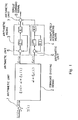
- FIG. 1 is a block diagram of an embodiment according to the present invention. Since digital processing is carried out in this embodiment, the block diagram is shown as a discrete system.
- FIG. 1 corresponds to the integrator 14 shown in FIG. 5 (which is indicated by A in FIG. 5).
- the integrator 14 of FIG. 5 may be expressed as a discrete system as shown in FIG. 2.
- Denoted at 1 in FIG. 1 is an arithmetic unit for calculating and issuing the difference between a speed command u(i) from a converter (not shown) and a speed feedback signal Y(-i) from a servomotor.
- a command dividing means 2 serves to divide a difference output signal ⁇ (i) from the arithmetic unit 1 into:
- An output signal from the command dividing means 2 is applied to an integrating means 3 and an incompletely integrating means 4.
- the remaining amount ⁇ 1 (i) is generated when the command value is large, and is subjected to conventional integration.
- the integrating means 3 comprises an arithmetic unit 5, a Z function Z -1 , and a gain kl, and has the same function as that of the integrator 14 shown in FIG. 5. Since the integrating means 3 actually processes the signal as a discrete system, it effects the same processing as that of the block A in FIG . 2. Therefore, when the command value is large, the processing is the same as the conventional process.
- the gain kl is of the same value as that shown in FIG. 5.
- the minute amount ⁇ 2 (i) is applied to the incompletely integrating means 4.
- the incompletely integrating means 4 is composed of an arithmetic unit 6, a Z function Z - 1 , a gain k2, and a feedback gain k3 for the Z function Z- 1 .
- the output from the integrating means 3 is held even if a position feed signal is fed back to reduce a speed deviation signal to zero, whereas the output of the incompletely integrating means 4 is exponentially reduced when the speed deviation signal is reduced to zero.
- the output signal from the integrating means 3 and the output signal from the incompletely integrating means 4 are added by an arithmetic unit 7 , which issues the sum as a torque command signal.
- the speed deviation signal is divided by the signal dividing means 2 and processed by the incompletely integrating means 4. Therefore, when the speed deviation signal is fed back to eliminate or reduce the speed deviation, the torque command signal is reduced, and excessive movement of the servomotor is suppressed, so that the accuracy of actual movement with respect to the minute command is increased.
- the position command is large, the remaining amount of the speed deviation is large and processed by the conventional integrating means 3 without lowering a speed gain.
- FIG. 3 shows a flowchart of processing operation of the command dividing means 2.
- This step determines whether or not the absolute value
- the speed deviation input ⁇ (i) is issued as it is as a minute amount ⁇ 2 (i).
- the speed deviation is larger than a minute amount, and it is first determined whether the speed deviation is positive or negative, because the speed deviation is either positive or negative dependent on whether the position command is positive or negative. If the speed deviation e(i) is positive, then control proceeds to a step 4 (S 4 ), and if the speed deviation ⁇ (i) is negative, then control goes to a step 5 (S5).
- the speed deviation ⁇ (i) can thus be divided into a minute amount and a remaining amount by the above steps.
- the hardware of the present embodiment can easily be implemented by a known microcomputer.
- FIG. 4 Results of an experiment conducted on the present embodiment are shown in FIG. 4, which is similar to FIG. 6.
- the straight line M1 represents ideal movement of a mechanical movable member
- the polygonal line M3 indicates movement of the mechanical movable member controlled by the embodiment of the present invention.
- Comparison between the polygonal line M3 and the polygonal line M2 shown in FIG. 6 indicates that movement of the mechanical movable member according to the present invention is improved.
- the speed deviation is divided into a minute amount and a remaining amount as defined in advance, and the minute amount is incompletely integrated whereas the remaining amount is integrated.
- the amounts thus integrated are added, and the sum is used as a torque command signal. Therefore, positioning control can be effected without reducing a speed gain in response to a large position command, and precise movement can be achieved in response to a minute position command.
Abstract
A position control system receives a commanded speed (uli) and an actual speed (Yci), calculates a speed deviation (E(i)) by an arithmetic unit (1), and outputs a torque command signal (8) to a motor. A command dividing means (2) is provided, which divides the speed deviation (E(i)) into a predetermined small amount (2) and a remaining amount (E1(i)=E(i)-d). The former is incompletely integrated (4), whereas the latter is integrated (3). The two results are added by an arithmetic unit (7) to give the torque command signal (8).
Description
- The present invention relates to a position control system for a servomotor or the like, and more particularly to a position control system for precisely controlling fine positioning operation without lowering a speed gain.
- Positioning operation in a numerical control apparatus or the like requires that a movable member be precisely responsive to a fine positioning command.
- A control system for a servomotor to effect such positioning operation is illustrated in FIG. 5. Denoted at 11 is an arithmetic unit for adding a
position command 21 and subtracting aposition feedback signal 22. Aconverter 12 with a position gain K converts a position command issued from thearithmetic unit 11 to a speed command (u(s)) 23. Anarithmetic unit 13 issues a signal indicating the difference between thespeed command 23 and a speed feedback signal. Anintegrator 14 with an integration constant kl integrates the speed command. Designated at 15 is an arithmetic unit for issuing a signal representing the difference between a torque command from the integrator 14 and a torque feedback command which is produced by multiplying aspeed feedback signal 24 by a proportional gain. Acurrent control circuit 16 issues a current dependent on the torque command. Thereference numeral 17 represents a servomotor. Kt indicates a torque constant, Jm the inertia of the servomotor, 24 a speed output from the servomotor, and 25 a position output from the servomotor. Thespeed output 24 is fed back directly to thearithmetic unit 13 and also fed back to thearithmetic unit 11 after being multiplied by a proportional gain k2. The position output 25 of the servomotor is fed back to thearithmetic unit 11. - Operation of the servo system thus constructed is shown in FIG. 6. The graph of FIG. 6 has a horizontal axis indicating a movement command in a unit of 1 µm and a vertical axis representing actual movement of a mechanical movable member in a unit of 1 µm. Ideally, a mechanical movable member would move precisely 1 µm each time a command for 1 µm is applied, as indicated by the straight line M1.
- Actually, however, as indicated by the polygonal line M2, a mechanical movable member moves 0.2 µm at a time in response to a command for 1 µm and moves 1.8 µm at a time in response to a command for 1 µm, for example, and hence does not move in exact response to applied commands, thus resulting in a so-called stick/slip phenomenon. This phenomenon is responsible for a reduction in the accuracy of actual operation of the mechanical movable member and for a poor finishing surface.
- The causes of such undesirable conditions will be analyzed below. FIG. 7 shows the torque command illustrated in FIG. 5. The graph of FIG. 7 has a horizontal axis indicative of time (t) and a vertical axis of torque (T). When a
position command 21 for 1 µm is applied, thetorque command 23 issued from theintegrator 14 of FIG. 5 increases along a straight line Cl as shown in FIG. 7. when the torque exceeds a static friction torque Ce, theservomotor 17 starts rotating. There is a considerable period of time before a position output is actually fed back. During that period of time, the torque command increases. When the servomotor starts to rotate, the servomotor moves beyond the command value since a dynamic friction torque is much smaller than the static friction torque. As a result, the amount of movement when a next command for 1 µm is applied becomes smaller than 1 µm. - To solve the above problem, the integration constant k1 of the
integrator 14 shown in FIG. 5 may be made small to cause the torque to increase along a curve C2 as shown in FIG. 7, so that the torque increases more gradually. However, such a solution is still problematic in that when the position command is large, the response of the entire system is slow. - It is an object of the present invention to provide a position control system for precisely controlling fine positioning operation without lowering a speed gain.
- In order to eliminate the aforesaid problems, there is provided in accordance with the present invention a position control system having a speed control loop for generating a torque command signal for a motor from the speed deviation between a speed command and an actual speed, said position control system comprising:
- command dividing means for dividing said speed deviation into a minute amount and a remaining amount which are defined in advance;
- integrating means for integrating said remaining amount;
- incompletely integrating means for incompletely integrating said minute amount; and
- arithmetic means for adding an output from said integrating means and an output from said incompletely integrating means, and issuing the sum as a torque command signal.
- Since the speed deviation is divided into a minute amount and a remaining amount, when the command value is minute, the gradient of a torque curve is virtually reduced by the incompletely integrating means.
- When the command value is large, there is a remaining amount, and the torque increases along the conventional torque curve.
- Therefore, the torque curve varies according to the command value.
-
- FIG. 1 is a block diagram of an embodiment of the present invention;
- FIG. 2 is a block diagram showing a conventional torque command integrator as a discrete system;
- FIG. 3 is a flowchart of operation of a command dividing means according to the embodiment of the invention;
- FIG. 4 is a diagram showing a fine positioning command and an actual movement of a mechanical movable member according to the embodiment of the invention;
- FIG. 5 is a diagram showing a conventional servomotor position control system as an analog system;
- FIG. 6 is a diagram illustrating a fine positioning command and an actual movement of a mechanical movable member according to the conventional system; and
- FIG. 7 is a diagram showing the relationship between a torque command increase and a static friction torque.
- An embodiment of the present invention will hereinafter be described in specific detail with reference to the drawings.
- FIG. 1 is a block diagram of an embodiment according to the present invention. Since digital processing is carried out in this embodiment, the block diagram is shown as a discrete system. FIG. 1 corresponds to the
integrator 14 shown in FIG. 5 (which is indicated by A in FIG. 5). Theintegrator 14 of FIG. 5 may be expressed as a discrete system as shown in FIG. 2. - Denoted at 1 in FIG. 1 is an arithmetic unit for calculating and issuing the difference between a speed command u(i) from a converter (not shown) and a speed feedback signal Y(-i) from a servomotor.
- A command dividing means 2 serves to divide a difference output signal ε(i) from the
arithmetic unit 1 into: - a minute amount ε2(i) = a
- a remaining amount ε1(i) - ε(i) - α
- An output signal from the command dividing
means 2 is applied to anintegrating means 3 and an incompletely integrating means 4. - The remaining amount ε1(i) is generated when the command value is large, and is subjected to conventional integration. The integrating means 3 comprises an
arithmetic unit 5, a Z function Z-1, and a gain kl, and has the same function as that of theintegrator 14 shown in FIG. 5. Since the integratingmeans 3 actually processes the signal as a discrete system, it effects the same processing as that of the block A in FIG. 2. Therefore, when the command value is large, the processing is the same as the conventional process. The gain kl is of the same value as that shown in FIG. 5. - The minute amount ε2(i) is applied to the incompletely integrating means 4. The incompletely integrating means 4 is composed of an
arithmetic unit 6, a Z function Z-1, a gain k2, and a feedback gain k3 for the Z function Z-1. The output from the integrating means 3 is held even if a position feed signal is fed back to reduce a speed deviation signal to zero, whereas the output of the incompletely integrating means 4 is exponentially reduced when the speed deviation signal is reduced to zero. The output signal from the integratingmeans 3 and the output signal from the incompletely integrating means 4 are added by an arithmetic unit 7, which issues the sum as a torque command signal. - As described above, if the position command signal is minute, the speed deviation signal is divided by the signal dividing means 2 and processed by the incompletely integrating means 4. Therefore, when the speed deviation signal is fed back to eliminate or reduce the speed deviation, the torque command signal is reduced, and excessive movement of the servomotor is suppressed, so that the accuracy of actual movement with respect to the minute command is increased.
- If the position command is large, the remaining amount of the speed deviation is large and processed by the conventional integrating
means 3 without lowering a speed gain. - Consequently, there is established a system wherein the speed gain is virtually small for a minute position command and the speed gain remains the same as conventional for normal position commands.
- Processing operation of the command dividing means 2 will be described below. FIG. 3 shows a flowchart of processing operation of the command dividing means 2.
- This step determines whether or not the absolute value |ε(i)| of the speed deviation ε(i) is equal to or greater than a minute amount a. If it is equal to or greater than the minute amount a, then control goes to a
step 3. If it is smaller than the minute amount a, i.e., if the position command is of a minute amount, then control goes to astep 2. - The speed deviation input ε(i) is issued as it is as a minute amount ε2(i).
- In this step, the speed deviation is larger than a minute amount, and it is first determined whether the speed deviation is positive or negative, because the speed deviation is either positive or negative dependent on whether the position command is positive or negative. If the speed deviation e(i) is positive, then control proceeds to a step 4 (S4), and if the speed deviation ε(i) is negative, then control goes to a step 5 (S5).
- Since the speed deviation ε(i) is positive, it is divided into a remaining amount and a minute amount according to the following equations:
- a remaining amount ε1(i) = ε(i) - α
- a minute amount ε2(i) = α
- Since the speed deviation s(i) is negative, it is divided into a remaining amount and a minute amount according to the following equations:
- a remaining amount ε1(i) - s(i) + α
- a minute amount ε2(i) = - α
- The speed deviation ε(i) can thus be divided into a minute amount and a remaining amount by the above steps.
- The hardware of the present embodiment can easily be implemented by a known microcomputer.
- Results of an experiment conducted on the present embodiment are shown in FIG. 4, which is similar to FIG. 6. The straight line M1 represents ideal movement of a mechanical movable member, and the polygonal line M3 indicates movement of the mechanical movable member controlled by the embodiment of the present invention. Comparison between the polygonal line M3 and the polygonal line M2 shown in FIG. 6 indicates that movement of the mechanical movable member according to the present invention is improved.
- While in the above embodiment the speed deviation is always divided into a minute amount and a remaining amount even when it is large, it is possible to process the speed deviation only as a remaining amount when it is large.
- With the present invention, as described above, the speed deviation is divided into a minute amount and a remaining amount as defined in advance, and the minute amount is incompletely integrated whereas the remaining amount is integrated. The amounts thus integrated are added, and the sum is used as a torque command signal. Therefore, positioning control can be effected without reducing a speed gain in response to a large position command, and precise movement can be achieved in response to a minute position command.
Generally, a is selected to be of a value in the vicinity of a speed deviation corresponding to a minimum detected unit or a minimum command unit (1 µm) of a position feedback system, and is experimentally determined through observation of a minute movement amount command and an actual movement amount as shown in FIG. 6.
Claims (2)
1. A position control system.having a speed control loop for generating a torque command signal for a motor from the speed deviation between a speed command and an actual speed, said position control system comprising:
command dividing means for dividing said speed deviation into a minute amount and a remaining amount which are defined in advance;
integrating means for integrating said remaining amount;
incompletely integrating means for incompletely integrating said minute amount; and
arithmetic means for adding an output from said integrating means and an output from said incompletely integrating means, and issuing the sum as a torque command signal.
2. A position control system according to claim 1, wherein said integrating means and said incompletely integrating means are arranged to process the amounts with a discrete system.
Applications Claiming Priority (2)
| Application Number | Priority Date | Filing Date | Title |
|---|---|---|---|
| JP269445/86 | 1986-11-12 | ||
| JP61269445A JPS63123107A (en) | 1986-11-12 | 1986-11-12 | Position control system |
Publications (2)
| Publication Number | Publication Date |
|---|---|
| EP0289626A1 true EP0289626A1 (en) | 1988-11-09 |
| EP0289626A4 EP0289626A4 (en) | 1990-04-10 |
Family
ID=17472532
Family Applications (1)
| Application Number | Title | Priority Date | Filing Date |
|---|---|---|---|
| EP19870907523 Withdrawn EP0289626A4 (en) | 1986-11-12 | 1987-11-11 | Position control system. |
Country Status (5)
| Country | Link |
|---|---|
| US (1) | US4887015A (en) |
| EP (1) | EP0289626A4 (en) |
| JP (1) | JPS63123107A (en) |
| KR (1) | KR910006498B1 (en) |
| WO (1) | WO1988003678A1 (en) |
Cited By (4)
| Publication number | Priority date | Publication date | Assignee | Title |
|---|---|---|---|---|
| FR2642866A1 (en) * | 1989-01-11 | 1990-08-10 | Inst Mash Im | METHOD FOR CONTROLLING A RESONANCE MECHANICAL ARM |
| WO1991005297A1 (en) * | 1989-09-26 | 1991-04-18 | Robert Bosch Gmbh | Process for regulating a setting system subject to friction |
| DE4411390A1 (en) * | 1993-04-01 | 1994-10-06 | Mitsubishi Electric Corp | Position command method and device for a controlled object |
| US5694016A (en) * | 1989-09-26 | 1997-12-02 | Robert Bosch Gmbh | Method for controlling a servo system having friction |
Families Citing this family (12)
| Publication number | Priority date | Publication date | Assignee | Title |
|---|---|---|---|---|
| JPH02297602A (en) * | 1989-05-12 | 1990-12-10 | Fanuc Ltd | Sliding mode control system including nonlinear item compensation |
| JP2566665B2 (en) * | 1990-06-27 | 1996-12-25 | 川崎重工業株式会社 | Robot controller in inertial system |
| JP3230831B2 (en) * | 1992-01-28 | 2001-11-19 | オークマ株式会社 | Motor drive control device |
| JP2833730B2 (en) * | 1993-03-10 | 1998-12-09 | 三菱電機株式会社 | Position control device |
| JP3285681B2 (en) * | 1993-04-28 | 2002-05-27 | ファナック株式会社 | Servo motor control method |
| JP3129173B2 (en) * | 1995-11-20 | 2001-01-29 | 富士電機株式会社 | AC motor control device |
| JP3628119B2 (en) * | 1996-07-24 | 2005-03-09 | ファナック株式会社 | Servo motor control method |
| GB2354087B (en) * | 1999-05-14 | 2003-04-02 | Mitsubishi Electric Corp | Servo control apparatus |
| JP4459674B2 (en) * | 2004-03-23 | 2010-04-28 | 本田技研工業株式会社 | Plant control system using modulation algorithm |
| DE102004016733B4 (en) * | 2004-04-05 | 2006-06-08 | Siemens Ag | Motor control device and corresponding control method |
| JP4397868B2 (en) * | 2005-09-13 | 2010-01-13 | 本田技研工業株式会社 | Plant control device using PWM algorithm |
| US8775003B2 (en) * | 2012-11-28 | 2014-07-08 | GM Global Technology Operations LLC | Methods and systems for controlling a proportional integrator |
Citations (2)
| Publication number | Priority date | Publication date | Assignee | Title |
|---|---|---|---|---|
| US3958109A (en) * | 1975-01-20 | 1976-05-18 | The United States Of America As Represented By The Secretary Of The Navy | Universal modularized digital controller |
| EP0290618A1 (en) * | 1986-11-08 | 1988-11-17 | Fanuc Ltd. | Digital servo system |
Family Cites Families (2)
| Publication number | Priority date | Publication date | Assignee | Title |
|---|---|---|---|---|
| JPS55160871A (en) * | 1979-04-27 | 1980-12-15 | Nissan Motor Co Ltd | Ground speed radar for vehicle equipped with radio wave interference avoiding apparatus |
| JPS59191621A (en) * | 1983-04-15 | 1984-10-30 | Mitsubishi Electric Corp | Servo device |
-
1986
- 1986-11-12 JP JP61269445A patent/JPS63123107A/en active Pending
-
1987
- 1987-11-11 KR KR1019880700811A patent/KR910006498B1/en not_active IP Right Cessation
- 1987-11-11 EP EP19870907523 patent/EP0289626A4/en not_active Withdrawn
- 1987-11-11 US US07/221,243 patent/US4887015A/en not_active Expired - Fee Related
- 1987-11-11 WO PCT/JP1987/000875 patent/WO1988003678A1/en not_active Application Discontinuation
Patent Citations (2)
| Publication number | Priority date | Publication date | Assignee | Title |
|---|---|---|---|---|
| US3958109A (en) * | 1975-01-20 | 1976-05-18 | The United States Of America As Represented By The Secretary Of The Navy | Universal modularized digital controller |
| EP0290618A1 (en) * | 1986-11-08 | 1988-11-17 | Fanuc Ltd. | Digital servo system |
Non-Patent Citations (1)
| Title |
|---|
| See also references of WO8803678A1 * |
Cited By (5)
| Publication number | Priority date | Publication date | Assignee | Title |
|---|---|---|---|---|
| FR2642866A1 (en) * | 1989-01-11 | 1990-08-10 | Inst Mash Im | METHOD FOR CONTROLLING A RESONANCE MECHANICAL ARM |
| WO1991005297A1 (en) * | 1989-09-26 | 1991-04-18 | Robert Bosch Gmbh | Process for regulating a setting system subject to friction |
| US5694016A (en) * | 1989-09-26 | 1997-12-02 | Robert Bosch Gmbh | Method for controlling a servo system having friction |
| DE4411390A1 (en) * | 1993-04-01 | 1994-10-06 | Mitsubishi Electric Corp | Position command method and device for a controlled object |
| DE4411390C2 (en) * | 1993-04-01 | 2003-06-18 | Mitsubishi Electric Corp | Positioning method and device for an object to be controlled |
Also Published As
| Publication number | Publication date |
|---|---|
| JPS63123107A (en) | 1988-05-26 |
| WO1988003678A1 (en) | 1988-05-19 |
| KR910006498B1 (en) | 1991-08-27 |
| KR890700240A (en) | 1989-03-10 |
| US4887015A (en) | 1989-12-12 |
| EP0289626A4 (en) | 1990-04-10 |
Similar Documents
| Publication | Publication Date | Title |
|---|---|---|
| EP0289626A1 (en) | Position control system | |
| EP1120698B1 (en) | Position controller | |
| US4143310A (en) | Apparatus for positioning | |
| US4663703A (en) | Predictive model reference adaptive controller | |
| JP3129622B2 (en) | Quadrant projection correction method in full closed loop system | |
| EP0384437B1 (en) | Method and system for changing control parameters in accordance with state of process in process control | |
| EP0089156B1 (en) | Method and apparatus for controlling acceleration and/or deceleration | |
| EP0433461A1 (en) | Zeroing method using a disturbance estimating observer | |
| US4609988A (en) | Automatic prediction and capture of a preselected altitude for aircraft | |
| US4701686A (en) | Line tracking control method | |
| US4667079A (en) | Electrode retraction control system of electric discharge machine | |
| US6020706A (en) | Method of and apparatus for controlling a servomotor | |
| US6122998A (en) | Force control method for a bar feeder of a lathe | |
| JPH0424198B2 (en) | ||
| EP0428742A1 (en) | Method of sliding mode control | |
| KR0160997B1 (en) | Compensation method for servo-worm up drift in robot position control system | |
| EP0604663A1 (en) | Method for estimating inertia and disturbance torque, and method for detecting abnormal load | |
| JP2681969B2 (en) | Coulomb friction compensation method by variable structure system | |
| JPS62150409A (en) | Speed control method in digital servo control | |
| JPS6048505A (en) | Backlash correcting device | |
| JPS60164805A (en) | Process controller | |
| JPS6015718A (en) | Speed servo control method | |
| JPH0229420B2 (en) | RENCHUKINIOKERUIGATANAIYUMENREBERUSEIGYOHOHO | |
| RU2020533C1 (en) | Regulator | |
| JP2653130B2 (en) | Acceleration / deceleration control device |
Legal Events
| Date | Code | Title | Description |
|---|---|---|---|
| PUAI | Public reference made under article 153(3) epc to a published international application that has entered the european phase |
Free format text: ORIGINAL CODE: 0009012 |
|
| 17P | Request for examination filed |
Effective date: 19880728 |
|
| AK | Designated contracting states |
Kind code of ref document: A1 Designated state(s): DE FR GB |
|
| A4 | Supplementary search report drawn up and despatched |
Effective date: 19900410 |
|
| RHK1 | Main classification (correction) |
Ipc: G05B 19/19 |
|
| 17Q | First examination report despatched |
Effective date: 19920124 |
|
| STAA | Information on the status of an ep patent application or granted ep patent |
Free format text: STATUS: THE APPLICATION IS DEEMED TO BE WITHDRAWN |
|
| 18D | Application deemed to be withdrawn |
Effective date: 19920604 |