EP0292175A2 - Air/Fuel ratio control system for internal combustion engine - Google Patents
Air/Fuel ratio control system for internal combustion engine Download PDFInfo
- Publication number
- EP0292175A2 EP0292175A2 EP88304197A EP88304197A EP0292175A2 EP 0292175 A2 EP0292175 A2 EP 0292175A2 EP 88304197 A EP88304197 A EP 88304197A EP 88304197 A EP88304197 A EP 88304197A EP 0292175 A2 EP0292175 A2 EP 0292175A2
- Authority
- EP
- European Patent Office
- Prior art keywords
- air
- value
- fuel ratio
- sensor
- oxygen density
- Prior art date
- Legal status (The legal status is an assumption and is not a legal conclusion. Google has not performed a legal analysis and makes no representation as to the accuracy of the status listed.)
- Granted
Links
Images


Classifications
-
- F—MECHANICAL ENGINEERING; LIGHTING; HEATING; WEAPONS; BLASTING
- F02—COMBUSTION ENGINES; HOT-GAS OR COMBUSTION-PRODUCT ENGINE PLANTS
- F02D—CONTROLLING COMBUSTION ENGINES
- F02D41/00—Electrical control of supply of combustible mixture or its constituents
- F02D41/02—Circuit arrangements for generating control signals
- F02D41/14—Introducing closed-loop corrections
- F02D41/1438—Introducing closed-loop corrections using means for determining characteristics of the combustion gases; Sensors therefor
- F02D41/1439—Introducing closed-loop corrections using means for determining characteristics of the combustion gases; Sensors therefor characterised by the position of the sensor
- F02D41/1441—Plural sensors
-
- F—MECHANICAL ENGINEERING; LIGHTING; HEATING; WEAPONS; BLASTING
- F02—COMBUSTION ENGINES; HOT-GAS OR COMBUSTION-PRODUCT ENGINE PLANTS
- F02D—CONTROLLING COMBUSTION ENGINES
- F02D41/00—Electrical control of supply of combustible mixture or its constituents
- F02D41/02—Circuit arrangements for generating control signals
- F02D41/14—Introducing closed-loop corrections
- F02D41/1438—Introducing closed-loop corrections using means for determining characteristics of the combustion gases; Sensors therefor
- F02D41/1477—Introducing closed-loop corrections using means for determining characteristics of the combustion gases; Sensors therefor characterised by the regulation circuit or part of it,(e.g. comparator, PI regulator, output)
- F02D41/1479—Using a comparator with variable reference
Definitions
- This invention relates to an air/fuel ratio control system for an internal combustion engine, which controls the air/fuel ratio of the internal combustion engine by using, as feedback signals, detection signals from oxygen density sensors (hereinafter called “0 2 sensors”) arranged in the exhaust system of the internal combustion engine which may hereinafter be called “engine” as needed.
- 0 2 sensors oxygen density sensors
- air/fuel ratio control systems of the above sort for internal combustion engines
- an 0 2 sensor which has been designed to change its output value abruptly near the stoichiometric fuel ratio by using the principle of oxygen concentration cells of a solid electrolyte, is arranged in an engine exhaust system at an upstream side relative to the point of arrangement of a catalytic converter (three-way catalyst) in the engine exhaust system.
- the air/fuel ratio of the internal combustion engine is controlled by comparing an output from the 0 2 sensor with a predetermined standard value (As the standard value, an intermediate value of values between which the abrupt change takes place is given as a fixed value.
- This value is useful as a value for the judgement of either a rich air-fuel mixture or a lean air-fuel mixture) and then controlling the quantity of the fuel to be injected from each electromagnetic fuel injection valve (injector) in such a way that the air-fuel mixture is rendered lean when the output of the 0 2 sensor is greater than the standard value but is rendered rich when the output of the 0 2 sensor becomes smaller on the contrary.
- the standard value to be compared with the output of the forward 0 2 sensor is a fixed value no matter whether they are of the former type or of the latter type. They hence involve a problem in connection with the reliability of the control, since the characteristics of 0 2 sensors vary from one sensor to another and also along the passage of time, the accuracy of the control varies, and the efficiency of cleaning of exhaust gas by the catalytic converter also changes.
- an object of this invention is to provide an air/fuel ratio control system for an internal combustion engine, which allows to change, based on outputs from a forward 0 2 sensor and a rearward 0 2 sensor provided inside or on a downstream side of a catalytic converter, a standard value to be compared with an output from one of the forward and rearward 0 2 sensors, whereby the accuracy of the control is not changed by variations in characteristics of each 0 2 sensor and changes of its characteristics along the passage of time and the efficiency of cleaning of exhaust gas by the catalytic converter can also be maintained high, thereby making it possible to obtain high reliability in regard to the control.
- Another object of this invention is to provide an air/fuel ratio control system for an internal combustion engine, which allows to change, based on outputs from both forward 0 2 sensor and rearward 0 2 sensor, a second standard value to be compared with an output from the other one of the forward and rearward 0 2 sensors so as to obtain high reliability with respect to the control.
- an air/fuel ratio control system for an internal combustion engine comprising:
- Said standard-value changing means may change the air/fuel ratio between a rich side and a lean side relative to a stoichiometric air/fuel ratio, detect outputs from the first and second oxygen density sensors at each air/fuel ratio upon changing the air/fuel ratio, and then change the standard value on the basis of a difference in output between the first oxygen density sensor and second oxygen density sensor.
- said standard-value changing means may change the standard value at intervals of a predetermined period of operation time.
- said standard-value changing means may change the air/fuel ratio between a rich side and a lean side relative to a stoichiometric air/fuel ratio, detect outputs from the first and second oxygen density sensors at each air/fuel ratio upon changing the air / fuel ratio, and change and renew the standard value by a median of outputs from said one oxygen density sensor in a range where a corresponding output characteristic curve obtained as a result of the detection has an inclination greater than a predetermined inclination.
- an air/fuel ratio control system for an internal combustion engine comprising:
- Said second standard-value changing means may change the air/fuel ratio between a rich side and a lean side relative to a stoichiometric air/fuel ratio, detect outputs from the first and second oxygen density sensors at each air/fuel ratio upon changing the air/fuel ratio, and change and renew the second standard value by a value pertaining to an output of the other oxygen density sensor, said output corresponding to the median of outputs from said one oxygen density sensor in a range where a corresponding output characteristic curve obtained as a result of the detection has an inclination greater than a predetermined inclination.
- Said second standard-value changing means may change the second standard value at intervals of a predetermined period of operation time.
- a correction may be effected to any one of at least response delay time, proportional gain and integral gain on the basis of results of comparison between the second standard value and an output from the other oxygen density sensor.
- a correction may also be effected to the standard value on the basis of results of comparison between the second standard value and an output from the other oxygen density sensor.
- said air/fuel ratio control correcting means may use the average value of outputs from the other oxygen density sensor as the output from the other oxygen density sensor, and the average value of the outputs being renewed whenever the output value of said one oxygen density sensor is reversed.
- a correction may be effected to the air/fuel control by said air/fuel control means on the basis of results of comparison between the second standard value and the average value of the outputs from the other oxygen density sensor, when the number of reversals of the output value from said one oxygen density sensor has exceeded a predetermined value.
- Said air/fuel ratio control correction means may use the average value of outputs from the other oxygen density sensor as the output from the other oxygen density sensor, and the average value of the outputs may be renewed whenever the quantity of intake air of the internal combustion engine exceeds a first predetermined value.
- a correction may be effected to the air/fuel ratio control by said air/fuel ratio control means on the basis of results of comparison between the second standard value and the average value of the outputs from the other oxygen density sensor.
- an air/fuel ratio control system for an internal combustion engine comprising:
- the reference value for rich/lean judgement which is to be compared with an output from the upstream-side, namely, forward oxygen density sensor relative to the catalytic converter, can be changed on the basis of outputs from both forward oxygen density sensor and downstream-side, i.e., rearward oxygen density sensor.
- the accuracy of the control is not changed by variations in characteristics of each oxygen density sensor and changes of its characteristics along the passage of time and the efficiency of cleaning of exhaust gas by the catalytic converter can be maintained high, thereby bringing about an advantage that high reliability is assured in regard to the control.
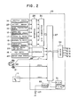
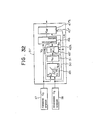
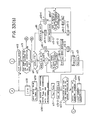
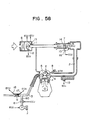
- FIG. 3 An engine system controlled by the system of this invention may be illustrated as shown in FIG. 3, in which an engine E has an intake passage 2 and an exhaust passage 3, both, communicated to a combustion chamber 1.
- the communication between the intake passage 2 and combustion chamber 1 is controlled by an intake valve 4, while that of the discharge passage 3 with the combustion chamber 1 is controlled by an exhaust valve 5.
- the intake passage 2 is provided with an air cleaner 6, a throttle valve 7 and an electromagnetic fuel injection valve (solenoid valve) 8 in order from the upstream side thereof.
- the exhaust passage 3 is provided with a catalytic converter (three-way catalyst) 9 for cleaning exhaust gas and an unillustrated muffler in order from the upstream side thereof.
- solenoid valves of the same type as the solenoid valve 8 are provided as many as the number of cylinders in an intake manifold portion.
- the engine E is an in- line 4-cylinder engine in the present embodiment.
- Four solenoid valves 8 are hence provided.
- the engine E can be said to be an engine of the so-called multi-point fuel injection (MPI) system.
- MPI multi-point fuel injection
- the throttle valve 7 is connected via an unillustrated wire cable to an accelerator pedal (not shown) so that the opening rate of the throttle valve 7 changes in accordance with the degree of depression of the accelerator pedal.
- the throttle valve 7 is also driven by an idling speed control motor (ISC motor), whereby the opening rate of the throttle valve 7 can be varied without need for depression of the accelerator pedal upon idling.
- ISC motor idling speed control motor
- air which has been drawn in accordance with the opening rate of the throttle valve 7 through the air cleaner 6 is mixed with a fuel from the solenoid valve 8 in the intake manifold portion so as to give a suitable air/fuel ratio.
- the resulting air-fuel mixture is ignited at suitable timing by an unillustrated spark plug in the combustion chamber 1, so that the air-fuel mixture is caused to burn.
- the air-fuel mixture is discharged as exhaust gas into the exhaust passage 3 and subsequent to cleaning of three noxious components CO, HC, NO x in the exhaust gas by the catalytic converter 9, the exhaust gas is reduced in noise by an unillustrated muffler and then released into the surrounding atmosphere.
- a variety of sensors is provided in order to control the engine E.
- an airflow sensor 11 for detecting the quantity of intake air from Karman vortex information
- an intake air temperature sensor 12 for detecting the temperature of the air drawn
- a barometric pressure sensor 13 all, in the portion where the air cleaner is provided.
- a throttle sensor 14 of the potentiometer type said throttle sensor 14 being adapted to detect the opening rate of the throttle valve 17, an idle switch 15 for detecting the state of idling, and a motor position sensor 16 for detecting the position of the ISC motor 10.
- a forward 0 2 sensor 17 as a first oxygen density sensor for detecting the oxygen (0 2 ) density in the exhaust gas is provided first of all at a position upstream of the catalytic converter 9, and a rearward O2 sensor 18 as a second oxygen density sensor for also detecting the O2 density in the exhaust gas is then arranged at a position downstream of the catalytic converter 9.
- the forward 0 2 sensor 17 and rearward 0 2 sensor 18 both make use of the principle of oxygen concentration cells of a solid electrolyte. They have such a characteristic that their output voltages change abruptly near the stoichiometric air/fuel ratio. Their voltages are low on the side leaner than the stoichiometric air/fuei ratio but high on the side richer than the stoichiometric air/fuel ratio.
- the rearward 0 2 sensor 18 may be provided inside the catalytic converter 9.
- a crank angle sensor 21 for detecting the crank angle (which also serves as a revolutionary speed sensor for detecting the revolutionary speed of the engine) and a TDC sensor 22 for detecting the top dead center of a first cylinder (base cylinder) are also provided with the distributor.
- Detection signals from these sensors 11-22 are inputted to an electronic control unit (ECU) 23.
- ECU electronice control unit
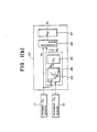
- the hardware construction of the ECU 23 may be illustrated as shown in FIG. 2.
- the ECU 23 is equipped with a CPU 27 as its main element.
- the CPU 27 is fed with detection signals from the intake air temperature sensor 12, barometric sensor 13, throttle sensor 14, forward O2 sensor 17, rearward 0 2 sensor 18 and battery sensor 25 by way of an input interface 28 and/or an A/D converter 30.
- Detection signals from the idle sensor 15, vehicle speed sensor 20 and ignition switch 26 are also inputted through an input interface 29, while detection signals from the air flow sensor 11, crank angle sensor 21 and TDC sensor 22 are inputted directly to the input port.
- the CPU 27 performs transfer of data with an ROM 31 which serves to store program data and fixed-value data, an RAM which is renewed and rewritten sequentially, and a battery backed-up RAM (BURAM) 33 which is backed up by the battery 24 to maintain its contents while the battery 24 is connected.
- ROM 31 which serves to store program data and fixed-value data
- RAM which is renewed and rewritten sequentially
- BURAM battery backed-up RAM
- the RAM 32 is designed in such a way that data stored therein are erased and reset when the ignition switch 26 is turned off.
- a fuel injection control signal which has been computed in a manner to be described subsequently is ouputted via a driver 34, whereby the 4 solenoid valves 8 by way of example are successively actuated.
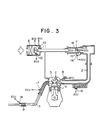
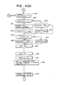
- FIG. 1 (a) A function block diagram of such a fuel injection control (the control of the drive time of each solenoid valve) may be illustrated as shown in FIG. 1 (a).
- the ECU 23 is equipped with a basic energization time determination means 35 for determining the basic drive time T B for the solenoid valves 8.
- the basic energization time determination means 35 determines information on the intake air volume per revolution of the engine (Q/Ne) on the basis of information on an intake air quantity Q from the airflow sensor 11 and information on engine revolutionary speed Ne from the crank angle sensor 21 and then determines a basic drive time T B on the basis of the information.
- an air/fuel ratio upward correction means 36 for performing an upward correction of the air/fuel ratio in accordance with the revolutionary speed of the engine and the engine load (the above Q/Ne information contains engine load information) and an 0 2 sensor feedback correction means 37 for conducting corrections of the O2 sensors by setting a correction factor K AF upon performing the feedback control of the O 2 sensors.
- Either one of the air / fuel ratio upward correction means 36 and O 2 sensor feedback correction means 37 is selected by switching means 38,39 which are changed over in a mutually-interlocked manner.
- a water-temperature-dependent correction means 40 for setting a correction factor K WT in accordance with the temperature of the cooling water for the engine, an intake-air-temperature-dependent correction means 41 for setting a correction factor K AT in accordance with the temperature of the air drawn, a barometric-pressure-dependent correction means 42 for setting a correction factor K AP in accordance with the barometric pressure, an accelerating-fuel-increment correction means 43 for setting a correction factor K Ac for the increment of fuel quantity for acceleration, and a dead time correction means 44 for setting a dead time (ineffective time) To for correcting the drive time in accordance with the voltage of the battery.
- the drive time T INJ of the solenoid valve 8 is eventually expressed by T B x Kwr x K AT X K AP x K AC x K AF + To and the solenoid valve 8 is actuated for the drive time T INJ .
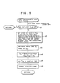
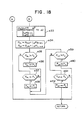
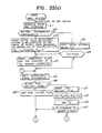
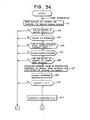
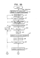
- Step b1 The procedure of such a control of the actuation of the solenoid valve may be illustrated like the flowchart of FIG. 5.
- the routine of the flow chart shown in FIG. 5 is performed by a crank pulse interruption which takes place every 180°.
- Step b1 it is judged in Step b1 whether a fuel cut-off flag has been set up or not. Where the fuel cut-off flag has been set up, no fuel injection is required and the routine returns. Otherwise, an intake air quantity Q CR (Q/Ne) per 180° crank angle is set up in Step b2 on the basis of data on the number of Karman pulses produced between the last crank pulse and the present crank pulse and the period between the Karman pulses.
- Step b3 the basic drive time T is set up in accordance with the Q CR .
- the solenoid valve drive time T INJ is then determined in Step b4 by computing it in accordance with T B x K WT x K AT x K A p X K AC x K AF + To.
- the T INJ is set in an injection timer in Step b5 and is then triggered in Step b6. By this trigger, the fuel is injected only for the time T INJ .
- an output V f from the forward O 2 sensor 17 is compared with a predetermined standard value V fc , which is selected at an intermediate level between a high-level output and a low-level output of the forward 0 2 sensor 17 and functions as a so-called rich/lean judgement voltage.
- V fc a predetermined standard value
- the air-fuel mixture is rendered richer when V fc >V f but is rendered leaner when V fc ⁇ V f .
- the O 2 sensor feedback correction means 37 has, as depicted in FIG. 1 (b), a rich/lean judgement voltage setting means 45 for setting the standard value V fc , a comparator means 46 for comparing the output V f from the forward 0 2 sensor 17 with the standard value V fc from the rich/lean judgement voltage setting means 45, and a correction factor determination means 47 for determining the air/fuel ratio correction factor K AF in accordance with comparison results from the comparator means 46.
- the present air/fuel ratio control system is equipped with a standard value changing means 48 for allowing to change the standard value (rich/lean judgement voltage) V fc on the basis of the outputs V f and V r from the forward O2 sensor 17 and rearward O 2 sensor 18, for example, for every predetermined drive distance or after every battery disconnection.
- a standard value changing means 48 for allowing to change the standard value (rich/lean judgement voltage) V fc on the basis of the outputs V f and V r from the forward O2 sensor 17 and rearward O 2 sensor 18, for example, for every predetermined drive distance or after every battery disconnection.
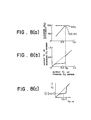
- An air/fuel ratio at which V r changes extremely great relative to a change of the output V has been found to be an air/fuel ratio capable of giving high cleaning efficiencies for the three components of HC, CO and NO x (i.e., the stoichiometric air/fuel ratio), irrespective of variations in characteristics from one 0 2 sensor to another, changes of the characteristics of each 0 2 sensor along the passage of time, and the like.
- the output characteristics of the forward O2 sensor 17 and rearward 0 2 sensor 18 are illustrated as shown in FIG. 8(b) for the following reasons.
- unburnt components such as CO are contained in an exhaust gas
- the output levels of the 0 2 sensors increase.
- the output of the forward 0 2 sensor 17 increases for the same reasons because unburnt gases such as HC, CO and H 2 exist on the upstream side of the catalytic converter 9.
- the output of the rearward 0 2 sensor 18 does not increase since such unburnt gases have been cleaned by the catalytic converter 9 on the downstream side of the catalytic converter 9 and also inside the catalytic converter 9. Since these relationship becomes very clear in the vicinity of the stoichiometric airifuel ratio, characteristics such as those depicted in FIG. 8(b) are obtained.
- the standard value changing means 48 is equipped with a characteristics computing means 49 which is adapted to compute the characteristics in relationship between the output of the forward 0 2 sensor 17 and that of the rearward 0 2 sensor 18.
- An output value V fc of the forward 0 2 sensor 17, which has been determined by the characte ristic computing means 49, is stored as a new rich/lean judgement voltage V fc . This function of renewal is provided with the rich/lean judgement voltage setting means 45.
- V f -V r characteristics and the standard value V fc for rich/lean judgement are stored in the BRUAM 33.
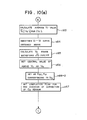
- FIGS. 4(a) through 4(e) illustrate a single flow chart
- the flow chart is very long and for the sake of convenience, has hence been divided at the appropriate parts into the five figures.
- Step a3 the routine is started firstly as depicted in FIG. 4(a) when a key switch (ignition switch) is turned on.
- the RAM 32 and interfaces are initialized in Step a1. It is next judged in Step a2 whether the battery 24 has been disconnected or not. Since the battery 24 is kept connected generally, the NO route is followed and a drive distance datum OD is inputted in Step a3
- Step a4 the OD datum is compared with a standard-color distance ODX which is backed up by the battery.
- operational state information is inputted in Step a5.
- Step a6 it is judged whether the operational state is in a fuel cut-off zone or not.
- a fuel cut-off flag is reset in Step a7, followed by setting of the correction factors K WT , K AT , K A p and K AC in Step a8.
- the dead time To is then set in Step a9. These factors are set by the cooling-water-temperature-dependent correction means 40, intake-air-temperature-dependent correction means 41, barometric-pressure-dependent correction means 42, accelerating fuel-increment correction means 43 and dead time correction means 44, respectively.
- Step a10 it it is next judged from the output voltage value of the forward 0 2 sensor 17 whether the sensor is in an active state or not.
- Step a12 a judgement is made to determine whether it is in the air/fuel ratio (A/F) feedback mode or not.
- A/F zone a prescribed operation zone which is determined by the load and revolutionary speed of the engine
- Step a13 it is judged in Step a13 whether a completion flag for the checking of the O 2 sensor correction has been set or not. Since Step a71 is usually jumped over, the completion flag has been set.
- the routine therefore advances along the YES route, and in Step a14, the output V f of the forward 0 2 sensor 17 and the rich/lean judgement voltage V fc are compared with each other.
- V fc >V f it is judged in Step a15 whether a without feedback flag (hereinafter called "WOFB flag”) has been set or not.
- WOFB flag a without feedback flag
- Flag L indicates enrichment by 1 and leanness by 2.
- leanness as used herein should be interpreted to mean that an air-fuel mixture is rendered leaner.
- Step a16-3 the feedback correction factor K FB is determined as 1 + P + I in Step a17 and this value K FB is inputted to an address K AF in Step a21.
- Step a24 The initial setting of a scan counter is then performed in Step a24.
- a suitable value other than 0 is chosen as an initial value at this time.
- the scan counter is also used upon changing and renewal of the standard value as will be described subsequently.
- Step a24 n sets of V f counters which will also be used at the same time as the scan counter are reset in advance.
- the cycle number SCOUNT which will also be used upon changing and renewal of the standard value as will also be described subsequently, is reduced to 0 in Step a25, and the routine then returns to Step a5 of FIG. 4(a).
- Step a16-4 it is judged whether Flag L is 1 or not.
- L is judged to be 1 in Step a16-3, the YES route is taken to perform the processing of Step a17.
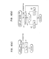
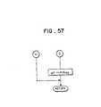
- the integration-time computing routine for the integral factor I can be illustrated like the flow chart of FIG. 6(b).
- Step d1 At every interruption of the timer, it is judged in Step d1 whether WOFB flag has been set or not.
- the feedback correction factor K FB is determined as 1 + P + I in Step a17. This value K FB is then inputted to the address K AF in Step a21. As a consequence, the feedback correction factor K FB is decreased by the proportional gain P RL for leanness from its maximum value.
- Step a24 the initial setting of the scan counter is performed in Step a24 and after reducing the cycle number SCOUNT to 0 in Step a25, the routine returns to Step a5 of FIG. 4(a).
- Step a17 When the routine has returned again to Step a19-1 via Step a18, the YES route is taken this time because L has been changed to 2 in Step a19-3. The processing of Step a17 is therefore applied.
- Step a14 When V fc becomes greater than V f (V fc >V f ) as a result of leanness in the above-described manner, the YES route is taken in Step a14, and it is judged in Step a15 whether WOFB flag has been set or not.
- WOFB flag When the operation is still in the A/F feedback mode, WOFB flag is still in the reset state.
- the feedback correction factor K FB is determined as 1 + P + I in Step a17. This value K FB is then inputted to the address K AF in Step a21. As a consequence, the feedback correction factor K FB is increased by the proportional gain P LR for enrichment from its minimum value.
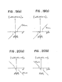
- the feedback correction factor K FB is varied as shown in FIG. 7(c) so that the desired air/fuel ratio control is performed in the A/F feedback mode.
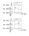
- FIG. 7(a) is a waveform diagram of the output of the forward 0 2 sensor
- FIG. 7(b) is a waveform diagram for the rich/lean judgement.
- Step a18 Since WOFB flag is in a set state at the time point immediately after the entering.
- the proportional gain P is changed to 0 in Step a19-4, WOFB flag is reset in Step a19-5, and Flag L is changed to 2 in Step a19-3.
- the feedback correction factor K FB is determined as 1 + P + I in Step a17 and this value K FB is inputted to the address K AF in Step a21.
- the comparator means 46 and correction factor determination means 47 in the 0 2 sensor feedback correction means 37 that perform the comparison between V fc and V f and determine the correction factor K AF on the basis of results of the comparison.
- Step a27 As shown in FIG. 4(a)
- the integral factor I is changed to 0 in Step a28 as depicted in FIG. 4(b)
- an initial value for example, 10 seconds or so
- the mapped A/F correction factor K AFM is inputted to the address K AF in Step a31, and after setting WOFB flag in Step a31-2, the routine returns to Step a5 via Steps a24 and a25. Since WOFB flag has been set in Step a31-2, WOFB flag is in a set state at the time point immediately after entering the A/F feedback mode.
- Step a10 or a12 When the answer is "NO" in Step a10 or a12, it is impossible to perform the A/F feedback control.
- the routine therefore returns to Step a5 via Steps a28, a31, a31-2, a24 and a25.
- each solenoid valve 8 is actuated to inject a desired quantity of the fuel. In this manner, the desired air/fuel ratio control is effected.
- the operation time of an engine can be typified by the drive distance where the engine is mounted on a vehicle. This may however be the time period of an actual operation.
- the term "drive distance” as used hereinafter may also mean "operation time”.
- Step a5 the routine advances through Step a5 and performs the processing of Step a6.
- the routine advances through Steps a7-a9 and the processings of Steps a10-a12 are performed.
- Step a13 the flag for the completion of checking of the O2 sensor has been set or not. Since it has been reset in Step a71 in this case, the routine advances through the NO route and then moves to Steps a11,a32,a33 illustrated in FIG. 4(c).
- Step a11 a judgement is made to determine whether the rearward 0 2 sensor is in an active state or not.
- Steps a32,a33 it is judged whether the revolutionary speed Ne of the engine is 3,000 rpm or lower and whether it is 1,500 rpm or higher. When both answers are "YES”, it is judged in Step a34 whether the engine fluctuation
- Step a37 When both answers are “YES”, it is judged in Step a37 whether the fluctuation
- the timer T KC is designed to operate at every time interruption in accordance with the timer subtraction routine shown in FIG. 6(a).
- the timer subtracts 1 from the contents of T KC to give new contents, in other words, performs a downcount.
- Step a32,a37 When the answers of Steps a32,a37 are both "NO", an initial value (the same value as that inputted in Step a29) is inputted to the timer T KC and the routine returns to the processings of Step a14 and its subsequent steps shown in FIG. 4(b).
- the routine does not therefore advance to the standard value rewriting processing and is caused to return to the side of the routine work for normal -driving so long as both O2 sensors 17,18 are not in an active state, the operation is not in the A/F feedback mode (in which the operation range is set in a relatively stable operation range), the revolutionary speed Ne of the engine does not fall between 1,500 and 3,000 (inclusive, i.e., 1,500 ⁇ Ne ⁇ 3,000), the engine fluctuation is large, the intake air quantity is little, or the intake air fluctuation or throttle opening rate fluctuation is great.
- the routine does not advance either to the standard value rewriting processing and is caused to return to the side of the routine work for normal driving until the lapse of prescribed period of time (a time period corresponding to the initial value of the timer T KC ) after the full satisfaction of the conditions.
- WOFB flag is set in Step a39-2 and in Step a49 of FIG. 4(d), it is judged whether the scan cycle counter is 0 or not. Since the initial value other than 0 has been set at the beginning in Step a24 of FIG. 4(b), the NO route is taken and in Step a50, it is judged whether the cycle number SCOUNT is 0 or not. In this case, the cycle number has been set at 0 in Step a25 shown in FIG. 4(b).
- Step a51 decrement (DCR) processing is applied so that the contents of the scan counter are decreased by 1.
- Flag COND is changed to 1 in the next Step a52 to judge the state of Flag COND in Step a53. Since COND is 1 in this case, the cycle number SCOUNT is increased by 1 step in Step a54.
- Step a56 the factor K AF is determined from K ⁇ to shift the air/fuel ratio to the rich side intentionally.
- Step a57 the output V f of the forward 0 2 sensor 17 and the output V r of the rearward 0 2 sensor are read in Step a57.
- Step a58 V r is added to the memory (RAM) which has been address-formatted by V f .
- Step a59 the number of data corresponding to the thus-added V f is increased by 1.
- an address number sufficient to prepare the V f -V r characteristic diagram shown in FIG. 8(b) is chosen as the address number of the memory.
- the inverse number of this address number is equivalent to the resolution.
- the V f counters are provided as many as the address number (n) of the memory, and when V r is stored at a corresponding address, the count number is increased by 1.
- Step a59 the routine returns to Step a5 of FIG. 4(a).
- the routine advances through the NO route in Step a6, the NO route in Step a13 of FIG. 4(b) and the YES route in Step a39 and returns again to Step a49 shown in FIG. 4(d), the NO route is taken because the scan cycle counter is still not 0.
- Step a50 a judgement is made to determine whether SCOUNT is 0 or not. Since SCOUNT has been set at 1 in Step a54 in this case, the NO route is taken in Step a50 and in Step a60, it is judged whether SCOUNT is 255 or not.
- Step a61 is jumped over and a judgement is made in Step a53 to determine the state of Flag COND. Since the state of COND which has been set at 1 in Step a52 has not been cancelled in this case, SCOUNT is again increased by 1 in Step a54. Accordingly, the factor K s is set by introducing 2/128 as the term SCOUNT/128 in Step a55. After the factor K AF is determined to shift the air/fuel ratio to the lean side a little, the individual outputs V f and V r of the forward 0 2 sensor 17 and rearward 0 2 sensor 18 are read, and V r is added to the memory which has been address-formatted by V f .
- Steps a56 and a59 After increment of a datum number corresponding to V f thus added (Steps a56 and a59), the routine returns to Step a5 of FIG. 4(a) and as in the foregoing, again to Step a49 of FIG. 4(d).
- Step a61 When SCOUNT reaches 255, the routine is switched to the YES route in Step a60 and Flag COND hence changes to 0 (Step a61).
- Step a62 is then performed subsequent to Step a53. Namely, the cycle number SCOUNT is decreased by 1 step.
- the output V f of the forward O 2 sensor 17 and the output V r of the rearward 0 2 sensor 18 are read in Step a57.
- V r is added to the memory (RAM) which has been address-formatted by V f .
- the datum number corresponding the thus-added V f is increased by 1. Since this is the second performance of the routine, the count number of the corresponding counter is increased to 2.
- Step a59 the routine returns to Step a5 of FIG. 4(a).
- the routine advances through the NO route in Step a6, the NO route in Step a13 of FIG. 4(b) and the YES route in Step a39 and returns again to Step a49 shown in FIG. 4(d), the NO route is taken because the scan cycle counter is still not 0.
- Step a50 a judgement is made to determine whether SCOUNT is 0 or not. Since SCOUNT has been set at 254 in Step a62 in this case, the NO route is taken in Step a50 and in Step a60, it is judged whether SCOUNT is 255 or not.
- Step a61 is jumped over and a judgement is made in Step a53 to determine the state of Flag COND. Since the state of COND which has been set at 0 in Step a61 has not been cancelled in this case, SCOUNT is again decreased by 1 in Step a62. Accordingly, the factor K s is set by introducing 253/128 as the term SCOUNT/128 in Step a55. After the factor K AF is determined, the individual outputs V,, V r of the forward 0 2 sensor 17 and rearward 0 2 sensor 18 are read, and V r is added to the memory which has been address-formatted by V f .
- Steps a56 and a59 After increment of a datum number corresponding to V f thus added (Steps a56 and a59), the routine returns to Step a5 of FIG. 4(a) and as in the foregoing, again to Step a49 of FIG. 4(d).
- Step a52 When SCOUNT reaches 0, the routine is switched to the YES route in Step a50. After decreasing the scan cycle counter by 1, Flag COND is changed to 1 (Step a52).
- the air/fuel ratio is shifted again from the rich side to the lean side and then in the opposite direction, thereby performing the third and fourth measurements of the Vf-V r characteristics.
- Step a63 an average value V r [(V f ) i ] of V r for (V f ) i measured by that time is calculated. Upon calculation of the average value, the count number of the V f counter is used.
- the V r -V f curve is smoothened by a suitable interpolation method or the like in Step a64.
- the characteristics thus obtained [see FIG. 8(c)] are the V r- V t characteristics shown in FIG. 8(b).
- Step a65 A V f range satisfying d V r /dV f >K, namely, a V f range where V r rises abruptly is determined.
- Step a66 the median of the V f range is chosen as the rich/lean-judging standard value V fc .
- This new value V fc is stored in the BURAM 33.
- the completion flag for the checking of correction of the 0 2 sensor is then set in Step a67.
- the drive distance datum OD is inputted in Step a68, and the next standard value rewriting distance ODX is set, for example, at ODX + 800 (miles) in Step a69.
- Step a5 of FIG. 4(a) If the operation is not in the fuel cut-off zone, the NO route is taken in Step a6 and Steps a7-a9 are then performed. If the answers of Steps a7-a9 are all "YES", it is judged in Step a13 of FIG. 4(b) whether the completion flag for the checking of correction of the 0 2 sensor has been set or not. Since this flag is in a set state in Step a67 of FIG. 4(e), the above-described routine work for normal driving, said routine work being defined by Step a14 and its subsequent steps, is performed.
- the air/fuel ratio control is performed on the basis of the rich/lean-judging standard value V fc renewed in the manner described above.
- the rich/lean-judging standard value V fc to be compared with the output V f of the forward O2 sensor 17 can be changed and renewed on the basis of both outputs V f ,V r of the forward 0 2 sensor 17 and rearward 0 2 sensor 18, the accuracy of the control does not vary even by variations in characteristics from one 0 2 sensor to another and variations of the characteristics of each 0 2 sensor along the passage of time and more over, the cleaning efficiency of exhaust gas by the catalytic converter 9 is maintained high. High control reliability can thus be assured.
- the voltage V fc for rich/lean judgement is stored in the BURAM 33 and the stored value is not erased by the turn-off of the ignition switch 26 alone.
- the contents of the memory are erased.
- a representative V f value (for example, a value corresponding to 0.6 volt) is tentatively inputted as an intial value in Step a70. Thereafter, the resetting of the completion flag for the checking of correction of the 0 2 sensor is performed in Step a71.
- the air/fuel ratio is changed around the stoichiometric air/fuel ratio so that V f and V r are measured at a prescribed interval for a predetermined time period at each air/fuel ratio and their average values are calculated to obtain the graph of FIG. 8(c).
- the air/fuel ratio may vary and different V f -V r characteristics may exist in some instances, for example, upon feedback control of an actual system, the air/fuel ratio may be changed 1/128 by 1/128 from 125/128 of the K s value to 131/128 of the K s value while giving air/fuel ratio fluctuation similar to that observed on the actual system (for example, air / fuel ratio variation cycle: 2 Hz; air/fuel ratio fluctuation magnitude: 5% in terms of fuel).
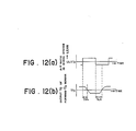
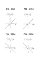
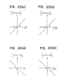
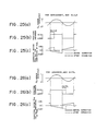
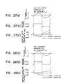
- the air/fuel ratio control system determines the response time ⁇ RL of the former 0 2 sensor 17 to the change from a rich air-fuel mixture to a lean air-fuel mixture and the response time ⁇ LR of the former O 2 sensor 17 to the change from a lean air-fuel mixture to a rich air-fuel mixture and in accordance with these response times ⁇ RL , ⁇ LR , corrects any one of the delay times DLYRL,DLYLR shown in FIG. 11, the proportional gains P RL ,P LR of the air/fuel ratio feedback control and the integral gains I RL ,I LR of tHe air/fuel ratio feedback control.
- the response time TRL is a judgement delay time of the forward O2 sensor 17 for a change from a rich air-fuel mixture to a lean air-fuel mixture and means the time -required until the output V f of the forward 0 2 sensor reaches the standard value V fc after the air/fuel ratio in the intake system has varied across (A/F) c from the rich side to the lean side.
- the response time ⁇ RL is a judgement delay time of the forward 0 2 sensor 17 for a change from a lean air- fuel mixture to a rich air-fuel mixture and means the time required until the output V f of the forward O 2 sensor reaches the standard value V fc after the air/fuel ratio has varied across (A/F) c from the lean side to the rich side [see FIGS. 12(a) and 12(b)].
- the second embodiment also compares the output V f from the forward O 2 sensor 17 with the predetermined standard value V fc (an intermediate value between the high-level output of the forward 0 2 sensor 17 and the low-level output thereof being chosen as the standard value V fc and said standard value V fc serving as a so-called rich/lean judgement voltage) and renders the air- fuel mixture richer when V fc >V f but makes it leaner when V fc ⁇ V f .
- V fc an intermediate value between the high-level output of the forward 0 2 sensor 17 and the low-level output thereof being chosen as the standard value V fc and said standard value V fc serving as a so-called rich/lean judgement voltage
- the 0 2 sensor feedback correction means 37 has, as depicted in FIG. 9, the rich/lean judgement voltage setting means 45 for setting the standard value V fc , the comparator means 46 for comparing the output V f from the forward 0 2 sensor 17 with the standard value V fc from the rich/lean judgement voltage setting means 45, and the correction factor determination means 47 for determining the air/fuel ratio correction factor K AF in accordance with comparison results from the comparator means 46.
- the present air/fuei ratio control system is also equipped with the standard value changing means 48 for allowing to change the standard value (rich/lean judgement voltage) V fc on the basis of the outputs V f and V r from the forward O2 sensor 17 and rearward 0 2 sensor 18, for example, for every predetermined drive distance.
- the standard value changing means 48 for allowing to change the standard value (rich/lean judgement voltage) V fc on the basis of the outputs V f and V r from the forward O2 sensor 17 and rearward 0 2 sensor 18, for example, for every predetermined drive distance.
- the correction factor determination means 47 includes a means for determining response times ⁇ RL , ⁇ LR and correcting any one of the response delay times DLYRL,DLYLR, proportional gains P RL ,P LR and integral gains I RL ,I LR in accordance with these response times TRL , TLR .
- V f -V r characteristics, V f -K o characteristics, and the response delay times DLYRL,DLYLR, proportional gains P RL ,P LR and integral gains I RL ,I LR to be corrected in accordance with the rich/lean-judging standard voltage V fc or response times ⁇ RL , ⁇ LR are stored in the BURAM 33.
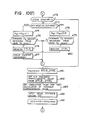
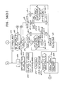
- FIGS. 10(a) through 10(f) illustrate a single flow chart
- the flow chart is very long and for the sake of convenience, has hence been divided at the appropriate parts into the six figures.
- Step a2 the routine is also started firstly as depicted in FIG. 10(a) when the key switch (ignition switch) is turned on.
- Step a2 the RAM 32 and interfaces are initialized in Step a1. It is next judged in Step a2 whether the battery 24 has been disconnected or not. Since the battery 24 is kept connected generally, the NO route is followed and a drive distance datum OD is inputted in Step a3.
- Step a4 the OD datum is compared with the standard-color distance ODX which is backed up by the battery.
- operational state information is inputted in Step a5.
- Step a6 it is judged whether the operational state is in a fuel cut-off zone or not.
- the fuel cut-off flag is reset in Step a7, followed by setting of the correction factors K WT , K AT , K AP and K AC in Step a8.
- the dead time T ⁇ is then set in Step a9. These factors are set by the cooling-water- temperature-dependent correction means 40, intake-air-temperature-dependent correction means 41, barometric-pressure-dependent correction means 42, accelerating fuel-increment correction means 43 and dead time correction means 44, respectively.
- Step a10 it is next judged from the output voltage value of the forward 0 2 sensor 17 whether the sensor is in an active state or not.
- Step a12 a judgement is made to determine whether it is in the air/fuel ratio (A/F) feedback mode or not.
- Step a13 If the operation is in the A/F feedback mode, it is judged in Step a13 whether a completion flag for the calculation of a feedback characteristic value (FB characteristic value) has been set or not. Since the FB characteristic value is usually in a set state, the YES route is taken, and in Step a14, the output V f of the forward 0 2 sensor 17 and the rich/lean judgement voltage V fc are compared with each other. When V fc >V f , it is judged in Step a15 whether WOFB flag has been set or not.
- FB characteristic value feedback characteristic value
- Step a16-3 the feedback correction factor K FB is determined as 1 + P + I in Step a17 and this value K FB is inputted to an address K AF in Step a21.
- Step a22 It is thereafter judged in Step a22 whether the K c count initiation flag has been set or not. Since the flag is in a reset state at the beginning, the routine jumps to Step a23-2 to judge whether the completion flag for the checking of the 0 2 sensor has been set or not. Since the flag is generally in a set state, the YES route is taken so that the routine returns to Step a5 of FIG. 10(a).
- Step a16-4 If Flag L is 1 or not. Since Flag L has been changed to 1 in this case in Step a16-3, the YES route is taken to perform the processing of Step a17.
- the integration-time computing routine for the integral factor I is the same as the flow chart of FIG. 6(b) in the first embodiment described above.
- Step a17 When the routine has returned again to Step a19-1 via Step a18, the YES route is taken this time because L has been changed to 2 in Step a19-3. The processing of Step a17 is therefore applied.
- Step a14 When V fc becomes greater than V f (V fc >V f ) as a result of leanness in the above-described manner, the YES route is taken in Step a14, and it is judged in Step a15 whether WOFB flag has been set or not.
- WOFB flag When the operation is still in the A/F feedback mode, WOFB flag is still in the reset state.
- Step a17 While the delay time DLYRL has not lapsed, the NO route is taken to perform the processing of Step a17. After the delay time DLYRL has lapsed, the YES route is taken and the proportional gain P LR for enrichment is added to the proportional gain P in Step a16-5 so as to use the sum as P.
- the feedback correction factor K FB is determined as 1 + P + I in Step a17. This value K FB is then inputted to the address K AF in Step a21. As a consequence, the feedback correction factor K FB is increased by the proportional gain P LR for enrichment from its minimum value.
- the feedback correction factor K FB is varied as shown in FIG. 11 (c) so that the desired air/fuel ratio control is performed in the A/F feedback mode.
- FIG. 11 (a) is a waveform diagram of the output of the forward 0 2 sensor
- FIG. 11 (b) is a waveform diagram for the rich/lean judgement.
- the delay times DLYRL,DLYLR are, as illustrated in FIG. 11(b), times corresponding to the delays until a rich/lean judgment is performed when the output of the 0 2 sensor has crossed the rich/lean judgement voltage V fc upwardly or downwardly as illustrated in FIG. 11 (a).
- Step a18 since WOFB flag is in a set state at the time point immediately after the entering, the proportional gain P is changed to 0 in Step a19-4, WOFB flag is reset in Step a19-5, and Flag L is changed to 2 in Step a19-3.
- the feedback correction factor K FB is determined as 1 + P + I in Step a17 and this value K FB is inputted to the address K AF in Step a21.
- the comparator means 46 and correction factor determination means 47 in the O 2 sensor feedback correction means 37 that perform the comparison between V fc and V f and determine the correction factor K AF on the basis of results of the comparison.
- the delay times DLYRL, DLYLR, proportional gains P RL ,P LR and integral gains I RL ,I LR are variable as will be described subsequently.
- Step a6 When the operation is found to be in the fuel cut-off zone in Step a6 subsequent to Step a5, the fuel cut-off flag is set in Step a27 as shown in FIG. 10(a), the integral factor I is changed to 0 in Step a28 as depicted in FIG. 10(b), an initial value (for example, 10 seconds or so) is inputted to the timer T KC in Step a29, and the mapped A/F correction factor K AFM is set in accordance with the load and revolutionary speed of the engine.
- the mapped A/F correction factor K AFM is inputted to the address K AF in Step a31, and after setting WOFB flag in Step a31-2, the routine returns to Step a5 via Steps a23-2.
- Step a10 or a12 When the answer is "NO" in Step a10 or a12, it is impossible to perform the A/F feedback control.
- the routine therefore returns to Step a5 via Steps a28, a31, a31-2 and a23-2.
- each solenoid valve 8 is actuated to inject a desired quantity of the fuel. In this manner, the desired air/fuel ratio control is effected.
- Step A4 When the drive distance OD reaches the standard value rewriting distance ODX, the YES route is taken in Step A4 and the flag for the completion of checking of the 0 2 sensor is reset in Step a71 and the completion flag for the completion of calculation of the FB characteristic values is reset in Step a71-2.
- Step a5 the routine advances through Step a5 and performs the processing of Step a6.
- the routine advances through Steps a7-a9 and the processings of Steps a10-a12 are performed.
- Step a13' the flag for the calculation of the FB characteristic values has been set or not. Since it has been reset in Step a71-2 in this case, the routine advances through the NO route and then moves to Steps a11,a32,a33 illustrated in FIG. 10(c).
- Step a11 a judgement is made to determine whether the rearward O 2 sensor is in an active state or not.
- Steps a32,a33 it is judged whether the revolutionary speed Ne of the engine is 3,000 rpm or lower and whether it is 1,500 rpm or higher. When both answers are "YES”, it is judged in Step a34 whether the engine fluctuation
- Step a37 When both answers are “YES”, it is judged in Step a37 whether the fluctuation
- timer T KC is also designed to operate at every time interruption in accordance with the timer subtraction routine shown in FIG. 6-(a).
- Step a40 the Kc count initiation flag is reset in Step a40, and the factor K c (this factor K c is a value which would probably become equal to the stoichiometric air/fuel ratio when the A/F feedback control is performed, and like the above-described first embodiment, indicates a median) is set at 1 in Step a41.
- the routine After setting an initial value other than 0 in Step a41-2, the routine returns to the processings of Step a14 and its subsequent steps depicted in FIG. 10(b).
- Step a23-2 the routine advances through the NO route because the completion flag for the checking of correction of the 0 2 sensor has been reset.
- Initial setting of the scan counter is then performed in Step a24.
- a suitable number other than 0 is selected as the initial value.
- the scan counter is used upon changing and renewing the standard value.
- the n sets of V f counters, which are employed at the this time, are also reset in Step a24.
- Step a25 the cycle number SCOUNT which is also used upon changing and renewing the standard value is set at 0 in Step a25. After resetting the K r count completion flag in Step a26, the routine returns to Step a5.
- the resetting of the V f counters may be performed in Step a41-2.
- Step a32-a37 When the answers of Steps a32-a37 are both "NO", an initial value (the same value as that inputted in Step a29) is inputted to the timer T KC and the K c count initiation flag is set in Step a40. After changing the factor K c to 1 in Step a41, an initial value is set in the cycle counter. The routine then returns to the processings of Step a14 and its subsequent steps shown in FIG. 10(b).
- the routine does not therefore advance to the standard value rewriting processing and is caused to return to the side of the routine work for normal driving so long as both 0 2 sensors 17,18 are not in an active state, the operation is not in the A/F feedback mode (in which the operation range is set in a relatively stable operation range), the revolutionary speed Ne of the engine does not fall between 1,500 and 3,000 (inclusive, i.e., 1,500 ⁇ Ne ⁇ 3,000), the engine fluctuation is large, the intake air quantity is little, or the intake air fluctuation or throttle opening rate fluctuation is great.
- the routine does not advance either to the standard value rewriting processing and is caused to return to the side of the routine work for normal driving until the lapse of a prescribed period of time (a time period corresponding to the initial value of the timer T KC ) after the full satisfaction of the conditions.
- Step a42' of FIG. 10(c) it is judged in Step a42' of FIG. 10(c) whether the completion flag for the checking of correction of the 0 2 sensor has been set or not. Since this flag has been reset in Step a71 in this case, the routine advances through the NO route to Step a42, where it is judged whether the K c count completion flag has been set or not.
- Step a43 Since the K c count completion flag has been reset in Step a26 [see FIG. 10(b)], the NO route is taken first of all. It is then judged in Step a43 whether the K c count initiation flag has been set or not. Since the K c count initiation flag is in a reset state at the beginning, the NO route is taken to judge whether the factor K FB is the maximum value K FB (EXT) or not. If the factor K FB is found to be the maximum value K Fs (EXT), the K c count initiation flag is set in Step a45 so that the processings of Step a14 and its subsequent steps of FIG. 10(b) are applied.
- Step a22 After performing the processings of Steps a15-a21, it is judged in Step a22 whether the K c count initiation flag has been set or not. Since the K c count initiation flag has been set in Step a45 of FIG. 10(c), the YES route is taken in this Step a22. In the next Step a23, K c (the value which would probably become equal to the stoichiometric air/fuel ratio when the A/F feedback control is performed; median) is determined as kK c + (1-k)(K FB - 1). Thereafter, the routine returns to Steps a23-2,a24-26,a5 so as to perform their respective processings.
- Step a23 is jumped over and the routine returns to Steps a23-2,a24-a26,a5 so as to perform their respective processings.
- the median K c is not changed and renewed.
- Step 46 When the routine advances again to Step a43 in the same manner, the YES route is taken since the K c count initiation flag has been set in Step a45. It is then judged in Step 46 whether the maximum value K FB (EXT) has occurred four times after the detection of the first occurrence of the maximum value of the factor K FS .
- Step a46 While the maximum value K FB (EXT) has not occurred four times, the NO route is taken in Step a46.
- the routine then advances through Steps a14-a21 to Step a22, where the YES route is taken to change and renew the median K c . Thereafter, the processings of Steps a23-2,a24 and their subsequent processings are performed.
- the median K c is set tentatively at 1.
- Step a42 When the pre-processing for the rewriting of the standard value has been completed in the above manner, the YES route is taken in Step a42. After setting WOFB flag in Step a42-2, it is judged in Step a49 of FIG. 10(d) whether the scan cycle counter is 0 or not. Since the initial value other than 0 has been set at the beginning in Step a24 of FIG. 10(b), the NO route is taken and in Step a50, it is judged whether the cycle number SCOUNT is 0 or not. In this case, the cycle number has been set at 0 in Step a25 shown in FIG. 10(b).
- Step a51 decrement (DCR) processing is applied so that the contents of the scan counter are decreased by 1.
- Flag COND is changed to 1 in the next Step a52 to judge the state of Flag COND in Step a53. Since COND is 1 in this case, the cycle number SCOUNT is increased by 1 step in Step a54.
- Step a56 the factor K o is determined from K S x K c (in this case, K c is a value of 1 or substantially 1). Further, K AF is set at K o in Step a56" to shift the airifuel ratio to the rich side intentionally. Thereafter, the output V f of the forward 0 2 sensor 17 and the output V r of the rearward 0 2 sensor are read in Step a57. In Step a58, V r is added to the memory (RAM) which has been address-formatted by V f .
- RAM memory
- Step a58-2 K o is also added to the memory (RAM) which has been address-formatted by V f .
- the number of data corresponding to the thus-added V f is increased by 1.
- an address number sufficient to prepare the V f -V r characteristic diagram described before in the first embodiment and shown in FIG. 8(b) is chosen as the address number of the memory.
- the inverse number of this address number is equivalent to the resolution.
- the V f counters are provided as many as the address number (n) of the memory, and when V r is stored at a corresponding address, the count number is increased by 1.
- the second embodiment is equal to the first embodiment described before.
- V f counters may be used commonly not only as the memory for V r (see the processing of Step a58) but also as the memory for K o (see the processing of Step a58-2).
- their own V f counters may also be used.
- Step a59 the routine returns to Step a5 of FIG. 10(a).
- the routine advances through the NO route in Step a13, the YES route is taken in Step a42 and the routine then advances again to Step a49 shown in FIG. 10(d). Since the scan counter is still not 0, the NO route is taken to judge in Step a50 whether SCOUNT is 0 or not. Since SCOUNT has been set at 1 in Step a54 in this case, the NO route is taken in Step a50 and in Step a60, it is judged whether SCOUNT is 255 or not. Since the answer is "NO" in this case, Step a61 is jumped over and a judgement is made in Step a53 to determine the state of Flag COND.
- Step a54 Since the state of COND which has been set at 1 in Step a52 has not been cancelled in this case, SCOUNT is again increased by 1 in Step a54. Accordingly, the factor K s is set by introducing 2/128 as the term SCOUNT/128 in Step a55.
- the individual outputs V f and V r of the forward 0 2 sensor 17 and rearward O 2 sensor 18 are read, and V r and K o are added to the memory which has been address-formatted by V f .
- Step a56 and a59 After increment of a datum number corresponding to V f thus added (Steps a56 and a59), the routine returns to Step a5 of FIG. 10(a) and as in the foregoing, again to Step a49 of FIG. 10(d).
- Step a61 When SCOUNT reaches 255, the routine is switched to the YES route in Step a60 and Flag COND hence changes to 0 (Step a61).
- Step a62 is then performed subsequent to Step a53. Namely, the cycle number SCOUNT is decreased by 1 step.
- the output V f of the forward 0 2 sensor 17 and the output V r of the rearward O 2 sensor 18 are read in Step a57.
- V r and K o are added to the memory (RAM) which has been address-formatted by V f .
- the datum number corresponding the thus-added V f is increased by 1 in Step a59. Since this is the second performance of the routine, the count number of the corresponding counter is increased to 2.
- Step a59 the routine returns to Step a5 of FIG. 10(a).
- the routine advances through the NO route in Step a6, the NO route in Step a13 and the YES route in Step a42 and returns again to Step a49 shown in FIG. 10(d), the NO route is taken because the scan cycle counter is still not 0.
- Step a50 a judgement is made to determine whether SCOUNT is 0 or not. Since SCOUNT has been set at 254 in Step a62 in this case, the NO route is taken in Step a50 and in Step a60, it is judged whether SCOUNT is 255 or not.
- Step a61 is jumped over and a judgement is made in Step a53 to determine the state of Flag COND. Since the state of COND which has been set at 0 in Step a61 has not been cancelled in this case, SCOUNT is again decreased by 1 in Step a62. Accordingly, the factor K s is set by introducing 253/128 as the term SCOUNT/128 in Step a55. After the factors K o and K AF are determined, the individual outputs V f , V r of the forward 0 2 sensor 17 and rearward 0 2 sensor 18 are read, and V r and K o are added to the memory which has been address-formatted by V f .
- Steps a56 and a59 After increment of a datum number corresponding to V f thus added (Steps a56 and a59), the routine returns to Step a5 of FIG. 10(a) and as in the foregoing, again to Step a49 of FIG. 10(d).
- Step a52 When SCOUNT reaches 0, the routine is switched to the YES route in Step a50. After decreasing the scan cycle counter by 1, Flag COND is changed to 1 (Step a52).
- the air/fuel ratio is shifted again from the rich side to the lean side and then in the opposite direction, thereby performing the third and fourth measurements of the V f -V r characteristics and V f -K o characteristics.
- Step a63 an average value V r [(V f ) i ] of V r for (V f ) i measured by that time is calculated. Upon calculation of the average value, the count number of the V f counter is used.
- the V r -V f curve is smoothened by a suitable interpolation method or the like in Step a64.
- the characteristics thus obtained [see FIG. 8(c) of the first embodiment] are the V r- V f characteristics shown in FIG. 8(b) of the first embodiment.
- Step a65 A V f range satisfying d V r /dV f >K, namely, a V f range where V r rises abruptly is determined.
- Step a66 the median of the V f range is chosen as the rich/lean-judging standard value V fc .
- This new value V fc is stored in the BURAM 33.
- Step 255-2 K o corresponding to the V fc is set as K oc , and the completion flag for the checking of correction of the 0 2 sensor is set in Step a67.
- Step a6 If the operation is not in the fuel cut-off zone, the NO route is taken in Step a6 and the processings of Steps a7-ag are then performed. If the answers of Steps a7-ag are all "YES", it is judged in Step a13 whether the completion flag for the calculation of the FB characteristic values has been set or not. Since this flag is in a reset state in Step a71-2, the NO route is again taken in Step a13'. If the standard value rewriting conditions are satisfied, it is judged in Step a42 whether the completion flag for the checking of the O 2 sensor has been set or not.
- the flag has already been set subsequent to the renewal of the standard value in Step a67 of FIG. 10(e).
- the routine hence advances through the YES route to Step a72 of FIG. 10(f), where a judgement is made to determine whether the cycle counter is 0 or not. Since the initial value other than 0 has been set in this case in Step a41-2 of FIG. 10(c), the NO route is taken and in Step a73, it is judged whether the operation is in the rich mode or in the lean mode.
- the factor K AF is set as K oc x 1.1 in Step a74 and in Step a75, it is judged whether the output of the forward 0 2 sensor 17 has been reversed from the lean level to the rich level.
- Step 76 the value DTLR corresponding to the response time ⁇ LR from the lean level to the rich level of the output of the forward 0 2 sensor 17 is measured in Step 76.
- the contents of the cycle counter are decreased by 1 in Step a77, and the routine returns to Step a5 of FIG. 10(a).
- the measurement of DTLR is carried out by measuring the time until the output of the forward 0 2 sensor 17 is reversed from the lean level to the rich level after an injection command is sent to the solenoid valve 8.
- This may be practised, for example, in the following manner.
- the DTLR measuring counter is always maintained in a reset state until the injection command is produced and after the production of the injection command, the counter is caused to perform counting either upwardly or downwardly and the output of the forward 0 2 sensor 17 is reversed from the lean level to the rich level, the above counting is stopped and the value at this time is latched as DTLR.
- Step a80 the value DTRL corresponding to the response time TRL from the rich level to the lean level of the output of the forward O 2 sensor 17 is measured in Step a80.
- the contents of the cycle counter are decreased by 1 in Step a77, and the routine returns to Step a5 of FIG. 10(a).
- the measurement of DTRL is also carried out by measuring the time until the output of the forward O 2 sensor 17 is reversed from the rich level to the lean level after an injection command is sent to the solenoid valve 8.
- the DTRL measuring counter is always maintained in a reset state until the injection command is produced. After the production of the injection command, the counter is caused to perform counting either upwardly or downwardly. The counting is stopped when the output of the forward O 2 sensor 17 is reversed from the rich level to the lean level. The value at this time is latched as DTRL.
- response times ⁇ RL , ⁇ LR of the forward 0 2 sensor 17 have been determined in the above manner.
- response times ⁇ RL , ⁇ LR can be determined by giving a periodic air/fuel ratio mode such as that shown in FIGS. 12(a) and 12(b) while the air/fuel feedback is maintained as an open loop under such a load as that employed upon determination of the V f -V r characteristics shown in FIG. 8(b).
- the median (A/F) c of the air/fuel ratio variation mode shown in FIG. 12(a) corresponds to the median K c which gives V fc .
- the median K c of the correction factor is shifted to the lean side or rich side when TLR * TRL .
- any one of the response delay times DLYRL,DLYLR, proportional gains P RL ,P LR and integral gains I RL ,I LR is corrected. The thus-corrected value is then stored in the memory.
- Step a83 the completion flag for the calculation of the delay time is set in Step a83, the drive distance datum OD is inputted in Step a68, and the next standard value rewriting distance ODX is set for example at ODX + 800 miles in Step a69.
- the routine thereafter returns to Step a5.
- Step a6 After the routine has returned to Step a5 of FIG. 10(a), the NO route is taken in Step a6 unless the operation is in the fuel cut-off zone. Subsequent to the processings of Steps a7-a9, if the answers of Steps a10-a12 are all "YES", it is judged in Step a13' whether the completion flag for the calculation of the FE characteristic values has been set or not. Since the flag has been set in Step a83 of FIG. 10(f), the above-described routine work for normal driving, said work being defined by Step a14 and its subsequent steps, is performed.
- the air/fuel ratio control is performed on the basis of the rich/lean-judging standard value V fc renewed as described above and if necessary, in accordance with the characteristic values (DLYRL, DLYLR, P RL , P LR , I RL , I LR ) for the airifuel ratio feedback control, which values have been corrected based on the response times ⁇ RL , ⁇ LR .
- the rich/lean-judging standard value V fc to be compared with the output V f of the forward O 2 sensor 17 can be changed and renewed on the basis of both outputs V f ,V r of the forward 0 2 sensor 17 and rearward 0 2 sensor 18 and moreover, the characteristic values for the airifuel ratio feedback control are corrected in accordance with the response time of the forward 0 2 sensor 17, the accuracy of the control does not vary even by variations in characteristics from one 0 2 sensor to another and variations of the characteristics of each 0 2 sensor along the passage of time and more over, the cleaning efficiency of exhaust gas by the catalytic converter 9 is maintained high. High control reliability can thus be assured like the first embodiment described before.
- the system of the first embodiment can exhibit particularly great effects when the response times ⁇ RL , ⁇ LR are substantially equal to each other (
- the rich/lean judgement voltage V fc and the characteristic values (DLYRL, DLYLR, P RL , P LR , I RL , I LR ) for the airifuel ratio feedback control, said values being subjected to corrections, are stored stored in the BURAM 33 and the stored values are not erased by the turn-off of the ignition switch 26 alone. However, the contents of the memory are erased when the battery 24 is disconnected. When the battery 24 is found to have a history of disconnection in Step a2 of FIG.
- V f value for example, values of DLYRL, DLYLR, P RL , P LR , I RL , I LR
- V f value for example, values of DLYRL, DLYLR, P RL , P LR , I RL , I LR
- the NO route is taken in Step a13' of FIG. 10(b), and after the standard value rewriting conditions are satisfied and the standard value rewriting pre-processing is performed, the rich/lean-judging standard value V fc is rewritten and the response times ⁇ RL , ⁇ LR are also determined.
- One or more of the characteristic val- ues ( DLYRL , DLYLR , P RL , P LR , I RL , I LR ) for the air/fuel ratio feedback control are hence corrected on the basis of these response times.
- the processing in this case is exactly the same as the processing upon the above-described rewriting of the standard value and the aforementioned correction of characteristic values for the airifuel ratio feedback control. Its detailed description is therefore omitted herein.
- the output V r of the rearward 0 2 sensor 18 is measured during the air/fuel ratio feedback control and one or more of the response delay times DLYRL,DLYLR, proportional gains P RL ,P LR and the integral gains I RL ,I LR are corrected on the basis of the output V r .
- the third embodiment also compares the output V t from the forward 0 2 sensor 17 with the predetermined standard value V fc (an intermediate value between the high-level output of the forward 0 2 sensor 17 and the low-level output thereof being chosen as the standard value V fc and said standard value V fc serving as a so-called rich/lean judgement voltage) and renders the air- fuel mixture richer when V fc >V f but makes it leaner when V fc ⁇ V f .
- V fc an intermediate value between the high-level output of the forward 0 2 sensor 17 and the low-level output thereof being chosen as the standard value V fc and said standard value V fc serving as a so-called rich/lean judgement voltage
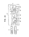
- the O2 sensor feedback correction means 37 has, as depicted in FIG. 13, the richilean judgement voltage setting means 45 for setting the standard value V fc , the comparator means 46 for comparing the output V f from the forward O2 sensor 17 with the standard value V fc from the richilean judgement voltage setting means 45, and a correction factor determination means 47 for determining the air/fuel ratio correction factor K AF in accordance with comparison results from the comparator means 46.
- the present air/fuel ratio control system is also equipped with the standard value changing means 48 for allowing to change the standard value (richilean judgement voltage) V fc on the basis of the outputs V f and V r from the forward 0 2 sensor 17 and rearward 0 2 sensor 18, for example, for every predetermined drive distance.
- the standard value changing means 48 for allowing to change the standard value (richilean judgement voltage) V fc on the basis of the outputs V f and V r from the forward 0 2 sensor 17 and rearward 0 2 sensor 18, for example, for every predetermined drive distance.
- the correction factor determination means 47 includes a means correcting any of the response delay times DLYRL,DLYLR, proportional gains P RL ,P LR and integral gains I RL ,I LR on the basis of the output V r of the rearward 0 2 sensor 18 measured during the air/fuel ratio feedback control.
- V f -V r characteristics and the response delay times DLYRL,DLYLR, proportional gains P RL ,P LR and integral gains I RL ,I LR corrected in accordance with the standard values V fc ,V rc or the output V r of the rearward 0 2 sensor 18 are stored in the BURAM 33.
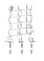
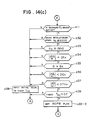
- FIGS. 14(a) through 14(e) The main routine for changing and renewing the rich/lean-judging standard value V fc for every predetermined drive distance or after every history of battery disconnection may be illustrated as shown in FIGS. 14(a) through 14(e). Since these flow charts are substantially the same as those depicted in FIGS. 4(a) through 4(e), the same processings as those in FIGS. 4(a) through 4(e) are identified by like step numbers and their description is omitted herein. Incidentally, the standard value rewriting distance DOX is backed up by the battery. In FIGS. 14(a) through 14(e), steps different from those shown in FIGS. 4(a) through 4(e) are Steps a70", a16-4', a19-1' and a23-2 in FIGS. 14(a) and 14(b) and Step a66' in FIG. 14(e).
- Step a70 initial values are inputted with respect to the standard value V rc of the output of the rearward 0 2 sensor, besides V fc - (those to be corrected on the basis of the output of the rearward O 2 sensor out of (DLYRL,DLYLR), (I RL ,I LR ) and (P RL ,P LR )).
- the standard value V rc is determined in the following manner. As illustrated in FIG. 31, the output value of the rearward O 2 sensor 18 corresponding substantially to the central point of a range in which d/V r /dV f is greater than a certain inclination [see FIG. 14(e), Step a65] is determined as the standard value V rc .
- V fc is about 0.6 volt by way of example, V rc is about 0.4 volt.
- V rc is set at a point ⁇ in FIG. 31, the cleaning efficiency of CO is deteriorated. If V rc is set at a point on the contrary, the cleaning efficiency of NO x is impaired. V rc is therefore set at the central point ⁇ as described above.
- Step a66' the median of the V f range determined in Step a65 is set as V fc and in addition, V r corresponding to this V fc is set as V rc .
- This V rc is the output value V r of the rearward 0 2 sensor 18, which corresponds to the point y described above.
- the standard value V rc of the output of the rearward 0 2 sensor (said V rc being available from V fc as mentioned above) is also renewed for the prescribed drive distance or at every history of battery disconnection in the third embodiment, in addition to the rich/lean-judging standard value V fc which is to be compared with the output V f of the forward 0 2 sensor 17.
- these these values V fc ,V rc are not set as fixed values but are set as variable values.
- Step a23-2 is similar to its corresponding step described in the second embodiment.
- Steps a16-4 and 19-1 are also similar to their corresponding ones described in the second embodiment, In both steps, it is judged after the attainment of V fc >V f whether the delay time DLYRL has lapsed or not and after the attainment of V fc ⁇ V f whether the delay time DLYLR has lapsed or not.
- DLYRL and DLYLR are however determined in a manner different from those in the second embodiment.
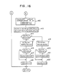
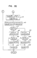
- the outputs 102SNS (V f ) and 102CCR (V r ) of the forward and rearward 0 2 sensors 17,18 are read in first of all in Step e1. As the timing of their reading, they may be read in, for example, every 5 msec or every 10 msec. In Step e2, it is then judged from the output voltage values of the forward and rearward 0 2 sensors 17,18 whether they are in an active state or not.
- Step e3 If both 0 2 sensors 17,18 are in the active state, it is judged in Step e3 whether the operation is in the air/fuel ratio feedback or not. If the answer is "YES”, the routine advances to Step e4 where a judgement is made to determined whether a predetermined period of time has lapsed after the entering in the air/fuel ratio feedback mode. If the answer is "YES”, it is judged in Step e5 whether the output frequency lAIR of the airflow sensor 11, namely, the intake air quantity is greater than a preset value.
- the preset value two values are set, one being a first preset value (XAFSFH) and the other a second preset value (XAFSFL).
- XAFSFH first preset value
- XAFSFL second preset value
- Step e5 In an operational state featuring a small intake air quantity (during idling or the like), the response of the 0 2 sensors is slow and the output characteristics of the 0 2 sensors are different. A judgement such as that performed in Step e5 is therefore carried out. It is also feasible to perform the following correction separately when the output frequency of the airflow sensor is lower than a preset value. In this case, learning is performed twice.
- Step e6 If the answer is "YES” in Step e5, it is judged in the next Step e6 whether the output of the forward 0 2 sensor has been reversed or not.
- V lc determined and renewed in the above-described main routine [FIGS. 4(a) through 4(e)] is used as the rich/lean-judging standard value V lc for each output of the forward 0 2 sensor 17.
- Step e6 the average output value of the rearward 0 2 sensor is renewed on the basis of the short-term output value 102CCR of the rearward 0 2 sensor at the time of reversal of the output of the forward O2 sensor and the average output value of the rearward 0 2 already in storage.
- 02RAVE in the right-hand member of the above formula indicates the last datum of the average output value of the rearward 0 2 sensor, which had replaced the previous one in Step e7 of the last performance of the time interruption routine and has been stored in the RAM.
- K1 is a factor set as a datum in the ROM.
- the contents of the counter COUNT are reduced by 1 in Step e8.
- the initial value of the counter is set by the data of the ROM and a desired value from 1 to 255 may be set by way of example. This initial value was set in the counter in Step a1 of the main routine shown in FIG. 14(a), when the key switch was turned on.
- Step e9 it is judged whether the number of the counter has been counted down to 0. If the answer is "NO”, the routine returns.
- the routine advances to Step e11 where from a target output voltage value 02RTRG (which corresponds to V rc ) of the rearward O2 sensor and the average output value 02RAVE of the rearward 0 2 sensor 18 at the time of rich/lean reversal of the forward 0 2 sensor 17, the deviation AV between these values is determined.
- the initial value upon turning on the key switch is set equal to the same value as the target output value, namely, 02RTRG.
- the characteristic values for the air/fuel ratio feedback control namely, the response delay times, integral gains and proportional gains are corrected by using AX.
- ADELAY is given as the sum of ⁇ DELAY ⁇ P based on a short-term value of AV and ⁇ DELAY ⁇ l based on an integrated value of AV. It may hence be expressed as follows.
- Step e14 it is judged whether DLYRL is either equal to or greater than DLYLR (DLYRL>DLYLR). If the answer is "YES”, results obtained by subtracting DLYLR from DLYRL are set as new DLYRL in Step e15.
- Step e16 it is judged whether DLYRL is greater than DLYLMT (delay limiting value: set by the ROM data) or not. While DLYRL has not reached this limiting value, Step e17 is jumped over, DLYLR is changed to 0 in Step e18, and the routine returns. When DLYRL reaches the limiting value, the limiting value is set as DLYRL in Step e17 and the processing of Step e18 is then applied.
- Step e14 results obtained by subtracting DLYRL from DLYLR are set as new DLYLR in Step e19.
- Step e20 it is judged whether DLYLR is greater than DLYLMT (delay limiting value: set by the ROM data) or not. While DLYLR has not reached this limiting value, Step e21 is jumped over, DLYRL is changed to 0 in Step e22, and the routine returns. When DLYLR reaches the limiting value, the limiting value is set as DLYLR in Step e21 and the processing of Step e22 is then applied.
- DLYLMT delay limiting value: set by the ROM data
- the delay limiting values compared in Steps e16,e20 respectively may be the same or different.
- Step a70 DLYRL and DLYLR are both backed up by a battery, their initial values in Step a70" are set at 0 by way of example.
- DLYLR is added as shown in FIGS. 25(a) through 25(c).
- DLYRL is added as illustrated in FIGS. 26(a) through 26(c).
- the output V r of the rearward O 2 sensor 18 is measured during the air/fuel ratio feedback control at constant time intervals (or whenever the output V, of the forward 0 2 sensor 17 crosses the standard value V fc ) and the correction of the response delay time is effected to make its moving average equal to V rc .
- the third embodiment of this invention can therefore bring about substantially the same effects and advantages as each of the preceding embodiments and moreover, can perform the air/fuel ratio control with still higher reliability and accuracy.
- ⁇ l is given as the sum of ⁇ l ⁇ p based on a short-term value of AV and ⁇ l ⁇ l based on an integrated value of ⁇ V. It may hence be expressed as follows.
- Step e25 it is judged whether I RL is greater than I H (upper limit: this value is set in the ROM data). If the answer is "NO”, it is judged in Step e27 whether I RL is smaller than I L (lower limit: this value is set in the ROM data; I RL ⁇ I L ).
- Step e25 If the answer is "YES” in Step e25, I H is set as I RL in Step e26. If the answer is "YES” in Step e27, I L is set as I RL in Step e28.
- Step e27 If the answer is "NO” in Step e27, after the processings of Steps e26,e28, it is judged in the next Step e29 whether I LR is greater than I H (upper limit: this value is set in the ROM data). If the answer is "NO”, it is judged in Step e31 whether I LR is smaller than I L (lower limit: this value is set in the ROM data; I LR ⁇ I L ).
- Step e29 If the answer is "YES” in Step e29, I H is set as I LR in Step e30. Further, if the answer is "YES” in Step e31, I L is set as I LR in Step e32 and the routine then returns.
- the individual upper limits compared in Steps e25,e29 may be the same or different.
- the lower limits compared in Steps e27,e31 may also be the same or different.
- I RL and I LR are corrected on the basis of the output V r of the rearward 0 2 sensor and the air/fuel ratio is rendered richer, I RL is rendered smaller and at the same time, I LR is rendered greater as illustrated in FIGS. 27(a) through 27(c). For rendering the air/fuel ratio leaner, I RL is rendered greater and at the same time, I LR is rendered smaller as illustrated in FIGS. 28(a) through 28(c).
- the output V r of the rearward O2 sensor 18 is measured during the air/fuel ratio feedback control at constant time intervals (or whenever the output V f of the forward O 2 sensor 17 crosses the standard value V fc ) and the correction of the integral gain is effected to make its moving average equal to V rc .
- the third embodiment of this invention can therefore bring about substantially the same effects and advantages as each of the preceding embodiments and moreover, can perform the air/fuel ratio control with still higher reliability and accuracy.
- AP proportional gains
- AP is given as the sum of ⁇ P ⁇ P based on a short-term value of ⁇ V and ( ⁇ P ⁇ l based on an integrated value of AV. It may hence be expressed as follows.
- Step e35 it is judged whether P RL is greater than P H (upper limit: this value is set in the ROM data). If the answer is "NO”, it is judged in Step e37 whether P RL is smaller than P L (lower limit: this value is set in the ROM data; P RL ⁇ P L ).
- Step e35 If the answer is "YES” in Step e35, P H is set as P RL in Step e36. If the answer is "YES” in Step e37, P L is set as P RL in Step e38.
- Step e37 If the answer is "NO” in Step e37, after the processings of Steps e36,e38, it is judged in the next Step e39 whether P LR is greater than P H -(upper limit: this value is set in the ROM data; P LR >P R ). If the answer is "NO”, it is judged in Step e41 whether P LR is smaller than P L (lower limit: this value is set in the ROM data; P LR ⁇ P L ).
- Step e39 If the answer is "YES” in Step e39, P H is set as P LR in Step e40. Further, if the answer is "YES” in Step e41, P L is set as P LR in Step e42 and the routine then returns.
- the individual upper limits compared in Steps e35,e39 may be the same or different.
- the lower limits compared in Steps e37,e41 may also be the same or different.
- proportional gains P RL and P LR are both backed up by the battery.
- P RL and P LR are corrected on the basis of the output V r of the rearward O 2 sensor and the air/fuel ratio is rendered richer, P RL is rendered smaller and at the same time, P LR is rendered greater as illustrated in FIGS. 29(a) through 29(c).
- P RL is rendered-greater and at the same time, P LR is rendered smaller as illustrated in FIGS. 28(a) through 28(c).
- the output V r of the rearward O2 sensor 18 is measured during the air/fuel ratio feedback control at constant time intervals (or whenever the output V f of the forward 0 2 sensor 17 crosses the standard value V fc ) and the correction of the proportional gain is effected to make its moving average equal to V rc .
- the third embodiment of this invention can therefore bring about substantially the same effects and advantages as each of the preceding embodiments and moreover, can perform the air/fuel ratio control with still higher reliability and accuracy.
- the output V r of the rearward 0 2 sensor 18 is measured during the air/fuel ratio feedback control and one or more of the response delay times DLYRL,DLYLR, proportional gains P RL ,P LR and integral gains I RL ,I LR are corrected on the basis of the output V r .
- the rich/lean-judging standard value V fc (hereinafter called "02RLL" in this embodiment) is also corrected in this embodiment.
- the fourth embodiment also compares the output V f from the forward 0 2 sensor 17 with the predetermined standard value 02RLL (an intermediate value between the high-level output of the forward 0 2 sensor 17 and the low-level output thereof being chosen as the standard value 02RLL and said standard value 02RLL serving as the so-called rich/lean judgement voltage) and renders the air-fuel mixture richer when 02RLL>V f but makes it leaner when 02RLL ⁇ V f .
- the predetermined standard value 02RLL an intermediate value between the high-level output of the forward 0 2 sensor 17 and the low-level output thereof being chosen as the standard value 02RLL and said standard value 02RLL serving as the so-called rich/lean judgement voltage
- the 0 2 sensor feedback correction means 37 has, as depicted in FIG. 32, a rich/lean judgement voltage setting means 45' for setting the standard value 02RLL, the comparator means 46 for comparing the output V f from the forward O2 sensor 17 with the standard value 02RLL from the rich/lean judgement voltage setting means 45', and the correction factor determination means 47 for determining the air/fuel ratio correction factor K AF in accordance with comparison results from the comparator means 46.
- the present air/fuel ratio control system is also equipped with the standard value changing means 50 for allowing to change the standard value V rc for the rearward O 2 sensor on the basis of the outputs V f and V r from the forward O 2 sensor 17 and rearward O 2 sensor 18, for example, for every predetermined drive distance (every predetermined operation time).
- the correction factor determination means 50 includes a characteristic computing means 49 for computing characteristics between the outputs of the forward 0 2 sensor 17 and rearward O 2 sensor 18, such as those illustrated in FIG. 8(b).
- a standard value setting means 51 has this function of renewal.
- a standard value V rc signal for the rearward 0 2 sensor from the standard value setting means 51 is inputted to the rich/lean judgement voltage setting means 45 and correction factor determination means 47 .
- These rich/lean judgement voltage setting means 45 and correction factor determination means 47" also function respectively as airifuel ratio control correction means 45'A,47"A for effecting a correction to the air/fuel ratio control which is performed by the air/fuel control means on the basis of the results of a comparison between the standard value V rc for the rearward 0 2 sensor 18 and the output V r from the rearward O 2 sensor 18.
- the air / fuel ratio control correction means 45 A in the rich/lean judgement voltage correction means 45 can correct the rich / lean-judging standard value 02RLL on the basis of the deviation AV between the standard value V rc for the rearward 0 2 sensor and an output V r of the rearward O 2 sensor 18 measured during the air/fuel feedback control.
- the airifuel ratio control correction means 47 A can correct any of the response delay times DLYRL,DLYLR, proportional gains P RL ,P LR and integral gains I RL ,I LR on the basis of the deviation ⁇ V between the standard value V rc for the rearward 0 2 sensor and an output V r of the rearward 0 2 sensor 18 measured during the air/fuel feedback control.
- V f -V r characteristics and the rich/lean judgement voltage 02RLL, response delay times DLYRL,DLYLR, proportional gains P RL ,P LR and integral gains I RL ,I LR corrected in accordance with the standard value V r c or the output V r of the rearward O 2 sensor 18 are stored in the BURAM 33.
- FIGS. 33(a) through 33(e) The main routine for changing and renewing the richllean-judging standard value V rc for every predetermined drive distance or after every history of battery disconnection may be illustrated as shown in FIGS. 33(a) through 33(e). Since these flow charts are substantially the same as those depicted in FIGS. 14(a) through 14(e), the same processings as those in FIGS. 14(a) through 14(e) are identified by like step numbers and their description is omitted herein. Incidentally, the standard value rewriting distance DOX is backed up by the battery. In FIGS. 33(a) through 33(e), steps different from those shown in FIGS. 14(a) through 14(e) are Steps a14', a16-4", a19-1 and a70' in FIGS. 33(a) and 33(b).
- Step a14 the standard value to be compared with the output V f of the forward O 2 sensor 17 is 02RLL as described above.
- Step a16-4" and Step a19-1 it is also 02RLL in correspondence to Step a14 .
- the output V f from the forward O 2 sensor 17 and the desired standard value 02RLL are therefore compared.
- the air-fuel ratio is rendered richer when O2RLL>V f but is made leaner when 02RLL ⁇ V f .
- Step a70 initial values are inputted with respect to the rich/lean-judging standard value 02RLL, besides V rc and (those to be corrected on the basis of the output of the rearward 0 2 sensor out of (DLYRL,DLYLR), (I RL ,I LR ) and (P RL -P LR ) ⁇ .
- the standard value 02RLL may be set at about 0.6 volt by way of example.
- the deviation ⁇ V between these values is determined.
- a flow chart for determining the deviation A is similar to that illustrated in FIG. 15 and may be shown as depicted in FIG. 34.
- a flow chart for the correction of the response delay times DLYRL,RLYLR is similar to that described above with reference to FIG. 16 and may be illustrated as shown in FIG. 35.
- DLYLR is added as shown in FIGS. 46(a) through 46(c) likewise FIGS. 25(a) through 25(c).
- DLYRL is added as illustrated in FIGS. 47(a) through 47(c) likewise FIGS. 26(a) through 26(c).
- the output V r of the rearward 0 2 sensor 18 is measured during the air/fuel ratio feedback control at constant time intervals (or whenever the output Vf of the forward 0 2 sensor 17 crosses the standard value V fc ) and the correction of the response delay time is effected to make its moving average equal to V rc , whereby the air/fuel ratio control is corrected.
- the air/fuel ratio control can therefore be performed high reliability and accuracy.
- I RL and I LR are corrected on the basis of the output of the rearward 0 2 sensor and the airifuel ratio is rendered richer, I RL is rendered smaller and at the same time, I LR is rendered greater as illustrated in FIGS. 48(a) through 48(c) likewise FIGS. 27(a) through 27(c).
- I RL is rendered greater and at the same time, I LR is rendered smaller as illustrated in FIGS. 49(a) through 49(c) likewise FIGS. 28(a) through 28(c).
- the output V r of the rearward O 2 sensor 18 is measured during the airifuel ratio feedback control at constant time intervals (or whenever the output V f of the forward 0 2 sensor 17 crosses the standard value V fc ) and the correction of the integral gain is effected to make its moving average equal to V re , whereby the air/fuel ratio feedback control is corrected.
- V re the correction of the integral gain
- proportional gains there are two kinds of proportional gains as AP, one being a proportional gain for the change of the airifuel ratio from the rich side to the lean side and the other being a proportional gain for the change of the air/fuel ratio from the lean side to the rich side.
- Correction characteristics for the former proportional gain are similar to those depicted in FIGS. 23(a) and 23(b) and may be illustrated as shown in FIGS. 43(a) and 43(b), while those for the latter proportional gain are similar to those depicted in FIGS. 24(a) and 24(b) and may be depicted as shown in FIGS. 44(a) and 44(b).
- Functional relations (inclinations and dead zones) shown in these FIGS. 43(a) and 43(b) and FIGS. 44(a) and 44(b) are also set in the ROM data.
- P RL and P LR are corrected on the basis of the output of the rearward 0 2 sensor and the air/fuel ratio is rendered richer, P RL is rendered smaller and at the same time, P LR is rendered greater as illustrated in FIGS. 50(a) through 50(c) likewise FIGS. 29(a) through 29(c).
- I RL is rendered greater and at the same time, I LR is rendered smaller as illustrated in FIGS. 51(a) through 51 (c) likewise FIGS. 30(a) through 30(c).
- the output V r of the rearward 0 2 sensor 18 is measured during the air/fuel ratio feedback control at constant time intervals (or whenever the output V f of the forward 0 2 sensor 17 crosses the standard value V fc ) and the correction of the proportional gain is effected to make its moving average equal to V re , whereby the air/fuel ratio feedback control is corrected.
- V re the correction of the proportional gain
- Correction characteristics for the ⁇ O2RLL may be illustrated as shown in FIGS. 45(a) and 45(b).
- ⁇ O2RLL is given as the sum of ⁇ A02RLL)p based on a short-term value of AV and ⁇ O2RLL ⁇ t based on an integrated value of AV. It may hence be expressed as follows.
- the ⁇ 2RLL is added to the standard value (02RLL) o of 02RLL, thereby determining new 02RLL.
- Step e45 it is judged whether 02RLL is greater than X02H (upper limit: this value is set in the ROM data; 02RLL>X02H). If the answer is "NO”, it is judged in Step e47 whether 02RLL is smaller than X02L (lower limit: this value is set in the ROM data; 02RLL ⁇ X02L).
- Step e45 If the answer is "YES” in Step e45, X02H is set as 02RLL in Step e46. If the answer is "YES” in Step e47, X02L is set as 02RLL in Step e48.
- Step e47 If the answer is "NO" in Step e47, after the processings of Steps e46,e48, the routine returns.
- 02RLL When 02RLL is corrected on the basis of the output V r of the rearward 0 2 sensor and the air/fuel ratio is rendered richer, 02RLL is rendered greater as illustrated in FIGS. 52(a) through 52(c). For rendering the air/fuel ratio leaner, 02RLL is rendered smaller as shown in FIGS. 53(a) through 53-(c).
- the output V r of the rearward 0 2 sensor 18 is measured during the airlfuel ratio feedback control at constant time intervals (or whenever the output V, of the forward 0 2 sensor 17 crosses the standard value V fc ) and the correction of the rich/lean-judging standard value is effected to make its moving average equal to V rc , whereby the air/fuel ratio is corrected. It is hence possible to bring about substantially the same effects and advantages as the above-described correction of the response delay times, integral gains or proportional gains.
- the average output value 02RAVE of the rearward 0 2 sensor was renewed in Step e6 and Step e7 of the flow charts of FIGS. 15 and 34 whenever the output of the forward 0 2 sensor was reversed.
- This renewal may however be performed whenever the quantity of intake air reaches a predetermined value (namely, the cumulative value of data on the quantity of intake air reaches the predetermined value).
- Step e60 of the timer interruption routine shown in FIG. 56 it is also judged whether the cumulated value of the pulses has exceeded a predetermined value Q x . If this is the case, after the cumulative value datum Q a is reset in Step e61, the average output value of the rearward 0 2 sensor is renewed like Step e7 described above.
- Step e62 If a judgement of "NO" is made in any one of Steps e2-e5 of FIG. 55, the cumulative value datum Q a is reset to 0 in Step e62.
- Step e5 may be omitted in the flow chart of FIG. 55.
- the output V r of the rearward 0 2 sensor 18 is measured during the air/fuel ratio feedback control and another feedback correction factor K FB2 different from the above-described feedback correction factor K FB is obtained on the basis of the output V r .
- the correction factor K F82 is obtained by a map or computation in accordance with AV determined in FIG. 15, 34 or 55 (see FIG. 57).
- the correction factor K FB determined in Step a17 of FIG. 56(b) is multiplied with the correction factor K FB2 , which has been obtained in FIG. 57, in Step a21 of FIG. 56(b) so as to use the resulting product as K FB .
- a secondary air feed passage 60 is connected to a point upstream of the catalytic converter 9 and an electromagnetic control valve 61 is interposed in the secondary air feed passage 60.
- the output V r of the rearward 0 2 sensor 18 and the standard value V rc are compared.
- the opening rate or duty ratio of the control value 61 is changed to adjust the feed quantity of secondary air so that the air/fuel ratio is controlled.
- the standard value V rc for the rearward 0 2 sensor 18 is corrected on the basis of the output of the forward 0 2 sensor 17 and the output of the rearward O2 sensor 18.
- letter P indicates a motor-operated pump and letter F designates an air filter.
- Step a23 of the main routine in the second embodiment described before may be performed in accordance with the following equation: where 0 ⁇ k ⁇ 1 or 0 ⁇ k ⁇ 1.
- a flow for determining K c may be added to the first embodiment described before.
- the response delay times DLYLR,DLYRL may also be taken into consideration in the first embodiment described before. For example, processings corresponding to Step a16-4 and Step a19-1' of FIG. 11 (b) are added to Fig. 4(b) in this case.
- the role of the forward 0 2 sensor 17 may be carried out by the rearward 0 2 sensor and that of the rearward 0 2 sensor may be done by the forward 0 2 sensor 17.
- forward O 2 sensor 17 as a fail-safe means (back-up) for the rearward 0 2 sensor 18 and the rearward O2 sensor 18 as a fail-safe means (back-up) for the forward 0 2 sensor 17.
- the present invention can be applied to any system which performs the feedback control by one or more O 2 sensors. Needless to sa:ainvention can be applied not only to engine systems of the MPI system but also to engine systems of the SPI system.
Abstract
Description
- This invention relates to an air/fuel ratio control system for an internal combustion engine, which controls the air/fuel ratio of the internal combustion engine by using, as feedback signals, detection signals from oxygen density sensors (hereinafter called "02 sensors") arranged in the exhaust system of the internal combustion engine which may hereinafter be called "engine" as needed.
- A variety of such air/fuel ratio control systems has heretofore been proposed for internal combustion engines. In air/fuel ratio control systems of the above sort for internal combustion engines, an 02 sensor which has been designed to change its output value abruptly near the stoichiometric fuel ratio by using the principle of oxygen concentration cells of a solid electrolyte, is arranged in an engine exhaust system at an upstream side relative to the point of arrangement of a catalytic converter (three-way catalyst) in the engine exhaust system. The air/fuel ratio of the internal combustion engine is controlled by comparing an output from the 02 sensor with a predetermined standard value (As the standard value, an intermediate value of values between which the abrupt change takes place is given as a fixed value. This value is useful as a value for the judgement of either a rich air-fuel mixture or a lean air-fuel mixture) and then controlling the quantity of the fuel to be injected from each electromagnetic fuel injection valve (injector) in such a way that the air-fuel mixture is rendered lean when the output of the 02 sensor is greater than the standard value but is rendered rich when the output of the 02 sensor becomes smaller on the contrary.
- It has recently been proposed to provide an additional 02 sensor on the downstream side of the catalytic converter provided in the engine exhaust system (This 02 sensor will hereinafter be called "rearward 02 sensor" while an 02 sensor provided on the upstream side of the catalytic converter like the above-described 02 sensor will be called a forward 02 sensor") and to use an output from the rearward 02 as auxiliary information for the control of the air/fuel ratio (so-called dual 02 sensor system or double 02 sensor system). Even in this case, a standard value which should be compared with an output from the rearward 02 sensor will not be changed once it has been set.
- Among such conventional air/fuel ratio control systems for internal combustion engines, as far as 02 sensors are concerned, the former systems perform the feedback control of the air/fuel ratio only by the output of the forward 02 sensor and there is hence a room for improvements to the accuracy of the control, and the latter systems may not be able to perform successfully the feedback control of the air/fuel ratio on the basis of the output of the forward 02 sensor in some instances because the standard value for the rearward 02 sensor is a fixed value, and there is also a room for improvements in this regard.
- In the conventional air/fuel ratio control systems for internal combustion engines, the standard value to be compared with the output of the forward 02 sensor is a fixed value no matter whether they are of the former type or of the latter type. They hence involve a problem in connection with the reliability of the control, since the characteristics of 02 sensors vary from one sensor to another and also along the passage of time, the accuracy of the control varies, and the efficiency of cleaning of exhaust gas by the catalytic converter also changes.
- It is the object of this invention to solve such a problem.
- More specifically, an object of this invention is to provide an air/fuel ratio control system for an internal combustion engine, which allows to change, based on outputs from a forward 02 sensor and a rearward 02 sensor provided inside or on a downstream side of a catalytic converter, a standard value to be compared with an output from one of the forward and rearward 02 sensors, whereby the accuracy of the control is not changed by variations in characteristics of each 02 sensor and changes of its characteristics along the passage of time and the efficiency of cleaning of exhaust gas by the catalytic converter can also be maintained high, thereby making it possible to obtain high reliability in regard to the control.
- Another object of this invention is to provide an air/fuel ratio control system for an internal combustion engine, which allows to change, based on outputs from both forward 02 sensor and rearward 02 sensor, a second standard value to be compared with an output from the other one of the forward and rearward 02 sensors so as to obtain high reliability with respect to the control.
- In one aspect of this invention, there is thus provided an air/fuel ratio control system for an internal combustion engine, comprising:
- a first oxygen density sensor arranged on an upstream side of a catalytic converter so as to detect the density of oxygen in exhaust gas, said catalytic converter being provided in an exhaust system of the internal combustion engine and adapted to clean the exhaust gas;
- a second oxygen density sensor arranged inside the catalytic converter or on a downstream side of the catalytic converter so as to detect the density of oxygen in the exhaust gas;
- an air/fuel ratio control means for controlling the air/fuel ratio of the internal combustion engine on the basis of results of comparison between a detection value from one of the first and second oxygen density sensors and a predetermined standard value; and
- a standard-value changing means for changing the standard value on the basis of outputs from the first and second oxygen density sensors.
- Said standard-value changing means may change the air/fuel ratio between a rich side and a lean side relative to a stoichiometric air/fuel ratio, detect outputs from the first and second oxygen density sensors at each air/fuel ratio upon changing the air/fuel ratio, and then change the standard value on the basis of a difference in output between the first oxygen density sensor and second oxygen density sensor. In addition, said standard-value changing means may change the standard value at intervals of a predetermined period of operation time.
- Further, said standard-value changing means may change the air/fuel ratio between a rich side and a lean side relative to a stoichiometric air/fuel ratio, detect outputs from the first and second oxygen density sensors at each air/fuel ratio upon changing the air/fuel ratio, and change and renew the standard value by a median of outputs from said one oxygen density sensor in a range where a corresponding output characteristic curve obtained as a result of the detection has an inclination greater than a predetermined inclination.
- In another aspect of this invention, there is also provided an air/fuel ratio control system for an internal combustion engine, comprising:
- a first oxygen density sensor arranged on an upstream side of a catalytic converter so as to detect the density of oxygen in exhaust gas, said catalytic converter being provided in an exhaust system of the internal combustion engine and adapted to clean the exhaust gas;
- a second oxygen density sensor arranged inside the catalytic converter or on a downstream side of the catalytic converter so as to detect the density of oxygen in the exhaust gas;
- an air/fuel ratio control means for controlling the air/fuel ratio of the internal combustion engine on the basis of results of comparison between a detection value from one of the first and second oxygen density sensors and a predetermined standard value;
- a second standard-value setting means for setting a second standard value for the other oxygen density sensor on the basis of outputs from the first and second oxygen density sensors; and
- an air/fuel ratio control correction means for effecting a correction to the air/fuel ratio control, which is to be performed by said air/fuel ratio control means, on the basis of results of comparison between the second standard value set by said second standard-value setting means and an output from the other oxygen density sensor.
- Said second standard-value changing means may change the air/fuel ratio between a rich side and a lean side relative to a stoichiometric air/fuel ratio, detect outputs from the first and second oxygen density sensors at each air/fuel ratio upon changing the air/fuel ratio, and change and renew the second standard value by a value pertaining to an output of the other oxygen density sensor, said output corresponding to the median of outputs from said one oxygen density sensor in a range where a corresponding output characteristic curve obtained as a result of the detection has an inclination greater than a predetermined inclination. Said second standard-value changing means may change the second standard value at intervals of a predetermined period of operation time.
- In addition, a correction may be effected to any one of at least response delay time, proportional gain and integral gain on the basis of results of comparison between the second standard value and an output from the other oxygen density sensor. Moreover, a correction may also be effected to the standard value on the basis of results of comparison between the second standard value and an output from the other oxygen density sensor.
- Further, said air/fuel ratio control correcting means may use the average value of outputs from the other oxygen density sensor as the output from the other oxygen density sensor, and the average value of the outputs being renewed whenever the output value of said one oxygen density sensor is reversed. A correction may be effected to the air/fuel control by said air/fuel control means on the basis of results of comparison between the second standard value and the average value of the outputs from the other oxygen density sensor, when the number of reversals of the output value from said one oxygen density sensor has exceeded a predetermined value.
- Said air/fuel ratio control correction means may use the average value of outputs from the other oxygen density sensor as the output from the other oxygen density sensor, and the average value of the outputs may be renewed whenever the quantity of intake air of the internal combustion engine exceeds a first predetermined value. When the number of occasions where the quantity of the intake air of the internal combustion engine exceeded a predetermined value has exceeded a second predetermined value, a correction may be effected to the air/fuel ratio control by said air/fuel ratio control means on the basis of results of comparison between the second standard value and the average value of the outputs from the other oxygen density sensor.
- In a still further aspect of this invention, there is provided an air/fuel ratio control system for an internal combustion engine, comprising:
- a first oxygen density sensor arranged on an upstream side of a catalytic converter so as to detect the density of oxygen in exhaust gas, said catalytic converter being provided in an exhaust system of the internal combustion engine and adapted to clean the exhaust gas;
- a second oxygen density sensor arranged inside the catalytic converter or on a downstream side of the catalytic converter so as to detect the density of oxygen in the exhaust gas;
- an air/fuel ratio control means for controlling the airifuel ratio of the internal combustion engine on the basis of results of comparison between a detection value from one of the first and second oxygen density sensors and a predetermined standard value;
- a standard-value changing means for changing the standard value on the basis of outputs from the first and second oxygen density sensors;
- a second standard-value setting means for setting a second standard value for the other oxygen density sensor on the basis of outputs from the first and second oxygen density sensors; and
- an air/fuel ratio control correction means for effecting a correction to the air/fuel ratio control, which is to be performed by said air/fuel ratio control means, on the basis of results of comparison between the second standard value set by said second standard-value setting means and an output from the other oxygen density sensor.
- According to the present invention in one or more of its aspects, the reference value for rich/lean judgement, which is to be compared with an output from the upstream-side, namely, forward oxygen density sensor relative to the catalytic converter, can be changed on the basis of outputs from both forward oxygen density sensor and downstream-side, i.e., rearward oxygen density sensor. As a consequence, the accuracy of the control is not changed by variations in characteristics of each oxygen density sensor and changes of its characteristics along the passage of time and the efficiency of cleaning of exhaust gas by the catalytic converter can be maintained high, thereby bringing about an advantage that high reliability is assured in regard to the control.
- Some ways of carrying out the present invention will now be described in detail by way of example with reference to drawings which illustrate specific embodiments.
-
- FIGS. 1(a) to 8 illustrate an air/fuel ratio control system according to a first embodiment of this invention, which is suitable for use with an internal combustion engine, in which:
- FIG. 1 (a) is a block diagram of the control system;
- FIG. 1(b) is a fragmentary block diagram of the control system,
- FIG. 2 is a block diagram of the control system, which depicts its hardware primarily;
- FIG. 3 is a schematic illustration showing an overall engine system;
- FIGS. 4(a) through 4(e) are respectively flow charts for illustrating a main routine of the control system;
- FIG. 5 is a flow chart for describing an electromagnetic valve drive routine for the control system;
- FIG. 6(a) is a flow chart for describing a timer subtraction routine for the control system;
- FIG. 6(b) is a flow chart for illustrating an integration time computing routine for the control system;
- FIG. 7 is a graph for illustrating an air/fuel ratio feedback factor for the control system; and
- FIGS. 8(a) through 8(c) are respectively graphs for illustrating the operation of the control system.
- FIGS. 9 through 12 illustrate an air/fuel ratio control system according to a second embodiment of this invention, which is suitable for use with an internal combustion engine, in which:
- FIG. 9 is a fragmentary block diagram of the control system;
- FIGS. 10(a) through 10(f) are respectively flow charts for describing a main routine of the control system;
- FIG. 11 is a graph illustrating an air/fuel ratio feedback factor for the control system; and
- FIG. 12 is a graph for illustrating the response time of an 02 sensor in the control system.
- FIGS. 13 through 31 depict an air/fuel ratio control system according to a third embodiment of this invention, which is suitable for use with an internal combustion engine, in which:
- FIG. 13 is a fragmentary block diagram of the control system;
- FIGS. 14(a) through 14(e) are respectively flow charts for describing a main routine of the control system;
- FIG. 15 is a flow chart for determining a deviation between an output from a rearward 02 sensor in the control system and a target value;
- FIG. 16 is a flow chart for correcting response delay time on the basis of the deviation determined in FIG. 15;
- FIG. 17 is a flow chart for correcting, based on the deviation determined in FIG. 15, an integral gain for the air/fuel ratio feedback control;
- FIG. 18 is a flow chart for correcting, based on the deviation determined in FIG. 15, a proportional gain for the air/fuel ratio feedback control;
- FIGS. 19(a), 19(b), 20(a), 20(b) are respectively graphs for describing a correction value for response delay time;
- FIGS. 21 (a), 21 (b), 22(a), 22(b) are respectively graphs for illustrating a correction value for the integral gain which is for the air/fuel ratio feed- back control;
- FIGS. 23(a), 23(b), 24(a), 24(b) are respectively graphs for illustrating a correction value for the proportional gain which is for the air/fuel ratio feed-back control;
- FIGS. 25(a), (b) and (c) and 26(a), (b) and (c) are respectively graphs for describing a correction method which relies upon the response delay time;
- FIGS. 27(a), (b) and (c) and 28(a), (b) and (c) are respectively graphs for describing a correction method which relies upon the integral gain for the air/fuel ratio feedback control;
- FIGS. 29(a), (b) and (c) and 30(a), (b) and (c) are respectively graphs for describing a correction method which relies upon the proportional gain for the air/fuel ratio feedback control; and
- FIG. 31 is a graph showing Vf-Vr characteristics of the control system.
- FIGS. 32 through 53 depict an air/fuel ratio control system according to a fourth embodiment of this invention, which is suitable for use with an internal combustion engine, in which:
- FIG. 32 is a fragmentary block diagram of the control system;
- FIGS. 33(a) through 33(e) are respectively flow charts for describing a main routine of the control system:
- FIG. 34 is a flow chart for determining a deviation between an output from a rearward 02 sensor in the control system and a target value (standard value);
- FIG. 35 is a flow chart for correcting response delay time on the basis of the deviation determined in FIG. 34;
- FIG. 36 is a flow chart for correcting, based on the deviation determined in FIG. 34, an integral gain for the air/fuel ratio feedback control;
- FIG. 37 is a flow chart for correcting, based on the deviation determined in FIG. 34, a proportional gain for the air/fuel ratio feedback control;
- FIG. 38 is a flow chart for correcting, based on the deviation determined in FIG. 34, a standard value for rich/lean judgement to be compared with an output from a
forward 02 sensor; - FIGS. 39(a) and (b) and 40(a) and (b) are respectively graphs for describing a correction value for response delay time;
- FIGS. 41 (a) and (b) and 42(a) and (b) are respectively graphs for illustrating a correction value for the integral gain which is for the air/fuel ratio feedback control;
- FIGS. 43(a) and (b) and 44(a) and (b) are respectively graphs for illustrating a correction value for the proportional gain which is for the air/fuel ratio feedback control;
- FIGS. 45(a) and 45(b) are respectively graphs for describing a correction value for the standard value for rich/lean judgement to be compared with an output from a
forward 02 sensor; - FIG. 46(a), (b) and (c) and 47(a), (b) and (c) are respectively graphs for describing a correction method which relies upon the response delay time;
- FIGS. 48(a), (b) and (c) and 49 (a), (b) and (c) are respectively graphs for describing a correction method which relies upon the integral gain for the air/fuel ratio feedback control;
- FIGS. 50(a), (b) and (c) and 51 (a), (b) and (c) are respectively graphs for describing a correction method which relies upon the proportional gain for the air/fuel ratio feedback control; and
- FIGS. 52(a), (b) and (c) and 53(a), (b) and (c) are respectively graphs for describing a correction method which relies upon the standard value for rich/lean judgement to be compared with the output from the
forward 02 sensor; and - FIGS. 54 and 55 are flow charts showing modifications of the third and fourth embodiments respectively.
- FIGS. 56 and 57 depict an air/fuel ratio control system according to a fifth embodiment of this invention, which is suitable for use with an internal combustion engine, in which:
- FIGS. 56(a) and 56(b) are flow charts for describing a part of a main routine of the control system; and
- FIG. 57 is a flow chart for determining a correction factor on the basis of any one of the deviations determined in FIGS. 15, 34 and 55 respectively, and
- FIG. 58 is a schematic illustration showing an overall engine system equipped with an airifuel ratio control system according to a sixth embodiment of this invention.
- The embodiments of this invention will herein after be described with reference to the accompanying drawings.
- An engine system controlled by the system of this invention may be illustrated as shown in FIG. 3, in which an engine E has an
intake passage 2 and anexhaust passage 3, both, communicated to acombustion chamber 1. The communication between theintake passage 2 andcombustion chamber 1 is controlled by anintake valve 4, while that of thedischarge passage 3 with thecombustion chamber 1 is controlled by anexhaust valve 5. - In addition, the
intake passage 2 is provided with anair cleaner 6, a throttle valve 7 and an electromagnetic fuel injection valve (solenoid valve) 8 in order from the upstream side thereof. Theexhaust passage 3 is provided with a catalytic converter (three-way catalyst) 9 for cleaning exhaust gas and an unillustrated muffler in order from the upstream side thereof. - Incidentally, solenoid valves of the same type as the
solenoid valve 8 are provided as many as the number of cylinders in an intake manifold portion. Let's now assume that the engine E is an in- line 4-cylinder engine in the present embodiment. Foursolenoid valves 8 are hence provided. In other words, the engine E can be said to be an engine of the so-called multi-point fuel injection (MPI) system. - The throttle valve 7 is connected via an unillustrated wire cable to an accelerator pedal (not shown) so that the opening rate of the throttle valve 7 changes in accordance with the degree of depression of the accelerator pedal. In addition, the throttle valve 7 is also driven by an idling speed control motor (ISC motor), whereby the opening rate of the throttle valve 7 can be varied without need for depression of the accelerator pedal upon idling.
- Owing to the above-described construction, air which has been drawn in accordance with the opening rate of the throttle valve 7 through the
air cleaner 6 is mixed with a fuel from thesolenoid valve 8 in the intake manifold portion so as to give a suitable air/fuel ratio. The resulting air-fuel mixture is ignited at suitable timing by an unillustrated spark plug in thecombustion chamber 1, so that the air-fuel mixture is caused to burn. After producing an engine torque, the air-fuel mixture is discharged as exhaust gas into theexhaust passage 3 and subsequent to cleaning of three noxious components CO, HC, NOx in the exhaust gas by thecatalytic converter 9, the exhaust gas is reduced in noise by an unillustrated muffler and then released into the surrounding atmosphere. - A variety of sensors is provided in order to control the engine E. On the side of the
intake passage 2 first of all, there are provided anairflow sensor 11 for detecting the quantity of intake air from Karman vortex information, an intakeair temperature sensor 12 for detecting the temperature of the air drawn and abarometric pressure sensor 13, all, in the portion where the air cleaner is provided. In a portion where the throttle valve is installed, there are provided athrottle sensor 14 of the potentiometer type, saidthrottle sensor 14 being adapted to detect the opening rate of thethrottle valve 17, anidle switch 15 for detecting the state of idling, and amotor position sensor 16 for detecting the position of theISC motor 10. - Further, on the side of the
exhaust passage 3, aforward 02sensor 17 as a first oxygen density sensor for detecting the oxygen (02) density in the exhaust gas is provided first of all at a position upstream of thecatalytic converter 9, and arearward O2 sensor 18 as a second oxygen density sensor for also detecting the O2 density in the exhaust gas is then arranged at a position downstream of thecatalytic converter 9. Here, theforward 02sensor 17 and rearward 02sensor 18 both make use of the principle of oxygen concentration cells of a solid electrolyte. They have such a characteristic that their output voltages change abruptly near the stoichiometric air/fuel ratio. Their voltages are low on the side leaner than the stoichiometric air/fuei ratio but high on the side richer than the stoichiometric air/fuel ratio. - Incidentally, the rearward 02
sensor 18 may be provided inside thecatalytic converter 9. - As other sensors, in addition to a
water temperature sensor 19 for detecting the temperature of the cooling water for the engine and a vehicle speed sensor 20 (see FIG. 2) for detecting the vehicle speed, acrank angle sensor 21 for detecting the crank angle (which also serves as a revolutionary speed sensor for detecting the revolutionary speed of the engine) and aTDC sensor 22 for detecting the top dead center of a first cylinder (base cylinder) are also provided with the distributor. - Detection signals from these sensors 11-22 are inputted to an electronic control unit (ECU) 23.
- Also inputted to the
ECU 23 are a voltage signal from abattery sensor 25 for detecting the voltage of abattery 24 and a signal from an ignition switch (key switch) 26. - The hardware construction of the
ECU 23 may be illustrated as shown in FIG. 2. TheECU 23 is equipped with aCPU 27 as its main element. TheCPU 27 is fed with detection signals from the intakeair temperature sensor 12,barometric sensor 13,throttle sensor 14,forward O2 sensor 17, rearward 02sensor 18 andbattery sensor 25 by way of aninput interface 28 and/or an A/D converter 30. Detection signals from theidle sensor 15,vehicle speed sensor 20 andignition switch 26 are also inputted through aninput interface 29, while detection signals from theair flow sensor 11, crankangle sensor 21 andTDC sensor 22 are inputted directly to the input port. - Via bus lines, the
CPU 27 performs transfer of data with anROM 31 which serves to store program data and fixed-value data, an RAM which is renewed and rewritten sequentially, and a battery backed-up RAM (BURAM) 33 which is backed up by thebattery 24 to maintain its contents while thebattery 24 is connected. - Incidentally, the
RAM 32 is designed in such a way that data stored therein are erased and reset when theignition switch 26 is turned off. - Let's now pay attention only to the control of fuel injection (air/fuel ratio control). A fuel injection control signal which has been computed in a manner to be described subsequently is ouputted via a
driver 34, whereby the 4solenoid valves 8 by way of example are successively actuated. - A function block diagram of such a fuel injection control (the control of the drive time of each solenoid valve) may be illustrated as shown in FIG. 1 (a). Let's now make a discussion on the
ECU 23 from the standpoint of its software. First of all, theECU 23 is equipped with a basic energization time determination means 35 for determining the basic drive time TB for thesolenoid valves 8. The basic energization time determination means 35 determines information on the intake air volume per revolution of the engine (Q/Ne) on the basis of information on an intake air quantity Q from theairflow sensor 11 and information on engine revolutionary speed Ne from thecrank angle sensor 21 and then determines a basic drive time TB on the basis of the information. - There are also provided an air/fuel ratio upward correction means 36 for performing an upward correction of the air/fuel ratio in accordance with the revolutionary speed of the engine and the engine load (the above Q/Ne information contains engine load information) and an 02 sensor feedback correction means 37 for conducting corrections of the O2 sensors by setting a correction factor KAF upon performing the feedback control of the O2 sensors. Either one of the air/fuel ratio upward correction means 36 and O2 sensor feedback correction means 37 is selected by switching
means - Also provided are a water-temperature-dependent correction means 40 for setting a correction factor KWT in accordance with the temperature of the cooling water for the engine, an intake-air-temperature-dependent correction means 41 for setting a correction factor KAT in accordance with the temperature of the air drawn, a barometric-pressure-dependent correction means 42 for setting a correction factor KAP in accordance with the barometric pressure, an accelerating-fuel-increment correction means 43 for setting a correction factor KAc for the increment of fuel quantity for acceleration, and a dead time correction means 44 for setting a dead time (ineffective time) To for correcting the drive time in accordance with the voltage of the battery. During O2 feedback control, the drive time TINJ of the
solenoid valve 8 is eventually expressed by TB x Kwr x KAT X KAP x KAC x KAF + To and thesolenoid valve 8 is actuated for the drive time TINJ. - The procedure of such a control of the actuation of the solenoid valve may be illustrated like the flowchart of FIG. 5. The routine of the flow chart shown in FIG. 5 is performed by a crank pulse interruption which takes place every 180°. First of all, it is judged in Step b1 whether a fuel cut-off flag has been set up or not. Where the fuel cut-off flag has been set up, no fuel injection is required and the routine returns. Otherwise, an intake air quantity QCR(Q/Ne) per 180° crank angle is set up in Step b2 on the basis of data on the number of Karman pulses produced between the last crank pulse and the present crank pulse and the period between the Karman pulses.
- The routine then advances to Step b3, where the basic drive time T is set up in accordance with the QCR. The solenoid valve drive time TINJ is then determined in Step b4 by computing it in accordance with TB x KWT x KAT x KAp X KAC x KAF + To. The TINJ is set in an injection timer in Step b5 and is then triggered in Step b6. By this trigger, the fuel is injected only for the time TINJ.
- During the air/fuel ratio feedback control making use of the O2 sensors, an output Vf from the forward O2 sensor 17 is compared with a predetermined standard value Vfc, which is selected at an intermediate level between a high-level output and a low-level output of the
forward 02sensor 17 and functions as a so-called rich/lean judgement voltage. The air-fuel mixture is rendered richer when Vfc>Vf but is rendered leaner when Vfc≦Vf. - Accordingly, the O2 sensor feedback correction means 37 has, as depicted in FIG. 1 (b), a rich/lean judgement voltage setting means 45 for setting the standard value Vfc, a comparator means 46 for comparing the output Vf from the
forward 02sensor 17 with the standard value Vfc from the rich/lean judgement voltage setting means 45, and a correction factor determination means 47 for determining the air/fuel ratio correction factor KAF in accordance with comparison results from the comparator means 46. Different from conventional systems, the present air/fuel ratio control system is equipped with a standard value changing means 48 for allowing to change the standard value (rich/lean judgement voltage) Vfc on the basis of the outputs Vf and Vr from theforward O2 sensor 17 and rearward O2 sensor 18, for example, for every predetermined drive distance or after every battery disconnection. - A description will next be made of reasons for which the standard value can be changed and corrected to a more reasonable rich/lean judgement voltage Vfc on the basis of both outputs Vf and Vr from the
forward 02sensor 17 and rearward 02sensor 18. - Let's now plot outputs Vf of the forward O2 sensor 17 along the axis of abscissas and outputs Vr of the rearward O2 sensor 18 along the axis of ordinates so as to determine the relation between both outputs Vf and Vr. They are found to have such characteristics as shown by a solid curve in FIG. 8(b). When such characteristics is compared with the characteristics of NOx cleaning efficiency [see FIG. 8(a), solid curve] and the characteristics of CO'HC cleaning efficiency [see FIG. 8(a), broken curve], it is appreciated that an output value Vfc of the
forward 02sensor 17 giving the maximum cleaning efficiencies shown in FIG. 8(a) (i.e., at the stoichiometric air/fuel ratio) coincides with an output value Vfc of theforward 02sensor 17 at which the characteristics depicted in FIG. 8(c) change abruptly. - An air/fuel ratio at which Vr changes extremely great relative to a change of the output V, has been found to be an air/fuel ratio capable of giving high cleaning efficiencies for the three components of HC, CO and NOx (i.e., the stoichiometric air/fuel ratio), irrespective of variations in characteristics from one 02 sensor to another, changes of the characteristics of each 02 sensor along the passage of time, and the like.
- The output characteristics of the
forward O2 sensor 17 and rearward 02sensor 18 are illustrated as shown in FIG. 8(b) for the following reasons. When unburnt components such as CO are contained in an exhaust gas, the output levels of the 02 sensors increase. Even when the air/fuel ratio is lean, the output of theforward 02sensor 17 increases for the same reasons because unburnt gases such as HC, CO and H2 exist on the upstream side of thecatalytic converter 9. On the other hand, the output of the rearward 02sensor 18 does not increase since such unburnt gases have been cleaned by thecatalytic converter 9 on the downstream side of thecatalytic converter 9 and also inside thecatalytic converter 9. Since these relationship becomes very clear in the vicinity of the stoichiometric airifuel ratio, characteristics such as those depicted in FIG. 8(b) are obtained. - For the reasons mentioned above, the standard value changing means 48 is equipped with a characteristics computing means 49 which is adapted to compute the characteristics in relationship between the output of the
forward 02sensor 17 and that of the rearward 02sensor 18. An output value Vfc of theforward 02sensor 17, which has been determined by the characte ristic computing means 49, is stored as a new rich/lean judgement voltage Vfc. This function of renewal is provided with the rich/lean judgement voltage setting means 45. - Incidentally, the Vf-Vr characteristics and the standard value Vfc for rich/lean judgement are stored in the
BRUAM 33. - The main routine of the airifuel ratio control system, which includes the above-described changing of the standard value, the determination of the correction factor and the like, will next be described in detail with reference to FIGS. 4(a) through 4(e). Although these FIGS. 4(a) through 4-(e) illustrate a single flow chart, the flow chart is very long and for the sake of convenience, has hence been divided at the appropriate parts into the five figures.
- In the main flow, the routine is started firstly as depicted in FIG. 4(a) when a key switch (ignition switch) is turned on. First of all, the
RAM 32 and interfaces are initialized in Step a1. It is next judged in Step a2 whether thebattery 24 has been disconnected or not. Since thebattery 24 is kept connected generally, the NO route is followed and a drive distance datum OD is inputted in Step a3 - The routine then advances to Step a4, where the OD datum is compared with a standard-color distance ODX which is backed up by the battery. When not OD>ODX, namely, the drive distance has not yet reached the standard-valve-rewriting distance, operational state information is inputted in Step a5. In the next Step a6, it is judged whether the operational state is in a fuel cut-off zone or not. When it is not in the fuel cut-off zone, a fuel cut-off flag is reset in Step a7, followed by setting of the correction factors KWT, KAT, KAp and KAC in Step a8. The dead time To is then set in Step a9. These factors are set by the cooling-water-temperature-dependent correction means 40, intake-air-temperature-dependent correction means 41, barometric-pressure-dependent correction means 42, accelerating fuel-increment correction means 43 and dead time correction means 44, respectively.
- In Step a10, it it is next judged from the output voltage value of the
forward 02sensor 17 whether the sensor is in an active state or not. - If the
forward 02sensor 17 is active as shown in FIG. 4(b), the routine advances to the next Step a12 in which a judgement is made to determine whether it is in the air/fuel ratio (A/F) feedback mode or not. When the temperature of the cooling water is higher than a predetermined value in a prescribed operation zone (A/F zone) which is determined by the load and revolutionary speed of the engine, the operation is judged in the A/F feedback mode. - In the case of the A/F feedback mode, it is judged in Step a13 whether a completion flag for the checking of the O2 sensor correction has been set or not. Since Step a71 is usually jumped over, the completion flag has been set. The routine therefore advances along the YES route, and in Step a14, the output Vf of the
forward 02sensor 17 and the rich/lean judgement voltage Vfc are compared with each other. When Vfc>Vf, it is judged in Step a15 whether a without feedback flag (hereinafter called "WOFB flag") has been set or not. Since WOFB flag is in a set state at the time point immediately after the A/F feedback zone has been entered, the routine takes the YES route, the proportional gain P is changed to 0 in Step a16-1, WOFB flag is reset in Step a16-2, and Flag L is changed to 1 in Step a16-3. - Here, Flag L indicates enrichment by 1 and leanness by 2. The term "leanness" as used herein should be interpreted to mean that an air-fuel mixture is rendered leaner.
- After Step a16-3, the feedback correction factor KFB is determined as 1 + P + I in Step a17 and this value KFB is inputted to an address KAF in Step a21. At the beginning, the proportional gain P = 0 and the integral factor I = 0. The routine therefore starts with
K FB = 1. - The initial setting of a scan counter is then performed in Step a24. A suitable value other than 0 is chosen as an initial value at this time. The scan counter is also used upon changing and renewal of the standard value as will be described subsequently. In Step a24, n sets of Vf counters which will also be used at the same time as the scan counter are reset in advance.
- The cycle number SCOUNT, which will also be used upon changing and renewal of the standard value as will also be described subsequently, is reduced to 0 in Step a25, and the routine then returns to Step a5 of FIG. 4(a).
- When the routine has returned again to Step a15, the NO route is taken this time since WOFB flag has been reset in Step a16-2. In Step a16-4, it is judged whether Flag L is 1 or not. When L is judged to be 1 in Step a16-3, the YES route is taken to perform the processing of Step a17.
- Incidentally, the integration-time computing routine for the integral factor I can be illustrated like the flow chart of FIG. 6(b). In this routine, at every interruption of the timer, it is judged in Step d1 whether WOFB flag has been set or not. When WOFB flag has been found to be reset (when the operation is in the A/F feedback mode), it is judged in Step d2 whether Flag L is 1 or not. If L = 1, the sum of I and ILR (an integral factor for enrichment) is obtained newly as I in Step d3. Unless L = 1, the difference obtained by subtracting IRL (an integral factor for leanness) is obtained newly as I. ILR is therefore added at every timer interruption while L = 1. While L is not 1 (i.e., L = 2), IRL is subtracted at every time interruption. Accordingly, the feedback correction factor KFB becomes greater while ILRs are added successively, so that the enrichment is promoted further. While IRLs are subtracted successively, the feedback correction factor KFB becomes smaller so as to promote the leanness.
- Since L = 1 in this case, ILR is added at every time interruption and the feedback correction factor KFB becomes greater. The enrichment is therefore promoted.
- When Vfc becomes equal to or smaller than Vf (Ufc≦Vf) as a result of enrichment in the above-described manner, the NO route is taken in Step a14, and it is judged in Step a18 whether WOFB flag has been set or not. When the operation is still in the A/F feedback mode, WOFB flag is still in the reset state. The NO route is therefore followed in Step a18, and in Step a19-1, a judgement is made to determine whether Flag L is 2 or not. Since L = 1 immediately after the switching, the proportional gain PRL for leanness is subtracted from the proportional gain P in Step a19-2 so as to use the difference as P. After changing L to 2 (L = 2) in Step a19-3, the feedback correction factor KFB is determined as 1 + P + I in Step a17. This value KFB is then inputted to the address KAF in Step a21. As a consequence, the feedback correction factor KFB is decreased by the proportional gain PRL for leanness from its maximum value.
- Thereafter, the initial setting of the scan counter is performed in Step a24 and after reducing the cycle number SCOUNT to 0 in Step a25, the routine returns to Step a5 of FIG. 4(a).
- When the routine has returned again to Step a19-1 via Step a18, the YES route is taken this time because L has been changed to 2 in Step a19-3. The processing of Step a17 is therefore applied.
- Since L = 2 in this case, at every timer interruption, the NO route is taken in Step d2 of FIG. 6(b) and IRL is subtracted in Step d4 of the same figure, and the feedback correction factor KFB becomes smaller. The leanness is therefore promoted.
- When Vfc becomes greater than Vf (Vfc>Vf) as a result of leanness in the above-described manner, the YES route is taken in Step a14, and it is judged in Step a15 whether WOFB flag has been set or not. When the operation is still in the A/F feedback mode, WOFB flag is still in the reset state. The NO route is therefore followed in Step a15, and in Step a16-4, a judgement is made to determine whether Flag L is 1 or not. Since L = 2 immediately after the switching, the proportional gain PLR for enrichment is added to the proportional gain P in Step a16-5 so as to use the sum as P. After changing L to 1 (L = 1) in Step a16-3, the feedback correction factor KFB is determined as 1 + P + I in Step a17. This value KFB is then inputted to the address KAF in Step a21. As a consequence, the feedback correction factor KFB is increased by the proportional gain PLR for enrichment from its minimum value.
- By repeating the above processing thereafter, the feedback correction factor KFB is varied as shown in FIG. 7(c) so that the desired air/fuel ratio control is performed in the A/F feedback mode.
- Incidentally, FIG. 7(a) is a waveform diagram of the output of the
forward 02 sensor, while FIG. 7(b) is a waveform diagram for the rich/lean judgement. - When Vfc≦Vf immediately after entering the A/F feedback zone, the YES route is followed in Step a18 since WOFB flag is in a set state at the time point immediately after the entering. The proportional gain P is changed to 0 in Step a19-4, WOFB flag is reset in Step a19-5, and Flag L is changed to 2 in Step a19-3. After Step a19-3, the feedback correction factor KFB is determined as 1 + P + I in Step a17 and this value KFB is inputted to the address KAF in Step a21. Here again, the proportional gain and integral factor I are both 0 (P = 0, I = 0) at the beginning, and the routine also starts from
K FB = 1. - As has been described above, it is the comparator means 46 and correction factor determination means 47 in the 02 sensor feedback correction means 37 that perform the comparison between Vfc and Vf and determine the correction factor KAF on the basis of results of the comparison.
- When the operation is found to be in the fuel cut-off zone in Step a6 subsequent to Step a5 and a fuel cut-off flag is set in Step a27 as shown in FIG. 4(a), the integral factor I is changed to 0 in Step a28 as depicted in FIG. 4(b), an initial value (for example, 10 seconds or so) is inputted to the timer TKC in Step a29, and a mapped A/F correction factor KAFM is set in accordance with the load and revolutionary speed of the engine. The mapped A/F correction factor KAFM is inputted to the address KAF in Step a31, and after setting WOFB flag in Step a31-2, the routine returns to Step a5 via Steps a24 and a25. Since WOFB flag has been set in Step a31-2, WOFB flag is in a set state at the time point immediately after entering the A/F feedback mode.
- When the answer is "NO" in Step a10 or a12, it is impossible to perform the A/F feedback control. The routine therefore returns to Step a5 via Steps a28, a31, a31-2, a24 and a25.
- During usual driving, the above routine is performed repeatedly so as to set the factors KWT,KAT, KAP,KAC,KAF and the time Tα in accordance with the state of the engine. By performing the solenoid valve drive routine depicted in FIG. 5 by using these values, each
solenoid valve 8 is actuated to inject a desired quantity of the fuel. In this manner, the desired air/fuel ratio control is effected. - When the drive distance OD (operation time) reaches the standard value rewriting distance ODX (predetermined operation time), the YES route is taken in Step A4 and the flag for the completion of checking of the O2 sensor is reset in Step a71. Incidentally, the operation time of an engine can be typified by the drive distance where the engine is mounted on a vehicle. This may however be the time period of an actual operation. The term "drive distance" as used hereinafter may also mean "operation time".
- Thereafter, the routine advances through Step a5 and performs the processing of Step a6. When the operation is found to be outside the fuel cut-off zone in Step a6, the routine advances through Steps a7-a9 and the processings of Steps a10-a12 are performed. When the answer is "YES" in each of Steps a10,a12, it is judged in Step a13 whether the flag for the completion of checking of the O2 sensor has been set or not. Since it has been reset in Step a71 in this case, the routine advances through the NO route and then moves to Steps a11,a32,a33 illustrated in FIG. 4(c).
- In Step a11, a judgement is made to determine whether the rearward 02 sensor is in an active state or not. In Steps a32,a33, it is judged whether the revolutionary speed Ne of the engine is 3,000 rpm or lower and whether it is 1,500 rpm or higher. When both answers are "YES", it is judged in Step a34 whether the engine fluctuation |dNe/dt| is smaller than a preset value DNx. When it is smaller, it is judged in Steps a35,a36 whether the intake air quantity Q is greater than a preset value Qx and whether the intake air fluctuation |dQ/dt| is smaller than a preset value DOx. When both answers are "YES", it is judged in Step a37 whether the fluctuation |dθ/dt] of the throttle opening rate θ is smaller than a preset value DTHX. When the answer is also "YES" in Step a37, a further judgement is made in Step a39 to determine whether the timer TKC is 0 or not.
- Incidentally, the timer TKC is designed to operate at every time interruption in accordance with the timer subtraction routine shown in FIG. 6(a). The timer subtracts 1 from the contents of TKC to give new contents, in other words, performs a downcount.
- When the timer TKC is not 0, the routine returns to the processings of Step a14 and its subsequent steps depicted in FIG. 4(b).
- When the answers of Steps a32,a37 are both "NO", an initial value (the same value as that inputted in Step a29) is inputted to the timer TKC and the routine returns to the processings of Step a14 and its subsequent steps shown in FIG. 4(b).
- Even when the drive distance datum OD has reached the standard value rewriting distance ODX, the routine does not therefore advance to the standard value rewriting processing and is caused to return to the side of the routine work for normal -driving so long as both
O2 sensors - Even when all the above conditions are met, the routine does not advance either to the standard value rewriting processing and is caused to return to the side of the routine work for normal driving until the lapse of prescribed period of time (a time period corresponding to the initial value of the timer TKC) after the full satisfaction of the conditions.
- When all the above conditions are met and the prescribed period of time has lapsed (these conditions will hereinafter be called "standard value rewriting conditions"), WOFB flag is set in Step a39-2 and in Step a49 of FIG. 4(d), it is judged whether the scan cycle counter is 0 or not. Since the initial value other than 0 has been set at the beginning in Step a24 of FIG. 4(b), the NO route is taken and in Step a50, it is judged whether the cycle number SCOUNT is 0 or not. In this case, the cycle number has been set at 0 in Step a25 shown in FIG. 4(b). The routine therefore advances along the YES route to Step a51, where decrement (DCR) processing is applied so that the contents of the scan counter are decreased by 1. Flag COND is changed to 1 in the next Step a52 to judge the state of Flag COND in Step a53. Since COND is 1 in this case, the cycle number SCOUNT is increased by 1 step in Step a54.
- Thereafter, the air/fuel ratio factor Kε is determined by 1 + (1 - SCOUNT/128) x 0.05 (since SCOUNT is 1 in this case, Ks = 1.05) in Step a55. In Step a56, the factor KAF is determined from Kε to shift the air/fuel ratio to the rich side intentionally. Thereafter, the output Vf of the
forward 02sensor 17 and the output Vr of the rearward 02 sensor are read in Step a57. In Step a58, Vr is added to the memory (RAM) which has been address-formatted by Vf. In Step a59, the number of data corresponding to the thus-added Vf is increased by 1. In this case, an address number sufficient to prepare the Vf-Vr characteristic diagram shown in FIG. 8(b) is chosen as the address number of the memory. The inverse number of this address number is equivalent to the resolution. The Vf counters are provided as many as the address number (n) of the memory, and when Vr is stored at a corresponding address, the count number is increased by 1. - After the above-described Step a59, the routine returns to Step a5 of FIG. 4(a). When the routine advances through the NO route in Step a6, the NO route in Step a13 of FIG. 4(b) and the YES route in Step a39 and returns again to Step a49 shown in FIG. 4(d), the NO route is taken because the scan cycle counter is still not 0. In Step a50, a judgement is made to determine whether SCOUNT is 0 or not. Since SCOUNT has been set at 1 in Step a54 in this case, the NO route is taken in Step a50 and in Step a60, it is judged whether SCOUNT is 255 or not. Since the answer is "NO" in this case, Step a61 is jumped over and a judgement is made in Step a53 to determine the state of Flag COND. Since the state of COND which has been set at 1 in Step a52 has not been cancelled in this case, SCOUNT is again increased by 1 in Step a54. Accordingly, the factor Ks is set by introducing 2/128 as the term SCOUNT/128 in Step a55. After the factor KAF is determined to shift the air/fuel ratio to the lean side a little, the individual outputs Vf and Vr of the
forward 02sensor 17 and rearward 02sensor 18 are read, and Vr is added to the memory which has been address-formatted by Vf. After increment of a datum number corresponding to Vf thus added (Steps a56 and a59), the routine returns to Step a5 of FIG. 4(a) and as in the foregoing, again to Step a49 of FIG. 4(d). - Thereafter, the above-described processings are repeated until SCOUNT reaches 255 (SCOUNT = 255). The airifuel ratio is shifted successively from the rich side to the lean side (from about 1.05 to about 0.95 in terms of Ks value) in the above-described manner. By reading the individual outputs Vf,Vr of the
forward 02sensor 17 and rearward 02sensor 18 in the course of the shifting of the air/fuel ratio, it is possible to measure the Vf-Vr characteristics upon shifting of the air/fuel ratio from the rich side to the lean side around the stoichiometric air/fuel ratio. - When SCOUNT reaches 255, the routine is switched to the YES route in Step a60 and Flag COND hence changes to 0 (Step a61).
- Accordingly, the processing of Step a62 is then performed subsequent to Step a53. Namely, the cycle number SCOUNT is decreased by 1 step.
- The air/fuel ratio factor Ks is thereafter determined by 1 + (1 - SCOUNT/128) x 0.05 (since SCOUNT is 254 in this case, Ks = 0.95). After determining the factor KAF as Ks in Step a56, the output Vf of the forward O2 sensor 17 and the output Vr of the rearward 02
sensor 18 are read in Step a57. In Step a58, Vr is added to the memory (RAM) which has been address-formatted by Vf. The datum number corresponding the thus-added Vf is increased by 1. Since this is the second performance of the routine, the count number of the corresponding counter is increased to 2. - After the Step a59, the routine returns to Step a5 of FIG. 4(a). When the routine advances through the NO route in Step a6, the NO route in Step a13 of FIG. 4(b) and the YES route in Step a39 and returns again to Step a49 shown in FIG. 4(d), the NO route is taken because the scan cycle counter is still not 0. In Step a50, a judgement is made to determine whether SCOUNT is 0 or not. Since SCOUNT has been set at 254 in Step a62 in this case, the NO route is taken in Step a50 and in Step a60, it is judged whether SCOUNT is 255 or not. Since the answer is "NO" in this case, Step a61 is jumped over and a judgement is made in Step a53 to determine the state of Flag COND. Since the state of COND which has been set at 0 in Step a61 has not been cancelled in this case, SCOUNT is again decreased by 1 in Step a62. Accordingly, the factor Ks is set by introducing 253/128 as the term SCOUNT/128 in Step a55. After the factor KAF is determined, the individual outputs V,, Vr of the
forward 02sensor 17 and rearward 02sensor 18 are read, and Vr is added to the memory which has been address-formatted by Vf. After increment of a datum number corresponding to Vf thus added (Steps a56 and a59), the routine returns to Step a5 of FIG. 4(a) and as in the foregoing, again to Step a49 of FIG. 4(d). - Thereafter, the above-described processings are repeated until SCOUNT reaches 0 (SCOUNT = 0). The air/fuel ratio is thus shifted successively from the lean side to the rich side (from about 0.95 to about 1.05 in terms of KS value). By reading the individual outputs Vf,Vr of the
forward 02sensor 17 and rearward O2 sensor 18 in the course of the shifting of the air/fuel ratio, it is possible to perform the second measurement of the Vf-Vr characteristics by shifting the air/fuel ratio from the lean side to the rich side around the stoichiometric airifuel ratio. As a result, the range around the theoretical air/fuel ratio (the Vf-Vr characteristics ranging approximately from 1.05 to 0.95 in terms of the value of Ks) has been measured back and forth. - When SCOUNT reaches 0, the routine is switched to the YES route in Step a50. After decreasing the scan cycle counter by 1, Flag COND is changed to 1 (Step a52).
- Accordingly, the air/fuel ratio is shifted again from the rich side to the lean side and then in the opposite direction, thereby performing the third and fourth measurements of the Vf-Vr characteristics.
- When the above measurement of the Vf-Vr characteristics has been performed back and forth several times (the number of these reciprocations being dependent on the initial value set in the scan cycle counter), the value of the scan cycle counter becomes 0 in Step a51. When the routine has thereafter returned again to Step a49, the YES route is taken to perform the processing of Step a63 shown in FIG. 4(e). Namely, in Step a63, an average value
V r[(Vf)i] of Vr for (Vf)i measured by that time is calculated. Upon calculation of the average value, the count number of the Vf counter is used. - After determination of the average Vr value in the above manner, the
V r-Vf curve is smoothened by a suitable interpolation method or the like in Step a64. The characteristics thus obtained [see FIG. 8(c)] are the Vr-Vt characteristics shown in FIG. 8(b). - The routine then advances to Step a65. A Vf range satisfying d
V r/dVf>K, namely, a Vf range where Vr rises abruptly is determined. In Step a66, the median of the Vf range is chosen as the rich/lean-judging standard value Vfc. This new value Vfc is stored in theBURAM 33. Thus, the rewriting of the standard value Vfc, namely, the renewal of the standard value Vfc has been completed. The completion flag for the checking of correction of the 02 sensor is then set in Step a67. The drive distance datum OD is inputted in Step a68, and the next standard value rewriting distance ODX is set, for example, at ODX + 800 (miles) in Step a69. - The routine thereafter returns to Step a5 of FIG. 4(a). If the operation is not in the fuel cut-off zone, the NO route is taken in Step a6 and Steps a7-a9 are then performed. If the answers of Steps a7-a9 are all "YES", it is judged in Step a13 of FIG. 4(b) whether the completion flag for the checking of correction of the 02 sensor has been set or not. Since this flag is in a set state in Step a67 of FIG. 4(e), the above-described routine work for normal driving, said routine work being defined by Step a14 and its subsequent steps, is performed.
- In this case, the air/fuel ratio control is performed on the basis of the rich/lean-judging standard value Vfc renewed in the manner described above.
- Since the rich/lean-judging standard value Vfc to be compared with the output Vf of the
forward O2 sensor 17 can be changed and renewed on the basis of both outputs Vf,Vr of theforward 02sensor 17 and rearward 02sensor 18, the accuracy of the control does not vary even by variations in characteristics from one 02 sensor to another and variations of the characteristics of each 02 sensor along the passage of time and more over, the cleaning efficiency of exhaust gas by thecatalytic converter 9 is maintained high. High control reliability can thus be assured. - Even when EGR is not performed or even when EGR is performed at a low rate even if EGR is performed, a good exhaust gas quality level is achieved. The EGR system can therefore be simplified and in addition, the power performance and drivability are not sacrificed by exhaust gas.
- Incidentally, the voltage Vfc for rich/lean judgement is stored in the
BURAM 33 and the stored value is not erased by the turn-off of theignition switch 26 alone. When thebattery 24 is disconnected, the contents of the memory are erased. When the history of battery disconnection is found in Step a2 of FIG. 4(a), a representative Vf value (for example, a value corresponding to 0.6 volt) is tentatively inputted as an intial value in Step a70. Thereafter, the resetting of the completion flag for the checking of correction of the 02 sensor is performed in Step a71. - When the completion flag for the checking of correction of the O2 sensor has been reset as described above, the NO route is taken in Step a13, and after satisfying the standard value rewriting condi tions, the rich/lean-judging standard value Vfc is rewritten. The processing in this case is exactly the same as the processing upon the above-described rewriting of the standard value, its detailed description is omitted herein.
- In the above-described first embodiment, by changing Ks stepwise after converting the air/fuel feedback system from the closed loop to the open loop, the air/fuel ratio is changed around the stoichiometric air/fuel ratio so that Vf and Vr are measured at a prescribed interval for a predetermined time period at each air/fuel ratio and their average values are calculated to obtain the graph of FIG. 8(c). Since the air/fuel ratio may vary and different Vf-Vr characteristics may exist in some instances, for example, upon feedback control of an actual system, the air/fuel ratio may be changed 1/128 by 1/128 from 125/128 of the Ks value to 131/128 of the Ks value while giving air/fuel ratio fluctuation similar to that observed on the actual system (for example, air/fuel ratio variation cycle: 2 Hz; air/fuel ratio fluctuation magnitude: 5% in terms of fuel).
- The air/fuel ratio control system according to the second embodiment of this invention, which is suitable for use with an internal combustion engine, will next be described with reference to FIGS. 9-12.
- In addition to the performance of the first embodiment described above, the air/fuel ratio control system according to the second embodiment determines the response time τRL of the former 02
sensor 17 to the change from a rich air-fuel mixture to a lean air-fuel mixture and the response time τLR of the former O2 sensor 17 to the change from a lean air-fuel mixture to a rich air-fuel mixture and in accordance with these response times τRL, τLR, corrects any one of the delay times DLYRL,DLYLR shown in FIG. 11, the proportional gains PRL,PLR of the air/fuel ratio feedback control and the integral gains IRL,ILR of tHe air/fuel ratio feedback control. - Here, the response time TRL is a judgement delay time of the
forward O2 sensor 17 for a change from a rich air-fuel mixture to a lean air-fuel mixture and means the time -required until the output Vf of theforward 02 sensor reaches the standard value Vfc after the air/fuel ratio in the intake system has varied across (A/F)c from the rich side to the lean side. On the other hand, the response time τRL is a judgement delay time of theforward 02sensor 17 for a change from a lean air- fuel mixture to a rich air-fuel mixture and means the time required until the output Vf of the forward O2 sensor reaches the standard value Vfc after the air/fuel ratio has varied across (A/F)c from the lean side to the rich side [see FIGS. 12(a) and 12(b)]. - In the air/fuel ratio feedback control making use of the 02 sensors, the second embodiment also compares the output Vf from the forward O2 sensor 17 with the predetermined standard value Vfc (an intermediate value between the high-level output of the
forward 02sensor 17 and the low-level output thereof being chosen as the standard value Vfc and said standard value Vfc serving as a so-called rich/lean judgement voltage) and renders the air- fuel mixture richer when Vfc>Vf but makes it leaner when Vfc≦Vf. - Accordingly, the 02 sensor feedback correction means 37 has, as depicted in FIG. 9, the rich/lean judgement voltage setting means 45 for setting the standard value Vfc, the comparator means 46 for comparing the output Vf from the
forward 02sensor 17 with the standard value Vfc from the rich/lean judgement voltage setting means 45, and the correction factor determination means 47 for determining the air/fuel ratio correction factor KAF in accordance with comparison results from the comparator means 46. Different from conventional systems, the present air/fuei ratio control system is also equipped with the standard value changing means 48 for allowing to change the standard value (rich/lean judgement voltage) Vfc on the basis of the outputs Vf and Vr from theforward O2 sensor 17 and rearward 02sensor 18, for example, for every predetermined drive distance. - The correction factor determination means 47 includes a means for determining response times τRL,τLR and correcting any one of the response delay times DLYRL,DLYLR, proportional gains PRL,PLR and integral gains IRL,ILR in accordance with these response times TRL,TLR.
- Incidentally, the above-described Vf-Vr characteristics, Vf-Ko characteristics, and the response delay times DLYRL,DLYLR, proportional gains PRL,PLR and integral gains IRL,ILR to be corrected in accordance with the rich/lean-judging standard voltage Vfc or response times τRL,τLR are stored in the
BURAM 33. - The main routine of the air/fuel ratio control system, which includes the above-described changing of the standard value, the determination of the correction factor and the like, will next be described in detail with reference to FIGS. 10(a) through 10(f). Although these FIGS. 10(a) through 10(f) illustrate a single flow chart, the flow chart is very long and for the sake of convenience, has hence been divided at the appropriate parts into the six figures.
- In this main flow, the routine is also started firstly as depicted in FIG. 10(a) when the key switch (ignition switch) is turned on. First of all, the
RAM 32 and interfaces are initialized in Step a1. It is next judged in Step a2 whether thebattery 24 has been disconnected or not. Since thebattery 24 is kept connected generally, the NO route is followed and a drive distance datum OD is inputted in Step a3. - The routine then advances to Step a4, where the OD datum is compared with the standard-color distance ODX which is backed up by the battery. When not OD>ODX, namely, the drive distance has not yet reached the standard-valve-rewriting distance, operational state information is inputted in Step a5. In the next Step a6, it is judged whether the operational state is in a fuel cut-off zone or not. When it is not in the fuel cut-off zone, the fuel cut-off flag is reset in Step a7, followed by setting of the correction factors KWT, KAT, KAP and KAC in Step a8. The dead time Tα is then set in Step a9. These factors are set by the cooling-water- temperature-dependent correction means 40, intake-air-temperature-dependent correction means 41, barometric-pressure-dependent correction means 42, accelerating fuel-increment correction means 43 and dead time correction means 44, respectively.
- In Step a10, it is next judged from the output voltage value of the
forward 02sensor 17 whether the sensor is in an active state or not. - If the forward O2 sensor 17 is active as shown in FIG. 10(b), the routine advances to the next Step a12 in which a judgement is made to determine whether it is in the air/fuel ratio (A/F) feedback mode or not.
- If the operation is in the A/F feedback mode, it is judged in Step a13 whether a completion flag for the calculation of a feedback characteristic value (FB characteristic value) has been set or not. Since the FB characteristic value is usually in a set state, the YES route is taken, and in Step a14, the output Vf of the
forward 02sensor 17 and the rich/lean judgement voltage Vfc are compared with each other. When Vfc>Vf, it is judged in Step a15 whether WOFB flag has been set or not. Since WOFB flag is in a set state at the time point immediately after the A/F feedback zone has been entered, the routine takes the YES route, the proportional gain P is changed to 0 in Step a16-1, WOFB flag is reset in Step a16-2, and Flag L is changed to 1 in Step a16-3. - After Step a16-3, the feedback correction factor KFB is determined as 1 + P + I in Step a17 and this value KFB is inputted to an address KAF in Step a21. At the beginning, the proportional gain P = 0 and the integral factor I = 0. The routine therefore starts with KFB = 1.
- It is thereafter judged in Step a22 whether the Kc count initiation flag has been set or not. Since the flag is in a reset state at the beginning, the routine jumps to Step a23-2 to judge whether the completion flag for the checking of the 02 sensor has been set or not. Since the flag is generally in a set state, the YES route is taken so that the routine returns to Step a5 of FIG. 10(a).
- After returning again Step a15, the NO route is taken this time since WOFB flag has been reset in Step a16-2. It is then judged in Step a16-4 whether Flag L is 1 or not. Since Flag L has been changed to 1 in this case in Step a16-3, the YES route is taken to perform the processing of Step a17.
- Incidentally, the integration-time computing routine for the integral factor I is the same as the flow chart of FIG. 6(b) in the first embodiment described above.
- Since L = 1 in this case, ILR is added at every time interruption and the feedback correction factor KFB becomes greater. The enrichment is therefore promoted.
- When Vfc becomes equal to or smaller than Vf (Vfc≦Vf) as a result of enrichment in the above-described manner, the NO route is taken in Step a14, and it is judged in Step a18 whether WOFB flag has been set or not. When the operation is still in the A/F feedback mode, WOFB flag is still in the reset state. The NO route is therefore followed in Step a18, and in Step a19-1, a judgement is made to determine whether Flag L is 2 or not. Since L = 1 immediately after the switching, the NO route is taken in Step a19-1. In Step a19-1 , subsequent to the attainment of Vfc≦Vf, it is judged whether the delay time DLYLR has lapsed. While the delay time DLYLR has not lapsed, the NO route is taken to perform the processing of Step a17. After the delay time DLYLR has been lapsed, the YES route is taken and the proportional gain PRL for leanness is subtracted from the proportional gain P. The difference is then set as P. After changing L to 2 (L = 2) in Step a19-3, the feedback correction factor KFB is determined as 1 + P + I in Step a17. This value KFB is inputted to the address KAF in Step a21. As a result, the feedback correction factor KFB is decreased by the proportional gain PRL for leanness from its maximum value.
- Thereafter, the routine returns to Step a5 in the same manner as described above.
- When the routine has returned again to Step a19-1 via Step a18, the YES route is taken this time because L has been changed to 2 in Step a19-3. The processing of Step a17 is therefore applied.
- Since L = 2 in this case, at every timer interruption, the NO route is taken in Step d2 of FIG. 6(b) and IRL is subtracted in Step d4 of the same figure, and the feedback correction factor KFB becomes smaller. The leanness is therefore promoted.
- When Vfc becomes greater than Vf (Vfc>Vf) as a result of leanness in the above-described manner, the YES route is taken in Step a14, and it is judged in Step a15 whether WOFB flag has been set or not. When the operation is still in the A/F feedback mode, WOFB flag is still in the reset state. The NO route is therefore followed in Step a15, and in Step a16-4, a judgement is made to determine whether Flag L is 1 or not. Since L = 2 immediately after the switching, the NO route is taken in Step a16-4. After attainment of Vfc>Vf in Step a16-4', it is judged whether the delay time DLYRL has lapsed or not. While the delay time DLYRL has not lapsed, the NO route is taken to perform the processing of Step a17. After the delay time DLYRL has lapsed, the YES route is taken and the proportional gain PLR for enrichment is added to the proportional gain P in Step a16-5 so as to use the sum as P. After changing L to 1 (L = 1) in Step a16-3, the feedback correction factor KFB is determined as 1 + P + I in Step a17. This value KFB is then inputted to the address KAF in Step a21. As a consequence, the feedback correction factor KFB is increased by the proportional gain PLR for enrichment from its minimum value.
- By repeating the above processing thereafter, the feedback correction factor KFB is varied as shown in FIG. 11 (c) so that the desired air/fuel ratio control is performed in the A/F feedback mode.
- Incidentally, FIG. 11 (a) is a waveform diagram of the output of the
forward 02 sensor, while FIG. 11 (b) is a waveform diagram for the rich/lean judgement. The delay times DLYRL,DLYLR are, as illustrated in FIG. 11(b), times corresponding to the delays until a rich/lean judgment is performed when the output of the 02 sensor has crossed the rich/lean judgement voltage Vfc upwardly or downwardly as illustrated in FIG. 11 (a). - When Vfc≦Vf immediately after entering the A/F feedback zone, the YES route is also followed in Step a18 since WOFB flag is in a set state at the time point immediately after the entering, the proportional gain P is changed to 0 in Step a19-4, WOFB flag is reset in Step a19-5, and Flag L is changed to 2 in Step a19-3. After Step a19-3, the feedback correction factor KFB is determined as 1 + P + I in Step a17 and this value KFB is inputted to the address KAF in Step a21. Here again, the proportional gain and integral factor I are both 0 (P = 0, I = 0) at the beginning, and the routine also starts from KFB = 1.
- As has been described above, it is the comparator means 46 and correction factor determination means 47 in the O2 sensor feedback correction means 37 that perform the comparison between Vfc and Vf and determine the correction factor KAF on the basis of results of the comparison.
- In the second embodiment, the delay times DLYRL, DLYLR, proportional gains PRL,PLR and integral gains IRL,ILR are variable as will be described subsequently.
- When the operation is found to be in the fuel cut-off zone in Step a6 subsequent to Step a5, the fuel cut-off flag is set in Step a27 as shown in FIG. 10(a), the integral factor I is changed to 0 in Step a28 as depicted in FIG. 10(b), an initial value (for example, 10 seconds or so) is inputted to the timer TKC in Step a29, and the mapped A/F correction factor KAFM is set in accordance with the load and revolutionary speed of the engine. The mapped A/F correction factor KAFM is inputted to the address KAF in Step a31, and after setting WOFB flag in Step a31-2, the routine returns to Step a5 via Steps a23-2.
- When the answer is "NO" in Step a10 or a12, it is impossible to perform the A/F feedback control. The routine therefore returns to Step a5 via Steps a28, a31, a31-2 and a23-2.
- During usual driving, the above routine is performed repeatedly so as to set the factors KWT,KAT, KAP,KAC,KAF and the time TD in accordance with the state of the engine. By performing the solenoid valve drive routine depicted in FIG. 5 by using these values, each
solenoid valve 8 is actuated to inject a desired quantity of the fuel. In this manner, the desired air/fuel ratio control is effected. - When the drive distance OD reaches the standard value rewriting distance ODX, the YES route is taken in Step A4 and the flag for the completion of checking of the 02 sensor is reset in Step a71 and the completion flag for the completion of calculation of the FB characteristic values is reset in Step a71-2.
- Thereafter, the routine advances through Step a5 and performs the processing of Step a6. When the operation is found to be outside the fuel cut-off zone in Step a6, the routine advances through Steps a7-a9 and the processings of Steps a10-a12 are performed. When the answer is "YES" in each of Steps a10,a12, it is judged in Step a13' whether the flag for the calculation of the FB characteristic values has been set or not. Since it has been reset in Step a71-2 in this case, the routine advances through the NO route and then moves to Steps a11,a32,a33 illustrated in FIG. 10(c).
- In Step a11, a judgement is made to determine whether the rearward O2 sensor is in an active state or not. In Steps a32,a33, it is judged whether the revolutionary speed Ne of the engine is 3,000 rpm or lower and whether it is 1,500 rpm or higher. When both answers are "YES", it is judged in Step a34 whether the engine fluctuation |dNe/dt| is smaller than the preset value DNx. When it is smaller, it is judged in Steps a35,a36 whether the intake air quantity Q is greater than the preset value Qx and whether the intake air fluctuation |dQ/dt| is smaller than the preset value DQX. When both answers are "YES", it is judged in Step a37 whether the fluctuation |dθ/dt| of the throttle opening rate θ is smaller than the preset value DTHX. When the answer is also "YES" in Step a37, a further judgement is made in Step a39 to determine whether the timer TKC is 0 or not.
- Incidentally, the timer TKC is also designed to operate at every time interruption in accordance with the timer subtraction routine shown in FIG. 6-(a).
- When the timer TKC is not 0, the Kc count initiation flag is reset in Step a40, and the factor Kc (this factor Kc is a value which would probably become equal to the stoichiometric air/fuel ratio when the A/F feedback control is performed, and like the above-described first embodiment, indicates a median) is set at 1 in Step a41. After setting an initial value other than 0 in Step a41-2, the routine returns to the processings of Step a14 and its subsequent steps depicted in FIG. 10(b).
- The routine then advances through Steps a14-a21, and further via the NO route in Step a22. When the routine reaches Step a23-2, the routine advances through the NO route because the completion flag for the checking of correction of the 02 sensor has been reset. Initial setting of the scan counter is then performed in Step a24. Here, a suitable number other than 0 is selected as the initial value. Similar to the first embodiment, the scan counter is used upon changing and renewing the standard value. The n sets of Vf counters, which are employed at the this time, are also reset in Step a24.
- Further, the cycle number SCOUNT which is also used upon changing and renewing the standard value is set at 0 in Step a25. After resetting the Kr count completion flag in Step a26, the routine returns to Step a5.
- Incidentally, the resetting of the Vf counters may be performed in Step a41-2.
- When the answers of Steps a32-a37 are both "NO", an initial value (the same value as that inputted in Step a29) is inputted to the timer TKC and the Kc count initiation flag is set in Step a40. After changing the factor Kc to 1 in Step a41, an initial value is set in the cycle counter. The routine then returns to the processings of Step a14 and its subsequent steps shown in FIG. 10(b).
- Even when the drive distance datum OD has reached the standard value rewriting distance ODX, the routine does not therefore advance to the standard value rewriting processing and is caused to return to the side of the routine work for normal driving so long as both 02
sensors - Even when all the above conditions are met, the routine does not advance either to the standard value rewriting processing and is caused to return to the side of the routine work for normal driving until the lapse of a prescribed period of time (a time period corresponding to the initial value of the timer TKC) after the full satisfaction of the conditions.
- When all the above conditions are met and the prescribed period of time has lapsed (these conditions will hereinafter be called "standard value rewriting conditions" as in the first embodiment described above), it is judged in Step a42' of FIG. 10(c) whether the completion flag for the checking of correction of the 02 sensor has been set or not. Since this flag has been reset in Step a71 in this case, the routine advances through the NO route to Step a42, where it is judged whether the Kc count completion flag has been set or not.
- Since the Kc count completion flag has been reset in Step a26 [see FIG. 10(b)], the NO route is taken first of all. It is then judged in Step a43 whether the Kc count initiation flag has been set or not. Since the Kc count initiation flag is in a reset state at the beginning, the NO route is taken to judge whether the factor KFB is the maximum value KFB(EXT) or not. If the factor KFB is found to be the maximum value KFs(EXT), the Kc count initiation flag is set in Step a45 so that the processings of Step a14 and its subsequent steps of FIG. 10(b) are applied. After performing the processings of Steps a15-a21, it is judged in Step a22 whether the Kc count initiation flag has been set or not. Since the Kc count initiation flag has been set in Step a45 of FIG. 10(c), the YES route is taken in this Step a22. In the next Step a23, Kc (the value which would probably become equal to the stoichiometric air/fuel ratio when the A/F feedback control is performed; median) is determined as kKc + (1-k)(KFB - 1). Thereafter, the routine returns to Steps a23-2,a24-26,a5 so as to perform their respective processings.
- When the answer is "NO" in Step a44, namely, the factor KFB has not reached the maximum value, Step a23 is jumped over and the routine returns to Steps a23-2,a24-a26,a5 so as to perform their respective processings. As a result, the median Kc is not changed and renewed.
- When the routine advances again to Step a43 in the same manner, the YES route is taken since the Kc count initiation flag has been set in Step a45. It is then judged in
Step 46 whether the maximum value KFB(EXT) has occurred four times after the detection of the first occurrence of the maximum value of the factor KFS. - While the maximum value KFB(EXT) has not occurred four times, the NO route is taken in Step a46. The routine then advances through Steps a14-a21 to Step a22, where the YES route is taken to change and renew the median Kc. Thereafter, the processings of Steps a23-2,a24 and their subsequent processings are performed.
- If conditions not satisfying the standard value rewriting conditions arise even in the course of the above performance, the median Kc is set tentatively at 1.
- When the maximum value KFB(EXT) has occurred four times, the Kc count initiation flag is reset in Step a47, the Kc count completion flag is set in Step a48, and the routine returns to Step a42. At this time, the average value of the four median is stored as the central value Kc at the prescribed address. The processing for calculating the average value of central values Kc in the above-described manner will be called "pre-processing for the rewriting of the standard value".
- When the pre-processing for the rewriting of the standard value has been completed in the above manner, the YES route is taken in Step a42. After setting WOFB flag in Step a42-2, it is judged in Step a49 of FIG. 10(d) whether the scan cycle counter is 0 or not. Since the initial value other than 0 has been set at the beginning in Step a24 of FIG. 10(b), the NO route is taken and in Step a50, it is judged whether the cycle number SCOUNT is 0 or not. In this case, the cycle number has been set at 0 in Step a25 shown in FIG. 10(b). The routine therefore advances along the YES route to Step a51, where decrement (DCR) processing is applied so that the contents of the scan counter are decreased by 1. Flag COND is changed to 1 in the next Step a52 to judge the state of Flag COND in Step a53. Since COND is 1 in this case, the cycle number SCOUNT is increased by 1 step in Step a54.
- Thereafter, the air/fuel ratio factor Ks is determined by 1 + (1 - SCOUNT/128) x 0.05 (since SCOUNT is 1 in this case, KS = 1.05) in Step a55. In Step a56 , the factor Ko is determined from KS x Kc (in this case, Kc is a value of 1 or substantially 1). Further, KAF is set at Ko in Step a56" to shift the airifuel ratio to the rich side intentionally. Thereafter, the output Vf of the
forward 02sensor 17 and the output Vr of the rearward 02 sensor are read in Step a57. In Step a58, Vr is added to the memory (RAM) which has been address-formatted by Vf. In Step a58-2, Ko is also added to the memory (RAM) which has been address-formatted by Vf. In Step a59, the number of data corresponding to the thus-added Vf is increased by 1. In this case, an address number sufficient to prepare the Vf-Vr characteristic diagram described before in the first embodiment and shown in FIG. 8(b) is chosen as the address number of the memory. The inverse number of this address number is equivalent to the resolution. The Vf counters are provided as many as the address number (n) of the memory, and when Vr is stored at a corresponding address, the count number is increased by 1. In this respect, the second embodiment is equal to the first embodiment described before. - Incidentally, the same Vf counters may be used commonly not only as the memory for Vr (see the processing of Step a58) but also as the memory for Ko (see the processing of Step a58-2). As an alternative, their own Vf counters may also be used.
- After the above-described Step a59, the routine returns to Step a5 of FIG. 10(a). When the routine advances through the NO route in Step a13, the YES route is taken in Step a42 and the routine then advances again to Step a49 shown in FIG. 10(d). Since the scan counter is still not 0, the NO route is taken to judge in Step a50 whether SCOUNT is 0 or not. Since SCOUNT has been set at 1 in Step a54 in this case, the NO route is taken in Step a50 and in Step a60, it is judged whether SCOUNT is 255 or not. Since the answer is "NO" in this case, Step a61 is jumped over and a judgement is made in Step a53 to determine the state of Flag COND. Since the state of COND which has been set at 1 in Step a52 has not been cancelled in this case, SCOUNT is again increased by 1 in Step a54. Accordingly, the factor Ks is set by introducing 2/128 as the term SCOUNT/128 in Step a55. After the factors Ko and KAF are determined to shift the air/fuel ratio to the lean side a little, the individual outputs Vf and Vr of the
forward 02sensor 17 and rearward O2 sensor 18 are read, and Vr and Ko are added to the memory which has been address-formatted by Vf. After increment of a datum number corresponding to Vf thus added (Steps a56 and a59), the routine returns to Step a5 of FIG. 10(a) and as in the foregoing, again to Step a49 of FIG. 10(d). - Thereafter, the above-described processings are repeated until SCOUNT reaches 255 (SCOUNT = 255). The air/fuel ratio is shifted successively from the rich side to the lean side (from about 1.05 to about 0.95 in terms of Ks value) in the above-described manner. By reading the individual outputs Vf,Vr of the
forward O2 sensor 17 andrearward O2 sensor 18 in the course of the shifting of the air/fuel ratio, it is possible to measure the Vf-Vo characteristics upon shifting of the air/fuel ratio from the rich side to the lean side around the stoichiometric air/fuel ratio. - When SCOUNT reaches 255, the routine is switched to the YES route in Step a60 and Flag COND hence changes to 0 (Step a61).
- Accordingly, the processing of Step a62 is then performed subsequent to Step a53. Namely, the cycle number SCOUNT is decreased by 1 step.
- The air/fuel ratio factor Ks is thereafter determined by 1 + (1 - SCOUNT/128) x 0.05 (since SCOUNT is 254 in this case, Ks = 0.95). After determining the factor Ko from KS x Kc in Step a56 , the output Vf of the
forward 02sensor 17 and the output Vr of the rearward O2 sensor 18 are read in Step a57. In Steps a58 and a58-2, Vr and Ko are added to the memory (RAM) which has been address-formatted by Vf. The datum number corresponding the thus-added Vf is increased by 1 in Step a59. Since this is the second performance of the routine, the count number of the corresponding counter is increased to 2. - After the Step a59, the routine returns to Step a5 of FIG. 10(a). When the routine advances through the NO route in Step a6, the NO route in Step a13 and the YES route in Step a42 and returns again to Step a49 shown in FIG. 10(d), the NO route is taken because the scan cycle counter is still not 0. In Step a50, a judgement is made to determine whether SCOUNT is 0 or not. Since SCOUNT has been set at 254 in Step a62 in this case, the NO route is taken in Step a50 and in Step a60, it is judged whether SCOUNT is 255 or not. Since the answer is "NO" in this case, Step a61 is jumped over and a judgement is made in Step a53 to determine the state of Flag COND. Since the state of COND which has been set at 0 in Step a61 has not been cancelled in this case, SCOUNT is again decreased by 1 in Step a62. Accordingly, the factor Ks is set by introducing 253/128 as the term SCOUNT/128 in Step a55. After the factors Ko and KAF are determined, the individual outputs Vf, Vr of the
forward 02sensor 17 and rearward 02sensor 18 are read, and Vr and Ko are added to the memory which has been address-formatted by Vf. After increment of a datum number corresponding to Vf thus added (Steps a56 and a59), the routine returns to Step a5 of FIG. 10(a) and as in the foregoing, again to Step a49 of FIG. 10(d). - Thereafter, the above-described processings are repeated until SCOUNT reaches 0 (SCOUNT = 0). The air/fuel ratio is thus shifted successively from the lean side to the rich side (from about 0.95 to about 1.05 in terms of Ks value). By reading the individual outputs Vf,Vr of the
forward 02sensor 17 andrearward O2 sensor 18 in the course of the shifting of the air/fuel ratio, it is possible to perform the second measurements of the Vf-Vr characteristics and VI Ko characteristics when the air/fuel ratio is shifted from the lean side to the rich side around the stoichiometric air/fuel ratio. As a result, the Vr Vr characteristics and Vf-Ko characteristics have been measured back and forth around the theoretical air/fuel ratio (the range of from about 1.05 to about 0.95 in terms of the value of KS). - When SCOUNT reaches 0, the routine is switched to the YES route in Step a50. After decreasing the scan cycle counter by 1, Flag COND is changed to 1 (Step a52).
- Accordingly, the air/fuel ratio is shifted again from the rich side to the lean side and then in the opposite direction, thereby performing the third and fourth measurements of the Vf-Vr characteristics and Vf-Ko characteristics.
- When the above measurements of the Vf-Vr characteristics and Vf-Ko characteristics have been performed back and forth several times (the number of these reciprocations being dependent on the initial value set in the scan cycle counter), the value of the scan cycle counter becomes 0 in Step a51. When the routine has thereafter returned again to Step a49, the YES route is taken to perform the processing of Step a63 shown in FIG. 10(e). Namely, in Step a63, an average value
V r[(Vf)i] of Vr for (Vf)i measured by that time is calculated. Upon calculation of the average value, the count number of the Vf counter is used. - After determination of the average V, value in the above manner, the
V r-Vf curve is smoothened by a suitable interpolation method or the like in Step a64. The characteristics thus obtained [see FIG. 8(c) of the first embodiment] are the Vr-Vf characteristics shown in FIG. 8(b) of the first embodiment. - The routine then advances to Step a65. A Vf range satisfying d Vr/dVf>K, namely, a Vf range where Vr rises abruptly is determined. In Step a66, the median of the Vf range is chosen as the rich/lean-judging standard value Vfc. This new value Vfc is stored in the
BURAM 33. Thus, the rewriting of the standard value Vfc, namely, the renewal of the standard value Vfc has been completed. - In Step 255-2, Ko corresponding to the Vfc is set as Koc, and the completion flag for the checking of correction of the 02 sensor is set in Step a67.
- The routine thereafter returns to Step a5 of FIG. 10(a). If the operation is not in the fuel cut-off zone, the NO route is taken in Step a6 and the processings of Steps a7-ag are then performed. If the answers of Steps a7-ag are all "YES", it is judged in Step a13 whether the completion flag for the calculation of the FB characteristic values has been set or not. Since this flag is in a reset state in Step a71-2, the NO route is again taken in Step a13'. If the standard value rewriting conditions are satisfied, it is judged in Step a42 whether the completion flag for the checking of the O2 sensor has been set or not. In the present case, the flag has already been set subsequent to the renewal of the standard value in Step a67 of FIG. 10(e). The routine hence advances through the YES route to Step a72 of FIG. 10(f), where a judgement is made to determine whether the cycle counter is 0 or not. Since the initial value other than 0 has been set in this case in Step a41-2 of FIG. 10(c), the NO route is taken and in Step a73, it is judged whether the operation is in the rich mode or in the lean mode. If it is judged to be in the rich mode, the factor KAF is set as Koc x 1.1 in Step a74 and in Step a75, it is judged whether the output of the
forward 02sensor 17 has been reversed from the lean level to the rich level. - Thereafter, the value DTLR corresponding to the the response time τLR from the lean level to the rich level of the output of the
forward 02sensor 17 is measured in Step 76. The contents of the cycle counter are decreased by 1 in Step a77, and the routine returns to Step a5 of FIG. 10(a). - Here, the measurement of DTLR is carried out by measuring the time until the output of the
forward 02sensor 17 is reversed from the lean level to the rich level after an injection command is sent to thesolenoid valve 8. This may be practised, for example, in the following manner. When the DTLR measuring counter is always maintained in a reset state until the injection command is produced and after the production of the injection command, the counter is caused to perform counting either upwardly or downwardly and the output of theforward 02sensor 17 is reversed from the lean level to the rich level, the above counting is stopped and the value at this time is latched as DTLR. - When the operation is found to be in the lean mode in Step a73, the factor KAF is set at Koc x 0.9 (KAF = Koe x 0.9) in Step a78 and in Step a79, it is judged whether the output of the forward O2 sensor 17 has been reversed from the rich level to the lean level.
- Thereafter, the value DTRL corresponding to the the response time TRL from the rich level to the lean level of the output of the forward O2 sensor 17 is measured in Step a80. The contents of the cycle counter are decreased by 1 in Step a77, and the routine returns to Step a5 of FIG. 10(a).
- Here, the measurement of DTRL is also carried out by measuring the time until the output of the forward O2 sensor 17 is reversed from the rich level to the lean level after an injection command is sent to the
solenoid valve 8. This may also be practised, for example, in the following manner. The DTRL measuring counter is always maintained in a reset state until the injection command is produced. After the production of the injection command, the counter is caused to perform counting either upwardly or downwardly. The counting is stopped when the output of the forward O2 sensor 17 is reversed from the rich level to the lean level. The value at this time is latched as DTRL. - When the cycle counter reaches 0 by repeating the measurements of DTLR and DTRL in the above manner, the YES route is taken in Step a72 and the average values of DTLR and DTRL are calculated in Step a81.
- The response times τRL,τLR of the
forward 02sensor 17 have been determined in the above manner. As is understood from the above description, such response times τRL,τLR can be determined by giving a periodic air/fuel ratio mode such as that shown in FIGS. 12(a) and 12(b) while the air/fuel feedback is maintained as an open loop under such a load as that employed upon determination of the Vf-Vr characteristics shown in FIG. 8(b). Here, the median (A/F)c of the air/fuel ratio variation mode shown in FIG. 12(a) corresponds to the median Kc which gives Vfc. - Thereafter, the. air/fuel ratio feedback characteristic value is set from these average values in Step a82.
- Where there is a considerable difference between the average number of DTLR and that of DTRL for example, the median Kc of the correction factor is shifted to the lean side or rich side when TLR * TRL. Depending on the difference between these average values, any one of the response delay times DLYRL,DLYLR, proportional gains PRL,PLR and integral gains IRL,ILR is corrected. The thus-corrected value is then stored in the memory.
- As a result, the degree of shifting of the median Kc approaches 0 so that it is corrected toward the stoichiometric air/fuel ratio. After the response delay times, proportional gains and integral gains have been corrected in the above manner (it is not essential to correct all of these characteristic values for the air/fuel ratio feedback control, the completion flag for the calculation of the delay time is set in Step a83, the drive distance datum OD is inputted in Step a68, and the next standard value rewriting distance ODX is set for example at ODX + 800 miles in Step a69. The routine thereafter returns to Step a5.
- After the routine has returned to Step a5 of FIG. 10(a), the NO route is taken in Step a6 unless the operation is in the fuel cut-off zone. Subsequent to the processings of Steps a7-a9, if the answers of Steps a10-a12 are all "YES", it is judged in Step a13' whether the completion flag for the calculation of the FE characteristic values has been set or not. Since the flag has been set in Step a83 of FIG. 10(f), the above-described routine work for normal driving, said work being defined by Step a14 and its subsequent steps, is performed.
- Needless to say, in this case, the air/fuel ratio control is performed on the basis of the rich/lean-judging standard value Vfc renewed as described above and if necessary, in accordance with the characteristic values (DLYRL, DLYLR, PRL, PLR, IRL, ILR) for the airifuel ratio feedback control, which values have been corrected based on the response times τRL,τLR.
- Since the rich/lean-judging standard value Vfc to be compared with the output Vf of the forward O2 sensor 17 can be changed and renewed on the basis of both outputs Vf,Vr of the
forward 02sensor 17 and rearward 02sensor 18 and moreover, the characteristic values for the airifuel ratio feedback control are corrected in accordance with the response time of theforward 02sensor 17, the accuracy of the control does not vary even by variations in characteristics from one 02 sensor to another and variations of the characteristics of each 02 sensor along the passage of time and more over, the cleaning efficiency of exhaust gas by thecatalytic converter 9 is maintained high. High control reliability can thus be assured like the first embodiment described before. - Even when EGR is not performed or even when EGR is performed at a low rate, a good exhaust gas quality level is achieved. The EGR system can therefore be simplified and in addition, the power performance and drivability are not sacrificed by exhaust gas.
- The system of the first embodiment can exhibit particularly great effects when the response times τRL,τLR are substantially equal to each other (|τRL - τLR|≦10 msec), while the system of the second embodiment is particularly effective when the difference between τRL and τLR is great (ITRL - TLRI>10 msec).
- Incidentally, the rich/lean judgement voltage Vfc and the characteristic values (DLYRL, DLYLR, PRL, PLR, IRL, ILR) for the airifuel ratio feedback control, said values being subjected to corrections, are stored stored in the
BURAM 33 and the stored values are not erased by the turn-off of theignition switch 26 alone. However, the contents of the memory are erased when thebattery 24 is disconnected. When thebattery 24 is found to have a history of disconnection in Step a2 of FIG. 10(a), representative Vf value (for example, values of DLYRL, DLYLR, PRL, PLR, IRL, ILR) are tentatively inputted as an intial value in Step a70. Thereafter, the resetting of the completion flag for the checking of correction of the 02 sensor is performed in Step a71. Further, the resetting of the completion flag for the calculation of the FB characteristic values is also performed in Step a71-2. - When the completion flag for the checking of correction of the O2 sensor and the completion flag for the calculation of the FB characteristic values have been reset as described above, the NO route is taken in Step a13' of FIG. 10(b), and after the standard value rewriting conditions are satisfied and the standard value rewriting pre-processing is performed, the rich/lean-judging standard value Vfc is rewritten and the response times τRL,τLR are also determined. One or more of the characteristic val- ues (DLYRL, DLYLR, PRL, PLR, IRL, ILR) for the air/fuel ratio feedback control are hence corrected on the basis of these response times. The processing in this case is exactly the same as the processing upon the above-described rewriting of the standard value and the aforementioned correction of characteristic values for the airifuel ratio feedback control. Its detailed description is therefore omitted herein.
- The air/fuel ratio control system according to the third embodiment of this invention, which is suitable for use with an internal combustion engine, will next be described with reference to FIGS. 13-31.
- In addition to the performance of the first embodiment described before, the output Vr of the rearward 02
sensor 18 is measured during the air/fuel ratio feedback control and one or more of the response delay times DLYRL,DLYLR, proportional gains PRL,PLR and the integral gains IRL,ILR are corrected on the basis of the output Vr. - In the air/fuel ratio feedback control making use of the 02 sensors, the third embodiment also compares the output Vt from the
forward 02sensor 17 with the predetermined standard value Vfc (an intermediate value between the high-level output of theforward 02sensor 17 and the low-level output thereof being chosen as the standard value Vfc and said standard value Vfc serving as a so-called rich/lean judgement voltage) and renders the air- fuel mixture richer when Vfc>Vf but makes it leaner when Vfc≦Vf. - Accordingly, the O2 sensor feedback correction means 37 has, as depicted in FIG. 13, the richilean judgement voltage setting means 45 for setting the standard value Vfc, the comparator means 46 for comparing the output Vf from the
forward O2 sensor 17 with the standard value Vfc from the richilean judgement voltage setting means 45, and a correction factor determination means 47 for determining the air/fuel ratio correction factor KAF in accordance with comparison results from the comparator means 46. Different from conventional systems, the present air/fuel ratio control system is also equipped with the standard value changing means 48 for allowing to change the standard value (richilean judgement voltage) Vfc on the basis of the outputs Vf and Vr from theforward 02sensor 17 and rearward 02sensor 18, for example, for every predetermined drive distance. - The correction factor determination means 47 includes a means correcting any of the response delay times DLYRL,DLYLR, proportional gains PRL,PLR and integral gains IRL,ILR on the basis of the output Vr of the rearward 02
sensor 18 measured during the air/fuel ratio feedback control. - Incidentally, the above-described Vf-Vr characteristics and the response delay times DLYRL,DLYLR, proportional gains PRL,PLR and integral gains IRL,ILR corrected in accordance with the standard values Vfc,Vrc or the output Vr of the rearward 02
sensor 18 are stored in theBURAM 33. - The main routine for changing and renewing the rich/lean-judging standard value Vfc for every predetermined drive distance or after every history of battery disconnection may be illustrated as shown in FIGS. 14(a) through 14(e). Since these flow charts are substantially the same as those depicted in FIGS. 4(a) through 4(e), the same processings as those in FIGS. 4(a) through 4(e) are identified by like step numbers and their description is omitted herein. Incidentally, the standard value rewriting distance DOX is backed up by the battery. In FIGS. 14(a) through 14(e), steps different from those shown in FIGS. 4(a) through 4(e) are Steps a70", a16-4', a19-1' and a23-2 in FIGS. 14(a) and 14(b) and Step a66' in FIG. 14(e).
- In Step a70 first of all, initial values are inputted with respect to the standard value Vrc of the output of the rearward 02 sensor, besides Vfc - (those to be corrected on the basis of the output of the rearward O2 sensor out of (DLYRL,DLYLR), (IRL,ILR) and (PRL,PLR)). Here, the standard value Vrc is determined in the following manner. As illustrated in FIG. 31, the output value of the rearward O2 sensor 18 corresponding substantially to the central point of a range in which d/Vr/dVf is greater than a certain inclination [see FIG. 14(e), Step a65] is determined as the standard value Vrc. When Vfc is about 0.6 volt by way of example, Vrc is about 0.4 volt.
- If Vrc is set at a point α in FIG. 31, the cleaning efficiency of CO is deteriorated. If Vrc is set at a point on the contrary, the cleaning efficiency of NOx is impaired. Vrc is therefore set at the central point γ as described above.
- In Step a66', the median of the Vf range determined in Step a65 is set as Vfc and in addition, Vr corresponding to this Vfc is set as Vrc. This Vrc is the output value Vr of the rearward 02
sensor 18, which corresponds to the point y described above. - In the above-described manner, the standard value Vrc of the output of the rearward 02 sensor (said Vrc being available from Vfc as mentioned above) is also renewed for the prescribed drive distance or at every history of battery disconnection in the third embodiment, in addition to the the rich/lean-judging standard value Vfc which is to be compared with the output Vf of the
forward 02sensor 17. Namely, these these values Vfc,Vrc are not set as fixed values but are set as variable values. - By the way, Step a23-2 is similar to its corresponding step described in the second embodiment. Further, Steps a16-4 and 19-1 are also similar to their corresponding ones described in the second embodiment, In both steps, it is judged after the attainment of Vfc>Vf whether the delay time DLYRL has lapsed or not and after the attainment of Vfc≦Vf whether the delay time DLYLR has lapsed or not. In the third embodiment, DLYRL and DLYLR are however determined in a manner different from those in the second embodiment.
- A description will next be made of a method for correcting the response delay times DLYRL,DLYLR, proportional gains PRL,PLR and integral gains IRL,ILR on the basis of the output Vr of the rearward O2 sensor and the standard value Vrc.
- As shown in FIG. 15, the outputs 102SNS (Vf) and 102CCR (Vr) of the forward and rearward 02
sensors sensors - For the above judgement, it should be noted that separate standard voltage values can be set for the
forward 02sensor 17 and rearward 02sensor 18. - If both 02
sensors airflow sensor 11, namely, the intake air quantity is greater than a preset value. - As the preset value, two values are set, one being a first preset value (XAFSFH) and the other a second preset value (XAFSFL). A judgement is made by using these different preset values, one when the output of the airflow sensor increases and the other when it decreases. Namely, hysteresis has been set for the judgement in Step a5, thereby bringing about an advantage for the preventing of hunting.
- In an operational state featuring a small intake air quantity (during idling or the like), the response of the 02 sensors is slow and the output characteristics of the 02 sensors are different. A judgement such as that performed in Step e5 is therefore carried out. It is also feasible to perform the following correction separately when the output frequency of the airflow sensor is lower than a preset value. In this case, learning is performed twice.
- If the answer is "YES" in Step e5, it is judged in the next Step e6 whether the output of the
forward 02 sensor has been reversed or not. Incidentally, Vlc determined and renewed in the above-described main routine [FIGS. 4(a) through 4(e)] is used as the rich/lean-judging standard value Vlc for each output of theforward 02sensor 17. - When the answer is "NO" in any one of Steps e2-e6, the routine returns.
- When the answer is "YES" in Step e6, the average output value of the rearward 02 sensor is renewed on the basis of the short-term output value 102CCR of the rearward 02 sensor at the time of reversal of the output of the forward O2 sensor and the average output value of the rearward 02 already in storage. Namely, a new average output value 02RAVE of the rearward 02 sensor, which is expressed by the left-hand member of the following equation, is determined as follows. 02RAVE = K1(102CCR) + (1-K1)(02RAVE)
- Incidentally, 02RAVE in the right-hand member of the above formula indicates the last datum of the average output value of the rearward 02 sensor, which had replaced the previous one in Step e7 of the last performance of the time interruption routine and has been stored in the RAM.
- Here, K1 is a factor set as a datum in the ROM.
- In addition, the contents of the counter COUNT are reduced by 1 in Step e8. Here, the initial value of the counter is set by the data of the ROM and a desired value from 1 to 255 may be set by way of example. This initial value was set in the counter in Step a1 of the main routine shown in FIG. 14(a), when the key switch was turned on.
- In the next Step e9, it is judged whether the number of the counter has been counted down to 0. If the answer is "NO", the routine returns. When the answer becomes "YES" (namely, the smoothening processing of output data of the rearward 02 sensor has been performed fully), the routine advances to Step e11 where from a target output voltage value 02RTRG (which corresponds to Vrc) of the rearward O2 sensor and the average output value 02RAVE of the rearward 02
sensor 18 at the time of rich/lean reversal of theforward 02sensor 17, the deviation AV between these values is determined. By the way, the initial value upon turning on the key switch is set equal to the same value as the target output value, namely, 02RTRG. - When the deviation AV has been determined as described above, the characteristic values for the air/fuel ratio feedback control, namely, the response delay times, integral gains and proportional gains are corrected by using AX.
- Since variations of the output Vr of the rearward 02
sensor 18 are slow during the air/fuel ratio feedback control, it is not preferable to use the output Vr directly for the air/fuel ratio feedback control. The output Vr is however produced with substantially the same delay when the fuel/gas ratio changes from the lean side to the rich side and from the rich side to the lean side. It is hence useful for such corrections of characteristic values for the air/fuel ratio feedback control as described above. - The corrections of the response delay times DLYRL,RLYLR are described first of all. As shown in FIG. 16, ADELAY corresponding to AV obtained in Step e11 of FIG. 15 is determined first of all in Step e12.
- By the way, there are two kinds of delays as ADELAY, one being a delay that takes place when the air/fuel ratio changes from the rich side to the lean side and the other being a delay that occurs when the air/fuel ratio changes from the lean side to the rich side. Correction characteristics for the former delay may be illustrated as shown in FIGS. 19(a) and 19(b), while those for the latter delay may be depicted as shown in FIGS. 20(a) and 20-(b). Namely, ADELAY is given as the sum of {ΔDELAY}P based on a short-term value of AV and {ΔDELAY}l based on an integrated value of AV. It may hence be expressed as follows.


- Inclinations GP,GI shown in these FIGS. 19(a) and 19(b) and FIGS. 20(a) and 20(b) as well as dead zones ΔdP,Δdl are set in the ROM data.
- After determination of ADELAYs in the above manner, these ADELAYs are added respectively to standard values (DLYRL)o and (DLYLR)o of DLYRL and DLYLR in Step e13, thereby determining new DLTRL and DLYLR.
- In the next Step e14, it is judged whether DLYRL is either equal to or greater than DLYLR (DLYRL>DLYLR). If the answer is "YES", results obtained by subtracting DLYLR from DLYRL are set as new DLYRL in Step e15. In the next Step e16, it is judged whether DLYRL is greater than DLYLMT (delay limiting value: set by the ROM data) or not. While DLYRL has not reached this limiting value, Step e17 is jumped over, DLYLR is changed to 0 in Step e18, and the routine returns. When DLYRL reaches the limiting value, the limiting value is set as DLYRL in Step e17 and the processing of Step e18 is then applied.
- If DLYRL<DLYLR in Step e14, results obtained by subtracting DLYRL from DLYLR are set as new DLYLR in Step e19. In the next Step e20, it is judged whether DLYLR is greater than DLYLMT (delay limiting value: set by the ROM data) or not. While DLYLR has not reached this limiting value, Step e21 is jumped over, DLYRL is changed to 0 in Step e22, and the routine returns. When DLYLR reaches the limiting value, the limiting value is set as DLYLR in Step e21 and the processing of Step e22 is then applied.
- The delay limiting values compared in Steps e16,e20 respectively may be the same or different.
- Although DLYRL and DLYLR are both backed up by a battery, their initial values in Step a70" are set at 0 by way of example.
- When DLYRL and DLYLR are corrected on the basis of the output of the rearward O2 sensor and the air/fuel ratio is rendered richer, DLYLR is added as shown in FIGS. 25(a) through 25(c). For rendering the air/fuel ratio leaner, DLYRL is added as illustrated in FIGS. 26(a) through 26(c).
- As has been described above, the output Vr of the rearward O2 sensor 18 is measured during the air/fuel ratio feedback control at constant time intervals (or whenever the output V, of the
forward 02sensor 17 crosses the standard value Vfc) and the correction of the response delay time is effected to make its moving average equal to Vrc. The third embodiment of this invention can therefore bring about substantially the same effects and advantages as each of the preceding embodiments and moreover, can perform the air/fuel ratio control with still higher reliability and accuracy. - A description will next be made of the corrections of the integral gains IRL,ILR for the air/fuel ratio feedback control. As illustrated in FIG. 17, Δl corresponding to AV obtained in Step e11 of FIG. 15 is determined first of all in Step e23.
- By the way, there are two kinds of integral gains as Δl, one being an integral gain for the change of the air/fuel ratio from the rich side to the lean side and the other being an integral gain for the change of the air/fuel ratio from the lean side to the rich side. Correction characteristics for the former integral gain may be illustrated as shown in FIGS. 21(a) and 21 (b), while those for the latter integral gain may be depicted as shown in FIGS. 22(a) and 22(b). Namely, Δl is given as the sum of {Δl}p based on a short-term value of AV and {Δl}l based on an integrated value of ΔV. It may hence be expressed as follows.


- Functional relations (inclinations and dead zones) shown in these FIGS. 21 (a) and 21(b) and FIGS. 22(a) and 22(b) are set in the ROM data.
- After determination of Δls in the above manner, these Δls are added respectively to standard values IRLo and ILRo of IRL and ILR in Step e24, thereby determining new IRL and ILR.
- In the next Step e25, it is judged whether IRL is greater than IH (upper limit: this value is set in the ROM data). If the answer is "NO", it is judged in Step e27 whether IRL is smaller than IL (lower limit: this value is set in the ROM data; IRL<IL).
- If the answer is "YES" in Step e25, IH is set as IRL in Step e26. If the answer is "YES" in Step e27, IL is set as IRL in Step e28.
- If the answer is "NO" in Step e27, after the processings of Steps e26,e28, it is judged in the next Step e29 whether ILR is greater than IH (upper limit: this value is set in the ROM data). If the answer is "NO", it is judged in Step e31 whether ILR is smaller than IL (lower limit: this value is set in the ROM data; ILR<IL).
- If the answer is "YES" in Step e29, IH is set as ILR in Step e30. Further, if the answer is "YES" in Step e31, IL is set as ILR in Step e32 and the routine then returns.
- Incidentally, the individual upper limits compared in Steps e25,e29 may be the same or different. Further, the lower limits compared in Steps e27,e31 may also be the same or different.
- Further, the integral gains IRL and ILR are both backed up by the battery.
- When IRL and ILR are corrected on the basis of the output Vr of the rearward 02 sensor and the air/fuel ratio is rendered richer, IRL is rendered smaller and at the same time, ILR is rendered greater as illustrated in FIGS. 27(a) through 27(c). For rendering the air/fuel ratio leaner, IRL is rendered greater and at the same time, ILR is rendered smaller as illustrated in FIGS. 28(a) through 28(c).
- As has been described above, the output Vr of the
rearward O2 sensor 18 is measured during the air/fuel ratio feedback control at constant time intervals (or whenever the output Vf of the forward O2 sensor 17 crosses the standard value Vfc) and the correction of the integral gain is effected to make its moving average equal to Vrc. The third embodiment of this invention can therefore bring about substantially the same effects and advantages as each of the preceding embodiments and moreover, can perform the air/fuel ratio control with still higher reliability and accuracy. - The corrections of the proportional gains PRL,PLR for the air/fuel ratio feed back control will next be described. As illustrated in FIG. 18, AP corresponding to ΔV obtained in Step e11 of FIG. 15 is determined in Step e13.
- By the way, there are two kinds of proportional gains as AP, one being a proportional gain for the change of the air/fuel ratio from the rich side to the lean side and the other being a proportional gain for the change of the air/fuel ratio from the lean side to the rich side. Correction characteristics for the former proportional gain may be illustrated as shown in FIGS. 23(a) and 23(b), while those for the latter proportional gain may be depicted as shown in FIGS. 24(a) and 24(b). Namely, AP is given as the sum of {ΔP}P based on a short-term value of ΔV and (ΔP}l based on an integrated value of AV. It may hence be expressed as follows.


- Functional relations (inclinations and dead zones) shown in these FIGS. 23(a) and 23(b) and FIGS. 24(a) and 24(b) are set in the ROM data.
- After determination of ΔPs in the above manner, these ΔPs are added respectively to standard values PRLo and PLRo of PRL and PLR in Step e34, thereby determining new PRL and PLR.
- In the next Step e35, it is judged whether PRL is greater than PH (upper limit: this value is set in the ROM data). If the answer is "NO", it is judged in Step e37 whether PRL is smaller than PL (lower limit: this value is set in the ROM data; PRL<PL).
- If the answer is "YES" in Step e35, PH is set as PRL in Step e36. If the answer is "YES" in Step e37, PL is set as PRL in Step e38.
- If the answer is "NO" in Step e37, after the processings of Steps e36,e38, it is judged in the next Step e39 whether PLR is greater than PH -(upper limit: this value is set in the ROM data; PLR>PR). If the answer is "NO", it is judged in Step e41 whether PLR is smaller than PL (lower limit: this value is set in the ROM data; PLR<PL).
- If the answer is "YES" in Step e39, PH is set as PLR in Step e40. Further, if the answer is "YES" in Step e41, PL is set as PLR in Step e42 and the routine then returns.
- Incidentally, the individual upper limits compared in Steps e35,e39 may be the same or different. Further, the lower limits compared in Steps e37,e41 may also be the same or different.
- Further, the proportional gains PRL and PLR are both backed up by the battery.
- When PRL and PLR are corrected on the basis of the output Vr of the rearward O2 sensor and the air/fuel ratio is rendered richer, PRL is rendered smaller and at the same time, PLR is rendered greater as illustrated in FIGS. 29(a) through 29(c). For rendering the air/fuel ratio leaner, PRL is rendered-greater and at the same time, PLR is rendered smaller as illustrated in FIGS. 28(a) through 28(c).
- As has been described above, the output Vr of the
rearward O2 sensor 18 is measured during the air/fuel ratio feedback control at constant time intervals (or whenever the output Vf of theforward 02sensor 17 crosses the standard value Vfc) and the correction of the proportional gain is effected to make its moving average equal to Vrc. The third embodiment of this invention can therefore bring about substantially the same effects and advantages as each of the preceding embodiments and moreover, can perform the air/fuel ratio control with still higher reliability and accuracy. - In the third embodiment described above, only one or some of the response delay times, integral gains and proportional gains may be corrected in such a way that the moving average of the output Vr of the
rearward O2 sensor 18 becomes equal to Vrc. - The air/fuel ratio control system according to the fourth embodiment of this invention, which is suitable for use with an internal combustion engine, will next be described with reference to FIGS. 32-53.
- In the air/fuel ratio control system of the fourth embodiment, the output Vr of the rearward 02
sensor 18 is measured during the air/fuel ratio feedback control and one or more of the response delay times DLYRL,DLYLR, proportional gains PRL,PLR and integral gains IRL,ILR are corrected on the basis of the output Vr. In addition, the rich/lean-judging standard value Vfc (hereinafter called "02RLL" in this embodiment) is also corrected in this embodiment. - In the air/fuel ratio feedback control making use of the 02 sensors, the fourth embodiment also compares the output Vf from the
forward 02sensor 17 with the predetermined standard value 02RLL (an intermediate value between the high-level output of theforward 02sensor 17 and the low-level output thereof being chosen as the standard value 02RLL and said standard value 02RLL serving as the so-called rich/lean judgement voltage) and renders the air-fuel mixture richer when 02RLL>Vf but makes it leaner when 02RLL≦Vf. - Accordingly, the 02 sensor feedback correction means 37 has, as depicted in FIG. 32, a rich/lean judgement voltage setting means 45' for setting the standard value 02RLL, the comparator means 46 for comparing the output Vf from the
forward O2 sensor 17 with the standard value 02RLL from the rich/lean judgement voltage setting means 45', and the correction factor determination means 47 for determining the air/fuel ratio correction factor KAF in accordance with comparison results from the comparator means 46. The present air/fuel ratio control system is also equipped with the standard value changing means 50 for allowing to change the standard value Vrc for the rearward O2 sensor on the basis of the outputs Vf and Vr from the forward O2 sensor 17 and rearward O2 sensor 18, for example, for every predetermined drive distance (every predetermined operation time). - The correction factor determination means 50 includes a characteristic computing means 49 for computing characteristics between the outputs of the
forward 02sensor 17 and rearward O2 sensor 18, such as those illustrated in FIG. 8(b). A standard value Vrc for therearward O2 sensor 18, which has been determined by the characteristic computing means 49, substitutes as a new standard value Vrc for the previous one. A standard value setting means 51 has this function of renewal. - Further, a standard value Vrc signal for the rearward 02 sensor from the standard value setting means 51 is inputted to the rich/lean judgement voltage setting means 45 and correction factor determination means 47 . These rich/lean judgement voltage setting means 45 and correction factor determination means 47" also function respectively as airifuel ratio control correction means 45'A,47"A for effecting a correction to the air/fuel ratio control which is performed by the air/fuel control means on the basis of the results of a comparison between the standard value Vrc for the rearward 02
sensor 18 and the output Vr from the rearward O2 sensor 18. Namely, the air/fuel ratio control correction means 45 A in the rich/lean judgement voltage correction means 45 can correct the rich/lean-judging standard value 02RLL on the basis of the deviation AV between the standard value Vrc for the rearward 02 sensor and an output Vr of the rearward O2 sensor 18 measured during the air/fuel feedback control. On the other hand, the airifuel ratio control correction means 47 A can correct any of the response delay times DLYRL,DLYLR, proportional gains PRL,PLR and integral gains IRL,ILR on the basis of the deviation ΔV between the standard value Vrc for the rearward 02 sensor and an output Vr of the rearward 02sensor 18 measured during the air/fuel feedback control. - Incidentally, the above-described Vf-Vr characteristics and the rich/lean judgement voltage 02RLL, response delay times DLYRL,DLYLR, proportional gains PRL,PLR and integral gains IRL,ILR corrected in accordance with the standard value Vrc or the output Vr of the rearward O2 sensor 18 are stored in the
BURAM 33. - The main routine for changing and renewing the richllean-judging standard value Vrc for every predetermined drive distance or after every history of battery disconnection may be illustrated as shown in FIGS. 33(a) through 33(e). Since these flow charts are substantially the same as those depicted in FIGS. 14(a) through 14(e), the same processings as those in FIGS. 14(a) through 14(e) are identified by like step numbers and their description is omitted herein. Incidentally, the standard value rewriting distance DOX is backed up by the battery. In FIGS. 33(a) through 33(e), steps different from those shown in FIGS. 14(a) through 14(e) are Steps a14', a16-4", a19-1 and a70' in FIGS. 33(a) and 33(b).
- Firstly, in Step a14, the standard value to be compared with the output Vf of the forward O2 sensor 17 is 02RLL as described above. In Step a16-4" and Step a19-1", it is also 02RLL in correspondence to Step a14 . In the air/fuel ratio feed- back control making use of the O2 sensors, the output Vf from the forward O2 sensor 17 and the desired standard value 02RLL (rich/lean judgement voltage) are therefore compared. The air-fuel ratio is rendered richer when O2RLL>Vf but is made leaner when 02RLL≦Vf.
- In Step a70 first of all, initial values are inputted with respect to the rich/lean-judging standard value 02RLL, besides Vrc and (those to be corrected on the basis of the output of the rearward 02 sensor out of (DLYRL,DLYLR), (IRL,ILR) and (PRL-PLR)}. Here, the standard value 02RLL may be set at about 0.6 volt by way of example.
- A description will next be made of a method for correcting the response delay times DLYRL,DLYLR, proportional gains PRL,PLR, integral gains IRL,ILR and rich/lean-judging standard value 02RLL on the basis of the output V, of the rearward 02 sensor and the standard value Vrc.
- Firstly, from the target output voltage value 02RTRG (which corresponds to Vrc) of the rearward 02
sensor 18 and the average output value 02RAVE of the rearward 02sensor 18 at the time of rich/lean reversal of theforward 02sensor 17, namely, from the standard value Vrc for the rearward 02 sensor and the output Vr of the rearward O2 sensor, the deviation ΔV between these values is determined. A flow chart for determining the deviation A is similar to that illustrated in FIG. 15 and may be shown as depicted in FIG. 34. - When the deviation ΔV has been determined as described above, the response delay times, integral gains and proportional gains are corrected by using AX.
- Since variations of the output Vr of the
rearward O2 sensor 18 are slow during the air/fuel ratio feedback control, it is not preferable to use the output Vr directly for the air/fuel ratio feedback control. The output Vr is however produced with substantially the same delay when the fuel/gas ratio changes from the lean side to the rich side and from the rich side to the lean side. It is hence useful for such corrections of the response delay times, integral gains, proportional gains and rich/lean-judging standard value as described above. - A flow chart for the correction of the response delay times DLYRL,RLYLR is similar to that described above with reference to FIG. 16 and may be illustrated as shown in FIG. 35.
- By the way, there are two kinds of delays as ADELAY determined in accordance with AV in Step e12 of FIG. 35, one being a delay that takes place when the air/fuel ratio changes from the rich side to the lean side and the other being a delay that occurs when the air/fuel ratio changes from the lean side to the rich side. Correction characteristics for the former delay are similar to those shown in FIGS. 19(a) and 19(b) and may be illustrated as shown in FIGS. 39(a) and 39(b), while those for the latter delay are similar to those depicted in FIGS. 20(a) and 20(b) and may be illustrated as shown in FIGS. 40(a) and 40(b). Functional relations (inclinations and dead zones) shown in these FIGS. 39(a) and 39(b) and FIGS. 40(a) and 40(b) are set in the ROM data.
- When DLYRL and DLYLR are corrected on the basis of the output of the rearward 02 sensor and the air/fuel ratio is rendered richer, DLYLR is added as shown in FIGS. 46(a) through 46(c) likewise FIGS. 25(a) through 25(c). For rendering the air/fuel ratio leaner, DLYRL is added as illustrated in FIGS. 47(a) through 47(c) likewise FIGS. 26(a) through 26(c).
- As has been described above, the output Vr of the rearward 02
sensor 18 is measured during the air/fuel ratio feedback control at constant time intervals (or whenever the output Vf of theforward 02sensor 17 crosses the standard value Vfc) and the correction of the response delay time is effected to make its moving average equal to Vrc, whereby the air/fuel ratio control is corrected. The air/fuel ratio control can therefore be performed high reliability and accuracy. - Next, a flow chart for the correction of the integral gains IRL,ILR for the airifuel ratio feedback control is similar to that described before with reference to FIG. 17 and may be illustrated as shown in FIG. 36.
- By the way, there are two kinds of integral gains as Δl obtained in accordance with ΔV in Step e23 of FIG. 36, one being an integral gain for the change of the air/fuel ratio from the rich side to the lean side and the other being an integral gain for the change of the air/fuel ratio from the lean side to the rich side. Correction characteristics for the former delay are similar to those shown in FIGS. 21 (a) and 21 (b) and may be illustrated as shown in FIGS. 41 (a) and 41 (b), while those for the latter delay are similar to those depicted in FIGS. 22(a) and 22(b) and may be illustrated as shown in FIGS. 42(a) and 42(b). Functional relations (inclinations and dead zones) shown in these FIGS. 41 (a) and 41(b) and FIGS. 42(a) and 42(b) are also set in the ROM data.
- When IRL and ILR are corrected on the basis of the output of the rearward 02 sensor and the airifuel ratio is rendered richer, IRL is rendered smaller and at the same time, ILR is rendered greater as illustrated in FIGS. 48(a) through 48(c) likewise FIGS. 27(a) through 27(c). For rendering the air/fuel ratio leaner, IRL is rendered greater and at the same time, ILR is rendered smaller as illustrated in FIGS. 49(a) through 49(c) likewise FIGS. 28(a) through 28(c).
- As has been described above, the output Vr of the rearward O2 sensor 18 is measured during the airifuel ratio feedback control at constant time intervals (or whenever the output Vf of the
forward 02sensor 17 crosses the standard value Vfc) and the correction of the integral gain is effected to make its moving average equal to Vre, whereby the air/fuel ratio feedback control is corrected. Here again, it is possible to bring about substantially the same effects and advantages as the aforementioned correction of the response delay times. - Next, a flow chart for the corrections of the proportional gains PRL,PLR for the air/fuel ratio feed back control is similar to that described above with reference to FIG. 18 and may be illustrated as shown in FIG. 37.
- By the way, there are two kinds of proportional gains as AP, one being a proportional gain for the change of the airifuel ratio from the rich side to the lean side and the other being a proportional gain for the change of the air/fuel ratio from the lean side to the rich side. Correction characteristics for the former proportional gain are similar to those depicted in FIGS. 23(a) and 23(b) and may be illustrated as shown in FIGS. 43(a) and 43(b), while those for the latter proportional gain are similar to those depicted in FIGS. 24(a) and 24(b) and may be depicted as shown in FIGS. 44(a) and 44(b). Functional relations (inclinations and dead zones) shown in these FIGS. 43(a) and 43(b) and FIGS. 44(a) and 44(b) are also set in the ROM data.
- When PRL and PLR are corrected on the basis of the output of the rearward 02 sensor and the air/fuel ratio is rendered richer, PRL is rendered smaller and at the same time, PLR is rendered greater as illustrated in FIGS. 50(a) through 50(c) likewise FIGS. 29(a) through 29(c). For rendering the air/fuel ratio leaner, IRL is rendered greater and at the same time, ILR is rendered smaller as illustrated in FIGS. 51(a) through 51 (c) likewise FIGS. 30(a) through 30(c).
- As has been described above, the output Vr of the rearward 02
sensor 18 is measured during the air/fuel ratio feedback control at constant time intervals (or whenever the output Vf of theforward 02sensor 17 crosses the standard value Vfc) and the correction of the proportional gain is effected to make its moving average equal to Vre, whereby the air/fuel ratio feedback control is corrected. Here again, it is possible to bring about substantially the same effects and advantages as the aforementioned correction of the response delay times or integral gains. - A description will next be made of the correction of the rich/lean-judging standard value 02RLL. First of all, as illustrated in FIG. 38, ΔO2RLL corresponding to AV obtained in Step e11 of FIG. 34 is calculated in Step e43.
- Correction characteristics for the ΔO2RLL may be illustrated as shown in FIGS. 45(a) and 45(b).
- Namely, ΔO2RLL is given as the sum of {A02RLL)p based on a short-term value of AV and {ΔO2RLL}t based on an integrated value of AV. It may hence be expressed as follows.

- Functional relations (inclinations and dead zones) shown in these FIGS. 45(a) and 45(b) are also set in the ROM data.
- After determination of the Δ2RLLS in the above manner, the Δ2RLL is added to the standard value (02RLL)o of 02RLL, thereby determining new 02RLL.
- In the next Step e45, it is judged whether 02RLL is greater than X02H (upper limit: this value is set in the ROM data; 02RLL>X02H). If the answer is "NO", it is judged in Step e47 whether 02RLL is smaller than X02L (lower limit: this value is set in the ROM data; 02RLL<X02L).
- If the answer is "YES" in Step e45, X02H is set as 02RLL in Step e46. If the answer is "YES" in Step e47, X02L is set as 02RLL in Step e48.
- If the answer is "NO" in Step e47, after the processings of Steps e46,e48, the routine returns.
- When 02RLL is corrected on the basis of the output Vr of the rearward 02 sensor and the air/fuel ratio is rendered richer, 02RLL is rendered greater as illustrated in FIGS. 52(a) through 52(c). For rendering the air/fuel ratio leaner, 02RLL is rendered smaller as shown in FIGS. 53(a) through 53-(c).
- As has been described above, the output Vr of the rearward 02
sensor 18 is measured during the airlfuel ratio feedback control at constant time intervals (or whenever the output V, of theforward 02sensor 17 crosses the standard value Vfc) and the correction of the rich/lean-judging standard value is effected to make its moving average equal to Vrc, whereby the air/fuel ratio is corrected. It is hence possible to bring about substantially the same effects and advantages as the above-described correction of the response delay times, integral gains or proportional gains. - In the fourth embodiment described above, only one or some of the response delay times, integral gains and proportional gains may be corrected in such a way that the moving average of the output Vr of the rearward 02
sensor 18 becomes equal to Vrc. - In the third and fourth embodiments described above, the average output value 02RAVE of the rearward 02 sensor was renewed in Step e6 and Step e7 of the flow charts of FIGS. 15 and 34 whenever the output of the
forward 02 sensor was reversed. This renewal may however be performed whenever the quantity of intake air reaches a predetermined value (namely, the cumulative value of data on the quantity of intake air reaches the predetermined value). - Where discrete pulses of a frequency corresponding to an intake air quantity are inputted to the
ECU 23 from the airflow sensor (Karman vortex flow meter) 11 as shown in FIG. 2, the flow chart of FIGS. 54 and 55 may be used instead of those shown in FIGS. 15 and 34. Namely, in a routine which is performed whenever a pulse synchronous with the production of a Karman vortex reaches as illustrated in FIG. 54, an additional step is provided to cumulate the number of such pulses. In Step e60 of the timer interruption routine shown in FIG. 56, it is also judged whether the cumulated value of the pulses has exceeded a predetermined value Qx. If this is the case, after the cumulative value datum Qa is reset in Step e61, the average output value of the rearward 02 sensor is renewed like Step e7 described above. - If a judgement of "NO" is made in any one of Steps e2-e5 of FIG. 55, the cumulative value datum Qa is reset to 0 in Step e62.
- Regarding the symbols for the steps and the like in FIG. 55, those identified by the same symbols as those employed in FIGS. 15 and 34 indicate the same steps and the like. Incidentally, Step e5 may be omitted in the flow chart of FIG. 55.
- The air/fuel ratio control system according to the fifth embodiment of this invention, which is suitable for use with an internal combustion engine, will next be described.
- In the fifth embodiment, the output Vr of the rearward 02
sensor 18 is measured during the air/fuel ratio feedback control and another feedback correction factor KFB2 different from the above-described feedback correction factor KFB is obtained on the basis of the output Vr. Namely, the correction factor KF82 is obtained by a map or computation in accordance with AV determined in FIG. 15, 34 or 55 (see FIG. 57). - In this case, the correction factor KFB determined in Step a17 of FIG. 56(b) is multiplied with the correction factor KFB2, which has been obtained in FIG. 57, in Step a21 of FIG. 56(b) so as to use the resulting product as KFB.
- The other parts of the main flow are identical to their corresponding parts illustrated in FIGS. 14(a), and 14(c) through 14(e) or FIGS. 33(a), 33(c) through 33(e).
- In this manner, it is also possible to obtain substantially the same effects and advantages as those obtained in each of the preceding embodiments.
- The air/fuel ratio control system according to the sixth embodiment of this invention, which is suitable for use with an internal combustion engine, will next be described.
- In the sixth embodiment, a secondary
air feed passage 60 is connected to a point upstream of thecatalytic converter 9 and anelectromagnetic control valve 61 is interposed in the secondaryair feed passage 60. The output Vr of the rearward 02sensor 18 and the standard value Vrc are compared. In accordance with results of this comparison, the opening rate or duty ratio of thecontrol value 61 is changed to adjust the feed quantity of secondary air so that the air/fuel ratio is controlled. Here, the standard value Vrc for the rearward 02sensor 18 is corrected on the basis of the output of theforward 02sensor 17 and the output of therearward O2 sensor 18. - Namely, while changing the feed quantity of secondary air intentionally, the state of the output of each of the forward O2 sensor 17 and rearward 02
sensor 18 is sampled so that a correlation diagram such as that illustrated in FIG. 8(c) [which corresponds to FIG. 8(b)] is obtained. From the diagram, the standard value for the rearward 02 sensor is obtained. - The procedure of the correction of the standard value Vrc in this case is substantially the same as those shown in FIGS. 38, 52 and 53.
- In FIG. 58, letter P indicates a motor-operated pump and letter F designates an air filter.
- The processing in Step a23 of the main routine in the second embodiment described before may be performed in accordance with the following equation:

- Similar to the second embodiment, a flow for determining Kc may be added to the first embodiment described before.
- The response delay times DLYLR,DLYRL may also be taken into consideration in the first embodiment described before. For example, processings corresponding to Step a16-4 and Step a19-1' of FIG. 11 (b) are added to Fig. 4(b) in this case.
- In each of the above embodiments, the role of the
forward 02sensor 17 may be carried out by the rearward 02 sensor and that of the rearward 02 sensor may be done by theforward 02sensor 17. - It is also possible to use the forward O2 sensor 17 as a fail-safe means (back-up) for the rearward 02
sensor 18 and therearward O2 sensor 18 as a fail-safe means (back-up) for theforward 02sensor 17. - Further, the present invention can be applied to any system which performs the feedback control by one or more O2 sensors. Needless to sa:ainvention can be applied not only to engine systems of the MPI system but also to engine systems of the SPI system.
Claims (14)
Applications Claiming Priority (4)
| Application Number | Priority Date | Filing Date | Title |
|---|---|---|---|
| JP11398287 | 1987-05-11 | ||
| JP113982/87 | 1987-05-11 | ||
| JP11522987 | 1987-05-12 | ||
| JP115229/87 | 1987-05-12 |
Publications (3)
| Publication Number | Publication Date |
|---|---|
| EP0292175A2 true EP0292175A2 (en) | 1988-11-23 |
| EP0292175A3 EP0292175A3 (en) | 1989-01-18 |
| EP0292175B1 EP0292175B1 (en) | 1991-10-30 |
Family
ID=26452837
Family Applications (1)
| Application Number | Title | Priority Date | Filing Date |
|---|---|---|---|
| EP88304197A Expired - Lifetime EP0292175B1 (en) | 1987-05-11 | 1988-05-09 | Air/fuel ratio control system for internal combustion engine |
Country Status (5)
| Country | Link |
|---|---|
| US (1) | US4912926A (en) |
| EP (1) | EP0292175B1 (en) |
| JP (1) | JP2748267B2 (en) |
| KR (1) | KR930007608B1 (en) |
| DE (1) | DE3865886D1 (en) |
Cited By (4)
| Publication number | Priority date | Publication date | Assignee | Title |
|---|---|---|---|---|
| EP0441056A1 (en) * | 1990-01-09 | 1991-08-14 | Ford Motor Company Limited | Optical fuel composition sensor |
| DE4102056A1 (en) * | 1990-01-24 | 1991-09-12 | Nissan Motor | CONTROL SYSTEM FOR THE AIR / FUEL RATIO OF THE DOUBLE SENSOR TYPE FOR AN INTERNAL COMBUSTION ENGINE |
| DE4136911A1 (en) * | 1991-11-09 | 1993-05-13 | Till Keesmann | METHOD FOR CATALYTICALLY COMBUSTION OF THE EXHAUST GASES OF AN INTERNAL COMBUSTION ENGINE EQUIPPED WITH SEVERAL CYLINDERS, AND DEVICE FOR CARRYING OUT THIS METHOD |
| RU2602025C2 (en) * | 2011-04-08 | 2016-11-10 | Форд Глобал Текнолоджиз, Ллк | Method (versions) and system for adjustment of air-fuel ratio |
Families Citing this family (11)
| Publication number | Priority date | Publication date | Assignee | Title |
|---|---|---|---|---|
| JP2830001B2 (en) * | 1989-01-27 | 1998-12-02 | 三菱自動車工業株式会社 | Air-fuel ratio feedback control device for internal combustion engine |
| JP3186076B2 (en) * | 1991-03-20 | 2001-07-11 | 株式会社日立製作所 | Estimation method of catalyst conversion efficiency for exhaust gas purification of internal combustion engine |
| JPH051600A (en) * | 1991-06-26 | 1993-01-08 | Nissan Motor Co Ltd | Air-fuel ratio controller of internal combustion engine |
| DE4125154C2 (en) * | 1991-07-30 | 2001-02-22 | Bosch Gmbh Robert | Method and device for lambda probe monitoring in an internal combustion engine |
| US5363091A (en) * | 1991-08-07 | 1994-11-08 | Ford Motor Company | Catalyst monitoring using ego sensors |
| JPH06101455A (en) * | 1992-09-18 | 1994-04-12 | Honda Motor Co Ltd | Catalyst deterioration detecting device for internal combustion engine |
| JP3218731B2 (en) * | 1992-10-20 | 2001-10-15 | 三菱自動車工業株式会社 | Air-fuel ratio control device for internal combustion engine |
| US5255512A (en) * | 1992-11-03 | 1993-10-26 | Ford Motor Company | Air fuel ratio feedback control |
| DE10300408A1 (en) * | 2003-01-09 | 2004-07-22 | Emitec Gesellschaft Für Emissionstechnologie Mbh | Fluid treatment method and honeycomb body |
| DE102004027907A1 (en) * | 2004-06-09 | 2005-12-29 | Emitec Gesellschaft Für Emissionstechnologie Mbh | Control system for a mobile internal combustion engine |
| US20070083307A1 (en) * | 2005-10-06 | 2007-04-12 | Spx Corporation | Method and apparatus for monitoring an oxygen sensor |
Citations (5)
| Publication number | Priority date | Publication date | Assignee | Title |
|---|---|---|---|---|
| DE2328459A1 (en) * | 1973-01-31 | 1975-01-02 | Bosch Gmbh Robert | System for checking activity of catalytic reactors - signals bad functioning of such reactors and causes engine to run unstable |
| US3939654A (en) * | 1975-02-11 | 1976-02-24 | General Motors Corporation | Engine with dual sensor closed loop fuel control |
| US4117815A (en) * | 1975-04-22 | 1978-10-03 | Nissan Motor Company, Limited | Closed-loop mixture control system for internal combustion engine using error-corrected exhaust composition sensors |
| GB2071363A (en) * | 1980-03-07 | 1981-09-16 | Nissan Motor | Air-fuel ratio control system |
| US4622809A (en) * | 1984-04-12 | 1986-11-18 | Daimler-Benz Aktiengesellschaft | Method and apparatus for monitoring and adjusting λ-probe-controlled catalytic exhaust gas emission control systems of internal combustion engines |
Family Cites Families (5)
| Publication number | Priority date | Publication date | Assignee | Title |
|---|---|---|---|---|
| JPS52102934A (en) * | 1976-02-25 | 1977-08-29 | Nippon Denso Co Ltd | Air-fuel ratio control system |
| US4027477A (en) * | 1976-04-29 | 1977-06-07 | General Motors Corporation | Dual sensor closed loop fuel control system having signal transfer between sensors during warmup |
| US4235204A (en) * | 1979-04-02 | 1980-11-25 | General Motors Corporation | Fuel control with learning capability for motor vehicle combustion engine |
| JPS5848756A (en) * | 1981-09-18 | 1983-03-22 | Toyota Motor Corp | Air-fuel ratio control method for engine |
| JPH0639930B2 (en) * | 1985-04-12 | 1994-05-25 | トヨタ自動車株式会社 | Air-fuel ratio controller for internal combustion engine |
-
1988
- 1988-04-19 JP JP63096305A patent/JP2748267B2/en not_active Expired - Lifetime
- 1988-05-04 US US07/190,259 patent/US4912926A/en not_active Expired - Fee Related
- 1988-05-09 EP EP88304197A patent/EP0292175B1/en not_active Expired - Lifetime
- 1988-05-09 DE DE8888304197T patent/DE3865886D1/en not_active Expired - Fee Related
- 1988-05-11 KR KR1019880005586A patent/KR930007608B1/en not_active IP Right Cessation
Patent Citations (5)
| Publication number | Priority date | Publication date | Assignee | Title |
|---|---|---|---|---|
| DE2328459A1 (en) * | 1973-01-31 | 1975-01-02 | Bosch Gmbh Robert | System for checking activity of catalytic reactors - signals bad functioning of such reactors and causes engine to run unstable |
| US3939654A (en) * | 1975-02-11 | 1976-02-24 | General Motors Corporation | Engine with dual sensor closed loop fuel control |
| US4117815A (en) * | 1975-04-22 | 1978-10-03 | Nissan Motor Company, Limited | Closed-loop mixture control system for internal combustion engine using error-corrected exhaust composition sensors |
| GB2071363A (en) * | 1980-03-07 | 1981-09-16 | Nissan Motor | Air-fuel ratio control system |
| US4622809A (en) * | 1984-04-12 | 1986-11-18 | Daimler-Benz Aktiengesellschaft | Method and apparatus for monitoring and adjusting λ-probe-controlled catalytic exhaust gas emission control systems of internal combustion engines |
Cited By (5)
| Publication number | Priority date | Publication date | Assignee | Title |
|---|---|---|---|---|
| EP0441056A1 (en) * | 1990-01-09 | 1991-08-14 | Ford Motor Company Limited | Optical fuel composition sensor |
| DE4102056A1 (en) * | 1990-01-24 | 1991-09-12 | Nissan Motor | CONTROL SYSTEM FOR THE AIR / FUEL RATIO OF THE DOUBLE SENSOR TYPE FOR AN INTERNAL COMBUSTION ENGINE |
| US5361582A (en) * | 1990-01-24 | 1994-11-08 | Nissan Motor Co., Ltd. | Dual sensor type air fuel ratio control system for internal combustion engine |
| DE4136911A1 (en) * | 1991-11-09 | 1993-05-13 | Till Keesmann | METHOD FOR CATALYTICALLY COMBUSTION OF THE EXHAUST GASES OF AN INTERNAL COMBUSTION ENGINE EQUIPPED WITH SEVERAL CYLINDERS, AND DEVICE FOR CARRYING OUT THIS METHOD |
| RU2602025C2 (en) * | 2011-04-08 | 2016-11-10 | Форд Глобал Текнолоджиз, Ллк | Method (versions) and system for adjustment of air-fuel ratio |
Also Published As
| Publication number | Publication date |
|---|---|
| EP0292175A3 (en) | 1989-01-18 |
| EP0292175B1 (en) | 1991-10-30 |
| KR930007608B1 (en) | 1993-08-13 |
| KR880014241A (en) | 1988-12-23 |
| DE3865886D1 (en) | 1991-12-05 |
| JP2748267B2 (en) | 1998-05-06 |
| US4912926A (en) | 1990-04-03 |
| JPS6453043A (en) | 1989-03-01 |
Similar Documents
| Publication | Publication Date | Title |
|---|---|---|
| US4912926A (en) | Air/fuel ratio control system for internal combustion engine | |
| US4926826A (en) | Electric air-fuel ratio control apparatus for use in internal combustion engine | |
| JP2742431B2 (en) | Engine air-fuel ratio control device | |
| US5119629A (en) | Method of and apparatus for controlling air fuel ratio of internal combustion engine | |
| JPH0827203B2 (en) | Engine intake air amount detector | |
| US5025767A (en) | Air/fuel ratio control system for internal combustion engine and air/fuel ratio controlling oxygen density sensor | |
| US5095878A (en) | Air/fuel ratio control system for internal combustion engine | |
| US5033440A (en) | Apparatus for controlling air/fuel ratio of internal combustion engine | |
| US4637362A (en) | Method for controlling the supply of fuel for an internal combustion engine | |
| EP0245117B1 (en) | Fuel control apparatus for a fuel injection system of an internal combustion engine | |
| JPH01244133A (en) | Fuel injection control device for alcohol-contained fuel internal combustion engine | |
| EP0156356A2 (en) | Method for controlling the supply of fuel for an internal combustion engine | |
| JPH0119057B2 (en) | ||
| JPH0535259B2 (en) | ||
| US4953513A (en) | Engine control apparatus | |
| JPH0526932B2 (en) | ||
| JP3006304B2 (en) | Air-fuel ratio controller for multi-fuel engines | |
| JPS61190142A (en) | Learning control device of internal-combustion engine | |
| JP2706389B2 (en) | Control device for internal combustion engine | |
| US4646699A (en) | Method for controlling air/fuel ratio of fuel supply for an internal combustion engine | |
| JPH07310570A (en) | Lean burn controller for internal combustion engine | |
| KR930007609B1 (en) | Air-fuel ratio control system for internal combustion engine | |
| JPH0455235Y2 (en) | ||
| JP2631587B2 (en) | Fuel supply control device for internal combustion engine | |
| JPH0631158Y2 (en) | Air-fuel ratio controller for engine |
Legal Events
| Date | Code | Title | Description |
|---|---|---|---|
| PUAI | Public reference made under article 153(3) epc to a published international application that has entered the european phase |
Free format text: ORIGINAL CODE: 0009012 |
|
| AK | Designated contracting states |
Kind code of ref document: A2 Designated state(s): DE FR GB |
|
| PUAL | Search report despatched |
Free format text: ORIGINAL CODE: 0009013 |
|
| AK | Designated contracting states |
Kind code of ref document: A3 Designated state(s): DE FR GB |
|
| 17P | Request for examination filed |
Effective date: 19890619 |
|
| 17Q | First examination report despatched |
Effective date: 19900209 |
|
| GRAA | (expected) grant |
Free format text: ORIGINAL CODE: 0009210 |
|
| AK | Designated contracting states |
Kind code of ref document: B1 Designated state(s): DE FR GB |
|
| ET | Fr: translation filed | ||
| REF | Corresponds to: |
Ref document number: 3865886 Country of ref document: DE Date of ref document: 19911205 |
|
| PLBE | No opposition filed within time limit |
Free format text: ORIGINAL CODE: 0009261 |
|
| STAA | Information on the status of an ep patent application or granted ep patent |
Free format text: STATUS: NO OPPOSITION FILED WITHIN TIME LIMIT |
|
| 26N | No opposition filed | ||
| PGFP | Annual fee paid to national office [announced via postgrant information from national office to epo] |
Ref country code: GB Payment date: 19960430 Year of fee payment: 9 |
|
| PGFP | Annual fee paid to national office [announced via postgrant information from national office to epo] |
Ref country code: FR Payment date: 19960510 Year of fee payment: 9 |
|
| PGFP | Annual fee paid to national office [announced via postgrant information from national office to epo] |
Ref country code: DE Payment date: 19960513 Year of fee payment: 9 |
|
| PG25 | Lapsed in a contracting state [announced via postgrant information from national office to epo] |
Ref country code: GB Effective date: 19970509 |
|
| GBPC | Gb: european patent ceased through non-payment of renewal fee |
Effective date: 19970509 |
|
| PG25 | Lapsed in a contracting state [announced via postgrant information from national office to epo] |
Ref country code: FR Free format text: LAPSE BECAUSE OF NON-PAYMENT OF DUE FEES Effective date: 19980130 |
|
| PG25 | Lapsed in a contracting state [announced via postgrant information from national office to epo] |
Ref country code: DE Free format text: LAPSE BECAUSE OF NON-PAYMENT OF DUE FEES Effective date: 19980203 |
|
| REG | Reference to a national code |
Ref country code: FR Ref legal event code: ST |