EP0301683A2 - Coin sorting apparatus and rotating disc - Google Patents
Coin sorting apparatus and rotating disc Download PDFInfo
- Publication number
- EP0301683A2 EP0301683A2 EP88304119A EP88304119A EP0301683A2 EP 0301683 A2 EP0301683 A2 EP 0301683A2 EP 88304119 A EP88304119 A EP 88304119A EP 88304119 A EP88304119 A EP 88304119A EP 0301683 A2 EP0301683 A2 EP 0301683A2
- Authority
- EP
- European Patent Office
- Prior art keywords
- coins
- coin
- sorting apparatus
- denomination
- prescribed path
- Prior art date
- Legal status (The legal status is an assumption and is not a legal conclusion. Google has not performed a legal analysis and makes no representation as to the accuracy of the status listed.)
- Withdrawn
Links
Images

Classifications
-
- G—PHYSICS
- G07—CHECKING-DEVICES
- G07D—HANDLING OF COINS OR VALUABLE PAPERS, e.g. TESTING, SORTING BY DENOMINATIONS, COUNTING, DISPENSING, CHANGING OR DEPOSITING
- G07D3/00—Sorting a mixed bulk of coins into denominations
- G07D3/12—Sorting coins by means of stepped deflectors
- G07D3/128—Rotary devices
Definitions
- This invention relates generally to coin handling equipment and particularly to coin sorting machines of the type that have a rotating disc with resilient surface cooperating with a stationary sorting head or guide plate.
- Still another object of this invention is to provide an improved coin sorting machine which is smaller than most other coin sorting machines.
- a coin sorting apparatus comprising a rotatable disc having a resilient surface for receiving mixed denomination coins and imparting rotational movement to the coins, a stationary guide plate having a contoured surface spaced slightly away from a generally parallel to the resilient surface of the rotatable disc, the stationary guide plate including means for guiding the coins on the disc into a single file of coins, and means for guiding the innermost edges of the coins in the single file along a first prescribed path; means for displacing coins of at least one selected denomination so that the innermost edges of the coins are moved from the first prescribed path to a second prescribed path, while pressing the coins into said resilient surface so that the coins are rotated by the disc with the innermost edges on the second prescribed path; and means for discharging coins of the selected denomination at a prescribed exit location on the second prescribed path at the outer periphery of the guide plate.
- the coin-displacing means engages the radially outer portions of at least one selected denomination of the coins and radially re-locates coins of that selected denomination with their innermost edges at a second preselected radial position so that the innermost edges of coins of different denominations are located at different radial positions.
- the coin-discharging means preferably comprises a plurality of exit recesses in the guide plate, each exit recess having its inner edge at one of the different radial positions of the innermost edges of the coins of a different denominations for intercepting coins of a selected denomination, and extending outwardly to the periphery of the guide plate for guiding the intercepted coins out from between the rotatable disc and the guide plate.
- FIG. 1 there is shown a coin sorter 10 having a resilient disc in the form of pad 12 of an elastomer construction rotated on and by a turntable 14 driven by a motor 16 via belt 17.
- a hopper 18 (partially broken away) is positioned about a central opening 20 in a stationary guide plate 22, and coins to be sorted are inserted through this hopper.
- the guide plate 22 is supported, by means not shown, at a selected spacing with respect to the pad 12, typically 0.005 to 0.010 inch.
- a centrally positioned hub 24 extends upwardly through an opening (not shown) in the pad 12 and is conventionally secured as by a threaded connection to the turntable 14.
- the hub 24 has a tapered surface which functions to direct coins in an off-center direction so that there will always be some centrifugal force tending to cause coins to move outwardly toward the inner periphery of the guide plate 22.
- the underside of the guide plate 22 in configured to guide coins rotated by the pad 12 (in the direction of the arrows in FIG. 2) in a circular and then spiral path within an inner recess 34 which overall is oval in configuration and forms a guide edge 30.
- the coins are moved, as illustrated by coins 26 in FIG. 2, outwardly by centrifugal force in a path governed by the tapered inner facing edge 30 of the recess 34.
- This recess 34 generally has a depth on the order of 0.005 to 0.010 inch deeper than the thickness coin to be sorted.
- the first part of the coins' travel is generally circular from point 38 to point 40 (FIG. 3) and within that region most of the coins are formed in a single file.
- the edge 30 of the central portion 35 of the recess 34 transitions, in a recess portion 44 (FIG. 3), from being circular to a spiral, and thereafter coins are moved outwardly, along edge 43, by the combination of circular movement of the pad 12 and centrifugal force.
- the recess region 44 may be of the same depth or slightly shallower than other portions of the recess 34, the latter being the case where the thickness of the thickest coin to be sorted is greater than the thickness of two of the thinnest coins to be sorted. In all cases, the depth is preferably less than the thickness of the two thinnest coins to be sorted, typically 0.010 to 0.020 inch less in depth.
- a guide 54 (FIGS. 2 and 3) as follows. With the depth of recess region 44 less than the thickness of the two piggyback coins 50 and 52, the bottom coin 52 is frictionally engaged by the pad 12 (FIG. 1) and moved beneath the guide 54 in a generally circular path as depicted by the dashed line positions of this coin in FIG. 2. Thereafter, the coin moves back into the recess 34. Finally, the coin is free of compression in recess 34, enabling it to be simply recirculated around on the pad 12. Meanwhile, the upper coin 50 is restrained by an upper flat portion 63 (FIG. 8) of the leading edge 58 of the guide 54, and this coin passes outboard of the guide 54.
- the guide 54 fully tapers at the point 40 from the recess region 44 to the lowermost surface of the guide 54 so that a coin striking this point simply rides over the guide 54 and is recirculated.
- the recess region 44 also forms a restricted passageway for a single file of small coins, for example, pennies and dimes of U.S. coinage.
- This passageway is formed between an outward projection 62 of the guide 54 and the outer edge 64 of the recess region 44.
- the edge 30 and its extension 64 are both tapered as shown in FIG. 8, this taper effecting a wedging action of coins to prevent bounce.
- an edge 78 of the guide 54 having an upper straight edge region 73 and a lower tapered edge 77 (FIG. 10), will effect a separation of the coins, causing the lower of the coins to be moved over the guide 54 as described for the separation and movement of coins 50 and 52.
- the edge 78 thus breaks up any jams that may form between coins, as by doubling, and captures any coins moved against edge 78 and causes them to be recirculated back into the recess 34 for reforming in a single file.
- Freely moving coins finally form in a single file and are rotated by pad 12 to a position where they engage a downwardly extending ramp 76, as illustrated by the coin 71 in FIGS. 3 and 11.
- the ramp 76 effects a depression of the coins into the pad 12, so that the coins are captured at their then radial position.
- the dashed line 80 in FIG. 3 indicates a maximum diameter circular path along which the captured coins may progress, as shown by coin 82. This path may be inward somewhat depending on where the coins are captured by ramp 76.
- the recess 90 is tapered upwardly and inwardly includes an outwardly curving coin positioning edge 92.
- a coin 94 is shown in FIG. 3 as being within the recess 90 along the circular path of the dashed line 80 until this coin is rotated to a position where its inner edge engages the edge 92 of the recess 90.
- the coin is urged outwardly along the edge 92 to a point 101 where the edge 92 merges into ramp 103, as illustrated by coin 100 in FIG. 3.
- the ramp 103 is configured like the ramp 76 shown in FIG.
- a coin normally passing outwardly within the recess 67 is stopped by the edge 72 and rotated under the ramp 76 which effects a capturing of the coin, as in the case of coins 71 and 82.
- Coins so captured are rotated under a recessed area 90.
- This area 90 is of less depth than the recessed area 34, and thus coins continue to be captured but are readily susceptible to radial movement when engaged by the inner edge 92 of the recess 90.
- the edge 92 moves the coins outwardly until the inner edges of the coins reach the reference radius designated by the dashed line 106. At this point, the coins are depressed further downward by the ramp 103 and fully captured by the lower surface of the guide plate 22, as in the case of coin 104.
- a coin selector assembly 107 which includes a radially adjustable, generally rectangular ramp member 108 and a rigidly mounted base 110.
- the base 110 is fastened to the guide plate 22 by screws 112 and has two opposed and elongated key slots 114 and 116; slot 114 is formed in the upper surface 118 of the base 110, and slot 116 is formed in the lower surface 120 of the base 110.
- An elongated opening 122 is centrally positioned and extends lengthwise in the slots 114 and 116.
- the top of the ramp member 108 forms a key 126 which is dimensioned to slidably engage the bottom slot 116 in the base 110.
- a threaded shaft 130 Centrally located and extending perpendicular to the surface 128 of the key 126 is a threaded shaft 130 which extends through the opening 122 in the base 110.
- a referencing key 132 having an opening 134 and a referencing edge 136 is dimensioned to slidably engage the upper slot 114 in the base 110 and is mounted in the slot 114 with the threaded shaft 130 extending through the opening 134 in the key 132.
- a clamping handle 138 having a threaded opening 140 is threaded onto the shaft 130 so that the keys 126 and 136 may be tightly clamped within the slots 114 and 116, thus clamping the ramp member 108 in a selected position.
- Rigidly mounted on the top surface 144 of the guide plate 22 is an L-shaped referencing member 142 which, in conjunction with the indexing edge 136 of the key 132, allows for the precise positioning of the ramp 108 to selectively separate a single denomination of coin from a mix of coins, as will be described in more detail below.
- the inboard edge of the ramp member 108 forms two indexing surfaces 144 and 146 which are slightly offset from each other in the radial direction.
- a coin sorter probe 150 which is electrically insulated from the ramp 108 and thus the guide plate 22 by an insulating sleeve 152.
- the probe 150 is clamped into a slot 154 in the ramp member 108 by a clamp block 156 and screw 158 (FIG. 17).
- the inner end 148 of the probe 150 (FIGS. 3 and 14) is connected to a coin detecting and counting circuit, which will be further described below.
- a portion 160 of the lower surface of the ramp member 108 is inclined while another portion 162 is relatively flat.
- the guide plate 22 is contoured (see FIG. 16) to work in conjunction with the ramp member 108 to effect the separation of a chosen donomination of coins. More specifically, the downwardly extending ramp 103 terminates in a capture area 164 which has a radially inwardly extending inner edge 166 including an override notch 168 within the edge 166. The capture area 164 leads to an upwardly extending ramp 170 which leads to an exit recess 172 forming an inboard guide wall 174. The guide wall 174 extends outwardly to the edge 176 of the guide plate 22 and functions to guide coins of undesired denominations out from under the guide plate 22 to a chute 177 (FIG.
- the override notch 168 allows coins of the desired denomination to override the edge 166, become captured by the pad 12, and be rotated at a fixed radial position against the lowermost surface 178 of the guide plate 22 toward a second exit recess 180.
- the exit recess 180 has an inlet ramp 182 and an inboard guide wall 184 which extends outwardly to the outer periphery 176 of the guide plate 22 and functions to guide coins out from under the plate 22 to a chute 183.
- an opening 186 (FIG. 18) is provided in recess 180 and contains a solenoid-operation stop shoe 188.
- the shoe 188 is normally retracted, as shown in FIG. 18, allowing coins to traverse the guide edge 184.
- the coin selector assembly 107 is set to sort a particular denomination of coin, as shown in FIGS. 6, 13 and 14, by placing a coin 190 of the desired denomination between the referencing member 142 and the referencing edge 136 of the key 132.
- the ramp member 108 is then pushed to the left (as viewed in FIG. 6) so that the coin 190 is firmly clamped between the member 142 and the referencing edge 136 of the key 132, and the handle 138 is rotated to clamp the ramp member 108 in that position.
- This causes the probe end 148 and the indexing edge 146 of the ramp 108 to be positioned at a distance opposite the notch 168 which is slightly less than the diameter of the referenced coin.
- a control circuit which allows a selected number of coins of a selected denomination to be ejected from the sorter 10 and guided by the chute 183 into an appropriate receptacle. This is accomplished by a motor control 194 and a delayed stop solenoid 196 for the stop shoe 188, both of which are activated by a signal from a coin detector and counter 198.
- a display 200 provides a visual readout from the counter 198.
- coins of the selected denomination are detected and counted as they strike the probe 148 until a prescribed count is reached, whereupon an activating signal is sent to the motor control 194 and a time delay circuit 202.
- the motor control 194 in turn applies a braking current to motor 16, rapidly braking the motor 16 and thus the turntable 14 and the pad 12 to a stop.
- a time delay circuit 202 provides a delay of 0.1 to 0.2 seconds before energizing an electronic switch 204 and the relay 196. This delay allows the last counted coin to clear the sorter 10 before the solenoid 196 is energized to advance the stop shoe 188 and thereby recycle coins.
- FIG. 4 shows the sequential positions of a coin 206 which is smaller than the selected coin engaged by the probe tip 148.
- all coins are initially captured by the pad 12 and held with their inboard edges at the radius of point 100. Then, as the coin 206 rides under the ramp 102, it is pressed further into the pad 12 and captured even more firmly as it rides under the capture area 164 between the ramp member 108 and the notch 168. Without interacting with either the notch 168 or the ramp member 108, the coin 206 continues under the ramp 170 and into the exit recess 172 where the pressure on the coin 206 is partially released so that the coin may be more easily moved radially outwardly and ejected by the guide edge 174.
- FIG. 5 shows the sequential positions of a coin 208 which is larger than the selected coin size.
- the coin 208 rides under ramp 102, it is fully captured by pad 12, but because its diameter is larger than the selected coin size, the outboard portion of the coin 208 rides under the inclined portion 160 of the ramp member 108. This tips the coin 208 upward along its inboard edge into the groove 166. The coin is still captured by the pad 12, which rotates the coin in a radially fixed position toward the exit recess 172.
- the groove 166 accommodates the inboard edge of the coin 208 as it is tipped and helps guide the coin into the exit recess 172.
- the coin 208 rides under the releasing ramp 170 and into the exit recess 172 where the coin is moved outwardly and ejected by the guide edge.
- a coin 104 having the same diameter as the reference coin 190 is shown in sequential positions.
- the coin 104 is rotated under the ramp 102 and fully captured under the capture area 164 where the outboard edge of the coin 104 strikes and is reindexed by the probe tip 148.
- This moves the coin 104 slightly inboard so that the inboard edge of the coin 104 is urged into the notch 168, which in turn allows the pad 12 to capture the coin 104.
- the coin 104 is then rotated by the pad 12 past the ejection guide edge 174 along the lowermost surface of the guide plate 22 and toward the second exit recess 180.
- the coin 104 travels under the releasing ramp 182 into the exit recess 180 where the coin is moved outwardly and ejected by the guide edge 184.
- the stop shoe 188 When a full count of coins is reached, the stop shoe 188 is lowered to the position shown in phantom in FIG. 18, so that the coin 104′ is not allowed to enter the exit recess 180. Instead, the coin 104′ is rotated over the stop shoe 188, the guide edge 184, and toward a recycling recess 210.
- a beveled guide edge 212 in the recycling recess 210 guides coins inwardly toward the single file of coins forming against the edge 30 where they are merged to form a single file of coins moving toward the ramp 76.
- a strike plate 214 is mounted as shown to assist larger coins in their inward movement to prevent any stray coins from being inadvertently ejected from under the guide plate 22.
Abstract
Description
- This invention relates generally to coin handling equipment and particularly to coin sorting machines of the type that have a rotating disc with resilient surface cooperating with a stationary sorting head or guide plate.
- It is a primary object of the present invention to provide an improved coin sorting machine which is capable of sorting coins of any desired denomination(s) from a batch of coins containing any combination of denominations.
- It is another important object of this invention to provide an improved coin sorting machine of the foregoing type which can be readily adjusted to change the desired coin denomination(s) to be sorted.
- Still another object of this invention is to provide an improved coin sorting machine which is smaller than most other coin sorting machines.
- Other objects and advantages of the invention will be apparent from the following detailed description and the accompanying drawings.
- In accordance with the present invention, there is provided a coin sorting apparatus comprising a rotatable disc having a resilient surface for receiving mixed denomination coins and imparting rotational movement to the coins, a stationary guide plate having a contoured surface spaced slightly away from a generally parallel to the resilient surface of the rotatable disc, the stationary guide plate including means for guiding the coins on the disc into a single file of coins, and means for guiding the innermost edges of the coins in the single file along a first prescribed path; means for displacing coins of at least one selected denomination so that the innermost edges of the coins are moved from the first prescribed path to a second prescribed path, while pressing the coins into said resilient surface so that the coins are rotated by the disc with the innermost edges on the second prescribed path; and means for discharging coins of the selected denomination at a prescribed exit location on the second prescribed path at the outer periphery of the guide plate.
- In a preferred embodiment of the invention, the coin-displacing means engages the radially outer portions of at least one selected denomination of the coins and radially re-locates coins of that selected denomination with their innermost edges at a second preselected radial position so that the innermost edges of coins of different denominations are located at different radial positions. The coin-discharging means preferably comprises a plurality of exit recesses in the guide plate, each exit recess having its inner edge at one of the different radial positions of the innermost edges of the coins of a different denominations for intercepting coins of a selected denomination, and extending outwardly to the periphery of the guide plate for guiding the intercepted coins out from between the rotatable disc and the guide plate.
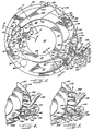
- FIG. 1 is a perspective view of an exemplary embodiment of the invention with portions broken away to reveal the internal structure, and with the associated electrical control system illustrated in the form of a block diagram;
- FIG. 2 is an enlarged, exploded perspective view of the rotatable disc and the stationary sorting head or guide plate in the machine of FIG. 1, with the configuration of the underside of the guide plate superimposed on the top surface of the rotatable disc;
- FIG. 3 is a further enlarged plan view of the sorting head or guide plate in the machine of FIG. 1;
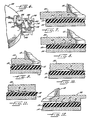
- FIG. 4 is an enlarged perspective view of the right-hand portion of the sorting head as viewed in FIG. 3, illustrating the effect of the mechanism on coins of a first denomination having a relatively small diameter;
- FIG. 5 is a perspective view of the same mechanism illustrated in FIG. 4, but showing the effect of the mechanism on coins of a second denomination having a relatively large diameter;
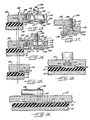
- FIG. 6 is a perspective view of the top of the same portion of the sorting head shown in FIGS. 4 and 5;
- FIG. 7 is a section taken generally along line 7-7 in FIG 3;
- FIG. 8 is a section taken generally along line 8-8 in FIG. 3;
- FIG. 9 is a section taken generally along line 9-9 in FIG. 3;
- FIG. 10 is an enlarged section taken generally along line 10-10 in FIG. 3;
- FIG. 11 is an enlarged section taken generally along line 11-11 in FIG. 3;
- FIG. 12 is an enlarged section taken generally along line 12-12 in FIG. 3;
- FIG. 13 is an enlarged section taken generally along line 13-13 in FIG. 3;
- FIG. 14 is an enlarged section taken generally along line 14-14 in FIG. 3;
- FIG. 15 is an enlarged section taken generally along line 15-15 in FIG. 3;
- FIG. 16 is an enlarged section taken generally along line 16-16 in FIG. 3;
- FIG. 17 is an enlarged section taken generally along line 17-17 in FIG. 3; and
- FIG. 18 is an enlarged section taken generally along line 18-18 in FIG. 3.
- While the invention is susceptible to various modifications and alternative forms, specific embodiments thereof have been shown by way of example in the drawings and will be described in detail herein. It should be understood, however, that it is not intended to limit the invention to the particular forms disclosed, but, on the contrary, the intention is to cover all modifications, equivalents, and alternatives falling with the scope of the invention as defined by the appended claims.
- Referring initially to FIG. 1, there is shown a
coin sorter 10 having a resilient disc in the form ofpad 12 of an elastomer construction rotated on and by aturntable 14 driven by amotor 16via belt 17. A hopper 18 (partially broken away) is positioned about acentral opening 20 in astationary guide plate 22, and coins to be sorted are inserted through this hopper. Theguide plate 22 is supported, by means not shown, at a selected spacing with respect to thepad 12, typically 0.005 to 0.010 inch. A centrally positioned hub 24 extends upwardly through an opening (not shown) in thepad 12 and is conventionally secured as by a threaded connection to theturntable 14. The hub 24 has a tapered surface which functions to direct coins in an off-center direction so that there will always be some centrifugal force tending to cause coins to move outwardly toward the inner periphery of theguide plate 22. - Referring now additionally to FIGS. 2-18, the underside of the
guide plate 22 in configured to guide coins rotated by the pad 12 (in the direction of the arrows in FIG. 2) in a circular and then spiral path within aninner recess 34 which overall is oval in configuration and forms a guide edge 30. The coins are moved, as illustrated by coins 26 in FIG. 2, outwardly by centrifugal force in a path governed by the tapered inner facing edge 30 of therecess 34. Thisrecess 34 generally has a depth on the order of 0.005 to 0.010 inch deeper than the thickness coin to be sorted. Thus, the coins are free to move radially beneath the top surface of therecess 34. The first part of the coins' travel is generally circular from point 38 to point 40 (FIG. 3) and within that region most of the coins are formed in a single file. - At approximately point 42 (FIG. 3), the edge 30 of the central portion 35 of the
recess 34 transitions, in a recess portion 44 (FIG. 3), from being circular to a spiral, and thereafter coins are moved outwardly, along edge 43, by the combination of circular movement of thepad 12 and centrifugal force. The recess region 44 may be of the same depth or slightly shallower than other portions of therecess 34, the latter being the case where the thickness of the thickest coin to be sorted is greater than the thickness of two of the thinnest coins to be sorted. In all cases, the depth is preferably less than the thickness of the two thinnest coins to be sorted, typically 0.010 to 0.020 inch less in depth. Where it is necessary to provide reduced depth, there is preferably a gradual transition or slight ramp downwardly between central portion 35 of therecess 34 and the recess region 44 and downwardly between the recess region 44 and a region 67. This dimension in the recess portion 44 is required in order to separate two thin coins, such as illustrated by coins 50 and 52 in FIG. 2) when they have assumed a position where one coin is on top of the other, as shown. - Separation is effected by a guide 54 (FIGS. 2 and 3) as follows. With the depth of recess region 44 less than the thickness of the two piggyback coins 50 and 52, the bottom coin 52 is frictionally engaged by the pad 12 (FIG. 1) and moved beneath the guide 54 in a generally circular path as depicted by the dashed line positions of this coin in FIG. 2. Thereafter, the coin moves back into the
recess 34. Finally, the coin is free of compression inrecess 34, enabling it to be simply recirculated around on thepad 12. Meanwhile, the upper coin 50 is restrained by an upper flat portion 63 (FIG. 8) of the leading edge 58 of the guide 54, and this coin passes outboard of the guide 54. The guide 54 fully tapers at thepoint 40 from the recess region 44 to the lowermost surface of the guide 54 so that a coin striking this point simply rides over the guide 54 and is recirculated. - The recess region 44 also forms a restricted passageway for a single file of small coins, for example, pennies and dimes of U.S. coinage. This passageway is formed between an outward projection 62 of the guide 54 and the outer edge 64 of the recess region 44. The edge 30 and its extension 64 are both tapered as shown in FIG. 8, this taper effecting a wedging action of coins to prevent bounce.
- Larger coins (e.g., a nickel, quarter, Susan B. Anthony dollar, or half dollar of U.S. coinage), such as illustrated by the
coin 66 in FIGS. 2 and 3, actually cartwheel outwardly into a recessed area 68 and thereby move around the projection 62 until they are moved circularly beyond the recess region ofrecess 34 where they are free to move outwardly by centrifugal force. The recessed area 68 is of less depth than the recess region 44. As a result, the larger coins are actually captured by thepad 12 and rotated by it. Theouter edge region 69 of the guide 54 lies generally in a fixed radial configuration in order to enable a sufficiently large area of the recess region 44 to accommodate free movement of coins by centrifugal force. As a result, the larger coins, and, of course, the smaller ones also, move along the spiraling edge 42 to a generallycircular edge 72, as illustrated by the coin 71. - In the event that a coin is, for some reason, on top of another coin within the area 67 of the
recess 34, an edge 78 of the guide 54, having an upper straight edge region 73 and a lower tapered edge 77 (FIG. 10), will effect a separation of the coins, causing the lower of the coins to be moved over the guide 54 as described for the separation and movement of coins 50 and 52. The edge 78 thus breaks up any jams that may form between coins, as by doubling, and captures any coins moved against edge 78 and causes them to be recirculated back into therecess 34 for reforming in a single file. - Freely moving coins finally form in a single file and are rotated by
pad 12 to a position where they engage a downwardly extendingramp 76, as illustrated by the coin 71 in FIGS. 3 and 11. Theramp 76 effects a depression of the coins into thepad 12, so that the coins are captured at their then radial position. The dashed line 80 in FIG. 3 indicates a maximum diameter circular path along which the captured coins may progress, as shown by coin 82. This path may be inward somewhat depending on where the coins are captured byramp 76. - Coins are next rotated into a
tapered recess 90, the contour of which is illustrated in FIG. 12. Most significantly, therecess 90 is tapered upwardly and inwardly includes an outwardly curving coin positioning edge 92. A coin 94 is shown in FIG. 3 as being within therecess 90 along the circular path of the dashed line 80 until this coin is rotated to a position where its inner edge engages the edge 92 of therecess 90. When this occurs, the coin is urged outwardly along the edge 92 to apoint 101 where the edge 92 merges into ramp 103, as illustrated by coin 100 in FIG. 3. The ramp 103 is configured like theramp 76 shown in FIG. 11 and functions to urge a coin downwardly, as would be the case for acoin 104. Thereafter, coins are rotated with their inner edges radially referenced to this point. The dashedline 106 in FIG. 3 illustrates this path of rotation, andcoin 104 illustrates a con following it. Significantly, this means that the outer edges of the coins traverse circular paths which are uniquely determined by their diameters. It follows that a circular path of the outer edge of a half dollar is at a larger radius of rotation than smaller diameter coins. - While operation of the illustrative device has generally been described above, it will be reviewed. First, coins of different diameters to be sorted are placed in the
hopper 18, and thus deposited on thepad 12. When themotor 16 is started, thepad 12 rotates in the direction of the arrows in FIG. 2, and the coins are moved by centrifugal force outwardly and into therecess 34 where they form in a single file against the guide edge 30. They are then moved outwardly where any doubled small coins, e.g., dimes, are separated by capturing the lower one and moving it under the guide 54. Smaller denomination coins, such as dimes and pennies, pass outwardly of the guide 54 within recess region 44 between the guide 54 and the guide edge 64. Larger coins are enabled to pass by a reduced depth recessed area 68 within which the larger coins (e.g., coin 66) effectively cartwheel outwardly and are then rotated back into the full depth recess 67. Coins in the recess 67 freely move outwardly by centrifugal force as in the case of coin 71. In case there exist in this recess doubled coins, one coin on top of the other, the coins are separated by the edge 78, enabling the lower of the coins to pass under the edge 78. - A coin normally passing outwardly within the recess 67 is stopped by the
edge 72 and rotated under theramp 76 which effects a capturing of the coin, as in the case of coins 71 and 82. Coins so captured are rotated under a recessedarea 90. Thisarea 90 is of less depth than the recessedarea 34, and thus coins continue to be captured but are readily susceptible to radial movement when engaged by the inner edge 92 of therecess 90. The edge 92 moves the coins outwardly until the inner edges of the coins reach the reference radius designated by the dashedline 106. At this point, the coins are depressed further downward by the ramp 103 and fully captured by the lower surface of theguide plate 22, as in the case ofcoin 104. - As the coins are rotated along the ramp 103, they approach a
coin selector assembly 107 which includes a radially adjustable, generallyrectangular ramp member 108 and a rigidly mountedbase 110. Thebase 110 is fastened to theguide plate 22 by screws 112 and has two opposed and elongatedkey slots 114 and 116;slot 114 is formed in the upper surface 118 of thebase 110, and slot 116 is formed in the lower surface 120 of thebase 110. An elongated opening 122 is centrally positioned and extends lengthwise in theslots 114 and 116. - The top of the
ramp member 108 forms a key 126 which is dimensioned to slidably engage the bottom slot 116 in thebase 110. Centrally located and extending perpendicular to the surface 128 of the key 126 is a threadedshaft 130 which extends through the opening 122 in thebase 110. A referencing key 132 having anopening 134 and a referencingedge 136 is dimensioned to slidably engage theupper slot 114 in thebase 110 and is mounted in theslot 114 with the threadedshaft 130 extending through theopening 134 in the key 132. A clamping handle 138 having a threadedopening 140 is threaded onto theshaft 130 so that thekeys 126 and 136 may be tightly clamped within theslots 114 and 116, thus clamping theramp member 108 in a selected position. Rigidly mounted on thetop surface 144 of theguide plate 22 is an L-shaped referencingmember 142 which, in conjunction with theindexing edge 136 of the key 132, allows for the precise positioning of theramp 108 to selectively separate a single denomination of coin from a mix of coins, as will be described in more detail below. - As can be seen in FIGS. 3-5, the inboard edge of the
ramp member 108 forms two indexingsurfaces indexing surfaces coin sorter probe 150 which is electrically insulated from theramp 108 and thus theguide plate 22 by an insulatingsleeve 152. Theprobe 150 is clamped into aslot 154 in theramp member 108 by aclamp block 156 and screw 158 (FIG. 17). The inner end 148 of the probe 150 (FIGS. 3 and 14) is connected to a coin detecting and counting circuit, which will be further described below. As can be seen FIGS. 4 and 5, aportion 160 of the lower surface of theramp member 108 is inclined while another portion 162 is relatively flat. - In the area adjacent the
ramp member 108, theguide plate 22 is contoured (see FIG. 16) to work in conjunction with theramp member 108 to effect the separation of a chosen donomination of coins. More specifically, the downwardly extending ramp 103 terminates in acapture area 164 which has a radially inwardly extendinginner edge 166 including anoverride notch 168 within theedge 166. Thecapture area 164 leads to an upwardly extending ramp 170 which leads to anexit recess 172 forming an inboard guide wall 174. The guide wall 174 extends outwardly to theedge 176 of theguide plate 22 and functions to guide coins of undesired denominations out from under theguide plate 22 to a chute 177 (FIG. 1) leading to a bag or other coin receptacle. Conversely, theoverride notch 168 allows coins of the desired denomination to override theedge 166, become captured by thepad 12, and be rotated at a fixed radial position against the lowermost surface 178 of theguide plate 22 toward asecond exit recess 180. Theexit recess 180 has an inlet ramp 182 and aninboard guide wall 184 which extends outwardly to theouter periphery 176 of theguide plate 22 and functions to guide coins out from under theplate 22 to achute 183. To stop the flow of coins along theexit recess 180, as when a predetermined number of coins have been discharged, an opening 186 (FIG. 18) is provided inrecess 180 and contains a solenoid-operation stop shoe 188. Theshoe 188 is normally retracted, as shown in FIG. 18, allowing coins to traverse theguide edge 184. - The
coin selector assembly 107 is set to sort a particular denomination of coin, as shown in FIGS. 6, 13 and 14, by placing acoin 190 of the desired denomination between the referencingmember 142 and the referencingedge 136 of the key 132. Theramp member 108 is then pushed to the left (as viewed in FIG. 6) so that thecoin 190 is firmly clamped between themember 142 and the referencingedge 136 of the key 132, and thehandle 138 is rotated to clamp theramp member 108 in that position. This causes the probe end 148 and theindexing edge 146 of theramp 108 to be positioned at a distance opposite thenotch 168 which is slightly less than the diameter of the referenced coin. Consequently, coins of the selected diameter (denomination) strike the probe end 248 and are moved inwardly into thenotch 168, thereby causing those coins to be captured by pressing their inboard edges into thepad 12, inboard of the guide edge 174 of thefirst exit recess 172. Thus, coins of the selected denomination are reindexed along their outboard edges by the probe tip 148 and theedge 146 of theramp 108. Coins of other denominations do not touch the probe end 148 oredge 146, as will be explained below. - Referring now to FIG. 1, a control circuit is shown which allows a selected number of coins of a selected denomination to be ejected from the
sorter 10 and guided by thechute 183 into an appropriate receptacle. This is accomplished by a motor control 194 and a delayed stop solenoid 196 for thestop shoe 188, both of which are activated by a signal from a coin detector andcounter 198. A display 200 provides a visual readout from thecounter 198. During operation, coins of the selected denomination are detected and counted as they strike the probe 148 until a prescribed count is reached, whereupon an activating signal is sent to the motor control 194 and atime delay circuit 202. The motor control 194 in turn applies a braking current tomotor 16, rapidly braking themotor 16 and thus theturntable 14 and thepad 12 to a stop. Asmotor 16 cannot be stopped instantaneously, atime delay circuit 202 provides a delay of 0.1 to 0.2 seconds before energizing anelectronic switch 204 and the relay 196. This delay allows the last counted coin to clear thesorter 10 before the solenoid 196 is energized to advance thestop shoe 188 and thereby recycle coins. - FIG. 4 shows the sequential positions of a
coin 206 which is smaller than the selected coin engaged by the probe tip 148. As stated earlier, all coins are initially captured by thepad 12 and held with their inboard edges at the radius of point 100. Then, as thecoin 206 rides under the ramp 102, it is pressed further into thepad 12 and captured even more firmly as it rides under thecapture area 164 between theramp member 108 and thenotch 168. Without interacting with either thenotch 168 or theramp member 108, thecoin 206 continues under the ramp 170 and into theexit recess 172 where the pressure on thecoin 206 is partially released so that the coin may be more easily moved radially outwardly and ejected by the guide edge 174. - FIG. 5 shows the sequential positions of a
coin 208 which is larger than the selected coin size. As thecoin 208 rides under ramp 102, it is fully captured bypad 12, but because its diameter is larger than the selected coin size, the outboard portion of thecoin 208 rides under theinclined portion 160 of theramp member 108. This tips thecoin 208 upward along its inboard edge into thegroove 166. The coin is still captured by thepad 12, which rotates the coin in a radially fixed position toward theexit recess 172. Thegroove 166 accommodates the inboard edge of thecoin 208 as it is tipped and helps guide the coin into theexit recess 172. As in the case of thesmaller coins 206, thecoin 208 rides under the releasing ramp 170 and into theexit recess 172 where the coin is moved outwardly and ejected by the guide edge. - Referring now to FIG. 3, a
coin 104 having the same diameter as thereference coin 190 is shown in sequential positions. As described above, thecoin 104 is rotated under the ramp 102 and fully captured under thecapture area 164 where the outboard edge of thecoin 104 strikes and is reindexed by the probe tip 148. This moves thecoin 104 slightly inboard so that the inboard edge of thecoin 104 is urged into thenotch 168, which in turn allows thepad 12 to capture thecoin 104. Thecoin 104 is then rotated by thepad 12 past the ejection guide edge 174 along the lowermost surface of theguide plate 22 and toward thesecond exit recess 180. As long as a full count of coins has not been reached and the stop solenoid 196 is not energized, thecoin 104 travels under the releasing ramp 182 into theexit recess 180 where the coin is moved outwardly and ejected by theguide edge 184. - When a full count of coins is reached, the
stop shoe 188 is lowered to the position shown in phantom in FIG. 18, so that thecoin 104′ is not allowed to enter theexit recess 180. Instead, thecoin 104′ is rotated over thestop shoe 188, theguide edge 184, and toward arecycling recess 210. Abeveled guide edge 212 in therecycling recess 210 guides coins inwardly toward the single file of coins forming against the edge 30 where they are merged to form a single file of coins moving toward theramp 76. Astrike plate 214 is mounted as shown to assist larger coins in their inward movement to prevent any stray coins from being inadvertently ejected from under theguide plate 22.
Claims (16)
a rotatable disc (12) having a resilient surface (12) for receiving said mixed denomination coins and imparting rotational movement to said mixed denomination coins,
means (14, 16, 17) for rotating said disc (12),
a stationary guide plate (22) having a contoured surface spaced slightly away from and generally parallel to said resilient surface (12) of said rotatable disc, coins on said disc into a single file of coins and a guiding edge (30) which engages the inner edges of the coins in said single file and guides said coins along a first prescribed path where the positions of the outer edges of the coins are determined by the diameters of the respective coins,
means for engaging (54, 64) said the outer edges of a selected denomination to displace the engaged coins from said first prescribed path to a second prescribed path where the inner edges of the coins of said selected denomination are radially offset from the inner edges of coins of other denominations, and
means (182, 184) for discharging coins of said selected denomination at a predetermined exit location (186) on said second prescribed path.
discharge means (172, 174) aligned with said first prescribed path for removing the bypassing coins from between said rotatable (12) and stationary (22) discs.
Applications Claiming Priority (2)
| Application Number | Priority Date | Filing Date | Title |
|---|---|---|---|
| US07/079,683 US4966570A (en) | 1987-07-30 | 1987-07-30 | Coin sorting apparatus for sorting coins of selected denominations |
| US79683 | 1987-07-30 |
Publications (2)
| Publication Number | Publication Date |
|---|---|
| EP0301683A2 true EP0301683A2 (en) | 1989-02-01 |
| EP0301683A3 EP0301683A3 (en) | 1990-03-14 |
Family
ID=22152135
Family Applications (1)
| Application Number | Title | Priority Date | Filing Date |
|---|---|---|---|
| EP88304119A Withdrawn EP0301683A3 (en) | 1987-07-30 | 1988-05-06 | Coin sorting apparatus and rotating disc |
Country Status (6)
| Country | Link |
|---|---|
| US (3) | US4966570A (en) |
| EP (1) | EP0301683A3 (en) |
| JP (1) | JP2731536B2 (en) |
| BR (1) | BR8803238A (en) |
| CA (1) | CA1321368C (en) |
| MX (1) | MX164963B (en) |
Cited By (7)
| Publication number | Priority date | Publication date | Assignee | Title |
|---|---|---|---|---|
| WO1992008212A1 (en) * | 1990-10-30 | 1992-05-14 | Cummins-Allison Corp. | Disc-type coin sorter with adjustable gaging device |
| EP0528807A1 (en) * | 1990-05-14 | 1993-03-03 | Cummins Allison Corp | Coin sorter with automatic bag-switching or stopping. |
| EP0685095A4 (en) * | 1992-09-25 | 1995-09-29 | Cummins Allison Corp | Coin handling system. |
| EP0784298A1 (en) * | 1996-01-11 | 1997-07-16 | Cummins-Allison Corporation | Improved coin sorter |
| US5997395A (en) * | 1998-03-17 | 1999-12-07 | Cummins-Allison Corp. | High speed coin sorter having a reduced size |
| US6171182B1 (en) | 1992-09-25 | 2001-01-09 | Cummins-Allison Corp. | Coin handling system with shunting mechanism |
| EP2905755A1 (en) * | 2014-02-10 | 2015-08-12 | Outerwall Inc. | Coin input apparatuses and associated methods and systems |
Families Citing this family (60)
| Publication number | Priority date | Publication date | Assignee | Title |
|---|---|---|---|---|
| US4966570A (en) * | 1987-07-30 | 1990-10-30 | Ristvedt Victor G | Coin sorting apparatus for sorting coins of selected denominations |
| US5106338A (en) * | 1989-03-14 | 1992-04-21 | Cummins-Allison Corp. | Coin sorting mechanism |
| US5542880A (en) * | 1990-05-14 | 1996-08-06 | Cummins-Allison Corp. | Coin handling system with shunting mechanism |
| US5507379A (en) * | 1990-05-14 | 1996-04-16 | Cummins-Allison Corp. | Coin handling system with coin sensor discriminator |
| US5429550A (en) * | 1990-05-14 | 1995-07-04 | Cummins-Allison Corp. | Coin handling system with controlled coin discharge |
| US5205780A (en) * | 1991-04-29 | 1993-04-27 | Cummins-Allison Corporation | Disc-type coin sorter with eccentric feed |
| US5163866A (en) * | 1991-04-29 | 1992-11-17 | Cummins-Allison Corp. | Disc-type coin sorter with multiple-path queuing |
| US5163867A (en) * | 1991-05-15 | 1992-11-17 | Cummins-Allison Corp. | Disc-type coin sorter with multiple-path queuing |
| US5145455A (en) * | 1991-05-15 | 1992-09-08 | Cummins-Allison Corp. | Wave-type coin sorter |
| AU651220B2 (en) * | 1991-06-03 | 1994-07-14 | Cummins-Allison Corp. | Disc-type coin sorter |
| US5372542A (en) * | 1993-07-09 | 1994-12-13 | Cummins-Allison Corp. | Disc coin sorter with improved exit channel |
| US5468182A (en) * | 1993-08-05 | 1995-11-21 | Cummins-Allison Corp. | Disc-type coin sorter with adjustable targeting inserts |
| US5401211A (en) * | 1993-08-05 | 1995-03-28 | Cummins-Allison Corp. | Disc coin sorter with positive guide wall between exit channels |
| US5514034A (en) * | 1993-09-28 | 1996-05-07 | Cummins-Allison Corp. | Apparatus and method for terminating coin sorting using pressureless exit channels and immediate stopping |
| US5370575A (en) * | 1994-01-06 | 1994-12-06 | Cummins-Allison Corp. | Coin sorting mechanism |
| US5501631A (en) * | 1994-01-06 | 1996-03-26 | Cummins-Allison Corp. | Coin handling device with an improved lubrication system |
| US5425669A (en) * | 1994-01-07 | 1995-06-20 | Cummins-Allison Corp. | Coin queuing and sorting arrangement |
| US5607351A (en) * | 1994-11-10 | 1997-03-04 | Automated Currency Instruments, Inc. | Coin counting machine |
| US6748101B1 (en) | 1995-05-02 | 2004-06-08 | Cummins-Allison Corp. | Automatic currency processing system |
| US6363164B1 (en) | 1996-05-13 | 2002-03-26 | Cummins-Allison Corp. | Automated document processing system using full image scanning |
| US5782686A (en) * | 1995-12-04 | 1998-07-21 | Cummins-Allison Corp. | Disc coin sorter with slotted exit channels |
| US8950566B2 (en) | 1996-05-13 | 2015-02-10 | Cummins Allison Corp. | Apparatus, system and method for coin exchange |
| TW374892B (en) * | 1998-03-02 | 1999-11-21 | Asahi Seiko Co Ltd | Sporting and sieving device for coins |
| JP2926047B1 (en) * | 1998-06-15 | 1999-07-28 | 有限会社スガイ総業 | Coin counting device |
| US6431342B1 (en) | 1999-09-13 | 2002-08-13 | Andrew Schwartz | Object routing system |
| US8701857B2 (en) | 2000-02-11 | 2014-04-22 | Cummins-Allison Corp. | System and method for processing currency bills and tickets |
| US6896118B2 (en) | 2002-01-10 | 2005-05-24 | Cummins-Allison Corp. | Coin redemption system |
| US7743902B2 (en) | 2002-03-11 | 2010-06-29 | Cummins-Allison Corp. | Optical coin discrimination sensor and coin processing system using the same |
| AT6405U1 (en) | 2002-06-05 | 2003-10-27 | Card Casinos Austria Res & Dev | CHIP SORTING DEVICE |
| US7934980B2 (en) * | 2002-06-05 | 2011-05-03 | Shuffle Master Gmbh & Co Kg | Chip stack cutter devices for displacing chips in a chip stack and chip-stacking apparatuses including such cutter devices |
| WO2003107280A2 (en) | 2002-06-14 | 2003-12-24 | Cummins-Allison Corp. | Coin redemption machine having gravity feed coin input tray and foreign object detection system |
| US8171567B1 (en) | 2002-09-04 | 2012-05-01 | Tracer Detection Technology Corp. | Authentication method and system |
| US20040092222A1 (en) * | 2002-11-07 | 2004-05-13 | Bogdan Kowalczyk | Stationary head for a disc-type coin processing device having a solid lubricant disposed thereon |
| US6976589B2 (en) * | 2003-02-03 | 2005-12-20 | Streamline Innovations Gmbh | Apparatus for sorting articles |
| US6966417B2 (en) * | 2003-02-10 | 2005-11-22 | Cummins-Allison Corp. | Coin chute |
| US8393455B2 (en) | 2003-03-12 | 2013-03-12 | Cummins-Allison Corp. | Coin processing device having a moveable coin receptacle station |
| US9934640B2 (en) | 2004-09-15 | 2018-04-03 | Cummins-Allison Corp. | System, method and apparatus for repurposing currency |
| US8523641B2 (en) | 2004-09-15 | 2013-09-03 | Cummins-Allison Corp. | System, method and apparatus for automatically filling a coin cassette |
| US7427230B2 (en) * | 2004-12-10 | 2008-09-23 | Cummins-Allison Corp. | Resilient pad for disc-type coin processing device |
| US8602200B2 (en) | 2005-02-10 | 2013-12-10 | Cummins-Allison Corp. | Method and apparatus for varying coin-processing machine receptacle limits |
| WO2007044570A2 (en) | 2005-10-05 | 2007-04-19 | Cummins-Allison Corp. | Currency processing system with fitness detection |
| US7980378B2 (en) | 2006-03-23 | 2011-07-19 | Cummins-Allison Corporation | Systems, apparatus, and methods for currency processing control and redemption |
| US8042732B2 (en) | 2008-03-25 | 2011-10-25 | Cummins-Allison Corp. | Self service coin redemption card printer-dispenser |
| US8336699B2 (en) | 2009-11-02 | 2012-12-25 | Shuffle Master Gmbh & Co Kg | Chip sorting devices, components therefor and methods of ejecting chips |
| US8545295B2 (en) | 2010-12-17 | 2013-10-01 | Cummins-Allison Corp. | Coin processing systems, methods and devices |
| US9092924B1 (en) | 2012-08-31 | 2015-07-28 | Cummins-Allison Corp. | Disk-type coin processing unit with angled sorting head |
| US10685523B1 (en) | 2014-07-09 | 2020-06-16 | Cummins-Allison Corp. | Systems, methods and devices for processing batches of coins utilizing coin imaging sensor assemblies |
| US9916713B1 (en) | 2014-07-09 | 2018-03-13 | Cummins-Allison Corp. | Systems, methods and devices for processing coins utilizing normal or near-normal and/or high-angle of incidence lighting |
| US11410481B2 (en) | 2014-07-09 | 2022-08-09 | Cummins-Allison Corp. | Systems, methods and devices for processing batches of coins utilizing coin imaging sensor assemblies |
| US9501885B1 (en) | 2014-07-09 | 2016-11-22 | Cummins-Allison Corp. | Systems, methods and devices for processing coins utilizing near-normal and high-angle of incidence lighting |
| US9508208B1 (en) | 2014-07-25 | 2016-11-29 | Cummins Allison Corp. | Systems, methods and devices for processing coins with linear array of coin imaging sensors |
| US9430893B1 (en) | 2014-08-06 | 2016-08-30 | Cummins-Allison Corp. | Systems, methods and devices for managing rejected coins during coin processing |
| US10089812B1 (en) | 2014-11-11 | 2018-10-02 | Cummins-Allison Corp. | Systems, methods and devices for processing coins utilizing a multi-material coin sorting disk |
| US9875593B1 (en) | 2015-08-07 | 2018-01-23 | Cummins-Allison Corp. | Systems, methods and devices for coin processing and coin recycling |
| US9836909B2 (en) | 2016-04-06 | 2017-12-05 | Shuffle Master Gmbh & Co Kg | Chip sorting devices and related assemblies, components and methods |
| US10679449B2 (en) | 2016-10-18 | 2020-06-09 | Cummins-Allison Corp. | Coin sorting head and coin processing system using the same |
| US10181234B2 (en) | 2016-10-18 | 2019-01-15 | Cummins-Allison Corp. | Coin sorting head and coin processing system using the same |
| US10096192B1 (en) | 2017-08-30 | 2018-10-09 | Shuffle Master Gmbh & Co Kg | Chip sorting devices and related assemblies and methods |
| GB2616984B (en) | 2019-01-04 | 2024-02-21 | Cummins Allison Corp | Coin pad for coin processing system |
| EP3770084B1 (en) * | 2019-07-26 | 2023-05-24 | Albert Handtmann Maschinenfabrik GmbH & Co. KG | Sausage casing storage with level monitoring |
Citations (2)
| Publication number | Priority date | Publication date | Assignee | Title |
|---|---|---|---|---|
| CH650871A5 (en) * | 1982-12-16 | 1985-08-15 | Marcel Brisebarre C O Epitaux | Machine for automatically sorting coins |
| EP0151776A2 (en) * | 1983-12-21 | 1985-08-21 | Brandt, Inc. | Coin sorter |
Family Cites Families (51)
| Publication number | Priority date | Publication date | Assignee | Title |
|---|---|---|---|---|
| US574528A (en) * | 1897-01-05 | Coin separator and distributer | ||
| US1979659A (en) * | 1928-01-30 | 1934-11-06 | Ambrose E Zierick | Coin sorting machine |
| US1894190A (en) * | 1930-12-05 | 1933-01-10 | Herbert B Myers | Coin assorting and counting machine |
| US2231642A (en) * | 1934-07-02 | 1941-02-11 | Automatic Coinwrapping Machine | Coin machinery |
| US2348936A (en) * | 1940-10-11 | 1944-05-16 | Brandt Automatic Cashier Co | Coin sorting and counting machine |
| US2351197A (en) * | 1941-02-15 | 1944-06-13 | Sattley Company | Coin sorting machine |
| US2835260A (en) * | 1954-02-11 | 1958-05-20 | Brandt Automatic Cashier Co | Coin sorting and counting machine |
| DE1137884B (en) * | 1955-05-31 | 1962-10-11 | Brandt Automatic Cashier Compa | Coin sorting device |
| US2906276A (en) * | 1956-03-08 | 1959-09-29 | Brandt Automatic Cashier Co | Coin sorter |
| US2977961A (en) * | 1957-12-06 | 1961-04-04 | Brandt Automatic Cashier Co | Coin sorting machine |
| GB908999A (en) * | 1960-08-16 | 1962-10-24 | Internat Coin Counting Machine | Improvements in machines for sorting and counting coins or similar articles |
| US3065841A (en) * | 1961-01-05 | 1962-11-27 | Anchor Hocking Glass Corp | Selector hopper |
| US3246658A (en) * | 1963-10-31 | 1966-04-19 | Brandt Automatic Cashier Co | Coin counter predetermined count control apparatus |
| DE2012863A1 (en) * | 1970-03-18 | 1971-10-07 | Alfred Krauth Apparatebau Kg P | Rotating coin sorting device with vertical axis of rotation |
| DE7012799U (en) * | 1970-04-04 | 1970-12-10 | Neue Geldzaehlmaschinen Fabrik | ADDITIONAL EQUIPMENT FOR A COIN SORTING MACHINE. |
| US3771538A (en) * | 1971-07-26 | 1973-11-13 | K Reis | Coin sorting and counting machines |
| US3795252A (en) * | 1972-11-20 | 1974-03-05 | Westermann W | Centrifugal coin sorter |
| US3837139A (en) * | 1973-07-05 | 1974-09-24 | H Rosenberg | Apparatus for handling and counting pills and the like |
| US3939954A (en) * | 1974-03-18 | 1976-02-24 | Qonaar Corporation | Check receiving and testing apparatus |
| SE7504126L (en) * | 1974-04-12 | 1975-12-12 | Systems & Technic Sa | COIN SORTING AND COUNTING DEVICE. |
| US3998237A (en) * | 1975-04-25 | 1976-12-21 | Brandt, Inc. | Coin sorter |
| FR2316669A1 (en) * | 1975-07-02 | 1977-01-28 | Vandeputte Fils & Cie | MACHINE FOR SORTING AND POSSIBLY COUNTING COINS AND SIMILAR COINS |
| FR2325119A1 (en) * | 1975-09-22 | 1977-04-15 | Vandeputte & Cie | AUTOMATIC SORTER OF COINS AND SIMILAR COINS ACCORDING TO THEIR DIAMETER |
| CH596616A5 (en) * | 1976-04-01 | 1978-03-15 | Systems & Technics Sa | |
| US4086928A (en) * | 1976-08-06 | 1978-05-02 | Ristvedt Victor G | Coin sorting machine |
| US4098280A (en) * | 1976-10-22 | 1978-07-04 | Ristvedt Victor G | Coin handling machine |
| US4444212A (en) * | 1978-06-30 | 1984-04-24 | Ristvedt-Johnson, Inc. | Coin handling machine |
| US4234003A (en) * | 1978-06-30 | 1980-11-18 | Ristvedt Victor G | Coin handling machine |
| US4360034A (en) * | 1980-04-09 | 1982-11-23 | Joseph C. Gianotti, Trustee | Coin sorter-counter |
| US4531531A (en) * | 1980-11-18 | 1985-07-30 | Ristvedt-Johnson, Inc. | Coin handling machine |
| EP0061302A3 (en) * | 1981-03-21 | 1983-04-27 | Icc Machines Limited | Coin discrimination |
| US4506685A (en) * | 1982-04-19 | 1985-03-26 | Childers Roger K | High-speed coin sorting and counting apparatus |
| US4543969A (en) * | 1983-05-06 | 1985-10-01 | Cummins-Allison Corporation | Coin sorter apparatus and method utilizing coin thickness as a discriminating parameter |
| US4549561A (en) * | 1983-06-13 | 1985-10-29 | Ristvedt-Johnson, Inc. | Coin handling machine |
| US4564037A (en) * | 1983-08-25 | 1986-01-14 | Childers Corporation | Coin-queueing head for high-speed coin-sorting and counting apparatus |
| US4557282A (en) * | 1983-08-25 | 1985-12-10 | Childers Corporation | Coin-sorting wheel and counter for high-speed coin-sorting and counting apparatus |
| US4564036A (en) * | 1983-09-15 | 1986-01-14 | Ristvedt-Johnson, Inc. | Coin sorting system with controllable stop |
| US4570655A (en) * | 1983-09-28 | 1986-02-18 | Raterman Donald E | Apparatus and method for terminating coin sorting |
| US4592532A (en) * | 1983-11-14 | 1986-06-03 | Stith Jr M Randall | Expansible support and method of use |
| ZA849710B (en) * | 1983-12-14 | 1985-12-24 | Ristvedt Johnson Inc | Coin sorter |
| US4731043A (en) * | 1983-12-14 | 1988-03-15 | Ristvedt-Johnson, Inc. | Coin sorter |
| US4586522A (en) * | 1984-04-03 | 1986-05-06 | Brandt, Inc. | Coin handling and sorting |
| US4775353A (en) * | 1985-10-17 | 1988-10-04 | Childers Corporation | Spiral coin-queueing head for high-speed coin-sorting and counting apparatus |
| US4681128A (en) * | 1986-06-23 | 1987-07-21 | Ristvedt Victor G | Coin sorter |
| US4863414A (en) * | 1986-06-23 | 1989-09-05 | Ristvedt Victor G | Coin sorter |
| US4775354A (en) * | 1987-06-29 | 1988-10-04 | Cummins-Allison Corp. | Coin sorting apparatus with rotating disc stationary guide plate for sorting coins by their different diameters |
| US4966570A (en) * | 1987-07-30 | 1990-10-30 | Ristvedt Victor G | Coin sorting apparatus for sorting coins of selected denominations |
| US4921463A (en) * | 1987-10-27 | 1990-05-01 | Cummins-Allison Corporation | Coin sorter with counter and brake mechanism |
| US5009627A (en) * | 1989-03-14 | 1991-04-23 | Cummins-Allison Corp. | Coin sorting mechanism |
| US5026320A (en) * | 1989-11-06 | 1991-06-25 | Cummins-Allison Corporation | Disc-type coin sorter with retractable guide surfaces |
| US5011455A (en) * | 1990-02-12 | 1991-04-30 | Cummins-Allison Corporation | Coin sorter with automatic bag-switching |
-
1987
- 1987-07-30 US US07/079,683 patent/US4966570A/en not_active Expired - Lifetime
-
1988
- 1988-02-26 CA CA000559944A patent/CA1321368C/en not_active Expired - Fee Related
- 1988-05-02 MX MX11335A patent/MX164963B/en unknown
- 1988-05-06 EP EP88304119A patent/EP0301683A3/en not_active Withdrawn
- 1988-06-29 JP JP63162388A patent/JP2731536B2/en not_active Expired - Fee Related
- 1988-06-30 BR BR8803238A patent/BR8803238A/en unknown
-
1992
- 1992-11-10 US US07/976,144 patent/US5297986A/en not_active Expired - Lifetime
-
1994
- 1994-02-09 US US08/193,733 patent/US5538468A/en not_active Expired - Lifetime
Patent Citations (2)
| Publication number | Priority date | Publication date | Assignee | Title |
|---|---|---|---|---|
| CH650871A5 (en) * | 1982-12-16 | 1985-08-15 | Marcel Brisebarre C O Epitaux | Machine for automatically sorting coins |
| EP0151776A2 (en) * | 1983-12-21 | 1985-08-21 | Brandt, Inc. | Coin sorter |
Cited By (18)
| Publication number | Priority date | Publication date | Assignee | Title |
|---|---|---|---|---|
| EP0528807A1 (en) * | 1990-05-14 | 1993-03-03 | Cummins Allison Corp | Coin sorter with automatic bag-switching or stopping. |
| EP0528807A4 (en) * | 1990-05-14 | 1993-03-31 | Cummins-Allison Corporation | Coin sorter with automatic bag-switching or stopping |
| WO1992008212A1 (en) * | 1990-10-30 | 1992-05-14 | Cummins-Allison Corp. | Disc-type coin sorter with adjustable gaging device |
| US5141472A (en) * | 1990-10-30 | 1992-08-25 | Cummins-Allison Corp. | Disc-type coin sorter with adjustable gaging device |
| AU648349B2 (en) * | 1990-10-30 | 1994-04-21 | Cummins-Allison Corp. | Disc-type coin sorter with adjustable gaging device |
| EP0840260A2 (en) | 1992-09-25 | 1998-05-06 | Cummins-Allison Corporation | Coin sorter and method of counting and sorting |
| EP0685095A1 (en) * | 1992-09-25 | 1995-12-06 | Cummins-Allison Corporation | Coin handling system |
| EP0685095A4 (en) * | 1992-09-25 | 1995-09-29 | Cummins Allison Corp | Coin handling system. |
| US6171182B1 (en) | 1992-09-25 | 2001-01-09 | Cummins-Allison Corp. | Coin handling system with shunting mechanism |
| EP0840260A3 (en) * | 1992-09-25 | 2004-11-03 | Cummins-Allison Corporation | Coin sorter and method of counting and sorting |
| EP0784298A1 (en) * | 1996-01-11 | 1997-07-16 | Cummins-Allison Corporation | Improved coin sorter |
| US5865673A (en) * | 1996-01-11 | 1999-02-02 | Cummins-Allison Corp. | Coin sorter |
| US6039644A (en) * | 1996-01-11 | 2000-03-21 | Cummins-Allison Corp. | Coin sorter |
| US6042470A (en) * | 1996-01-11 | 2000-03-28 | Cummins-Allison Corp. | Coin sorter |
| US5997395A (en) * | 1998-03-17 | 1999-12-07 | Cummins-Allison Corp. | High speed coin sorter having a reduced size |
| US6139418A (en) * | 1998-03-17 | 2000-10-31 | Cummins-Allison Corp. | High speed coin sorter having a reduced size |
| US6612921B2 (en) | 1998-03-17 | 2003-09-02 | Cummins-Allison Corp. | High speed coin sorter having a reduced size |
| EP2905755A1 (en) * | 2014-02-10 | 2015-08-12 | Outerwall Inc. | Coin input apparatuses and associated methods and systems |
Also Published As
| Publication number | Publication date |
|---|---|
| AU610872B2 (en) | 1991-05-30 |
| BR8803238A (en) | 1989-02-08 |
| US5538468A (en) | 1996-07-23 |
| JP2731536B2 (en) | 1998-03-25 |
| AU1504688A (en) | 1989-02-02 |
| US4966570A (en) | 1990-10-30 |
| JPS6434477A (en) | 1989-02-03 |
| EP0301683A3 (en) | 1990-03-14 |
| CA1321368C (en) | 1993-08-17 |
| MX164963B (en) | 1992-10-09 |
| US5297986A (en) | 1994-03-29 |
Similar Documents
| Publication | Publication Date | Title |
|---|---|---|
| US4966570A (en) | Coin sorting apparatus for sorting coins of selected denominations | |
| US5080633A (en) | Coin sorting apparatus with rotating disc | |
| US5104353A (en) | Coin sorting apparatus with rotating disc | |
| US5176565A (en) | Coin sorting apparatus with rotating disc | |
| AU660244B2 (en) | Coin sorter with automatic bag-switching or stopping | |
| US5123873A (en) | Coin sorter with automatic bag-switching | |
| EP0442441B1 (en) | Coin sorter with automatic bagswitching | |
| US5022889A (en) | Coin sorter | |
| US5564978A (en) | Apparatus and method for terminating coin sorting using pressureless exit channels and immediate stopping | |
| US5865673A (en) | Coin sorter | |
| US7188720B2 (en) | Disc-type coin processing device having improved coin discrimination system | |
| US4863414A (en) | Coin sorter | |
| EP0555240B1 (en) | Disc-type coin sorter with adjustable gaging device | |
| CA1336277C (en) | Coinsorter | |
| CA2329197C (en) | Coin sorter |
Legal Events
| Date | Code | Title | Description |
|---|---|---|---|
| PUAI | Public reference made under article 153(3) epc to a published international application that has entered the european phase |
Free format text: ORIGINAL CODE: 0009012 |
|
| AK | Designated contracting states |
Kind code of ref document: A2 Designated state(s): DE FR GB IT NL |
|
| PUAL | Search report despatched |
Free format text: ORIGINAL CODE: 0009013 |
|
| AK | Designated contracting states |
Kind code of ref document: A3 Designated state(s): DE FR GB IT NL |
|
| 17P | Request for examination filed |
Effective date: 19900612 |
|
| 17Q | First examination report despatched |
Effective date: 19920626 |
|
| STAA | Information on the status of an ep patent application or granted ep patent |
Free format text: STATUS: THE APPLICATION IS DEEMED TO BE WITHDRAWN |
|
| 18D | Application deemed to be withdrawn |
Effective date: 19940318 |