EP0301955A1 - Turbine thrust reverser having a device for re-orientating the gas flow - Google Patents
Turbine thrust reverser having a device for re-orientating the gas flow Download PDFInfo
- Publication number
- EP0301955A1 EP0301955A1 EP88401937A EP88401937A EP0301955A1 EP 0301955 A1 EP0301955 A1 EP 0301955A1 EP 88401937 A EP88401937 A EP 88401937A EP 88401937 A EP88401937 A EP 88401937A EP 0301955 A1 EP0301955 A1 EP 0301955A1
- Authority
- EP
- European Patent Office
- Prior art keywords
- deflector
- flow
- thrust
- door
- thrust reverser
- Prior art date
- Legal status (The legal status is an assumption and is not a legal conclusion. Google has not performed a legal analysis and makes no representation as to the accuracy of the status listed.)
- Granted
Links
Images
Classifications
-
- F—MECHANICAL ENGINEERING; LIGHTING; HEATING; WEAPONS; BLASTING
- F02—COMBUSTION ENGINES; HOT-GAS OR COMBUSTION-PRODUCT ENGINE PLANTS
- F02K—JET-PROPULSION PLANTS
- F02K1/00—Plants characterised by the form or arrangement of the jet pipe or nozzle; Jet pipes or nozzles peculiar thereto
- F02K1/54—Nozzles having means for reversing jet thrust
- F02K1/64—Reversing fan flow
- F02K1/70—Reversing fan flow using thrust reverser flaps or doors mounted on the fan housing
Landscapes
- Engineering & Computer Science (AREA)
- Combustion & Propulsion (AREA)
- Mechanical Engineering (AREA)
- General Engineering & Computer Science (AREA)
- Chemical & Material Sciences (AREA)
- Structures Of Non-Positive Displacement Pumps (AREA)
- Control Of Positive-Displacement Air Blowers (AREA)
- Control Of Ac Motors In General (AREA)
- Rectifiers (AREA)
- Power Conversion In General (AREA)
- Jet Pumps And Other Pumps (AREA)
- Perforating, Stamping-Out Or Severing By Means Other Than Cutting (AREA)
- Turbine Rotor Nozzle Sealing (AREA)
- Control Of Turbines (AREA)
Abstract
Description
La présente invention concerne un inverseur de poussée pour un turboréacteur du type à double flux.The present invention relates to a thrust reverser for a turbofan of the double flow type.
Ce type de turboréacteur comporte, d'une part, une structure centrale de moteur formant un canal primaire de circulation des gaz dits de flux primaire ou flux chaud qui constitue une veine principale d'éjection et, d'autre part, un canal annulaire, coaxial au précédent formant un canal secondaire de gaz dits de flux secondaire ou flux froid généré par exemple, en amont, par une soufflante et qui constitue une veine secondaire d'éjection. Ledit canal de flux secondaire est délimité par une paroi extérieure qui sépare le flux secondaire du flux extérieur au moteur et par une paroi intérieure constituée par l'enveloppe de ladite structure centrale de moteur.This type of turbojet engine comprises, on the one hand, a central engine structure forming a primary channel for the circulation of so-called primary flow or hot flow gases which constitutes a main ejection stream and, on the other hand, an annular channel, coaxial with the previous forming a secondary channel of gas called secondary flow or cold flow generated for example, upstream, by a blower and which constitutes a secondary ejection stream. Said secondary flow channel is delimited by an external wall which separates the secondary flow from the flow external to the motor and by an internal wall constituted by the envelope of said central motor structure.
Dans les applications aéronautiques, notamment civiles, de ce type de moteur pour lesquelles un taux de dilution de flux secondaire élevé est utilisé, l'inversion de poussée est appliquée principalement ou uniquement au flux froid. Dans ce cas, l'inverseur de poussée peut notamment être intégré dans la structure de la paroi extérieure du canal secondaire.In aeronautical, in particular civil, applications of this type of engine for which a high secondary flow dilution rate is used, the thrust reversal is applied mainly or only to the cold flow. In this case, the thrust reverser can in particular be integrated into the structure of the external wall of the secondary channel.
De tels dispositifs connus d'inversion de poussée comportent généralement une série d'éléments déplaçables qui, dans une position de poussée directe, séparent le flux secondaire du flux extérieur au moteur et, dans une position d'inversion de poussée, dévient le flux secondaire à contre-courant du flux extérieur, à travers l'ouverture dégagée dans la paroi extérieure du canal secondaire par leur déplacement, en même temps qu'ils assurent une obturation du canal secondaire.Such known thrust reversal devices generally comprise a series of displaceable elements which, in a direct thrust position, separate the secondary flow from the flow external to the engine and, in a thrust reversal position, divert the secondary flow against the flow of the external flow, through the opening made in the external wall of the secondary channel by their displacement, at the same time as they provide a sealing of the secondary channel.
Des exemples de réalisation de tels inverseurs de poussée sont montrés par FR-A-2 490 731 où des éléments déplaçables sont constitués par deux coquilles mobiles en rotation autour d'un axe. Les éléments déplaçables peuvent également être constitués d'une pluralité de volets déviateurs ou pétales ou encore des portes sont utilisées, comme le montrent FR-A-2 486 153, FR-A-2 506 843 ou FR-A-2 559 838. Dans ce dernier cas d'utilisation de portes, il est habituel d'adjoindre, à l'extrémité amont de porte, un déflecteur destiné à canaliser l'écoulement inversé. La recherche de performances suffisantes en inversion de jet impose une longueur minimale de ce déflecteur par rapport à la paroi interne d'une porte. Il en résulte que par rapport à la ligne théorique qui prolonge la paroi aérodynamique de veine du flux secondaire constituée par la paroi fixe extérieure amont du canal secondaire, une cavité est formée entre la paroi interne de porte et ladite paroi théorique de veine. L'écoulement est par conséquent dirigé dans cette cavité, lorsque la porte se trouve en position fermée, engendrant des pertes aérodynamiques néfastes au rendement du turboréacteur, dans les phases de fonctionnement correspondant à la poussée directe.Examples of embodiment of such thrust reversers are shown by FR-A-2 490 731 where displaceable elements are constituted by two shells movable in rotation about an axis. The movable elements can also consist of a plurality of diverter or petal flaps or doors are used, as shown in FR-A-2 486 153, FR-A-2 506 843 or FR-A-2 559 838. In the latter case of using doors, it is usual to add, at the upstream end of the door, a deflector intended to channel the reverse flow. The search for sufficient performance in jet inversion imposes a minimum length of this deflector relative to the internal wall of a door. It follows that compared to the theoretical line which extends the aerodynamic wall of the stream of the secondary flow formed by the outer fixed wall upstream of the secondary channel, a cavity is formed between the internal door wall and said theoretical wall of the stream. The flow is therefore directed into this cavity, when the door is in the closed position, generating aerodynamic losses harmful to the performance of the turbojet engine, in the operating phases corresponding to direct thrust.
Le but de l'invention est d'apporter une solution à ce problème qui n'en a pas reçu de satisfaisante dans les dispositions ci-dessus.The object of the invention is to provide a solution to this problem which has not received a satisfactory one in the above arrangements.
Ces buts sont atteints par un inverseur de poussée de turboréacteur caractérisé en ce que ledit déflecteur d'un élément déplaçable en position fermée est placé en aval d'un bord de déviation solidaire de la partie amont de l'inverseur et comporte à son extrémité radialement interne une partie profilée orientée en direction aval suivant un profil voisin de la ligne théorique de délimitation aérodynamique de la veine secondaire de circulation des gaz constituant le flux secondaire.These goals are achieved by a turbojet thrust reverser characterized in that said deflector of a member movable in the closed position is placed downstream of a deflection edge integral with the upstream part of the reverser and has at its end radially internal a profiled part oriented downstream according to a profile close to the theoretical line of aerodynamic delimitation of the secondary stream of gas circulation constituting the secondary flow.
Avantageusement, le déflecteur comporte des ouvertures réglant le débit du flux inverse et éventuellement associées à des ouîes d'orientation du flux qui peuvent être ajustables.Advantageously, the deflector has openings regulating the flow rate of the reverse flow and possibly associated with flow orientation openings which can be adjustable.
L'invention permet ainsi d'obtenir un redressement du flux secondaire, en position de poussée directe, en évitant une pénétration du flux dans la cavité formée du côté de la paroi interne de l'élément déplaçable de l'inverseur de poussée, tout en assurant, en position d'inversion de poussée un réglage optimal du débit de flux inversé et son orientation suivant une direction compatible avec les performances d'inversion requises dans l'application considérée.The invention thus makes it possible to obtain a straightening of the secondary flow, in the direct thrust position, by avoiding penetration of the flow into the cavity formed on the side of the internal wall of the movable element of the thrust reverser, while ensuring, in the thrust reversal position, an optimal adjustment of the reverse flow rate and its orientation in a direction compatible with the reversal performance required in the application considered.
D'autres caractéristiques et avantages seront mieux compris à la lecture qui va suivre de la description d'un mode de réalisation de l'invention, en référence aux dessins annexés sur lesquels :
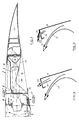
- - la figure 1 représente une demi-vue schématique, en coupe longitudinale par un plan passant par l'axe de rotation d'un turboréacteur, d'une porte d'inverseur de poussée conforme à l'invention, en position fermée et intégré à la paroi externe du canal de flux secondaire ;
- - la figure 2 montre un schéma de porte d'inverseur de poussée conforme à l'invention en position déployée et comportant des ouvertures ;
- - la figure 3 montre un schéma analogue à la figure 2 d'une porte d'inverseur de poussée conforme à l'invention, en position déployée, comportant des ouvertures équipées d'ouîes.
- - Figure 1 shows a schematic half-view, in longitudinal section through a plane passing through the axis of rotation of a turbojet engine, of a thrust reverser door according to the invention, in the closed position and integrated in the outer wall of the secondary flow channel;
- - Figure 2 shows a diagram of the thrust reverser door according to the invention in the deployed position and comprising openings;
- - Figure 3 shows a diagram similar to Figure 2 of a thrust reverser door according to the invention, in the deployed position, having openings equipped with gills.
L'inverseur de poussée de turboréacteur représenté aux figures 1 à 3 est du type à portes constituant les éléments déplaçables de l'inverseur et se compose de trois parties principales, une partie fixe 1 située en amont, dans le prolongement de la paroi interne du canal de flux secondaire ménagé entre ladite paroi et l'enveloppe de structure centrale du turboréacteur, une partie mobile 2 et une virole arrière fixe 3. Ladite partie fixe 1 amont comprend un panneau externe 4 de nacelle, un panneau externe 5 de veine du flux secondaire et un cadre avant 6 qui assure la jonction desdits panneaux 4 et 5. Ledit cadre avant 6 sert également de support au dispositif de commande des déplacements de la partie mobile 2 qui comporte notamment des vérins tels que 7. En aval, amont et aval étant toujours définis par rapport au sens normal de circulation des gaz en poussée directe, la partie fixe 1 se termine par un bord de déviation 8, fixé sous le cadre avant 6 et destiné à assurer une orientation adéquate de l'écoulement, en position d'inversion de poussée. La partie mobile 2 se compose de plusieurs portes 9 déplaçables sous l'action des vérins 7. Chaque porte 9 est composée d'un panneau externe 10, venant se placer en position fermée dans le prolongement du panneau externe 4 de la partie fixe 1 pour constituer la paroi aérodynamique continue limitant le flux extérieur au moteur représenté par la flèche 11, d'un panneau interne 12, d'une structure intérieure 13, assurant la liaison entre lesdits panneaux 10 et 12 et d'un ensemble de déflecteurs destinés à canaliser l'écoulement inversé lorsque l'inverseur se trouve en position d'inversion de poussée et la porte 9 en position ouverte ou déployée. Ladite structure intérieure 13 porte notamment les points de jonction de la tige du vérin 7. L'ensemble des déflecteurs de la porte 9 comporte notamment un déflecteur 14 qui est remarquable selon l'invention. Dans un plan longitudinal par rapport au turboréacteur, comme représenté à la figure 1, le déflecteur 14 de la porte 9 d'inverseur de poussée est situé légèrement décalé vers l'aval par rapport au bord de déviation 8 de la partie fixe amont 1, lorsque la porte 9 se trouve en position fermée correspondant à la position de poussée directe de l'inverseur. Dans cette position, l'extrémité radialement interne du déflecteur 14 se termine par un prolongement 15 présentant une forme profilée qui est orientée en direction aval suivant un profil voisin de la ligne théorique, pour redresser le flux secondaire suivant un profil le plus proche possible de la ligne théorique représentée en 16, correspondant à l'enveloppe de délimitation aérodynamique de la veine du flux secondaire des gaz, représenté par la flèche 17 et qui circule dans le canal secondaire du turboréacteur, par exemple à partir d'une soufflante (non représentée) placée à l'entrée du turboréacteur. Le panneau interne 12 de la porte 9 afin d'assurer en position d'inversion de poussée de ladite porte des performances suffisantes doit s'écarter de la ligne théorique 16, créant ainsi une cavité 18 à l'intérieur de la porte 9 lorsque ladite porte se trouve en position fermée correspondant à la position de poussée directe de l'inverseur, comme elle est représentée à la figure 1.The turbojet thrust reverser shown in FIGS. 1 to 3 is of the door type constituting the displaceable elements of the reverser and consists of three main parts, a fixed part 1 located upstream, in the extension of the internal wall of the secondary flow channel formed between said wall and the casing of the central structure of the turbojet engine, a movable part 2 and a fixed
Dans l'inverseur de poussée conforme à l'invention représenté à la figure 1, les positions relatives du bord de déviation 8 et du déflecteur 14 ainsi que l'adjonction conforme à l'invention d'un prolongement 15 à forme profilée selon la direction choisie à l'extrémité interne du déflecteur 14 permettent d'éviter la distorsion de flux et les perturbations qui proviendraient de l'entrée dans la cavité 18 du flux secondaire 17. Au contraire, par les dispositions de l'invention, ce flux secondaire 17 est astreint à un écoulement limité extérieurement par une enveloppe proche de l'enveloppe aérodynamique théorique de la ligne 16.In the thrust reverser according to the invention represented in FIG. 1, the relative positions of the deflection edge 8 and the
Les dispositions particulières de déflecteur conformes à l'invention qui viennent d'être décrites dans un mode de réalisation d'inverseur de poussée de turboréacteur comportant des portes basculantes sont applicables à tout type d'inverseur comportant des éléments basculants, notamment lorsque ceux-ci sont constitués par des coquilles.The particular deflector arrangements in accordance with the invention which have just been described in an embodiment of a turbojet thrust reverser comprising tilting doors are applicable to any type of reverser comprising tilting elements, in particular when the latter consist of shells.
Il peut résulter, dans certaines applications, des effets combinés de l'allongement du déflecteur et du prolongement profilé de l'extrémité du déflecteur une réduction sensible du débit inversé, en position d'inversion de poussée de l'inverseur. Dans ce cas, comme représenté schématiquement à la figure 2, afin d'obtenir un réglage optimal du débit inversé dont la partie ajustable est représenté par la flèche 19, des ouvertures 20 sont pratiquées dans le déflecteur 14 de la porte 9 d'inverseur. En outre, comme représenté schématiquement à la figure 3, lorsqu'il est avantageux de rechercher une direction optimale compatible avec les performances d'inversion requises dans l'application considérée, les ouvertures 20 sont équipées d'ouîes 21 qui peuvent être fixes ou ajustables en fonction de l'effet recherché.It may result, in certain applications, from the combined effects of the elongation of the deflector and of the profiled extension of the end of the deflector, a significant reduction in the reverse flow rate, in the reverse thrust position of the inverter. In this case, as shown diagrammatically in FIG. 2, in order to obtain an optimal adjustment of the reverse flow, the adjustable part of which is represented by the
Claims (4)
Priority Applications (1)
| Application Number | Priority Date | Filing Date | Title |
|---|---|---|---|
| AT88401937T ATE66521T1 (en) | 1987-07-29 | 1988-07-26 | THRUST REVERSER FOR JET ENGINE WITH ONE FLOW SURFACE. |
Applications Claiming Priority (2)
| Application Number | Priority Date | Filing Date | Title |
|---|---|---|---|
| FR8710730 | 1987-07-29 | ||
| FR8710730A FR2618852B1 (en) | 1987-07-29 | 1987-07-29 | TURBOREACTOR DRIVE INVERTER PROVIDED WITH A FLOW RECTIFIER DEVICE |
Publications (2)
| Publication Number | Publication Date |
|---|---|
| EP0301955A1 true EP0301955A1 (en) | 1989-02-01 |
| EP0301955B1 EP0301955B1 (en) | 1991-08-21 |
Family
ID=9353676
Family Applications (1)
| Application Number | Title | Priority Date | Filing Date |
|---|---|---|---|
| EP88401937A Expired - Lifetime EP0301955B1 (en) | 1987-07-29 | 1988-07-26 | Turbine thrust reverser having a device for re-orientating the gas flow |
Country Status (7)
| Country | Link |
|---|---|
| US (1) | US4858430A (en) |
| EP (1) | EP0301955B1 (en) |
| AT (1) | ATE66521T1 (en) |
| DE (1) | DE3864346D1 (en) |
| ES (1) | ES2025309B3 (en) |
| FR (1) | FR2618852B1 (en) |
| GR (1) | GR3002607T3 (en) |
Cited By (4)
| Publication number | Priority date | Publication date | Assignee | Title |
|---|---|---|---|---|
| EP0368725A1 (en) * | 1988-11-09 | 1990-05-16 | HISPANO-SUIZA Société anonyme dite: | Thrust reverser for a jet-engine provided with deviator flaps with mini-nozzles |
| FR2669079A1 (en) * | 1990-11-14 | 1992-05-15 | Hurel Dubois Avions | Improvement to thrust reversers with doors for a jet aircraft |
| FR2687733A1 (en) * | 1992-02-26 | 1993-08-27 | Hurel Dubois Avions | THRUST INVERTER FOR REACTION ENGINE PROVIDING FLOW GUIDANCE DEVICE. |
| US5396762A (en) * | 1992-12-04 | 1995-03-14 | Societe De Construction Des Avions Hurel-Dubois | Thrust reversal assembly for controlling sidewardly diverted flow |
Families Citing this family (15)
| Publication number | Priority date | Publication date | Assignee | Title |
|---|---|---|---|---|
| US5046307A (en) * | 1988-03-28 | 1991-09-10 | General Electric Company | Thrust reverser for high bypass turbofan engine |
| US5117630A (en) * | 1990-02-12 | 1992-06-02 | Rohr Industries, Inc. | Pivoting door thrust reverser |
| FR2679605A1 (en) * | 1991-07-24 | 1993-01-29 | Snecma | TURBOJET DRIVE INVERTER PROVIDED WITH A SAFETY DEVICE INTEGRATED WITH THE HYDRAULIC CONTROL SYSTEM. |
| FR2683859B1 (en) * | 1991-11-15 | 1994-02-18 | Hispano Suiza | DOUBLE FLOW TURBOREACTOR DRIVE INVERTER. |
| FR2706536B1 (en) * | 1993-06-16 | 1995-07-21 | Snecma | Thrust reverser cylinder comprising an internal locking device and a device for detecting the failure of the internal locking device. |
| FR2712929B1 (en) * | 1993-11-24 | 1995-12-29 | Hispano Suiza Sa | Dual flow turbojet thrust reverser. |
| FR2722534B1 (en) | 1994-07-13 | 1996-08-14 | Hispano Suiza Sa | DOUBLE FLOW TURBOREACTOR DRIVE INVERTER WITH EXTERNAL OBSTACLES |
| EP0763653B1 (en) | 1995-09-13 | 2001-07-18 | SOCIETE DE CONSTRUCTION DES AVIONS HUREL-DUBOIS (société anonyme) | Thrust reverser door with jet deflection cascade |
| FR2740834B1 (en) * | 1995-11-02 | 1997-12-05 | Hispano Suiza Sa | DOUBLE FLOW TURBOREACTOR DRIVE INVERTER WITH SECONDARY DOORS |
| FR2757901B1 (en) * | 1996-12-26 | 1999-01-29 | Hispano Suiza Sa | DOWNSTREAM DOUBLE FLOW TURBOREACTOR DRIVE INVERTER |
| FR2764643B1 (en) * | 1997-06-12 | 1999-07-16 | Hispano Suiza Sa | PUSH INVERTER WITH TURBOREACTOR DOORS WITH VARIABLE EJECTION SECTION |
| DE19749576A1 (en) * | 1997-11-10 | 1999-05-12 | Bmw Rolls Royce Gmbh | Thrust reverser of an aircraft jet engine |
| FR2776023B1 (en) * | 1998-03-12 | 2000-04-07 | Hispano Suiza Sa | TURBOREACTOR DRIVE INVERTER WITH SCOOPING DOORS ASSOCIATED WITH A MOBILE GRID |
| US9038367B2 (en) | 2011-09-16 | 2015-05-26 | United Technologies Corporation | Fan case thrust reverser |
| EP3569853B1 (en) * | 2018-05-15 | 2023-03-01 | Gulfstream Aerospace Corporation | Thrust reverser with continuous curved surface |
Citations (6)
| Publication number | Priority date | Publication date | Assignee | Title |
|---|---|---|---|---|
| US3815357A (en) * | 1971-01-28 | 1974-06-11 | Rohr Industries Inc | Thrust reversing apparatus |
| FR2486153A1 (en) * | 1980-07-04 | 1982-01-08 | Hurel Dubois Avions | THRUST INVERTER FOR A REACTION ENGINE, IN PARTICULAR FOR EQUIPPING AN AIRCRAFT |
| FR2490731A1 (en) * | 1980-09-19 | 1982-03-26 | Snecma | PUSH INVERTER DEVICE FOR MULTIFLUX TURBOREACTOR |
| FR2506843A1 (en) * | 1981-05-29 | 1982-12-03 | Hurel Dubois Avions | PUSH INVERTER DEVICE FOR AIRPLANE TURBOREACTOR |
| FR2559838A1 (en) * | 1984-02-21 | 1985-08-23 | Hurel Dubois Avions | Method and device allowing the control of the reversed jet in jet engines with thrust reverser |
| GB2156004A (en) * | 1984-03-15 | 1985-10-02 | Gen Electric | Thrust modulation device for a gas turbine engine |
Family Cites Families (6)
| Publication number | Priority date | Publication date | Assignee | Title |
|---|---|---|---|---|
| US3280561A (en) * | 1965-06-07 | 1966-10-25 | Gen Electric | Thrust reverser mechanism |
| DE1927280A1 (en) * | 1969-05-29 | 1970-12-03 | Motoren Turbinen Union | Aircraft with one or more turbine jet engines, which are arranged in the fuselage stern or in nacelles and equipped with thrust reversers |
| US3567128A (en) * | 1969-07-02 | 1971-03-02 | Rohr Corp | Thrust reversing apparatus |
| US3570767A (en) * | 1969-10-01 | 1971-03-16 | Rohr Corp | Thrust reversing apparatus |
| US4216923A (en) * | 1977-03-30 | 1980-08-12 | Boeing Commercial Airplane Company | Target type thrust reverser |
| US4340178A (en) * | 1980-05-05 | 1982-07-20 | Rohr Industries, Inc. | Thrust reverser - cascade type |
-
1987
- 1987-07-29 FR FR8710730A patent/FR2618852B1/en not_active Expired
-
1988
- 1988-07-21 US US07/222,555 patent/US4858430A/en not_active Expired - Lifetime
- 1988-07-26 ES ES88401937T patent/ES2025309B3/en not_active Expired - Lifetime
- 1988-07-26 AT AT88401937T patent/ATE66521T1/en not_active IP Right Cessation
- 1988-07-26 DE DE8888401937T patent/DE3864346D1/en not_active Expired - Lifetime
- 1988-07-26 EP EP88401937A patent/EP0301955B1/en not_active Expired - Lifetime
-
1991
- 1991-08-27 GR GR91401235T patent/GR3002607T3/en unknown
Patent Citations (6)
| Publication number | Priority date | Publication date | Assignee | Title |
|---|---|---|---|---|
| US3815357A (en) * | 1971-01-28 | 1974-06-11 | Rohr Industries Inc | Thrust reversing apparatus |
| FR2486153A1 (en) * | 1980-07-04 | 1982-01-08 | Hurel Dubois Avions | THRUST INVERTER FOR A REACTION ENGINE, IN PARTICULAR FOR EQUIPPING AN AIRCRAFT |
| FR2490731A1 (en) * | 1980-09-19 | 1982-03-26 | Snecma | PUSH INVERTER DEVICE FOR MULTIFLUX TURBOREACTOR |
| FR2506843A1 (en) * | 1981-05-29 | 1982-12-03 | Hurel Dubois Avions | PUSH INVERTER DEVICE FOR AIRPLANE TURBOREACTOR |
| FR2559838A1 (en) * | 1984-02-21 | 1985-08-23 | Hurel Dubois Avions | Method and device allowing the control of the reversed jet in jet engines with thrust reverser |
| GB2156004A (en) * | 1984-03-15 | 1985-10-02 | Gen Electric | Thrust modulation device for a gas turbine engine |
Non-Patent Citations (1)
| Title |
|---|
| MACHINE DESIGN, vol. 55, no. 2, janvier 1983, pages 78,79, Cleveland, Ohio, US; G.H. McLAFFERTY: "New thrust control may boost fighter maneuverability" * |
Cited By (5)
| Publication number | Priority date | Publication date | Assignee | Title |
|---|---|---|---|---|
| EP0368725A1 (en) * | 1988-11-09 | 1990-05-16 | HISPANO-SUIZA Société anonyme dite: | Thrust reverser for a jet-engine provided with deviator flaps with mini-nozzles |
| FR2669079A1 (en) * | 1990-11-14 | 1992-05-15 | Hurel Dubois Avions | Improvement to thrust reversers with doors for a jet aircraft |
| FR2687733A1 (en) * | 1992-02-26 | 1993-08-27 | Hurel Dubois Avions | THRUST INVERTER FOR REACTION ENGINE PROVIDING FLOW GUIDANCE DEVICE. |
| EP0558381A1 (en) * | 1992-02-26 | 1993-09-01 | Societe De Construction Des Avions Hurel-Dubois | Thrust reverser for a jet engine ensuring the guidance of the deviated jet |
| US5396762A (en) * | 1992-12-04 | 1995-03-14 | Societe De Construction Des Avions Hurel-Dubois | Thrust reversal assembly for controlling sidewardly diverted flow |
Also Published As
| Publication number | Publication date |
|---|---|
| ATE66521T1 (en) | 1991-09-15 |
| FR2618852A1 (en) | 1989-02-03 |
| GR3002607T3 (en) | 1993-01-25 |
| ES2025309B3 (en) | 1992-03-16 |
| FR2618852B1 (en) | 1989-11-10 |
| US4858430A (en) | 1989-08-22 |
| DE3864346D1 (en) | 1991-09-26 |
| EP0301955B1 (en) | 1991-08-21 |
Similar Documents
| Publication | Publication Date | Title |
|---|---|---|
| EP0301955B1 (en) | Turbine thrust reverser having a device for re-orientating the gas flow | |
| EP0310497B1 (en) | Gas turbine thrust-reversing doors having a flush interior surface | |
| EP0414609B1 (en) | Jet engine cascade thrust reverser without sliding cowling | |
| EP0368725B1 (en) | Thrust reverser for a jet-engine provided with deviator flaps with mini-nozzles | |
| CA2318373C (en) | Thrust reverser with turning vanes capable of being superposed | |
| EP0848153B1 (en) | Thrust reverser for a jet engine with blockdoors and deflector vanes linked to the fixed frame | |
| EP0352171B1 (en) | Thrust reverser for a bypass jet engine with moving deviation flaps | |
| EP0338869B1 (en) | Turbine thrust reverser | |
| EP3415749B1 (en) | Nacelle with thrust reverser system creating limited aerodynamic disturbances | |
| EP0534815B1 (en) | Thrust-reverser with improved guidance of the reversed jets | |
| EP2739841B1 (en) | Reverser having movable cascades, and translatably variable nozzle | |
| WO1999046498A1 (en) | Turbojet thrust reverser with doors forming scoops associated with a mobile grating | |
| FR2978990A1 (en) | PUSH REVERSING DEVICE | |
| WO2010012878A1 (en) | Thrust reverser device | |
| FR2749041A1 (en) | DOUBLE FLOW TURBOREACTOR DRIVE INVERTER WITH PRIMARY HOOD OBSTACLES | |
| EP2635789A2 (en) | Aircraft turbojet engine thrust reverser with a lower number of actuators | |
| FR2764340A1 (en) | DRIVE INVERTER OF TURBOJET WITH DOORS PROVIDED WITH A MOBILE SPOILER WITH OPTIMIZED DRIVE | |
| FR2722534A1 (en) | DOUBLE FLOW TURBOREACTOR DRIVE INVERTER WITH EXTERNAL OBSTACLES | |
| FR2738597A1 (en) | TURBOJET DRIVE INVERTER WITH DOORS ASSOCIATED WITH A PRIMARY PANEL | |
| CA2152883C (en) | Turbofan thrust reverser, with obstructions linked to the primary enclosure |
Legal Events
| Date | Code | Title | Description |
|---|---|---|---|
| PUAI | Public reference made under article 153(3) epc to a published international application that has entered the european phase |
Free format text: ORIGINAL CODE: 0009012 |
|
| 17P | Request for examination filed |
Effective date: 19880812 |
|
| AK | Designated contracting states |
Kind code of ref document: A1 Designated state(s): AT BE CH DE ES FR GB GR IT LI LU NL SE |
|
| 17Q | First examination report despatched |
Effective date: 19900417 |
|
| GRAA | (expected) grant |
Free format text: ORIGINAL CODE: 0009210 |
|
| ITF | It: translation for a ep patent filed |
Owner name: BARZANO' E ZANARDO MILANO S.P.A. |
|
| AK | Designated contracting states |
Kind code of ref document: B1 Designated state(s): AT BE CH DE ES FR GB GR IT LI LU NL SE |
|
| REF | Corresponds to: |
Ref document number: 66521 Country of ref document: AT Date of ref document: 19910915 Kind code of ref document: T |
|
| GBT | Gb: translation of ep patent filed (gb section 77(6)(a)/1977) | ||
| REF | Corresponds to: |
Ref document number: 3864346 Country of ref document: DE Date of ref document: 19910926 |
|
| REG | Reference to a national code |
Ref country code: ES Ref legal event code: FG2A Ref document number: 2025309 Country of ref document: ES Kind code of ref document: B3 |
|
| PLBE | No opposition filed within time limit |
Free format text: ORIGINAL CODE: 0009261 |
|
| STAA | Information on the status of an ep patent application or granted ep patent |
Free format text: STATUS: NO OPPOSITION FILED WITHIN TIME LIMIT |
|
| 26N | No opposition filed | ||
| REG | Reference to a national code |
Ref country code: GR Ref legal event code: FG4A Free format text: 3002607 |
|
| EPTA | Lu: last paid annual fee | ||
| EAL | Se: european patent in force in sweden |
Ref document number: 88401937.3 |
|
| PGFP | Annual fee paid to national office [announced via postgrant information from national office to epo] |
Ref country code: LU Payment date: 19960601 Year of fee payment: 9 |
|
| PGFP | Annual fee paid to national office [announced via postgrant information from national office to epo] |
Ref country code: SE Payment date: 19960613 Year of fee payment: 9 |
|
| PGFP | Annual fee paid to national office [announced via postgrant information from national office to epo] |
Ref country code: GR Payment date: 19960617 Year of fee payment: 9 |
|
| PGFP | Annual fee paid to national office [announced via postgrant information from national office to epo] |
Ref country code: BE Payment date: 19960625 Year of fee payment: 9 |
|
| PGFP | Annual fee paid to national office [announced via postgrant information from national office to epo] |
Ref country code: CH Payment date: 19960711 Year of fee payment: 9 |
|
| PGFP | Annual fee paid to national office [announced via postgrant information from national office to epo] |
Ref country code: ES Payment date: 19960715 Year of fee payment: 9 |
|
| PGFP | Annual fee paid to national office [announced via postgrant information from national office to epo] |
Ref country code: AT Payment date: 19960725 Year of fee payment: 9 |
|
| PGFP | Annual fee paid to national office [announced via postgrant information from national office to epo] |
Ref country code: NL Payment date: 19960731 Year of fee payment: 9 |
|
| PG25 | Lapsed in a contracting state [announced via postgrant information from national office to epo] |
Ref country code: LU Free format text: LAPSE BECAUSE OF NON-PAYMENT OF DUE FEES Effective date: 19970726 Ref country code: AT Free format text: LAPSE BECAUSE OF NON-PAYMENT OF DUE FEES Effective date: 19970726 |
|
| PG25 | Lapsed in a contracting state [announced via postgrant information from national office to epo] |
Ref country code: SE Effective date: 19970727 |
|
| PG25 | Lapsed in a contracting state [announced via postgrant information from national office to epo] |
Ref country code: ES Free format text: LAPSE BECAUSE OF THE APPLICANT RENOUNCES Effective date: 19970728 |
|
| PG25 | Lapsed in a contracting state [announced via postgrant information from national office to epo] |
Ref country code: LI Free format text: LAPSE BECAUSE OF NON-PAYMENT OF DUE FEES Effective date: 19970731 Ref country code: GR Free format text: LAPSE BECAUSE OF NON-PAYMENT OF DUE FEES Effective date: 19970731 Ref country code: CH Free format text: LAPSE BECAUSE OF NON-PAYMENT OF DUE FEES Effective date: 19970731 Ref country code: BE Free format text: LAPSE BECAUSE OF NON-PAYMENT OF DUE FEES Effective date: 19970731 |
|
| BERE | Be: lapsed |
Owner name: HISPANO-SUIZA Effective date: 19970731 |
|
| PG25 | Lapsed in a contracting state [announced via postgrant information from national office to epo] |
Ref country code: NL Free format text: LAPSE BECAUSE OF NON-PAYMENT OF DUE FEES Effective date: 19980201 |
|
| REG | Reference to a national code |
Ref country code: CH Ref legal event code: PL |
|
| NLV4 | Nl: lapsed or anulled due to non-payment of the annual fee |
Effective date: 19980201 |
|
| EUG | Se: european patent has lapsed |
Ref document number: 88401937.3 |
|
| REG | Reference to a national code |
Ref country code: FR Ref legal event code: TP Ref country code: FR Ref legal event code: CD |
|
| REG | Reference to a national code |
Ref country code: ES Ref legal event code: FD2A Effective date: 20001102 |
|
| REG | Reference to a national code |
Ref country code: GB Ref legal event code: IF02 |
|
| PGFP | Annual fee paid to national office [announced via postgrant information from national office to epo] |
Ref country code: FR Payment date: 20030616 Year of fee payment: 16 |
|
| PGFP | Annual fee paid to national office [announced via postgrant information from national office to epo] |
Ref country code: GB Payment date: 20030723 Year of fee payment: 16 |
|
| PGFP | Annual fee paid to national office [announced via postgrant information from national office to epo] |
Ref country code: DE Payment date: 20030929 Year of fee payment: 16 |
|
| PG25 | Lapsed in a contracting state [announced via postgrant information from national office to epo] |
Ref country code: GB Free format text: LAPSE BECAUSE OF NON-PAYMENT OF DUE FEES Effective date: 20040726 |
|
| PG25 | Lapsed in a contracting state [announced via postgrant information from national office to epo] |
Ref country code: DE Free format text: LAPSE BECAUSE OF NON-PAYMENT OF DUE FEES Effective date: 20050201 |
|
| GBPC | Gb: european patent ceased through non-payment of renewal fee |
Effective date: 20040726 |
|
| PG25 | Lapsed in a contracting state [announced via postgrant information from national office to epo] |
Ref country code: FR Free format text: LAPSE BECAUSE OF NON-PAYMENT OF DUE FEES Effective date: 20050331 |
|
| REG | Reference to a national code |
Ref country code: FR Ref legal event code: ST |
|
| PG25 | Lapsed in a contracting state [announced via postgrant information from national office to epo] |
Ref country code: IT Free format text: LAPSE BECAUSE OF NON-PAYMENT OF DUE FEES;WARNING: LAPSES OF ITALIAN PATENTS WITH EFFECTIVE DATE BEFORE 2007 MAY HAVE OCCURRED AT ANY TIME BEFORE 2007. THE CORRECT EFFECTIVE DATE MAY BE DIFFERENT FROM THE ONE RECORDED. Effective date: 20050726 |