EP0303377A1 - Method of recording position information of last track recorded with data in directory area - Google Patents
Method of recording position information of last track recorded with data in directory area Download PDFInfo
- Publication number
- EP0303377A1 EP0303377A1 EP88307045A EP88307045A EP0303377A1 EP 0303377 A1 EP0303377 A1 EP 0303377A1 EP 88307045 A EP88307045 A EP 88307045A EP 88307045 A EP88307045 A EP 88307045A EP 0303377 A1 EP0303377 A1 EP 0303377A1
- Authority
- EP
- European Patent Office
- Prior art keywords
- data
- track
- recording
- recorded
- medium
- Prior art date
- Legal status (The legal status is an assumption and is not a legal conclusion. Google has not performed a legal analysis and makes no representation as to the accuracy of the status listed.)
- Granted
Links
Images

Classifications
-
- G—PHYSICS
- G11—INFORMATION STORAGE
- G11B—INFORMATION STORAGE BASED ON RELATIVE MOVEMENT BETWEEN RECORD CARRIER AND TRANSDUCER
- G11B7/00—Recording or reproducing by optical means, e.g. recording using a thermal beam of optical radiation by modifying optical properties or the physical structure, reproducing using an optical beam at lower power by sensing optical properties; Record carriers therefor
- G11B7/002—Recording, reproducing or erasing systems characterised by the shape or form of the carrier
- G11B7/0033—Recording, reproducing or erasing systems characterised by the shape or form of the carrier with cards or other card-like flat carriers, e.g. flat sheets of optical film
-
- G—PHYSICS
- G11—INFORMATION STORAGE
- G11B—INFORMATION STORAGE BASED ON RELATIVE MOVEMENT BETWEEN RECORD CARRIER AND TRANSDUCER
- G11B19/00—Driving, starting, stopping record carriers not specifically of filamentary or web form, or of supports therefor; Control thereof; Control of operating function ; Driving both disc and head
- G11B19/02—Control of operating function, e.g. switching from recording to reproducing
- G11B19/04—Arrangements for preventing, inhibiting, or warning against double recording on the same blank or against other recording or reproducing malfunctions
-
- G—PHYSICS
- G11—INFORMATION STORAGE
- G11B—INFORMATION STORAGE BASED ON RELATIVE MOVEMENT BETWEEN RECORD CARRIER AND TRANSDUCER
- G11B20/00—Signal processing not specific to the method of recording or reproducing; Circuits therefor
- G11B20/10—Digital recording or reproducing
- G11B20/18—Error detection or correction; Testing, e.g. of drop-outs
- G11B20/1879—Direct read-after-write methods
-
- G—PHYSICS
- G11—INFORMATION STORAGE
- G11B—INFORMATION STORAGE BASED ON RELATIVE MOVEMENT BETWEEN RECORD CARRIER AND TRANSDUCER
- G11B21/00—Head arrangements not specific to the method of recording or reproducing
- G11B21/02—Driving or moving of heads
- G11B21/08—Track changing or selecting during transducing operation
- G11B21/081—Access to indexed tracks or parts of continuous track
-
- G—PHYSICS
- G11—INFORMATION STORAGE
- G11B—INFORMATION STORAGE BASED ON RELATIVE MOVEMENT BETWEEN RECORD CARRIER AND TRANSDUCER
- G11B27/00—Editing; Indexing; Addressing; Timing or synchronising; Monitoring; Measuring tape travel
- G11B27/10—Indexing; Addressing; Timing or synchronising; Measuring tape travel
- G11B27/19—Indexing; Addressing; Timing or synchronising; Measuring tape travel by using information detectable on the record carrier
- G11B27/28—Indexing; Addressing; Timing or synchronising; Measuring tape travel by using information detectable on the record carrier by using information signals recorded by the same method as the main recording
- G11B27/30—Indexing; Addressing; Timing or synchronising; Measuring tape travel by using information detectable on the record carrier by using information signals recorded by the same method as the main recording on the same track as the main recording
- G11B27/3027—Indexing; Addressing; Timing or synchronising; Measuring tape travel by using information detectable on the record carrier by using information signals recorded by the same method as the main recording on the same track as the main recording used signal is digitally coded
-
- G—PHYSICS
- G11—INFORMATION STORAGE
- G11B—INFORMATION STORAGE BASED ON RELATIVE MOVEMENT BETWEEN RECORD CARRIER AND TRANSDUCER
- G11B27/00—Editing; Indexing; Addressing; Timing or synchronising; Monitoring; Measuring tape travel
- G11B27/10—Indexing; Addressing; Timing or synchronising; Measuring tape travel
- G11B27/19—Indexing; Addressing; Timing or synchronising; Measuring tape travel by using information detectable on the record carrier
- G11B27/28—Indexing; Addressing; Timing or synchronising; Measuring tape travel by using information detectable on the record carrier by using information signals recorded by the same method as the main recording
- G11B27/32—Indexing; Addressing; Timing or synchronising; Measuring tape travel by using information detectable on the record carrier by using information signals recorded by the same method as the main recording on separate auxiliary tracks of the same or an auxiliary record carrier
- G11B27/327—Table of contents
-
- G—PHYSICS
- G11—INFORMATION STORAGE
- G11B—INFORMATION STORAGE BASED ON RELATIVE MOVEMENT BETWEEN RECORD CARRIER AND TRANSDUCER
- G11B27/00—Editing; Indexing; Addressing; Timing or synchronising; Monitoring; Measuring tape travel
- G11B27/36—Monitoring, i.e. supervising the progress of recording or reproducing
-
- G—PHYSICS
- G11—INFORMATION STORAGE
- G11B—INFORMATION STORAGE BASED ON RELATIVE MOVEMENT BETWEEN RECORD CARRIER AND TRANSDUCER
- G11B20/00—Signal processing not specific to the method of recording or reproducing; Circuits therefor
- G11B20/10—Digital recording or reproducing
- G11B2020/10916—Seeking data on the record carrier for preparing an access to a specific address
Definitions
- the present invention relates to a method of recording data in a card-like optical recording medium (i.e., an optical card) or the like and, more particularly, to a method of recording data from an end track of a medium having a plurality of parallel tracks.
- a card-like optical recording medium i.e., an optical card
- a paper tape, a magnetic tape, and the like are popular as conventional recording media for sequentially recording data.
- an END mark, a field, or the like which represents an end of data at the end of recorded data is recorded to represent the end of the recorded data.
- the END mark or the like is detected to detect the end of data.
- an END mark is searched in, e.g., a magnetic tape to detect the end of data. From the position of the END mark, additional data is recorded and an END mark is recorded at the end of the additionally recorded data.
- a method of recording data comprising the steps of: sequentially recording a series of data from a track on one side of a medium; writing index information including position information of a last track when the series of data are completely recorded in an area of the medium different from the area storing the data; reading out the position information and seeking the last track on the basis of the written position information; and recording the next data from a track next to the sought last track.
- Fig. 1 is a schematic plan view of an optical card used in a method of recording data according to the present invention.
- a main data recording portion M consisting of data tracks M1 to M n and an auxiliary data recording portion D consisting of directories D1 to D5 recorded with index data for controlling the data files are formed on an optical card 1.
- Verify marks (to be referred to as V marks hereinafter)
- V1 to V n are respectively formed on lines extending from the data tracks M1 to M n to represent that the data are normally recorded.
- Data are recorded in the data tracks M1 to M n of the main data recording portion M one by one downward from the uppermost track in Fig. 1.
- the directories D1 to D n of the auxiliary data recording portion D are designed such that five directories can be recorded in one track in this embodiment.
- the directories are recorded from the left to the right in one track.
- a recording cycle is shifted to the upper track, so that the directories are sequentially recorded to the upper tracks.
- a track number area 2a is an area for recording the address number of this data track.
- the address number "1" is written for the data track M1, the address number "2" is written for the data track M2, and so on.
- a data area 2b is an area for recording main data.
- An ECC area 2c is an area for recording an error correction code.
- a directory number area 3a is an area for recording a directory serial number.
- the directory serial number "1" is written for the directory D1, "2", for the directory D2, and so on.
- a directory area 3b is an area for recording contents of a series of data (i.e., a file), e.g., a file name, a data, and a file size.
- An EOT address area 3c is an area for recording an address number of a track of the EOT of the main recording portion M.
- An ECC area 3d is an area for recording an error correction code.
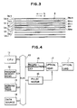
- Fig. 3 is an enlarged view of the main data recording portion M in Fig. 1.
- Optically detectable pits 4 are formed in the data tracks M n-3 to M n+1 when a light beam spot modulated in accordance with recording information is scanned on the optical card 1.
- the illumination position of the recording pit 4 must be controlled in a direction perpendicular to the scanning direction. For this purpose, there are tracking tracks T n-3 to T n+1 .
- Auto tracking (to be referred to as an AT hereinafter) is performed along the tracking track T n in a direction indicated by an arrow a so as to move the light beam modulated with the recording information, thereby recording the data in the data track M n .
- the move direction of the beam spot is then reversed, so that the beam is scanned in a direction indicated by an arrow b .
- the recorded data is reproduced and compared with the recording data, thus performing verification. If the verification result represents a normal operation, the V mark V n representing normal recording is recorded on a line extending from the data track M n .
- V mark V n is not recorded, and the recording cycle is shifted to the next track M n+1 .
- the same data is recorded in the track M n+1 , and the same verification as described above is performed.
- Fig. 4 is a block diagram showing a circuit arrangement of a data record-reproduction device for an optical card which employs the above data recording scheme. Recording of data into the optical card and reproduction of data therefrom are controlled by a microcomputer.
- a central processing unit (CPU) 11, a memory (ROM) 12 for storing programs, a working area (RAM) 13 including registers utilized for various operations under the control of the CPU 11, a data source 14 for storing recording data to be recorded in the optical card 1, a record-reproduction circuit 15, and a pulse motor 16 are connected to a bus 10.
- An optical head 17 is controlled by the record-reproduction circuit 15 and the pulse motor 16 and emits a light beam on the optical card 1 to record data therein or reproduce it therefrom.
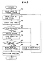
- Fig. 5 is a flow chart for recording a track number of the EOT in the EOT address area 3c of the directory D.
- step 50 the optical head 17 is moved to the leading track M1 of the main data recording portion M.
- step 51 data "1" is recorded in the track number area 2a of the data track M1, one-track data from the data source 14 is recorded in the data area 2b, and an error correction code is recorded in the ECC area 2c.
- step 52 the CPU 11 performs verification so as to check if the data is correctly recorded. If the data is not correctly recorded, NO is obtained in step 53, and the flow advances to step 54. However, if the data is correctly recorded, YES is obtained in. step 53. The V mark V1 is recorded in step 55, and the flow advances to step 56.
- step 56 the track number "1" of the track M1 recorded in step 51 is saved as a temporary EOT in the RAM 13.
- the CPU 11 determines in step 57 whether one-file data from the data source 14 is completely recorded. If NO in step 57, the flow advances to step 54. However, if YES in step 57, the flow advances to step 58.
- step 54 the optical head 17 is moved to the next track M2, and the same operations from step 51 are repeated until one-file data is completely recorded. For this reason, the contents of the RAM 13 are updated every time the operations are repeated.
- step 58 the optical head 17 is moved to the leading track D1 of the directory.
- step 59 predetermined data are respectively written in the areas 3a to 3d of the leading track D1 in accordance with the formats described above. In this case, the temporary EOT track number saved in the RAM 13 is recorded as an EOT address in the EOT address area 3c.
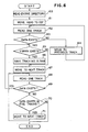
- Fig. 6 is a flow chart showing a method of detecting the EOT when the optical card is loaded in the record-reproduction device after the sequence in Fig. 5 is completed.
- step 60 the entire directory D of the card 1 is read.
- the file structure can be determined by reading the entire directory.
- step 61 the optical head 17 is moved by the pulse motor 16 to the EOT position recorded in the EOT address area 3c and representing the position of the last directory of the directories read in step 60.
- the detected EOT position is different from the true EOT position due to an error of the pulse motor 16, dimensional errors of the optical card 1, and an AT error.
- the directory of this data is not written. In this case, data is written after a track corresponding to the EOT track number written in the directory.
- the EOT stored in the directory is different from the actual EOT.
- the CPU 11 determines whether the EOT stored in the directory is the actual EOT. In this embodiment, when data are not continuously recorded in five consecutive tracks from the track M j recorded with data, this track is detected as an EOT track.
- step 62 AT is performed at the position of the optical head 17 to which it has been moved in step 61.
- One-track data is reproduced, and the V mark is detected.
- step 63 determines in step 63 whether the data is recorded in this data track. If YES in step 63, the flow advances to step 65 and the subsequent steps. However, if NO in step 63, the light beam spot is moved to the previous track in step 64. The operations are repeated from step 62.
- step 65 determines in step 65 whether the V mark is present in the reproduced data track. If YES in step 65, its track number is saved in the RAM 13 in step 66, and the flow advances to step 67. However, if NO in step 65, the flow jumps to step 67.
- step 67 the light beam spot is moved to the next data track, and data is reproduced from this data track in step 68.
- step 69 determines in step 69 whether data exists in this track. If YES in step 69, the same operations from step 65 are repeated. However, if NO in step 69, the flow advances to step 70.
- the CPU 11 determines in step 70 whether data exists in five tracks. If NO in step 70, the light beam spot is moved to the next track in step 71. The flow then returns to step 68, and the above operations are repeated until data exits in the five tracks.
- step 70 the track number saved in the RAM 13 is determined to be the EOT, thereby completing EOT detection.
- the optical head When data is added to the data tracks of the optical card, the optical head is moved to the track next to the EOT detected in this sequence. Data is additionally recorded in operations from step 51 in Fig. 5.
- the EOT position information is recorded in the directory to immediately search the last position of the recorded track from the EOT position information. Therefore, operations such as additional recording of the data and the like can be easily performed.
- the EOT is detected by detecting five nonrecorded tracks.
- the number of nonrecorded tracks can be arbitrarily determined in accordance with precision of the device and the like.
- the number of nonrecorded tracks is preferably 2 or more.
Abstract
Description
- The present invention relates to a method of recording data in a card-like optical recording medium (i.e., an optical card) or the like and, more particularly, to a method of recording data from an end track of a medium having a plurality of parallel tracks.
- A paper tape, a magnetic tape, and the like are popular as conventional recording media for sequentially recording data. When data is recorded in these recording media, an END mark, a field, or the like which represents an end of data at the end of recorded data is recorded to represent the end of the recorded data. In data reproduction, the END mark or the like is detected to detect the end of data.
- When additional data is recorded in such a recording medium, the end of the already recorded data must be detected. For example, an END mark is searched in, e.g., a magnetic tape to detect the end of data. From the position of the END mark, additional data is recorded and an END mark is recorded at the end of the additionally recorded data.
- However, in a large-capacity recording medium such as an optical card, a long period of time is required to search the last track (to be referred to as an EOT (End Of Track) recorded with data since detection is performed from the beginning of the tape. When additional data is to be written from the EOT, detection of the EOT is inevitable since recording is started from the track next to the EOT. In a system wherein a card is frequency loaded in or unloaded from a record-reproduction device, the EOT must be detected whenever the card is loaded therein or unloaded therefrom, thus prolonging the processing time.
- It is an object of the present invention to solve the conventional problems described above and to provide a method of quickly searching a last position of the previously recorded data when data are sequentially recorded in a medium.
- In order to achieve the above object of the present invention, there is provided a method of recording data, comprising the steps of: sequentially recording a series of data from a track on one side of a medium; writing index information including position information of a last track when the series of data are completely recorded in an area of the medium different from the area storing the data; reading out the position information and seeking the last track on the basis of the written position information; and recording the next data from a track next to the sought last track.
-
- Fig. 1 is a schematic plan view showing an optical card used in the present invention;
- Figs. 2A and 2B are schematic views respectively showing recording formats of a data track and a directory according to the present invention;
- Fig. 3 is an enlarged view of a data recorded portion of the optical card shown in Fig. 1;
- Fig. 4 is a block diagram showing an arrangement of a data record-reproduction device for practicing the method of the present invention; and
- Figs. 5 and 6 are flow charts for explaining operations according to the method of the present invention.
- Fig. 1 is a schematic plan view of an optical card used in a method of recording data according to the present invention.
- Referring to Fig. 1, a main data recording portion M consisting of data tracks M₁ to Mn and an auxiliary data recording portion D consisting of directories D₁ to D₅ recorded with index data for controlling the data files are formed on an
optical card 1. Verify marks (to be referred to as V marks hereinafter) V₁ to Vn are respectively formed on lines extending from the data tracks M₁ to Mn to represent that the data are normally recorded. - Data are recorded in the data tracks M₁ to Mn of the main data recording portion M one by one downward from the uppermost track in Fig. 1. The directories D₁ to Dn of the auxiliary data recording portion D are designed such that five directories can be recorded in one track in this embodiment. The directories are recorded from the left to the right in one track. When the five directories are recorded, a recording cycle is shifted to the upper track, so that the directories are sequentially recorded to the upper tracks. Figs. 2A and 2B show data formats of a data track Mj (j = 1 to n) and a directory Dj in Fig. 1.
- Referring to Fig. 2A, a track number area 2a is an area for recording the address number of this data track. The address number "1" is written for the data track M₁, the address number "2" is written for the data track M₂, and so on. A
data area 2b is an area for recording main data. AnECC area 2c is an area for recording an error correction code. - Referring to Fig. 2B, a
directory number area 3a is an area for recording a directory serial number. The directory serial number "1" is written for the directory D₁, "2", for the directory D₂, and so on. Adirectory area 3b is an area for recording contents of a series of data (i.e., a file), e.g., a file name, a data, and a file size. AnEOT address area 3c is an area for recording an address number of a track of the EOT of the main recording portion M. AnECC area 3d is an area for recording an error correction code. - Fig. 3 is an enlarged view of the main data recording portion M in Fig. 1. Optically
detectable pits 4 are formed in the data tracks Mn-3 to Mn+1 when a light beam spot modulated in accordance with recording information is scanned on theoptical card 1. In order to accurately record or reproduce thisrecording pit 4, the illumination position of therecording pit 4 must be controlled in a direction perpendicular to the scanning direction. For this purpose, there are tracking tracks Tn-3 to Tn+1. - A method of recording data in the main data recording portion will be briefly described with reference to Fig. 3.
- Auto tracking (to be referred to as an AT hereinafter) is performed along the tracking track Tn in a direction indicated by an arrow a so as to move the light beam modulated with the recording information, thereby recording the data in the data track Mn. When one-track data is completely recorded, the move direction of the beam spot is then reversed, so that the beam is scanned in a direction indicated by an arrow b. The recorded data is reproduced and compared with the recording data, thus performing verification. If the verification result represents a normal operation, the V mark Vn representing normal recording is recorded on a line extending from the data track Mn. However, if normal recording cannot be performed due to a defect of the optical card and an error occurs during verification, the V mark Vn is not recorded, and the recording cycle is shifted to the next track Mn+1. The same data is recorded in the track Mn+1, and the same verification as described above is performed.
- Fig. 4 is a block diagram showing a circuit arrangement of a data record-reproduction device for an optical card which employs the above data recording scheme. Recording of data into the optical card and reproduction of data therefrom are controlled by a microcomputer.
- A central processing unit (CPU) 11, a memory (ROM) 12 for storing programs, a working area (RAM) 13 including registers utilized for various operations under the control of the CPU 11, a
data source 14 for storing recording data to be recorded in theoptical card 1, a record-reproduction circuit 15, and apulse motor 16 are connected to a bus 10. - An
optical head 17 is controlled by the record-reproduction circuit 15 and thepulse motor 16 and emits a light beam on theoptical card 1 to record data therein or reproduce it therefrom. - The operations of the record-reproduction device will be described with reference to Figs. 5 and 6.
- Fig. 5 is a flow chart for recording a track number of the EOT in the
EOT address area 3c of the directory D. - A sequence for writing data in a blank
optical card 1 will be described. - When a new
optical card 1 is loaded in the record-reproduction device showin in Fig. 4, instep 50, theoptical head 17 is moved to the leading track M₁ of the main data recording portion M. - In
step 51, data "1" is recorded in the track number area 2a of the data track M₁, one-track data from thedata source 14 is recorded in thedata area 2b, and an error correction code is recorded in theECC area 2c. - In
step 52, the CPU 11 performs verification so as to check if the data is correctly recorded. If the data is not correctly recorded, NO is obtained instep 53, and the flow advances tostep 54. However, if the data is correctly recorded, YES is obtained in.step 53. The V mark V₁ is recorded instep 55, and the flow advances tostep 56. - In
step 56, the track number "1" of the track M₁ recorded instep 51 is saved as a temporary EOT in theRAM 13. - The CPU 11 determines in
step 57 whether one-file data from thedata source 14 is completely recorded. If NO instep 57, the flow advances to step 54. However, if YES instep 57, the flow advances to step 58. - In
step 54, theoptical head 17 is moved to the next track M₂, and the same operations fromstep 51 are repeated until one-file data is completely recorded. For this reason, the contents of theRAM 13 are updated every time the operations are repeated. - When one-file data recording is finished, the flow advances to step 58. In
step 58, theoptical head 17 is moved to the leading track D₁ of the directory. Instep 59, predetermined data are respectively written in theareas 3a to 3d of the leading track D₁ in accordance with the formats described above. In this case, the temporary EOT track number saved in theRAM 13 is recorded as an EOT address in theEOT address area 3c. - Fig. 6 is a flow chart showing a method of detecting the EOT when the optical card is loaded in the record-reproduction device after the sequence in Fig. 5 is completed.
- In
step 60, the entire directory D of thecard 1 is read. In a system for controlling the files in accordance with the directory information, the file structure can be determined by reading the entire directory. - In
step 61, theoptical head 17 is moved by thepulse motor 16 to the EOT position recorded in theEOT address area 3c and representing the position of the last directory of the directories read instep 60. In this case, the detected EOT position is different from the true EOT position due to an error of thepulse motor 16, dimensional errors of theoptical card 1, and an AT error. - When data recording is interrupted before completion due to an operation failure of a data recording device, the directory of this data is not written. In this case, data is written after a track corresponding to the EOT track number written in the directory. The EOT stored in the directory is different from the actual EOT. In order to prevent this drawback, from
step 62, the CPU 11 determines whether the EOT stored in the directory is the actual EOT. In this embodiment, when data are not continuously recorded in five consecutive tracks from the track Mj recorded with data, this track is detected as an EOT track. - More specifically, in
step 62, AT is performed at the position of theoptical head 17 to which it has been moved instep 61. One-track data is reproduced, and the V mark is detected. - The CPU 11 determines in
step 63 whether the data is recorded in this data track. If YES instep 63, the flow advances to step 65 and the subsequent steps. However, if NO instep 63, the light beam spot is moved to the previous track instep 64. The operations are repeated fromstep 62. - The CPU 11 determines in
step 65 whether the V mark is present in the reproduced data track. If YES instep 65, its track number is saved in theRAM 13 instep 66, and the flow advances to step 67. However, if NO instep 65, the flow jumps to step 67. - In
step 67, the light beam spot is moved to the next data track, and data is reproduced from this data track instep 68. - The CPU 11 determines in
step 69 whether data exists in this track. If YES instep 69, the same operations fromstep 65 are repeated. However, if NO instep 69, the flow advances to step 70. The CPU 11 determines instep 70 whether data exists in five tracks. If NO instep 70, the light beam spot is moved to the next track instep 71. The flow then returns to step 68, and the above operations are repeated until data exits in the five tracks. - However, if YES in
step 70, the track number saved in theRAM 13 is determined to be the EOT, thereby completing EOT detection. - When data is added to the data tracks of the optical card, the optical head is moved to the track next to the EOT detected in this sequence. Data is additionally recorded in operations from
step 51 in Fig. 5. - According to the present invention as has been described above, the EOT position information is recorded in the directory to immediately search the last position of the recorded track from the EOT position information. Therefore, operations such as additional recording of the data and the like can be easily performed.
- The present invention is not limited to the particular embodiment described above. Various changes and modifications may be made within the spirit and scope of the invention. In the above embodiment, the EOT is detected by detecting five nonrecorded tracks. However, the number of nonrecorded tracks can be arbitrarily determined in accordance with precision of the device and the like. When formation of a nonrecorded track in the recorded area by recording errors is taken into consideration, the number of nonrecorded tracks is preferably 2 or more.
- The present invention includes such changes and modifications without departing from the scope of the appended claims.
Claims (9)
sequentially recording a series of data from a track on one side of a medium;
writing index information including position information of a last recorded track, after the series of data are completely recorded, in an area of the medium different from the area where the data is recorded;
reading out the position information and seeking the last track on the basis of the readout position information; and
recording the next data from a track next to the sought last track.
Applications Claiming Priority (4)
| Application Number | Priority Date | Filing Date | Title |
|---|---|---|---|
| JP199166/87 | 1987-08-11 | ||
| JP199167/87 | 1987-08-11 | ||
| JP62199166A JPH0787004B2 (en) | 1987-08-11 | 1987-08-11 | Data recording method |
| JP19916787A JPS6443856A (en) | 1987-08-11 | 1987-08-11 | Data recording system |
Publications (2)
| Publication Number | Publication Date |
|---|---|
| EP0303377A1 true EP0303377A1 (en) | 1989-02-15 |
| EP0303377B1 EP0303377B1 (en) | 1992-05-20 |
Family
ID=26511376
Family Applications (1)
| Application Number | Title | Priority Date | Filing Date |
|---|---|---|---|
| EP88307045A Expired EP0303377B1 (en) | 1987-08-11 | 1988-07-29 | Method of recording position information of last track recorded with data in directory area |
Country Status (4)
| Country | Link |
|---|---|
| US (1) | US4982074A (en) |
| EP (1) | EP0303377B1 (en) |
| CA (1) | CA1313710C (en) |
| DE (1) | DE3871281D1 (en) |
Cited By (5)
| Publication number | Priority date | Publication date | Assignee | Title |
|---|---|---|---|---|
| EP0355620A2 (en) * | 1988-08-18 | 1990-02-28 | Omron Tateisi Electronics Co. | Optical card |
| EP0532356A2 (en) * | 1991-09-13 | 1993-03-17 | Canon Kabushiki Kaisha | Method of recording data and information regarding defects |
| EP0572216A2 (en) * | 1992-05-27 | 1993-12-01 | Canon Kabushiki Kaisha | Method for recording a plurality of kinds of data on recording medium and for reproducing the recorded data |
| EP0652564A1 (en) * | 1993-11-05 | 1995-05-10 | Canon Kabushiki Kaisha | Information recording method |
| AT404696B (en) * | 1994-03-16 | 1999-01-25 | Landis & Gyr Business Support | Information medium with heat-sensitive lattice structures |
Families Citing this family (13)
| Publication number | Priority date | Publication date | Assignee | Title |
|---|---|---|---|---|
| JP2796829B2 (en) * | 1989-03-28 | 1998-09-10 | キヤノン株式会社 | Information recording device |
| US5235172A (en) * | 1989-06-28 | 1993-08-10 | Harald Oehlmann | Method of reading a data carrier including multiple rows of bar code |
| US5288982A (en) * | 1990-06-11 | 1994-02-22 | Canon Kabushika Kaisha | Method for changing a file name of a directory in a non-rewritable record medium |
| US5239382A (en) * | 1990-08-02 | 1993-08-24 | Olympus Optical Co., Ltd. | Image sensing apparatus and recording/reproducing method thereof |
| US5390027A (en) * | 1990-08-23 | 1995-02-14 | Matsushita Electric Industrial Co., Ltd. | Television program recording and reproducing system using program data of text broadcast signal |
| JPH04141867A (en) * | 1990-10-03 | 1992-05-15 | Canon Inc | File managing method |
| US5408330A (en) * | 1991-03-25 | 1995-04-18 | Crimtec Corporation | Video incident capture system |
| US6091884A (en) * | 1991-08-19 | 2000-07-18 | Index Systems, Inc. | Enhancing operations of video tape cassette players |
| US6487362B1 (en) | 1991-08-19 | 2002-11-26 | Index Systems, Inc. | Enhancing operations of video tape cassette players |
| JPH0684187A (en) * | 1992-09-02 | 1994-03-25 | Olympus Optical Co Ltd | Information recording/reproduction method of worm-type information recording medium |
| US5481103A (en) * | 1994-07-26 | 1996-01-02 | Metanetics Corporation | Packet bar code with data sequence encoded in address/data packets |
| US5940853A (en) * | 1996-02-23 | 1999-08-17 | Matsushita Electric Industrial Co., Ltd. | Recording and reproducing apparatus enabling modification of data recorded on a non-erasable recording medium |
| TW375736B (en) * | 1997-07-15 | 1999-12-01 | Matsushita Electric Ind Co Ltd | Optical disk recording method, recording device, playback method and playback device |
Citations (3)
| Publication number | Priority date | Publication date | Assignee | Title |
|---|---|---|---|---|
| DE3545996A1 (en) * | 1984-12-26 | 1986-07-03 | Canon K.K., Tokio/Tokyo | RECORDING CARRIER FOR OPTICAL INFORMATION AND DEVICE FOR RECORDING AND PLAYING BACK INFORMATION USING THE SAME |
| EP0227380A1 (en) * | 1985-12-11 | 1987-07-01 | Canon Kabushiki Kaisha | Information recording medium and process for reproducing information therefrom |
| EP0251666A2 (en) * | 1986-06-23 | 1988-01-07 | Canon Kabushiki Kaisha | Apparatus for recording and reproducing information |
Family Cites Families (11)
| Publication number | Priority date | Publication date | Assignee | Title |
|---|---|---|---|---|
| JPS5832236A (en) * | 1981-08-18 | 1983-02-25 | Matsushita Electric Ind Co Ltd | Optical recorder and reproducer |
| JPS58181163A (en) * | 1982-04-16 | 1983-10-22 | Hitachi Ltd | Controlling system of storage device |
| US4791622A (en) * | 1983-09-19 | 1988-12-13 | Storage Technology Partners 11 | Optical data format employing resynchronizable data sectors |
| JPH0823969B2 (en) * | 1984-01-11 | 1996-03-06 | キヤノン株式会社 | Record confirmation device |
| JPS61240408A (en) * | 1985-04-17 | 1986-10-25 | Canon Inc | Recognising method for record information |
| JP2635023B2 (en) * | 1985-05-02 | 1997-07-30 | 株式会社日立製作所 | Label writing method for file data |
| JPH0636266B2 (en) * | 1985-10-18 | 1994-05-11 | キヤノン株式会社 | Information recording / reproducing device |
| JPH0782420B2 (en) * | 1985-12-04 | 1995-09-06 | キヤノン株式会社 | Information storage device |
| JPH0766312B2 (en) * | 1985-12-04 | 1995-07-19 | キヤノン株式会社 | Information storage device |
| JPS62131319A (en) * | 1985-12-04 | 1987-06-13 | Canon Inc | Information storage device |
| US4730293A (en) * | 1986-09-15 | 1988-03-08 | Drexler Technology Corporation | Dual beam optical data system |
-
1988
- 1988-07-29 US US07/225,825 patent/US4982074A/en not_active Expired - Lifetime
- 1988-07-29 DE DE8888307045T patent/DE3871281D1/en not_active Expired - Lifetime
- 1988-07-29 EP EP88307045A patent/EP0303377B1/en not_active Expired
- 1988-07-29 CA CA000573472A patent/CA1313710C/en not_active Expired - Fee Related
Patent Citations (3)
| Publication number | Priority date | Publication date | Assignee | Title |
|---|---|---|---|---|
| DE3545996A1 (en) * | 1984-12-26 | 1986-07-03 | Canon K.K., Tokio/Tokyo | RECORDING CARRIER FOR OPTICAL INFORMATION AND DEVICE FOR RECORDING AND PLAYING BACK INFORMATION USING THE SAME |
| EP0227380A1 (en) * | 1985-12-11 | 1987-07-01 | Canon Kabushiki Kaisha | Information recording medium and process for reproducing information therefrom |
| EP0251666A2 (en) * | 1986-06-23 | 1988-01-07 | Canon Kabushiki Kaisha | Apparatus for recording and reproducing information |
Cited By (11)
| Publication number | Priority date | Publication date | Assignee | Title |
|---|---|---|---|---|
| EP0355620A2 (en) * | 1988-08-18 | 1990-02-28 | Omron Tateisi Electronics Co. | Optical card |
| EP0355620A3 (en) * | 1988-08-18 | 1992-01-02 | Omron Tateisi Electronics Co. | Optical card |
| EP0532356A2 (en) * | 1991-09-13 | 1993-03-17 | Canon Kabushiki Kaisha | Method of recording data and information regarding defects |
| EP0532356A3 (en) * | 1991-09-13 | 1994-01-05 | Canon Kk | |
| US5442614A (en) * | 1991-09-13 | 1995-08-15 | Canon Kabushiki Kaisha | Method of recording data and information regarding defects |
| EP0572216A2 (en) * | 1992-05-27 | 1993-12-01 | Canon Kabushiki Kaisha | Method for recording a plurality of kinds of data on recording medium and for reproducing the recorded data |
| EP0572216A3 (en) * | 1992-05-27 | 1994-08-31 | Canon Kk | |
| US5488718A (en) * | 1992-05-27 | 1996-01-30 | Canon Kabushiki Kaisha | Recording and reproducing method in which data and updating data are recorded in a sector of a selected block of a recording medium in a predetermined order without recording a directory |
| EP0652564A1 (en) * | 1993-11-05 | 1995-05-10 | Canon Kabushiki Kaisha | Information recording method |
| US5739519A (en) * | 1993-11-05 | 1998-04-14 | Canon Kabushiki Kaisha | Information recording method |
| AT404696B (en) * | 1994-03-16 | 1999-01-25 | Landis & Gyr Business Support | Information medium with heat-sensitive lattice structures |
Also Published As
| Publication number | Publication date |
|---|---|
| EP0303377B1 (en) | 1992-05-20 |
| DE3871281D1 (en) | 1992-06-25 |
| US4982074A (en) | 1991-01-01 |
| CA1313710C (en) | 1993-02-16 |
Similar Documents
| Publication | Publication Date | Title |
|---|---|---|
| EP0303377B1 (en) | Method of recording position information of last track recorded with data in directory area | |
| US4984230A (en) | Rewritable optical disk with defective-sector substitution arrangement and optical information recording and reproducing system | |
| EP0584504B1 (en) | Tape format detection system | |
| EP0302119B1 (en) | Method for recording and reproducing data for an optical card | |
| US5442614A (en) | Method of recording data and information regarding defects | |
| EP0243503A1 (en) | Data recording/regenerating device | |
| US4937804A (en) | Apparatus for recording data into optical recording medium | |
| CA1294044C (en) | Apparatus for recording and reproducing information | |
| EP0261918B1 (en) | Method of recording indicia for indicating presence or absence of error in medium after error checking and apparatus therefor | |
| US5739519A (en) | Information recording method | |
| JPS61243994A (en) | Information recording method | |
| EP0323227A2 (en) | Information recording-reproducing method and apparatus | |
| EP0559468A2 (en) | Information recording method and apparatus | |
| JP2894633B2 (en) | Optical recording / reproducing device | |
| US5392267A (en) | Optical card reading and writing method with redundant directory storage to improve reliability | |
| JP2542419B2 (en) | Data recording method | |
| JPH0787004B2 (en) | Data recording method | |
| JP2860956B2 (en) | Optical card recording method | |
| JPH0498656A (en) | Discriminating method for track format | |
| JP2601615B2 (en) | Information recording method | |
| JPH0887437A (en) | Information recording method | |
| JPH09106629A (en) | Optical memory apparatus | |
| JPH08221905A (en) | Information recording and reproducing method and device therefor | |
| JPH01267885A (en) | Data retrieval system and information recording and reproducing device | |
| JPS63183664A (en) | Information recording and reproducing device |
Legal Events
| Date | Code | Title | Description |
|---|---|---|---|
| PUAI | Public reference made under article 153(3) epc to a published international application that has entered the european phase |
Free format text: ORIGINAL CODE: 0009012 |
|
| AK | Designated contracting states |
Kind code of ref document: A1 Designated state(s): DE FR GB IT NL |
|
| 17P | Request for examination filed |
Effective date: 19890713 |
|
| 17Q | First examination report despatched |
Effective date: 19901114 |
|
| GRAA | (expected) grant |
Free format text: ORIGINAL CODE: 0009210 |
|
| AK | Designated contracting states |
Kind code of ref document: B1 Designated state(s): DE FR GB IT NL |
|
| REF | Corresponds to: |
Ref document number: 3871281 Country of ref document: DE Date of ref document: 19920625 |
|
| ET | Fr: translation filed | ||
| ITF | It: translation for a ep patent filed |
Owner name: SOCIETA' ITALIANA BREVETTI S.P.A. |
|
| PLBE | No opposition filed within time limit |
Free format text: ORIGINAL CODE: 0009261 |
|
| STAA | Information on the status of an ep patent application or granted ep patent |
Free format text: STATUS: NO OPPOSITION FILED WITHIN TIME LIMIT |
|
| 26N | No opposition filed | ||
| REG | Reference to a national code |
Ref country code: GB Ref legal event code: IF02 |
|
| PGFP | Annual fee paid to national office [announced via postgrant information from national office to epo] |
Ref country code: GB Payment date: 20030715 Year of fee payment: 16 |
|
| PGFP | Annual fee paid to national office [announced via postgrant information from national office to epo] |
Ref country code: FR Payment date: 20030721 Year of fee payment: 16 |
|
| PGFP | Annual fee paid to national office [announced via postgrant information from national office to epo] |
Ref country code: DE Payment date: 20030723 Year of fee payment: 16 |
|
| PGFP | Annual fee paid to national office [announced via postgrant information from national office to epo] |
Ref country code: NL Payment date: 20030731 Year of fee payment: 16 |
|
| PG25 | Lapsed in a contracting state [announced via postgrant information from national office to epo] |
Ref country code: GB Free format text: LAPSE BECAUSE OF NON-PAYMENT OF DUE FEES Effective date: 20040729 |
|
| PG25 | Lapsed in a contracting state [announced via postgrant information from national office to epo] |
Ref country code: NL Free format text: LAPSE BECAUSE OF NON-PAYMENT OF DUE FEES Effective date: 20050201 Ref country code: DE Free format text: LAPSE BECAUSE OF NON-PAYMENT OF DUE FEES Effective date: 20050201 |
|
| GBPC | Gb: european patent ceased through non-payment of renewal fee |
Effective date: 20040729 |
|
| PG25 | Lapsed in a contracting state [announced via postgrant information from national office to epo] |
Ref country code: FR Free format text: LAPSE BECAUSE OF NON-PAYMENT OF DUE FEES Effective date: 20050331 |
|
| NLV4 | Nl: lapsed or anulled due to non-payment of the annual fee |
Effective date: 20050201 |
|
| REG | Reference to a national code |
Ref country code: FR Ref legal event code: ST |
|
| PG25 | Lapsed in a contracting state [announced via postgrant information from national office to epo] |
Ref country code: IT Free format text: LAPSE BECAUSE OF NON-PAYMENT OF DUE FEES;WARNING: LAPSES OF ITALIAN PATENTS WITH EFFECTIVE DATE BEFORE 2007 MAY HAVE OCCURRED AT ANY TIME BEFORE 2007. THE CORRECT EFFECTIVE DATE MAY BE DIFFERENT FROM THE ONE RECORDED. Effective date: 20050729 |