EP0306989B1 - 3D dimensioning in computer aided drafting - Google Patents
3D dimensioning in computer aided drafting Download PDFInfo
- Publication number
- EP0306989B1 EP0306989B1 EP88114824A EP88114824A EP0306989B1 EP 0306989 B1 EP0306989 B1 EP 0306989B1 EP 88114824 A EP88114824 A EP 88114824A EP 88114824 A EP88114824 A EP 88114824A EP 0306989 B1 EP0306989 B1 EP 0306989B1
- Authority
- EP
- European Patent Office
- Prior art keywords
- dimension
- plane
- vertex
- line
- extension
- Prior art date
- Legal status (The legal status is an assumption and is not a legal conclusion. Google has not performed a legal analysis and makes no representation as to the accuracy of the status listed.)
- Expired - Lifetime
Links
Images


Classifications
-
- G—PHYSICS
- G06—COMPUTING; CALCULATING OR COUNTING
- G06T—IMAGE DATA PROCESSING OR GENERATION, IN GENERAL
- G06T19/00—Manipulating 3D models or images for computer graphics
-
- G—PHYSICS
- G06—COMPUTING; CALCULATING OR COUNTING
- G06T—IMAGE DATA PROCESSING OR GENERATION, IN GENERAL
- G06T17/00—Three dimensional [3D] modelling, e.g. data description of 3D objects
- G06T17/10—Constructive solid geometry [CSG] using solid primitives, e.g. cylinders, cubes
-
- G—PHYSICS
- G06—COMPUTING; CALCULATING OR COUNTING
- G06T—IMAGE DATA PROCESSING OR GENERATION, IN GENERAL
- G06T2219/00—Indexing scheme for manipulating 3D models or images for computer graphics
- G06T2219/012—Dimensioning, tolerancing
Definitions
- the present invention generally relates to computer aided drafting (CAD) systems and, more particularly, to a procedure which permits the addition of dimensions to three dimensional (3D) computer models without the necessity of two models and also permits automatic documentation.
- CAD computer aided drafting
- a solid model can be viewed so as to produce a standard drawing view, i.e. a principal, cross section, auxilliary or detail view, in which case it is desirable for the dimensions to follow the standards for dimensions on a drawing as set forth, for example, in "Dimensioning and Tolerancing", American National Standard Y14.5 from American Society of Mechanical Engineers, 345 East 47th Street, New York, NY 10 ⁇ 0 ⁇ 17.
- a solid model also can be viewed so as to produce any axonometric, e.g. isometric, view but these views in traditional drawings are not often dimensioned.
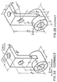
- Baseline dimensions can be used as shown on the bottom of Figure 5. If the viewpoint is rotated and the dimensions are restricted to be in a single plane, the dimensions may appear as shown at the bottom of Figure 6. very misleading since the left extension lines of the two longer dimensions are pointing to incorrect vertices.
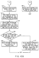
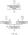
- FIGS. 10 ⁇ A and 10 ⁇ B show a detailed flow chart of the procedure according to the invention.
- the local coordinate system u,v,w is oriented so that the w direction gives the desired normal for dimensions and u is in the desired direction as indicated in function block 110 ⁇ .
- a test is then made in decision block 111 to determine if a linear dimension is being entered. Assuming for the time being that a linear dimension is being entered, the user specifies two vertices on the object (or, as will be discussed subsequently, edges, circles and arcs) as indicated in function block 112. In function block 113, the first vertex and the w direction determine the plane of the dimension.
- a test is next made in decision block 114 to determine if the second vertex is in the plane of the dimension. If not, a test is next made in decision block 115 to determine if the display is being created for a drawing as opposed to the model. If so, then a call is made in function block 116 to the procedure in Figure 11, described in more detail hereinafter. At this point, the vertices may be changed from those that the user entered.
- a test is next made in decision block 117 to determine if the second vertex is in the plane of the dimension. If so, control passes to function block 118 which is the same result that would obtain if the test in decision block 114 had been positive. Otherwise, control passes to function block 119, and this is the-same result that would obtain if the test in decision block 115 had been negative.
- function block 118 the second extension line is drawn in the plane of the dimension.
- function block 119 a break is made in the second extension line.
- the dimensioned edges are projected onto the uv plane. The point at which the extensions of these projections cross is also on the axis of the cylinder. The user supplied level determines the radius of the cylinder.
- function block 123 the point at which an extension of the first dimensioned edge intersects the cylinder is found. The plane of the dimension will pass through that point and will be perpendicular to the w axis.
- the first extension line is drawn parallel to the first dimension edge, then the dimension line, arrowheads and text are drawn in the dimension plane.
- a test is then made in decision block 125 to determine if the intersection of an extension of the second dimension line and the cylinder is in the dimension plane. If it is, a second extension line is built parallel to the second edge in function block 126 and the procedure exits. Otherwise, a second extension line is built parallel to the second edge with a break parallel to w half way between the arrow end of the line and the vertex, as indicated in function block 127 and, again, the procedure exits.
- the dimension is assumed to be a radius or diameter dimension as indicated in function block 128. This type of dimension is drawn in function block 128 with no breaks and the procedure exits.
- FIG. 11A, 11B and 11C a generalized procedure is shown for determining whether a broken extension line is required for the second end of a dimension.
- the procedure begins with decision block 130 ⁇ which determines whether the second end of the dimension is an edge. If not, a reference is made through the vertices of the model in function block 131 and, in decision block 132, a determination is made as to whether vertex B at the second end of the dimension projects onto the model vertex R. More specifically, if R is transformed into the coordinate system of the dimension, u, v and w, and it differs from B in only its w coordinate, then R projects into B.
- the test is positive; i.e., the second end of the dimension is at an edge.
- a search is made through the edges of the model in function block 139 and, in decision block 140 ⁇ , a test is made to determine if the edge MN is equivalent to the second edge CD.
- a normal dimension can be perpendicular to an edge. In this case, the edge is straight and in the plane of that end of the dimension. Assume a normal dimension which references edge CD at vertex C and CD is straight.
- an end of a linear dimension is to a circle, it is actually referenced to an edge which approximates that circle in a faceted solid modeling system. Edges which approximate a circle are tagged as curved edges.
- a linear dimension references edge CD and CD is curved
- MN must be from a circle which has the same radius and center, except for a difference in w.
- the most common case is moving a dimension from one end of a cylinder to the other. In this case, we can look for an equivalent edge, MN, to be one in which M projects onto C and N onto D or vice versa.
- decision block 140 ⁇ If the test is decision block 140 ⁇ is positive, then a test is made in decision block 141 to determine if the edge MN is in the plane of the first end. This is true if both vertices A and B are in the plane of the first end. If it is, the procedure jumps to Figure 11C and function block 134; otherwise, if the dimension is not a baseline dimension, the edge MN is put on the edge list as indicated in function block 142. The procedure is now at the same point that would obtain if the test in decision block 140 ⁇ were negative. At this point, a test is made in decision block 143 to determine if all the edges have been tested. If not, the procedure returns to function block 139; otherewise, the procedure goes to decision block 137.
- FIG. 11B where the procedure continues.
- a test is first made in decision block 144 to determine if the first end of the dimension is on an edge. If not, a search is made through the vertices of the model in function block 145 and then, in decision block 146, a determination is made as to whether the vertex at the first end of the dimension projects onto the model vertex R. If so, a test is made in decision block 147 to determine if R is in the plane of the second end of the dimension. If this test is positive, then the procedure jumps to Figure 11C where, in function block 148, the first end of the dimension is re-referenced and, as noted in fucntion block 149, a broken extension line is not required. At this point, the procedure exits.
- test in decision block 150 ⁇ is negative, the procedure arrives at the same point that would obtain if the test in decision block 146 were negative.
- a test is next made in decision block 152 to determine if all the vertices have been tested and, if not, the procedure returns to function block 145; otherwise, the procedure goes to function block 153 where a broken extension line is required. At this point, the procedure exits.
- a search is made through the edges of the model in function block 154 and, in decision block 155, a test is made to determine if the model edge MN is equivalent to the first edge. If it is, then a test is made in decision block 156 to determine if edge MN is in the plane of the second end of the dimension. If it is, the procedure jumps to function block 148 in Figure 11C; otherwise, a test is made in decision block 157 to determine if edge MN is in the plane of a vertex or edge on the list.
- the procedure according to the invention finds the plane through the first vertex and perpendicular to a unit vector, w, and checks to see if the other end of each dimension can be moved to an equivalent vertex on that plane.
- the procedure projects vertices of a given dimension onto other planes perpendicular to the vector, w, and tests to see if vertices exist for both ends of the dimension in those positions on any plane.
- An alternate method for handling the non-baseline case is to 1) find the plane through the first vertex and perpendicular to the vector, w, (if it exists) and see if the other end of the dimension can be moved to an equivalent vertex, 2) repeat for the second vertex, and 3) for each plane perpendicular to the vector, w, (except those already tested) see if vertices exist for both ends of the dimension.
- Figure 12 helps to visualize these operations.
- the vector, w is in the plane of the paper and is a unit vector.
- A be a vertex referenced by the dimension in question and O be the origin of the coordinate system.
- the inner product of vector A and unit vector w is m, the length of vector L, the projection of A onto w.
- m Aw
- the head of vector L is in the plane containing A and perpendicular to w.
- This plane has a normal equal to v and its d value equals m, so we can find if it exists in the model.
- This method also can be used to find the plane containing the other vertex of the dimension which is perpendicular to w, if it exists.
- the first thing that is done is to calculate the values of m for the vertices A and B as indicated by function block 160 ⁇ .
- decision block 161 a test is made to determine if there is a plane, Q, in the model which is perpendicular to the vector, w. Assuming initially that the test in decision block is positive, the vertex A is projected onto plane Q to produce J as indicated in function block 162. This is followed by a test in decision block 163 o determine if J is equal to a vertex on plane Q. If it is not, control returns to decision block 161; otherwise, a vertex has been found on plane Q and so vertex B is next projected onto plane Q to produce H as indicated in function block 164.
- decision block 165 determines if H is equal to a vertex in plane Q. If it is not, control returns to decision block 161; otherwise, vertices A and B are referenced to J and H in plane Q, and the procedure exists. Returning briefly to decision block 161, if there is no plane Q in the model which is perpendicular to the vector, w, then the procedure exits.
- 3D dimensions solve the baseline problem of Figure 6 for both linear and angular dimensions.
- the procedure described solves the problem of superimposed vertices for linear dimensions.
Description
- The present invention generally relates to computer aided drafting (CAD) systems and, more particularly, to a procedure which permits the addition of dimensions to three dimensional (3D) computer models without the necessity of two models and also permits automatic documentation.
- It is now possible to build solid models of parts in a general purpose computer. These models can be used to calculate properties of the parts, such as center of gravity and moments of inertia. They can also be used to test for interference between parts. Parts which are defined in a solid modeling system are not completely designed for manufacture until one adds dimensions and tolerances to the model. These dimensions and tolerances are traditionally included on the drawing of the part.
- From COMPUTER, vol. 15, no. 11, November 1982, pages 35-47, a computer aided drafting method for adding dimension and tolerance parameters to the representation of a three dimensional object being modelled in a computer is known. If a person indicates the line segments or points associated with the required dimensions, then the engineering drawing derived by projection from the geometric model can be produced, with appropriate dimensioning data attached at appropriate location, by the computer.
- Current practice is to make projections of the solid model and send these to a two dimensional (2D) drafting system, where dimensions and tolerances are added and a complete engineering drawing is produced. The major problem with this approach is that there are two models, the 3D solid model and the 2D drawing model. When numerous changes are in progress, it is difficult to keep these two models consistent. Therefore, it would be desirable to be able to add the dimensions and tolerances to the solid model and have only one model.
- Some tolerances, such as geometric forms, are parts of leaders and others are parts of dimensions on the drawing. In addition, there are usually default linear and angular tolerances in the title block of the drawing. If a dimension is shown on the drawing without a tolerance and is not declared basic or reference, then the appropriate title block tolerance applies. Since so many people are familiar with these conventions, it is desirable that a solid modeling system be consistent with them. Therefore, leaders and dimensions which can be applied to solid models are needed.
- It is therefore an object of this invention as claimed to provide a 3D dimensioning procedure for CAD systems in which there is but one model, the 3D solid model, and wherein dimensions and tolerances are added to the solid model.
- It is another object of the invention as claimed to provide a 3D dimensioning procedure for CAD systems that automatically supplies correct 2D leaders and dimensions when the solid model is viewed so as to produce a drawing.
- This object of the invention is accomplished by the features of claim 1. Further advantages of the invention are characterized in the subclaims.
- The foregoing and other objects, aspects and advantages of the invention will be better understood from the following detailed description of a preferred embodiment of the invention with reference to the drawings, in which:
- Figures 1A to 1F are illustrations taken from a drafting textbook illustrating various possible dimensioning of an isometric view;
- Figures 2A and 2B are illustrations taken from a drafting textbook illustrating problems in dimensioning a complex isometric view;
- Figures 3 and 4 are illustrations taken from a drafting textbook showing typical dimensioned axonometric views from which a student is to draw conventional plan views;
- Figure 5 is a plan view of a solid model showing the use of baseline or datum dimensions;
- Figure 6 is an axonometric view of the solid model shown in plan view in Figure 5 showing that the use of baseline or datum dimensions can be misleading;
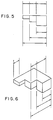
- Figures 7 and 8 are axonometric views of the solid model shown in plan view in Figure 5 illustrating the dimensioning process according to the present invention;
- Figure 9 is an axonometric view of a solid model showing how angular dimensioning is handled by the present invention;
- Figures 10̸A and 10̸B, taken together, are a flow chart of the procedure according to the invention;
- Figures 11A, 11B and 11C, taken together, are a flow chart of the generalization of details according to the invention;
- Figure 12 is vector drawing in three dimensional space which illustrates the operations according to the procedure of the present invention;
- Figure 13 is a flow chart showing the procedure called from the flow chart of Figures 10̸A and 10̸B; and
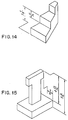
- Figures 14 and 15 are axonometric views of solid models dimensioned according to the procedure of the present invention.
- In order to better understand the invention, it is necessary to briefly review the conventions currently observed in dimensioning axonometric views of solid models. A solid model can be viewed so as to produce a standard drawing view, i.e. a principal, cross section, auxilliary or detail view, in which case it is desirable for the dimensions to follow the standards for dimensions on a drawing as set forth, for example, in "Dimensioning and Tolerancing", American National Standard Y14.5 from American Society of Mechanical Engineers, 345 East 47th Street, New York, NY 10̸0̸17. A solid model also can be viewed so as to produce any axonometric, e.g. isometric, view but these views in traditional drawings are not often dimensioned.
- In drafting textbooks, there are often a few pages devoted to describing dimensioning axonometric projections. Basically, conventional dimensions are used, but they are skewed to be parallel with the axes of the part. As one example, Figures 1A to 1F taken from the textbook Technical Drawing by F. E. Giesecke, A. Mitchell and H. C. Spencer, published by The Macmillan Co. of New York, show that dimensions should be drawn in the planes to which they apply. There are new pitfalls as shown in Figure 2B where the 3 1/8 dimension is incorrect because the dimension line and dimensioned points are not coplanar in 3D space.
- The greatest usage of dimensions on axonometric views seems to be found also in drafting textbooks. The author of a textbook may present the reader a dimensioned axonometric view and ask the reader to draw a conventional view. Such an example illustrates additional evidence of the increased difficulty of dimensioning in axonometric views. For example, in Figure 3 from the Giesecke et al textbook it can be seen that additional construction lines have been added to permit the use of conventional dimensions. In Figure 4, it will be observed that the 5 3/4 dimension is from a plane to an edge. This is confusing and would be troublesome to implement in a computerized system. These examples demonstrate that conventional dimensioning is not general enough to handle axonometric cases conventionally.
- There are additional problems introduced when one wishes to dimension a 3D model because the model and its associated dimensions can be viewed from any angle. The first problem occurs with baseline or datum dimensions. Baseline dimensions can be used as shown on the bottom of Figure 5. If the viewpoint is rotated and the dimensions are restricted to be in a single plane, the dimensions may appear as shown at the bottom of Figure 6. very misleading since the left extension lines of the two longer dimensions are pointing to incorrect vertices.
- A second problem occurs even in individual dimensions in this situation. In Figure 5, there are vertices directly behind one another, and the user does not care which one is used. However, when the part is viewed as in Figure 6, it does make a difference. If a convention is adopted that the dimension will be in a plane through the first vertex and parallel to the plane of the paper of Figure 5, then we may get dimensions as shown at the top of Figure 6. On a crowded drawing, these could be easily misinterpreted.
- The solution to the first problem is to generalize the conventional 2D dimensions to 3D dimensions. For a linear 3D dimension, we will permit an extension line to be broken and to extend out of the plane of the conventional 2D dimension as shown in Figure 7. Note that the baseline dimensions are now pointing to correct vertices and, if viewed along the indicated normal viewing direction, will appear as in Figure 5.
- This has also improved the second problem, because the non-baseline dimensions now also point to the correct vertices and, if viewed along the indicated normal viewing direction, will appear as in Figure 5. If the user entered the dimensions on the view of Figure 7, he would probably do a neater job, such as shown in Figure 8. A dimension in Figure 7 can be changed to its representation in Figure 8 by moving one or both extension lines to another vertex, which is equivalent along the normal viewing direction. The complete solution then involves a program that can find these equivalent vertices so the system can build dimensions without broken extension lines when possible.
- Similar problems exist for an angular dimension, as shown in Figure 9. There are cases, such as shown in Figure 9, where the lines to be dimensioned are not in the same plane (the box has been rotated about the dashed line 30̸ degrees up from the plane on which the prism rests). The broken extension line helps to relate the dimension to the upper extension line in the figure. A variation of this would be to draw the dimension on another plane parallel to the one shown in which case two broken extension lines may be required.
- Having described the invention in general terms, reference is now made to Figures 10̸A and 10̸B which show a detailed flow chart of the procedure according to the invention. To begin the procedure, the local coordinate system u,v,w is oriented so that the w direction gives the desired normal for dimensions and u is in the desired direction as indicated in function block 110̸. A test is then made in
decision block 111 to determine if a linear dimension is being entered. Assuming for the time being that a linear dimension is being entered, the user specifies two vertices on the object (or, as will be discussed subsequently, edges, circles and arcs) as indicated infunction block 112. Infunction block 113, the first vertex and the w direction determine the plane of the dimension. A test is next made indecision block 114 to determine if the second vertex is in the plane of the dimension. If not, a test is next made indecision block 115 to determine if the display is being created for a drawing as opposed to the model. If so, then a call is made infunction block 116 to the procedure in Figure 11, described in more detail hereinafter. At this point, the vertices may be changed from those that the user entered. A test is next made indecision block 117 to determine if the second vertex is in the plane of the dimension. If so, control passes to function block 118 which is the same result that would obtain if the test indecision block 114 had been positive. Otherwise, control passes to functionblock 119, and this is the-same result that would obtain if the test indecision block 115 had been negative. - In
function block 118, the second extension line is drawn in the plane of the dimension. Infunction block 119, a break is made in the second extension line. After the procedures of function blocks 118 or 119 have been performed, control passes to function block 120̸ where the first extension line, dimension line, arrowheads, and text are drawn in the plane of the dimension. - Returning to decision block 111, if a linear dimension is not being entered, then a test is made in
decision block 121 to determine if the dimension being entered is an angular or curve dimension such as shown in Figure 9. If so, the dimension line will be on a cylinder whose axis is parallel to the direction w. Infunction block 122, the dimensioned edges are projected onto the uv plane. The point at which the extensions of these projections cross is also on the axis of the cylinder. The user supplied level determines the radius of the cylinder. Next, infunction block 123, the point at which an extension of the first dimensioned edge intersects the cylinder is found. The plane of the dimension will pass through that point and will be perpendicular to the w axis. Infunction block 124, the first extension line is drawn parallel to the first dimension edge, then the dimension line, arrowheads and text are drawn in the dimension plane. A test is then made indecision block 125 to determine if the intersection of an extension of the second dimension line and the cylinder is in the dimension plane. If it is, a second extension line is built parallel to the second edge infunction block 126 and the procedure exits. Otherwise, a second extension line is built parallel to the second edge with a break parallel to w half way between the arrow end of the line and the vertex, as indicated infunction block 127 and, again, the procedure exits. - Assuming now that the test in
decision block 121 is negative, then the dimension is assumed to be a radius or diameter dimension as indicated infunction block 128. This type of dimension is drawn infunction block 128 with no breaks and the procedure exits. - The function referenced in
block 116 in Figure 10̸A will now be treated in greater detail. The purpose of the procedure according to the present invention is to identify vertices which will permit dimensions such as those of Figure 7 to be converted to those of Figure 8 automatically. At the time dimensions are entered a vector, W, such as the normal line of Figure 7 is defined in 3D by the user. Each dimension then entered must lie on a plane perpendicular to this vector. The first dimension vertex selected by the user determines that plane for that dimension. Therefore, in Figure 7, the broken extension line is associated with the second vertex selected. In order to put each dimension into a plane, for dimension I the first extension line must be moved, for dimension II the second extension line must be moved, and for dimension III both extension lines must be moved. - Referring now to Figures 11A, 11B and 11C, a generalized procedure is shown for determining whether a broken extension line is required for the second end of a dimension. The procedure begins with decision block 130̸ which determines whether the second end of the dimension is an edge. If not, a reference is made through the vertices of the model in
function block 131 and, indecision block 132, a determination is made as to whether vertex B at the second end of the dimension projects onto the model vertex R. More specifically, if R is transformed into the coordinate system of the dimension, u, v and w, and it differs from B in only its w coordinate, then R projects into B. There should be a tolerance on this test for numerical noise,ε , which can be 10̸-10̸ for a system with a precision of 12 digits or more. Then

Assuming that the test indecision block 132 is positive, a decision is next made indecision block 133 to determine if R is in the plane of the first end of the dimension. Points A and R are on the same w plane if


Assuming that R is found to be in the plane of the first end of the dimension, the procedure jumps to Figure 11C where infunction block 134 the second end of the dimension is re-referenced so that a broken extension line is not required. The procedure then exits. - Returning to decision block 133, if a determination is made that R is not in the plane of the first end of the dimension, then if not a baseline dimension, R is put on the vertex list in
function block 135. This point in the procedure is the same as would obtain if the test indecision block 132 is negative. A test is then made indecision block 136 as to whether all vertices have been tested. If not, the procedure returns to functionblock 131; otherwise, a test is made indecision block 137 as to whether the dimension is a baseline dimension. If it is, a broken extension line is required as indicated infunction block 138. At this point, the procedure exits. If the dimension is not a baseline dimension, the procedure jumps to Figure 11B which will be described in more detail hereinafter. - Returning now to decision block 130̸, assume now that the test is positive; i.e., the second end of the dimension is at an edge. In this case, a search is made through the edges of the model in
function block 139 and, in decision block 140̸, a test is made to determine if the edge MN is equivalent to the second edge CD. In addition to the linear dimensions which are referenced to vertices, it is possible to define a linear dimension to an edge. A normal dimension can be perpendicular to an edge. In this case, the edge is straight and in the plane of that end of the dimension. Assume a normal dimension which references edge CD at vertex C and CD is straight. Then, for an edge MN to be equivalent to CD, 1) either M or N must project onto C and 2) if it is M that projects onto C, then MN must have the same direction as CD, or if it is N that projects onto C, then NM must have the same direction as CD. An edge PQ has the same direction as CD if the dot product of their vectors is unity when each vector has unit magnitude:

- If an end of a linear dimension is to a circle, it is actually referenced to an edge which approximates that circle in a faceted solid modeling system. Edges which approximate a circle are tagged as curved edges. When a linear dimension references edge CD and CD is curved, then for an edge MN to be equivalent to CD, MN must be from a circle which has the same radius and center, except for a difference in w. The most common case is moving a dimension from one end of a cylinder to the other. In this case, we can look for an equivalent edge, MN, to be one in which M projects onto C and N onto D or vice versa.
- If the test is decision block 140̸ is positive, then a test is made in
decision block 141 to determine if the edge MN is in the plane of the first end. This is true if both vertices A and B are in the plane of the first end. If it is, the procedure jumps to Figure 11C andfunction block 134; otherwise, if the dimension is not a baseline dimension, the edge MN is put on the edge list as indicated infunction block 142. The procedure is now at the same point that would obtain if the test in decision block 140̸ were negative. At this point, a test is made indecision block 143 to determine if all the edges have been tested. If not, the procedure returns to functionblock 139; otherewise, the procedure goes todecision block 137. - At this point reference is made to Figure 11B where the procedure continues. A test is first made in
decision block 144 to determine if the first end of the dimension is on an edge. If not, a search is made through the vertices of the model infunction block 145 and then, indecision block 146, a determination is made as to whether the vertex at the first end of the dimension projects onto the model vertex R. If so, a test is made indecision block 147 to determine if R is in the plane of the second end of the dimension. If this test is positive, then the procedure jumps to Figure 11C where, infunction block 148, the first end of the dimension is re-referenced and, as noted infucntion block 149, a broken extension line is not required. At this point, the procedure exits. - Returning to decision block 147, if R is not in the plane of the second end of the dimension, then a test is made in decision block 150̸ to determine if R is in the plane of a vertex or edge in the list. If so, the procedure jumps to function
block 151 in Figure 11C where both ends of the dimension are re-referenced, and then the procedure goes to functionblock 149. - On the other hand, if the test in decision block 150̸ is negative, the procedure arrives at the same point that would obtain if the test in
decision block 146 were negative. A test is next made indecision block 152 to determine if all the vertices have been tested and, if not, the procedure returns to functionblock 145; otherwise, the procedure goes to function block 153 where a broken extension line is required. At this point, the procedure exits. - Returning to decision block 144, if the first end of the dimension is on an edge, then a search is made through the edges of the model in
function block 154 and, indecision block 155, a test is made to determine if the model edge MN is equivalent to the first edge. If it is, then a test is made indecision block 156 to determine if edge MN is in the plane of the second end of the dimension. If it is, the procedure jumps to functionblock 148 in Figure 11C; otherwise, a test is made in decision block 157 to determine if edge MN is in the plane of a vertex or edge on the list. If it is, the procedure jumps to functionblock 151 in Figure 11C; otherwise, a test is made indecision block 158 to determine if all the edges have been tested. If not, the procedure returns to functionblock 154; otherwise, then to function block 153 from which the procedure exits. - In the case of baseline dimensions, the procedure according to the invention finds the plane through the first vertex and perpendicular to a unit vector, w, and checks to see if the other end of each dimension can be moved to an equivalent vertex on that plane. For non-baseline dimensions, the procedure projects vertices of a given dimension onto other planes perpendicular to the vector, w, and tests to see if vertices exist for both ends of the dimension in those positions on any plane. An alternate method for handling the non-baseline case is to 1) find the plane through the first vertex and perpendicular to the vector, w, (if it exists) and see if the other end of the dimension can be moved to an equivalent vertex, 2) repeat for the second vertex, and 3) for each plane perpendicular to the vector, w, (except those already tested) see if vertices exist for both ends of the dimension.
- Variations from the general solution presented are possible. For example, the code would run faster if the user handled some of the exceptional cases manually. One option is to have the system try to project the second end of the dimension into the plane of the first and vice versa but not to try to project both ends into a third plane. Another option is to restrict the search to planes which exist in the model. This is described in Figures 12 and 13.
- Figure 12 helps to visualize these operations. In Figure 12, the vector, w, is in the plane of the paper and is a unit vector. Let A be a vertex referenced by the dimension in question and O be the origin of the coordinate system. Then the inner product of vector A and unit vector w is m, the length of vector L, the projection of A onto w.

The head of vector L is in the plane containing A and perpendicular to w. This plane has a normal equal to v and its d value equals m, so we can find if it exists in the model. This method also can be used to find the plane containing the other vertex of the dimension which is perpendicular to w, if it exists. - Now, let us deal with an arbitrary plane, Q, which is perpendicular to the vector, w. Let P be the plane through the origin which is perpendicular to w. If K is the projection of A onto P in the direction of w, then the signed length A-K is equal to that of L, namely m. The point K is then found as

If the origin is projected onto Q along w, the projection is dw, where d is the constant term in the definition of the plane Q. If J is the projection of A onto Q along the direction of W, then

and substituting for K from above,

To check for the equality of J with a vertex S on Q, we use a tolerance, t, to allow for numerical inaccuracies. If


function block 116 in Figure 10̸A. - With reference to Figure 13, the first thing that is done is to calculate the values of m for the vertices A and B as indicated by function block 160̸. Then, in
decision block 161, a test is made to determine if there is a plane, Q, in the model which is perpendicular to the vector, w. Assuming initially that the test in decision block is positive, the vertex A is projected onto plane Q to produce J as indicated infunction block 162. This is followed by a test in decision block 163 o determine if J is equal to a vertex on plane Q. If it is not, control returns to decision block 161; otherwise, a vertex has been found on plane Q and so vertex B is next projected onto plane Q to produce H as indicated infunction block 164. This in turn is followed by a test indecision block 165 to determine if H is equal to a vertex in plane Q. If it is not, control returns to decision block 161; otherwise, vertices A and B are referenced to J and H in plane Q, and the procedure exists. Returning briefly to decision block 161, if there is no plane Q in the model which is perpendicular to the vector, w, then the procedure exits. - The foregoing procedure makes it easy for the user to put dimensions in the planes of the object as shown in Figure 1. The 3 1/8 dimension of Figure 2 will become a 3D dimension with a broken extension line. Figure 14 shows how 3D dimensions can be used to avoid the extra construction lines of Figure 3, and Figure 15 shows that 3D dimensions can be used to avoid referencing linear dimensions to edges and surfaces as was done in Figure 4. It should be noted that there is a default position for the break in the extension lines so that the procedure for the entry of the dimension is unchanged by the fact that a 3D dimension may result.
- 3D dimensions solve the baseline problem of Figure 6 for both linear and angular dimensions. The procedure described solves the problem of superimposed vertices for linear dimensions. There is a corresponding problem of superimposed edges for angular dimensions which can be solved in a similar way.
Claims (7)
- A computer aided drafting method for adding dimension and tolerance parameters to the representation of a three dimensional object being modelled in a computer,
said method being characterized
in that said dimension and tolerance parameters are added to a three dimensional solid model of the object, whereby changes effected on the three dimensional model are reflected in the dimension and tolerance information automatically attached on the two-dimensional views of the object supplied by the system
and by comprising the steps of
obtaining (112) two user specified parameters on the object the first of which, together with a locally specified coordinate system, determines (113) the plane of a dimension, said parameters being a vertex, an edge, an arc or a circle;
if the second of said two parameters is in the plane of said dimension, drawing (118) an extension line from said second parameter in said plane and then drawing (120) an extension line from said first parameter, a dimension line with arrowheads and dimension text in said plane between said extension lines; but
if said second parameter is not in said plane, drawing (119) an extension line from said second parameter with a dogleg break and then drawing (120) an extension line from said first parameter a dimension line with arrowheads and dimension text in said plane between said extension lines. - The method according to claim 1, wherein said two user specified parameters are two user specified vertices.
- The computer aided drafting method according to claim 2 in the case where said second vertex is not in said plane and it is determined that the dimension is being created for a drawing as opposed to the model further comprising for baseline dimensions the steps of:
finding the plane through the first vertex of said two vertices and perpendicular to a unit vector, w, and determining if the other end of the dimension can be moved to an equivalent vertex on that plane;
and if so, determining (117) if the equivalent vertex is in the plane of the dimension, and if so drawing (118) an extension line from said equivalent vertex and then drawing (120) an extension line from said first vertex, a dimension line with arrowheads and dimension text between said extension lines, otherwise, drawing (119) an extension line from said second vertex with a dogleg break and then drawing (120) an extension line from said first vertex and a dimension line with arrowheads and dimension text between said extension lines. - The computer aided drafting method according to claim 3 in the case where said second vertex is not in said plane and it is determined that the dimension is being created for a drawing as opposed to the model further comprising for non-baseline dimensions the steps of:
determining if said vertices project parallel to said unit vector, w, onto other equivalent vertices in the model;
and determining if equivalent vertices exist for both ends of the dimension in those positions on the same plane perpendicular to w;
and if so, determining (117) if the second vertex is in the plane of the dimension, and if so drawing (118) an extension line from said equivalent vertex and then drawing (120) an extension line from said first vertex and a dimension line with arrowheads and dimension text between said extension lines, otherwise, drawing (119) an extension line from said second vertex with a dogleg break and then drawing (120) an extension line from said first vertex and a dimension line with arrowheads and dimension text between said extension lines. - The computer aided drafting method according to claim 3 in the case where said second vertex is not in said plane and it is determined that the dimension is being created for a drawing as opposed to the model further comprising for non-baseline dimensions the steps of:
projecting said vertices onto other planes perpendicular to said unit vector, w, and determining if vertices exist for both ends of the dimension in those positions on any plane;
and if so, determining (117) if the second vertex is in the plane of the dimension, and if so drawing (118) an extension line from said equivalent vertex and then drawing (120) an extension line from said first vertex and a dimension line with arrowheads and dimension text between said extension lines, otherwise, drawing (119) an extension line from said second vertex with a dogleg break and then drawing (120) an extension line from said first vertex and a dimension line with arrowheads and dimension text between said extension lines. - The computer aided drafting method according to claim 3 in the case where said second vertex is not in said plane and it is determined that the dimension is being created for a drawing as opposed to the model futher comprising for non-baseline dimensions the steps of:
finding the plane through the first vertex and perpendicular to said unit vector, w, and determining if the other end of the dimension can be moved to an equivalent vertex;
finding the plane through the second vertex and perpendicular to said unit vector, w, and determining if the other end of the dimension can be moved to an equivalent vertex;
for each plane perpendicular to said unit vector, w, determining if vertices exist for both ends of the dimension and selecting one of planes satisfying this criteria;
determining if the equivalent vertices are in the plane of the dimension, and if so, drawing extension lines from said equivalent vertices and then drawing a dimension line with arrowheads and dimension text between said extension lines, otherwise, drawing extension lines from said vertices with dogleg breaks and then drawing a dimension line with arrowheads and dimension text between said extension lines. - The computer aided drafting method according to claim 2 for nonlinear dimensions further comprising the steps of:
determining (121) if the dimension is an angular or a curve dimension and, if so, projecting (122) edges to be dimensioned onto a plane of the local coordinate system;
finding (123) a point at which an extension of a first dimensioned edge intersects a cylinder whose axis is perpendicular to said plane;
drawing (124) a first extension line parallel to said first dimensioned edge, and drawing a dimension line with arrowheads and dimension text in the dimension plane;
determining (125) if the intersection of an extension of the second dimension line and the cylinder is in the dimension plane, and if so, drawing (126) a second extension line parallel to the second edge to be dimensioned, otherwise, drawing (127) a second extension line parallel to said second edge but with a dogleg break perpendicular to said plane of said local coordinate system half way between the arrow end of the line, near the vertex.
Applications Claiming Priority (2)
| Application Number | Priority Date | Filing Date | Title |
|---|---|---|---|
| US96171 | 1987-09-11 | ||
| US07/096,171 US4855939A (en) | 1987-09-11 | 1987-09-11 | 3D Dimensioning in computer aided drafting |
Publications (3)
| Publication Number | Publication Date |
|---|---|
| EP0306989A2 EP0306989A2 (en) | 1989-03-15 |
| EP0306989A3 EP0306989A3 (en) | 1990-02-28 |
| EP0306989B1 true EP0306989B1 (en) | 1994-06-01 |
Family
ID=22256023
Family Applications (1)
| Application Number | Title | Priority Date | Filing Date |
|---|---|---|---|
| EP88114824A Expired - Lifetime EP0306989B1 (en) | 1987-09-11 | 1988-09-09 | 3D dimensioning in computer aided drafting |
Country Status (4)
| Country | Link |
|---|---|
| US (1) | US4855939A (en) |
| EP (1) | EP0306989B1 (en) |
| JP (1) | JPH063606B2 (en) |
| DE (1) | DE3889819T2 (en) |
Families Citing this family (46)
| Publication number | Priority date | Publication date | Assignee | Title |
|---|---|---|---|---|
| US4985855A (en) * | 1987-08-24 | 1991-01-15 | International Business Machines Corp. | Method for producing installation instructions for three dimensional assemblies |
| JPS6488881A (en) * | 1987-08-24 | 1989-04-03 | Ibm | Generation of assembling screen |
| JP2559792B2 (en) * | 1988-02-17 | 1996-12-04 | 日産自動車株式会社 | CAD sketch input drawing method |
| US5251160A (en) * | 1988-02-23 | 1993-10-05 | Evans & Sutherland Computer Corporation | System for blending surfaces in geometric modeling |
| JP2764740B2 (en) * | 1989-04-24 | 1998-06-11 | カシオ計算機株式会社 | Form output device |
| US5452238A (en) * | 1989-06-13 | 1995-09-19 | Schlumberger Technology Corporation | Method for solving geometric constraint systems |
| US5410496A (en) * | 1989-06-13 | 1995-04-25 | Schlumberger Technology Corp. | Using degrees of freedom analysis to solve topological constraint systems for construction geometry in a computer aided design (cad) |
| US5297057A (en) * | 1989-06-13 | 1994-03-22 | Schlumberger Technologies, Inc. | Method and apparatus for design and optimization for simulation of motion of mechanical linkages |
| JP2892423B2 (en) * | 1990-02-28 | 1999-05-17 | 株式会社日立製作所 | Image display device and image display method |
| US5129054A (en) * | 1990-03-12 | 1992-07-07 | International Business Machines Corporation | Specifying 3d reference points in 2d graphic displays |
| US5371845A (en) * | 1990-04-27 | 1994-12-06 | Ashlar, Inc. | Technique for providing improved user feedback in an interactive drawing system |
| EP0468909A3 (en) * | 1990-07-27 | 1993-03-31 | International Business Machines Corporation | Method and apparatus for tolerancing three dimensional drawings |
| JPH04134561A (en) * | 1990-09-26 | 1992-05-08 | Mutoh Ind Ltd | Input device for cad |
| JP2853355B2 (en) * | 1991-03-14 | 1999-02-03 | 三菱電機株式会社 | 3D graphic data generator |
| JPH0520401A (en) * | 1991-07-12 | 1993-01-29 | Sony Corp | Three-dimensional physical quantity calculation device |
| US5297241A (en) * | 1991-09-30 | 1994-03-22 | Hewlett-Packard Company | Automated re-layout with dimensional associativity |
| US5592599A (en) * | 1991-12-18 | 1997-01-07 | Ampex Corporation | Video special effects system with graphical operator interface |
| JPH081562B2 (en) * | 1992-07-21 | 1996-01-10 | インターナショナル・ビジネス・マシーンズ・コーポレイション | Graphic inspection method and device |
| JP3038521B2 (en) * | 1993-04-02 | 2000-05-08 | 株式会社日立製作所 | Product drawing creation device |
| US5467293A (en) * | 1993-07-01 | 1995-11-14 | Electronic Data Systems Corporation | System and method for associative solid sectioning during drafting of geometric models |
| JP3599360B2 (en) * | 1993-08-25 | 2004-12-08 | キヤノン株式会社 | Shape modeling device and shape modeling method |
| US5398033A (en) * | 1994-02-17 | 1995-03-14 | Alliedsignal Inc. | Weather radar axonometric display mode implementation |
| JPH07334549A (en) * | 1994-06-11 | 1995-12-22 | Rohm Co Ltd | Method and device for automatically entering size in cad system |
| EP0697679A3 (en) | 1994-08-12 | 1998-07-01 | Dassault Systemes of America | Computerized drawing method |
| US5821941A (en) * | 1994-08-12 | 1998-10-13 | Dassault Systemes Of America, Corp. | Geometric constraints between related elements in different 2-dimensional views |
| US5615321A (en) | 1994-08-12 | 1997-03-25 | Dassault Systemes Of America Corp. | Automatic identification of geometric relationships between elements of a computer-generated drawing |
| US5983010A (en) * | 1996-01-24 | 1999-11-09 | Jeffrey Earl Murdock | Method of describing a building structure |
| US5774111A (en) * | 1996-02-12 | 1998-06-30 | Dassault Systemes | Method and apparatus for providing a dynamically oriented compass cursor on computer displays |
| US5844566A (en) * | 1996-02-12 | 1998-12-01 | Dassault Systemes | Method and apparatus for controlling shadow geometry on computer displays |
| US6256595B1 (en) * | 1998-03-04 | 2001-07-03 | Amada Company, Limited | Apparatus and method for manually selecting, displaying, and repositioning dimensions of a part model |
| JP4582511B2 (en) * | 1998-07-17 | 2010-11-17 | 株式会社フジキン | Design apparatus and design method for fluid control device |
| US7039569B1 (en) * | 2000-06-09 | 2006-05-02 | Haws Richard R | Automatic adaptive dimensioning for CAD software |
| US7127324B2 (en) | 2001-02-20 | 2006-10-24 | Canon Kabushiki Kaisha | Information processing apparatus and information processing method |
| JP3690672B2 (en) | 2002-05-17 | 2005-08-31 | 任天堂株式会社 | Game system and game program |
| JP2006092143A (en) * | 2004-09-22 | 2006-04-06 | Nsk Ltd | Automatic drawing generation system |
| US7891818B2 (en) | 2006-12-12 | 2011-02-22 | Evans & Sutherland Computer Corporation | System and method for aligning RGB light in a single modulator projector |
| US20100238167A1 (en) * | 2008-04-14 | 2010-09-23 | Ricky Lynn Black | System and method for converting dimensions |
| US8358317B2 (en) | 2008-05-23 | 2013-01-22 | Evans & Sutherland Computer Corporation | System and method for displaying a planar image on a curved surface |
| US8702248B1 (en) | 2008-06-11 | 2014-04-22 | Evans & Sutherland Computer Corporation | Projection method for reducing interpixel gaps on a viewing surface |
| US8077378B1 (en) | 2008-11-12 | 2011-12-13 | Evans & Sutherland Computer Corporation | Calibration system and method for light modulation device |
| US8711177B1 (en) * | 2011-02-24 | 2014-04-29 | Cadence Design Systems, Inc. | Generation, display, and manipulation of measurements in computer graphical designs |
| US9641826B1 (en) | 2011-10-06 | 2017-05-02 | Evans & Sutherland Computer Corporation | System and method for displaying distant 3-D stereo on a dome surface |
| CN105096378B (en) * | 2014-05-16 | 2018-04-10 | 华为技术有限公司 | A kind of method and computer aided design system for building three-dimensional body |
| EP3271900A4 (en) * | 2015-03-17 | 2019-03-06 | Environmental Systems Research Institute, Inc. | Interactive dimensioning of parametric models |
| JP7285660B2 (en) * | 2019-03-08 | 2023-06-02 | 三菱電機株式会社 | DIMENSION GENERATION DEVICE, DIMENSION GENERATION METHOD AND PROGRAM |
| JP7233399B2 (en) * | 2020-06-23 | 2023-03-06 | 任天堂株式会社 | GAME PROGRAM, GAME DEVICE, GAME SYSTEM, AND GAME PROCESSING METHOD |
Family Cites Families (3)
| Publication number | Priority date | Publication date | Assignee | Title |
|---|---|---|---|---|
| US3621214A (en) * | 1968-11-13 | 1971-11-16 | Gordon W Romney | Electronically generated perspective images |
| US4275449A (en) * | 1978-04-28 | 1981-06-23 | National Research Development Corporation | Modelling arrangements |
| US4549275A (en) * | 1983-07-01 | 1985-10-22 | Cadtrak Corporation | Graphics data handling system for CAD workstation |
-
1987
- 1987-09-11 US US07/096,171 patent/US4855939A/en not_active Expired - Fee Related
-
1988
- 1988-07-20 JP JP63179345A patent/JPH063606B2/en not_active Expired - Lifetime
- 1988-09-09 EP EP88114824A patent/EP0306989B1/en not_active Expired - Lifetime
- 1988-09-09 DE DE3889819T patent/DE3889819T2/en not_active Expired - Fee Related
Also Published As
| Publication number | Publication date |
|---|---|
| DE3889819D1 (en) | 1994-07-07 |
| DE3889819T2 (en) | 1994-12-08 |
| JPH063606B2 (en) | 1994-01-12 |
| EP0306989A2 (en) | 1989-03-15 |
| EP0306989A3 (en) | 1990-02-28 |
| US4855939A (en) | 1989-08-08 |
| JPS6472278A (en) | 1989-03-17 |
Similar Documents
| Publication | Publication Date | Title |
|---|---|---|
| EP0306989B1 (en) | 3D dimensioning in computer aided drafting | |
| Yamaguchi | Curves and surfaces in computer aided geometric design | |
| US5581672A (en) | System of relational entities for object-oriented computer-aided geometric design | |
| Barnhill et al. | Surface/surface intersection | |
| US5325472A (en) | Image displaying system for interactively changing the positions of a view vector and a viewpoint in a 3-dimensional space | |
| US4864520A (en) | Shape generating/creating system for computer aided design, computer aided manufacturing, computer aided engineering and computer applied technology | |
| US5630039A (en) | Tessellating complex in polygons in modeling coordinates | |
| US5189626A (en) | Automatic generation of a set of contiguous surface patches on a computer modeled solid | |
| Chen et al. | Separating and intersecting spherical polygons: Computing machinability on three-, four-, and five-axis numerically controlled machines | |
| Gangnet et al. | Incremental computation of planar maps | |
| US5231697A (en) | Method and system for determining connection states of straight short vectors representing figure in curve fitting | |
| EP0637001A2 (en) | Solid model synthesizer and synthesizing method | |
| Braid et al. | Computer-aided design of mechanical components with volume building bricks | |
| US5586232A (en) | Projection view creation method with vector discrimination onto plane-represented curved surfaces | |
| US5821941A (en) | Geometric constraints between related elements in different 2-dimensional views | |
| WO1990000289A1 (en) | Computer graphics | |
| Hanson | Constrained optimal framings of curves and surfaces using quaternion gauss maps | |
| US5760778A (en) | Algorithm for representation of objects to enable robotic recongnition | |
| EP0619904B1 (en) | Method using relational entities for object-oriented computer-aided geometric design | |
| US7548838B2 (en) | Method for designing development drawing of developable surface | |
| Freitag et al. | Enhancements in blending algorithms | |
| EP0339778B1 (en) | Solid modelling | |
| Shapiro et al. | A hierarchical relational model for automated inspection tasks | |
| Batchelor et al. | Teaching three-dimensional computer modeling: Past history and future plans | |
| Kramer et al. | The Design Protocol, Part Design Editor, and Geometry Library of the Vertical Workstation |
Legal Events
| Date | Code | Title | Description |
|---|---|---|---|
| PUAI | Public reference made under article 153(3) epc to a published international application that has entered the european phase |
Free format text: ORIGINAL CODE: 0009012 |
|
| AK | Designated contracting states |
Kind code of ref document: A2 Designated state(s): DE FR GB |
|
| 17P | Request for examination filed |
Effective date: 19890720 |
|
| PUAL | Search report despatched |
Free format text: ORIGINAL CODE: 0009013 |
|
| AK | Designated contracting states |
Kind code of ref document: A3 Designated state(s): DE FR GB |
|
| 17Q | First examination report despatched |
Effective date: 19921120 |
|
| GRAA | (expected) grant |
Free format text: ORIGINAL CODE: 0009210 |
|
| AK | Designated contracting states |
Kind code of ref document: B1 Designated state(s): DE FR GB |
|
| REF | Corresponds to: |
Ref document number: 3889819 Country of ref document: DE Date of ref document: 19940707 |
|
| ET | Fr: translation filed | ||
| PLBE | No opposition filed within time limit |
Free format text: ORIGINAL CODE: 0009261 |
|
| STAA | Information on the status of an ep patent application or granted ep patent |
Free format text: STATUS: NO OPPOSITION FILED WITHIN TIME LIMIT |
|
| 26N | No opposition filed | ||
| PGFP | Annual fee paid to national office [announced via postgrant information from national office to epo] |
Ref country code: GB Payment date: 19950822 Year of fee payment: 8 |
|
| PGFP | Annual fee paid to national office [announced via postgrant information from national office to epo] |
Ref country code: FR Payment date: 19950911 Year of fee payment: 8 |
|
| PGFP | Annual fee paid to national office [announced via postgrant information from national office to epo] |
Ref country code: DE Payment date: 19950921 Year of fee payment: 8 |
|
| PG25 | Lapsed in a contracting state [announced via postgrant information from national office to epo] |
Ref country code: GB Effective date: 19960909 |
|
| PG25 | Lapsed in a contracting state [announced via postgrant information from national office to epo] |
Ref country code: FR Effective date: 19960930 |
|
| GBPC | Gb: european patent ceased through non-payment of renewal fee |
Effective date: 19960909 |
|
| PG25 | Lapsed in a contracting state [announced via postgrant information from national office to epo] |
Ref country code: DE Effective date: 19970603 |
|
| REG | Reference to a national code |
Ref country code: FR Ref legal event code: ST |
|
| REG | Reference to a national code |
Ref country code: FR Ref legal event code: ST |