EP0313196A2 - Control system - Google Patents
Control system Download PDFInfo
- Publication number
- EP0313196A2 EP0313196A2 EP88307953A EP88307953A EP0313196A2 EP 0313196 A2 EP0313196 A2 EP 0313196A2 EP 88307953 A EP88307953 A EP 88307953A EP 88307953 A EP88307953 A EP 88307953A EP 0313196 A2 EP0313196 A2 EP 0313196A2
- Authority
- EP
- European Patent Office
- Prior art keywords
- load
- power switch
- capacitor
- time slot
- test equipment
- Prior art date
- Legal status (The legal status is an assumption and is not a legal conclusion. Google has not performed a legal analysis and makes no representation as to the accuracy of the status listed.)
- Withdrawn
Links
Images
Classifications
-
- G—PHYSICS
- G06—COMPUTING; CALCULATING OR COUNTING
- G06F—ELECTRIC DIGITAL DATA PROCESSING
- G06F1/00—Details not covered by groups G06F3/00 - G06F13/00 and G06F21/00
-
- G—PHYSICS
- G01—MEASURING; TESTING
- G01R—MEASURING ELECTRIC VARIABLES; MEASURING MAGNETIC VARIABLES
- G01R31/00—Arrangements for testing electric properties; Arrangements for locating electric faults; Arrangements for electrical testing characterised by what is being tested not provided for elsewhere
- G01R31/005—Testing of electric installations on transport means
- G01R31/006—Testing of electric installations on transport means on road vehicles, e.g. automobiles or trucks
- G01R31/007—Testing of electric installations on transport means on road vehicles, e.g. automobiles or trucks using microprocessors or computers
-
- B—PERFORMING OPERATIONS; TRANSPORTING
- B60—VEHICLES IN GENERAL
- B60Q—ARRANGEMENT OF SIGNALLING OR LIGHTING DEVICES, THE MOUNTING OR SUPPORTING THEREOF OR CIRCUITS THEREFOR, FOR VEHICLES IN GENERAL
- B60Q11/00—Arrangement of monitoring devices for devices provided for in groups B60Q1/00 - B60Q9/00
-
- B—PERFORMING OPERATIONS; TRANSPORTING
- B60—VEHICLES IN GENERAL
- B60R—VEHICLES, VEHICLE FITTINGS, OR VEHICLE PARTS, NOT OTHERWISE PROVIDED FOR
- B60R16/00—Electric or fluid circuits specially adapted for vehicles and not otherwise provided for; Arrangement of elements of electric or fluid circuits specially adapted for vehicles and not otherwise provided for
- B60R16/02—Electric or fluid circuits specially adapted for vehicles and not otherwise provided for; Arrangement of elements of electric or fluid circuits specially adapted for vehicles and not otherwise provided for electric constitutive elements
- B60R16/03—Electric or fluid circuits specially adapted for vehicles and not otherwise provided for; Arrangement of elements of electric or fluid circuits specially adapted for vehicles and not otherwise provided for electric constitutive elements for supply of electrical power to vehicle subsystems or for
- B60R16/0315—Electric or fluid circuits specially adapted for vehicles and not otherwise provided for; Arrangement of elements of electric or fluid circuits specially adapted for vehicles and not otherwise provided for electric constitutive elements for supply of electrical power to vehicle subsystems or for using multiplexing techniques
Definitions
- This invention relates to information handling and control systems, and to methods of testing the condition of electrical loads in such systems.
- Figure 1 of the accompanying drawings is overall schematic diagram corresponding to the Figure shown on page 34 of the GEC REVIEW article.
- FIG. 1 there is shown a star wired system with an intelligent, central, master unit 10 and a number of non-intelligent, local, slave units 20. Power from a battery +V is supplied to the master unit 10 and via fuses 30 to the slave units 20. A low current signalling link 40 is connected from the master unit 10 to each slave unit 20. Electrical switches, sensors, and high current loads (not shown in Figure 1) are connected to the slave units 20 and their interaction is controlled from the master unit 10 by means of time slot assignment multiplex.
- each signalling bus has a clock line and a data (signal) line.
- the clock line carries bursts of clock pulses, usually eight or sixteen pulses per burst which define the time slots for the data line.
- each slave unit thus provides sixteen interfaces (channels), and during each time slot a single digital data bit or analogue level is transferred between that slave and the master on the data line, for example a command from the master to the slave to operate a load, such as a lamp or a motor, or an indication of the state of a load from the slave to the master.
- a load such as a lamp or a motor
- An object of the present invention is to overcome the disadvantage just mentioned for short-circuit detection of loads.
- an information handling and control system comprising:
- the protection means may in any case be present to protect each power switch, and so no extra circuitry is required at the local unit for short-circuit testing of each load.
- the detection means in the intelligent unit may consist of an analogue-to-digital converter and a microprocessor which are in any case present to detect the condition of sensors attached to local units of the system and so only additional suitable programming of the microprocessor is required in the intelligent unit for the short-circuit testing function.
- the power switch protection means may comprise a semiconductor switch thermally connected to the power switch such that the semiconductor switch becomes conductive above a predetermined temperature responsive to heat generated in the power switch.
- the semiconductor switch may be a thyristor.
- the protection means may be connected such that the capacitor discharges via the protection means and via the load.
- this disclosure of passive protection of a transistor does not in any way indicate the possibility of connecting the thyristor to a capacitor in the local unit of a remote control system such that the state of the capacitor both controls the transistor and provides information readback on the condition of a load connected to the transistor.
- An information handling and control system according to the invention may be included in an automotive vehicle electrical system.
- the frequency at which short-circuit testing is performed may be selected to meet particular requirements.
- the detection means may be operable to detect whether or not the load is in short-circuit condition in selected frame periods at intervals of a selected plurality of frame periods.
- a local unit for use in a system as described above, said local unit comprising said power switch, said capacitor, said means for connecting the capacitor to the signalling link, and said power switch protection means.
- a method of testing said local connected to said power switch in a local unit as just described before assembly of the local unit in the system in which said low current signalling link is provided between the localunit and test equipment, in which said drive voltage means are reproduced in and are operated under control of the test equipment, in which said detection means are reproduced in the test equipment and each said selected time slot is selected and said detection means are operated under control of the test equipment, and in which the test equipment registers whether or not the load is in short-circuit condition.
- the master unit 10 includes 5 volt and 30 volt power supplies 11, 12 fed by the battery +V which is 12 volts in an automotive vehicle electrical system.
- the power supplies 11, 12 are fed to a microprocessor 13 and a custom unit 14 connected thereto in the master unit 10.
- Each low current signalling link 40 to a slave unit 20 includes a clock pulse line 41 and a signal line 42.
- the clock pulse on the lines 41 are of 30 volts amplitude and control the timing of the system time slot assignment multiplex.
- the drive voltage means 15 is a drive voltage circuit shown schematically as a switch.
- the first drive voltage corresponds to the open switch position shown as applying the fixed voltage of 30 volts via a pull-up resistor R1 and the second drive voltage corresponds to the closed switch position shown as applying zero volts.
- each slave unit 20 one of which is shown in Figure 2
- a 30 volt power supply 21 is derived from the clock pulses on the line 41.
- a demultiplexing unit 22 has timing circuits 23 responsive to the clock pulses on the line 41 and from which switches 24 are operated to connect the low current signalling link of the signal line 42 through a corresponding channel in the appropriate assigned time slot.
- Each slave unit 20 can connect for example sixteen channels, three of which are shown in Figure 2.
- a variable resistive sensor 50 is shown wired to one of the channels in the slave unit 20. With the sensor 50 connected in the signal line 42 during the appropriate assigned time slot and the drive voltage circuit 15 in the master unit 10 applying the first drive voltage during that time slot, then the voltage on the signal line 42 is an input signal from the sensor 50 due to its resistance, and this input signal is recognised via an analogue-to-digital converter 16 in the master unit 10.
- An electrical switch 60 is shown wired to another of the channels in the slave unit 20. With the switch 60 connected in the signal line 42 during the appropriate assigned time slot and the drive voltage circuit 15 in the master unit 10 applying the first drive voltage during that time slot, then the voltage on the signal line 42 due to the resistance between two terminals of the switch 60 is recognised via the analogue-to-digital converter 16 in the master unit 10 as a binary input signal from the switch 60.
- One other channel in the slave unit 20 is shown connected in the slave unit to an output circuit 25.
- the state of the drive voltage circuit 15 during the appropriate assigned time slot will provide an output signal on the signal line 42 to the output circuit 25 to control a high current from the battery +V via a fuse 30 to a load 70, for example a lamp, wired to the slave unit 20.
- the microprocessor 13 in the master unit 10 ensures that the output signal on a signal line 42 to control a high current to a particular load 70 connected to any one of the slave units 20 is in response to an input signal from a particular switch 60 which is to be associated with that load 70 and is connected to any one of the slave units 20.
- the low currents in the low current signalling links of the system for example through the signal line 42 to the switch 60 or to the output circuit 25 may be, for example, not greater than 5 mA.
- the high currents through the loads of the system, for example to the load 70 controlled in response to operation of the switch 60 may be, for example, up to 10 amps.
- the passage of high current from the battery +V to the load 70 when that load is in normal condition is controlled by the on or off condition of a power switch TR in the form of a power MOSFET transistor having its drain electrode D connected to the battery +V and its source electrode S connected to the load 70.
- a capacitor CT is connected to the control electrode G of the power switch TR, and the demultiplexing unit 22 connects the capacitor CT to the signal line 42 during a time slot, for example 100 ⁇ s, assigned to the power switch TR in successive frame periods, for example at 100 Hz.
- the drive voltage circuit 15 applies the first drive voltage or the second drive voltage to charge or discharge the capacitor CT to a high or a low voltage value sufficient respectively to turn the power switch TR on or off.
- the high voltage value of the capacitor CT is approximately 20 volts determined by the battery +V voltage of approximately 12 volts and by a zener diode Z connected between the capacitor CT and the load 70 to protect the MOSFET power switch TR by limiting its Vgs to approximately 8 volts.
- the low voltage value of the capacitor CT is zero volts.
- the leakage in the system is arranged to be sufficiently small that the capacitor CT maintains the power switch TR continously on or continously off between successive frame periods when the load 70 is in normal condition.
- a thyristor TH is provided with its two main electrodes connected across the gate electrode G and source electrode S of the power switch TR.
- the thyristor TH is thus connected to the capacitor CT as well as to the power switch TR, and is moreover connected between the capacitor CT and the load 70.
- the thyristor TH is thermally connected to the MOSFET power switch TR and provides protection means for the power switch TR.
- the load 70 is in normal condition the thyristor TH is non-conductive.
- the thyristor TH will become conductive above a predetermined temperature responsive to heat generated in the power switch TR so that the power switch TR then turns off.
- the thyristor may, for example, be designed to turn on at 150°C.
- the power switch TR is turned on and maintained continuously on while the capacitor CT is charged at its high voltage value when the load 70 is in normal condition. If the thyristor TH turns on, then the capacitor CT will discharge to its low voltage value, zero volts, via the thyristor TH and the load 70. Then for so long as the thyristor TH is above its turn on temperature, applications of the first drive voltage from the drive voltage circuit 15 to the capacitor CT will fail to charge the capacitor CT and then the power switch TR will remain turned off.
- the thyristor TH could be connected across the capacitor CT, so that when the thyristor TH is conductive the capacitor CT discharges through the thyristor TH directly to ground and not via the load 70.
- a different semiconductor switch such as a triac or a bipolar transistor, having a suitable turn on temperature may be used instead of the thyristor.
- the power switch protection means could, instead of relying on a turn on temperature, be arranged in a suitable circuit so as to become conductive and both turn off the power switch TR and provide a discharge path for the capacitor CT.
- the effect of the thyristor TH, or other power switch protection means as described above, on the state of the capacitor CT enables the analogue-to-digital converter 16 and the microprocessor 13 in the master unit 10, with suitable programming of the microprocessor 13, to provide detection means which are operable to detect the condition of the capacitor CT at a time in a selected time slot assigned to the power switch TR when the capacitor CT will be at the low voltage value of zero volts only if the load 70 is in short-circuit condition and hence to detect whether or not the load 70 is in short-circuit condition.
- the microprocessor 13 in the master unit will be programmed to ensure that the assigned time slot is selected to test the load 70 for short-circuit condition only when the first drive voltage has been applied in that time slot in the preceding frame period.
- the detection means may conveniently be operated at the beginning of the selected time slot, but if the first drive voltage is applied for the whole of the selected time slot then the detection means can be operated at any time during that selected time slot.
- the frequency at which short-circuit testing of a load 70 is peformed may be selected to meet particular requirements, for example ten times per second, that is at intervals of ten frame periods.
- a load becomes short-circuit there will be a small interval before the thyristor TH turns on and enables this condition to be detected. After this there will be small intervals when the thyristor TH temporarily reverts to its non-conductive condition during which the short-circuit condition of the load will not be detected.
- the drive voltage circuit 15 is operated under control of the test equipment 80, each time slot selected for load condition testing is selected and the detection means consisting of the analogue-to-digital converter 16 and the microprocessor 13 are operated under control of the test equipment 80, and the test equipment 80 registers whether or not each load is in short-circuit condition.
- each of the items connected to one local slave unit 20, that is a selection of sensors 50, switches 60 and loads 70 may be tested using test equipment 90 connected to that slave unit 20.
- test equipment 90 connected to that slave unit 20.
- a low current signalling link is provided between the local unit 20 and the test equipment 90, the drive voltage circuit 15 is reproduced in and operated under control of the test equipment 90, each time slot selected for load condition testing and the detecting means operated under control of the test equipment 90, and the test equipment 90 registers whether or not each load is in short-circuit condition.
- the information handling and control system can have application other than to automotive vehicle electrical systems, for example to domestic appliances such as washing machines or to industrial control systems such as for heating and ventilation.
Landscapes
- Engineering & Computer Science (AREA)
- Physics & Mathematics (AREA)
- General Physics & Mathematics (AREA)
- Theoretical Computer Science (AREA)
- Mechanical Engineering (AREA)
- Computer Hardware Design (AREA)
- Microelectronics & Electronic Packaging (AREA)
- Chemical & Material Sciences (AREA)
- Combustion & Propulsion (AREA)
- General Engineering & Computer Science (AREA)
- Testing Electric Properties And Detecting Electric Faults (AREA)
- Electronic Switches (AREA)
- Selective Calling Equipment (AREA)
- Time-Division Multiplex Systems (AREA)
- Test And Diagnosis Of Digital Computers (AREA)
- Remote Monitoring And Control Of Power-Distribution Networks (AREA)
Abstract
In a multiplex system for automotive vehicles, battery (+V) current is supplied to a load (70) connected to a non-intelligent slave unit (20) via a power switch (TR) in the slave controlled by a capacitor (CT) which is charged or discharged in an assigned time slot by high or low drive voltage applied on a low current signal line (42) from a remote intelligent unit (10). If the load (70) goes short-circuit then a thyristor (TH) adjacent the power switch (TR) turns on to turn off the power switch (TR) and provide a discharge path for the capacitor (CT) via the load (70), this discharged condition being detected at the remote intelligent unit during an assigned load driving time slot. Thus a dedicated extra channel (time slot) is not required at the slave unit for short-circuit testing of the load.
Description
- This invention relates to information handling and control systems, and to methods of testing the condition of electrical loads in such systems.
- An example of such a system in the form of an automotive vehicle electrical system is known from the article "Multiplexing for the automotive industry" by W.R.Betts in GEC REVIEW, Vol. 2, No. 1, 1986 at pages 32 to 36.
- Figure 1 of the accompanying drawings is overall schematic diagram corresponding to the Figure shown on page 34 of the GEC REVIEW article.
- In Figure 1 there is shown a star wired system with an intelligent, central,
master unit 10 and a number of non-intelligent, local,slave units 20. Power from a battery +V is supplied to themaster unit 10 and viafuses 30 to theslave units 20. A lowcurrent signalling link 40 is connected from themaster unit 10 to eachslave unit 20. Electrical switches, sensors, and high current loads (not shown in Figure 1) are connected to theslave units 20 and their interaction is controlled from themaster unit 10 by means of time slot assignment multiplex. - In the GEC REVIEW article it is mentioned that each signalling bus (link) has a clock line and a data (signal) line. The clock line carries bursts of clock pulses, usually eight or sixteen pulses per burst which define the time slots for the data line. For sixteen time slots each slave unit thus provides sixteen interfaces (channels), and during each time slot a single digital data bit or analogue level is transferred between that slave and the master on the data line, for example a command from the master to the slave to operate a load, such as a lamp or a motor, or an indication of the state of a load from the slave to the master. In a discussion of testability on page 36 of this article it is mentioned that by monitoring the current drawn from the battery the state of each load can be individually checked. This implies that a dedicated separate one of the slave channels is required for testing each load and this implication is confirmed by a block diagram of the slave unit on page 35 of this article which shows one group of channels connected to loads via an "output block and these loads connected via a "diagnostics" block to a separate group of channels.
- For a system having a given number of channels provided at each slave unit as described above, then for each slave unit to which it is required to connect one or more loads the provision of a separate test channel for each load is disadvantageous in limiting the number of loads and possibly also switches and sensors which can be connected to that slave unit.
- An object of the present invention is to overcome the disadvantage just mentioned for short-circuit detection of loads.
- According to the invention there is provided an information handling and control system comprising:
- (a) a power switch provided in a local unit to control a high current to a load;
- (b) a low current signalling link provided between the local unit and a remote intelligent unit;
- (c) a capacitor provided in the local unit connected to the power switch control electrode;
- (d) means provided in the local unit for connecting the capacitor to the signalling link during a time slot assigned to the power switch in successive frame periods;
- (e) drive voltage means provided in the intelligent unit for applying a first or a second drive voltage within a said assigned time slot respectively to charge or discharge said capacitor to a high or a low voltage value sufficient respectively to turn the power switch on or off, the capacitor maintaining the power switch continuously on or continuously off between successive frame periods when the load is in normal condition;
- (f) power switch protection means connected to the power switch and to the capacitor, the protection means being non-conductive when the load is in normal condition and becoming conductive when the power switch is on with the load in short-circuit condition, such that when the protection means is conductive the capacitor discharges to said low voltage value via the protection means and the power switch turns off;
- (g) detection means provided in the intelligent unit which are operable to detect the condition of the capacitor at a time in a selected said assigned time slot when the capacitor will be at said low voltage value only if the load is in a short-circuit condition and hence to detect whether or not the load is in short-circuit condition.
- It will be appreciated that in a system according to the invention the protection means may in any case be present to protect each power switch, and so no extra circuitry is required at the local unit for short-circuit testing of each load. The detection means in the intelligent unit may consist of an analogue-to-digital converter and a microprocessor which are in any case present to detect the condition of sensors attached to local units of the system and so only additional suitable programming of the microprocessor is required in the intelligent unit for the short-circuit testing function.
- The power switch protection means may comprise a semiconductor switch thermally connected to the power switch such that the semiconductor switch becomes conductive above a predetermined temperature responsive to heat generated in the power switch. The semiconductor switch may be a thyristor.
- The protection means may be connected such that the capacitor discharges via the protection means and via the load.
- It should be mentioned that it is a known failure mode of triacs and thyristors that they will turn on above a certain temperature. It is furthermore known, from Patent Document EP 208970A to use this characteristic to provide temperature protection for a MOSFET transistor by having a thyristor thermally connected to the transistor with the two main electrodes of the thyristor connected across the gate and and source electrodes of the transistor. The thyristor is designed to turn on before a temperature, which may be between 130 and 180°C, critical for the MOSFET is reached. However, this disclosure of passive protection of a transistor does not in any way indicate the possibility of connecting the thyristor to a capacitor in the local unit of a remote control system such that the state of the capacitor both controls the transistor and provides information readback on the condition of a load connected to the transistor.
- An information handling and control system according to the invention may be included in an automotive vehicle electrical system.
- In a system according to the invention, the frequency at which short-circuit testing is performed may be selected to meet particular requirements. Thus the detection means may be operable to detect whether or not the load is in short-circuit condition in selected frame periods at intervals of a selected plurality of frame periods.
- According to the invention there is also provided a method of testing said load in a system as described above, in which said drive voltage means are operated under control of test equipment connected to the intelligent unit, in which each said selected time slot is selected and said detection means are operated under control of said test equipment, and in which the test equipment registers whether or not the load is in short-circuit condition.
- According to the invention there is also provided a local unit for use in a system as described above, said local unit comprising said power switch, said capacitor, said means for connecting the capacitor to the signalling link, and said power switch protection means.
- According to the invention there is further provided a method of testing said local connected to said power switch in a local unit as just described before assembly of the local unit in the system, in which said low current signalling link is provided between the localunit and test equipment, in which said drive voltage means are reproduced in and are operated under control of the test equipment, in which said detection means are reproduced in the test equipment and each said selected time slot is selected and said detection means are operated under control of the test equipment, and in which the test equipment registers whether or not the load is in short-circuit condition.
- The invention will now be described in more detail with reference to accompanying drawings, in which:-
- Figure 1, which has already been described above in relation to a known system, also serves as an overall schematic diagram applicable to the system of the invention, and
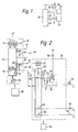
- Figure 2 shows details of the system of Figure 1 incorporating the features of the invention.
- Referring now to Figure 2, the
master unit 10 includes 5 volt and 30volt power supplies power supplies microprocessor 13 and acustom unit 14 connected thereto in themaster unit 10. Each lowcurrent signalling link 40 to aslave unit 20 includes aclock pulse line 41 and asignal line 42. The clock pulse on thelines 41 are of 30 volts amplitude and control the timing of the system time slot assignment multiplex. Within each time slot drive voltage means 15 in thecustom unit 14 connected to eachsignal line 42 apply at any one time a first drive voltage or a second drive voltage to thatsignal line 42. The drive voltage means 15 is a drive voltage circuit shown schematically as a switch. The first drive voltage corresponds to the open switch position shown as applying the fixed voltage of 30 volts via a pull-up resistor R1 and the second drive voltage corresponds to the closed switch position shown as applying zero volts. - In each
slave unit 20, one of which is shown in Figure 2, a 30volt power supply 21 is derived from the clock pulses on theline 41. Ademultiplexing unit 22 hastiming circuits 23 responsive to the clock pulses on theline 41 and from whichswitches 24 are operated to connect the low current signalling link of thesignal line 42 through a corresponding channel in the appropriate assigned time slot. Eachslave unit 20 can connect for example sixteen channels, three of which are shown in Figure 2. - A variable
resistive sensor 50 is shown wired to one of the channels in theslave unit 20. With thesensor 50 connected in thesignal line 42 during the appropriate assigned time slot and thedrive voltage circuit 15 in themaster unit 10 applying the first drive voltage during that time slot, then the voltage on thesignal line 42 is an input signal from thesensor 50 due to its resistance, and this input signal is recognised via an analogue-to-digital converter 16 in themaster unit 10. - An
electrical switch 60 is shown wired to another of the channels in theslave unit 20. With theswitch 60 connected in thesignal line 42 during the appropriate assigned time slot and thedrive voltage circuit 15 in themaster unit 10 applying the first drive voltage during that time slot, then the voltage on thesignal line 42 due to the resistance between two terminals of theswitch 60 is recognised via the analogue-to-digital converter 16 in themaster unit 10 as a binary input signal from theswitch 60. - One other channel in the
slave unit 20 is shown connected in the slave unit to anoutput circuit 25. The state of thedrive voltage circuit 15 during the appropriate assigned time slot will provide an output signal on thesignal line 42 to theoutput circuit 25 to control a high current from the battery +V via afuse 30 to aload 70, for example a lamp, wired to theslave unit 20. - The
microprocessor 13 in themaster unit 10 ensures that the output signal on asignal line 42 to control a high current to aparticular load 70 connected to any one of theslave units 20 is in response to an input signal from aparticular switch 60 which is to be associated with thatload 70 and is connected to any one of theslave units 20. - The low currents in the low current signalling links of the system, for example through the
signal line 42 to theswitch 60 or to theoutput circuit 25 may be, for example, not greater than 5 mA. The high currents through the loads of the system, for example to theload 70 controlled in response to operation of theswitch 60 may be, for example, up to 10 amps. - Referring again to the
output circuit 25, the passage of high current from the battery +V to theload 70 when that load is in normal condition is controlled by the on or off condition of a power switch TR in the form of a power MOSFET transistor having its drain electrode D connected to the battery +V and its source electrode S connected to theload 70. A capacitor CT is connected to the control electrode G of the power switch TR, and thedemultiplexing unit 22 connects the capacitor CT to thesignal line 42 during a time slot, for example 100µs, assigned to the power switch TR in successive frame periods, for example at 100 Hz. Within each time slot assigned to the power switch TR, thedrive voltage circuit 15 applies the first drive voltage or the second drive voltage to charge or discharge the capacitor CT to a high or a low voltage value sufficient respectively to turn the power switch TR on or off. The high voltage value of the capacitor CT is approximately 20 volts determined by the battery +V voltage of approximately 12 volts and by a zener diode Z connected between the capacitor CT and theload 70 to protect the MOSFET power switch TR by limiting its Vgs to approximately 8 volts. The low voltage value of the capacitor CT is zero volts. The leakage in the system is arranged to be sufficiently small that the capacitor CT maintains the power switch TR continously on or continously off between successive frame periods when theload 70 is in normal condition. - In the output circuit 25 a thyristor TH is provided with its two main electrodes connected across the gate electrode G and source electrode S of the power switch TR. The thyristor TH is thus connected to the capacitor CT as well as to the power switch TR, and is moreover connected between the capacitor CT and the
load 70. The thyristor TH is thermally connected to the MOSFET power switch TR and provides protection means for the power switch TR. Thus when theload 70 is in normal condition the thyristor TH is non-conductive. However, if the power switch TR is on with the load in short-circuit condition, the thyristor TH will become conductive above a predetermined temperature responsive to heat generated in the power switch TR so that the power switch TR then turns off. The thyristor may, for example, be designed to turn on at 150°C. In the context of the present system as has been described above, the power switch TR is turned on and maintained continuously on while the capacitor CT is charged at its high voltage value when theload 70 is in normal condition. If the thyristor TH turns on, then the capacitor CT will discharge to its low voltage value, zero volts, via the thyristor TH and theload 70. Then for so long as the thyristor TH is above its turn on temperature, applications of the first drive voltage from thedrive voltage circuit 15 to the capacitor CT will fail to charge the capacitor CT and then the power switch TR will remain turned off. - Possible modifications to the arrangement described in the previous paragraph are as follows. The thyristor TH could be connected across the capacitor CT, so that when the thyristor TH is conductive the capacitor CT discharges through the thyristor TH directly to ground and not via the
load 70. A different semiconductor switch, such as a triac or a bipolar transistor, having a suitable turn on temperature may be used instead of the thyristor. The power switch protection means could, instead of relying on a turn on temperature, be arranged in a suitable circuit so as to become conductive and both turn off the power switch TR and provide a discharge path for the capacitor CT. - The effect of the thyristor TH, or other power switch protection means as described above, on the state of the capacitor CT enables the analogue-to-
digital converter 16 and themicroprocessor 13 in themaster unit 10, with suitable programming of themicroprocessor 13, to provide detection means which are operable to detect the condition of the capacitor CT at a time in a selected time slot assigned to the power switch TR when the capacitor CT will be at the low voltage value of zero volts only if theload 70 is in short-circuit condition and hence to detect whether or not theload 70 is in short-circuit condition. - The
microprocessor 13 in the master unit will be programmed to ensure that the assigned time slot is selected to test theload 70 for short-circuit condition only when the first drive voltage has been applied in that time slot in the preceding frame period. The detection means may conveniently be operated at the beginning of the selected time slot, but if the first drive voltage is applied for the whole of the selected time slot then the detection means can be operated at any time during that selected time slot. - The frequency at which short-circuit testing of a
load 70 is peformed may be selected to meet particular requirements, for example ten times per second, that is at intervals of ten frame periods. When a load becomes short-circuit there will be a small interval before the thyristor TH turns on and enables this condition to be detected. After this there will be small intervals when the thyristor TH temporarily reverts to its non-conductive condition during which the short-circuit condition of the load will not be detected. - When the complete information handling and control system as described above has been manufactured and installed, for example as part of an automotive vehicle electrical system, then all the items connected to the
local slave units 20, that issensors 50, switches 60 and loads 70 may be tested via the central masterintelligent unit 10. In vehicles with driver information displays the test function can be incorporated within themaster unit 10 as a programmable function of themicroprocessor 13. Otherwise, the vehicle builder or vehicle servicer can perform these tests withtest equipment 80 when connected to themaster unit 10. In this case thedrive voltage circuit 15 is operated under control of thetest equipment 80, each time slot selected for load condition testing is selected and the detection means consisting of the analogue-to-digital converter 16 and themicroprocessor 13 are operated under control of thetest equipment 80, and thetest equipment 80 registers whether or not each load is in short-circuit condition. - Before the complete information handling and control system as described above has been manufactured and installed, for example during the manufacturing stages of an automotive vehicle, then each of the items connected to one
local slave unit 20, that is a selection ofsensors 50, switches 60 and loads 70 may be tested usingtest equipment 90 connected to thatslave unit 20. In this case a low current signalling link is provided between thelocal unit 20 and thetest equipment 90, thedrive voltage circuit 15 is reproduced in and operated under control of thetest equipment 90, each time slot selected for load condition testing and the detecting means operated under control of thetest equipment 90, and thetest equipment 90 registers whether or not each load is in short-circuit condition. - The information handling and control system can have application other than to automotive vehicle electrical systems, for example to domestic appliances such as washing machines or to industrial control systems such as for heating and ventilation.
Claims (9)
1. An information handling and control system comprising:
(a) a power switch provided in a local unit to control a high current to a load;
(b) a low current signalling link provided between the local unit and a remote intelligent unit;
(c) a capacitor provided in the local unit connected to the power switch control electrode;
(d) means provided in the local unit for connecting the capacitor to the signalling link during a time slot assigned to the power switch in successive frame periods;
(e) drive voltage means provided in the intelligent unit for applying a first or a second drive voltage within a said assigned time slot respectively to charge or discharge said capacitor to a high or a low voltage value sufficient respectively to turn the power switch on or off, the capacitor maintaining the power switch continuously on or continuously off between successive frame periods when the load is in normal condition;
(f) power switch protection means connected to the power switch and to the capacitor, the protection means being non-conductive when the load is in normal condition and becoming conductive when the power switch is on with the load in short-circuit condition, such that when the protection means is conductive the capacitor discharges to sad low voltage value via the protection means and the power switch turns off;
(g) detection means provided in the intelligent unit which are operable to detect the condition of the capacitor at a time in a selected said assigned time slot when the capacitor will be at said low voltage value only if the load is in a short-circuit condition and hence to detect whether or not the load is in short-circuit condition.
2. A system as claimed in Claim 1, in which the power switch protection means comprises a semiconductor switch thermally conneted to the power switch such that the semiconductor switch becomes conductive above a predetermined temperature responsive to heat generated in the power switch.
3. A system as claimed in Claim 2, in which the semiconductor switch is a thyristor.
4. A system as claimed in any one of Claims 1 to 3, in which the protection means is connected such that the capacitor discharges via the protection means and via the load.
5. An automotive vehicle electrical system including an information handling and control system as claimed in any one of Claims 1 to 4.
6. A system as claimed in any one of Claims 1 to 5, in which the detection means are operable to detect whether or not the load is in short-circuit condition in selected frame periods at intervals of a selected plurality of frame periods.
7. A method of testing said load in a system as claimed in any one of Claims 1 to 6, in which said drive voltage means are operated under control of test equipment connected to the intelligent unit, in which each said selected time slot is selected and said detection means are operated under control of said test equipment, and in which the test equipment registers whether or not the load is in short-circuit condition.
8. A local unit for use in a system as claimed in any one of Claims 1 to 6, said local unit comprising said power switch, said capacitor, said means for connecting the capacitor to the signalling link, and said power switch protection means.
9. A method of testing said load connected to said power switch in a local unit as claimed in Claim 8 before assembly of the local unit in the system, in which said low current signalling link is provided betwen the local unit and test equipment, in which said drive voltage means are reproduced in and are operated under control of the test equipment, in which said detection means are reproduced in the test equipment and each said selected time slot is selected and said detection means are operated under control of the test equipment, and in which the test equipment registers whether or not the load is in short-circuit condition.
Applications Claiming Priority (2)
| Application Number | Priority Date | Filing Date | Title |
|---|---|---|---|
| GB878722195A GB8722195D0 (en) | 1987-09-21 | 1987-09-21 | Information handling & control systems |
| GB8722195 | 1987-09-21 |
Publications (2)
| Publication Number | Publication Date |
|---|---|
| EP0313196A2 true EP0313196A2 (en) | 1989-04-26 |
| EP0313196A3 EP0313196A3 (en) | 1991-03-06 |
Family
ID=10624142
Family Applications (1)
| Application Number | Title | Priority Date | Filing Date |
|---|---|---|---|
| EP19880307953 Withdrawn EP0313196A3 (en) | 1987-09-21 | 1988-08-26 | Control system |
Country Status (7)
| Country | Link |
|---|---|
| US (1) | US4894744A (en) |
| EP (1) | EP0313196A3 (en) |
| JP (1) | JPH01101473A (en) |
| KR (1) | KR890005602A (en) |
| CN (1) | CN1032253A (en) |
| AU (1) | AU2190788A (en) |
| GB (2) | GB8722195D0 (en) |
Cited By (5)
| Publication number | Priority date | Publication date | Assignee | Title |
|---|---|---|---|---|
| EP0503170A1 (en) * | 1991-03-08 | 1992-09-16 | Siemens Aktiengesellschaft | Bus-oriented multiplex system |
| DE4338462A1 (en) * | 1993-11-11 | 1995-05-18 | Hella Kg Hueck & Co | Monitoring system for electrical loads in motor vehicles |
| CN103760895A (en) * | 2014-01-26 | 2014-04-30 | 北京智行鸿远汽车技术有限公司 | Hardware-in-loop test device and method for vehicle-mounted charger control device of new energy automobile |
| CN103760890A (en) * | 2014-01-16 | 2014-04-30 | 北京智行鸿远汽车技术有限公司 | Hardware-in-loop testing device and method for vehicle-mounted battery charger control device of new-energy automobile |
| CN105891647A (en) * | 2016-06-14 | 2016-08-24 | 国网北京市电力公司 | Hardware-in-loop test system of battery charger |
Families Citing this family (3)
| Publication number | Priority date | Publication date | Assignee | Title |
|---|---|---|---|---|
| US5205785A (en) * | 1992-02-13 | 1993-04-27 | Richardson R H | Control system for the ventilating means in a poultry building or the like |
| US5808371A (en) * | 1995-09-05 | 1998-09-15 | Hitachi, Ltd. | Apparatus for driving electrical loads provided at a vehicle |
| US7622562B2 (en) * | 2002-06-26 | 2009-11-24 | Zimmer Orthobiologics, Inc. | Rapid isolation of osteoinductive protein mixtures from mammalian bone tissue |
Citations (4)
| Publication number | Priority date | Publication date | Assignee | Title |
|---|---|---|---|---|
| US3864578A (en) * | 1973-12-26 | 1975-02-04 | Texas Instruments Inc | Multiplex system for a vehicle |
| US4370561A (en) * | 1980-11-28 | 1983-01-25 | Rca Corporation | Vehicle multiplex system |
| GB2144603A (en) * | 1983-08-03 | 1985-03-06 | Rca Corp | Multiplex bus system |
| EP0194915A1 (en) * | 1985-02-27 | 1986-09-17 | Regie Nationale Des Usines Renault | Controlled electric energy-distributing system in an automotive vehicle |
Family Cites Families (5)
| Publication number | Priority date | Publication date | Assignee | Title |
|---|---|---|---|---|
| JPS5272183A (en) * | 1975-12-12 | 1977-06-16 | Mitsubishi Electric Corp | Semiconductor device with protecting device |
| US4435648A (en) * | 1982-12-22 | 1984-03-06 | Emhart Industries, Inc. | Automotive accessory control system |
| US4574266A (en) * | 1983-06-13 | 1986-03-04 | Motorola, Inc. | Electrical load monitoring system and method |
| US4575673A (en) * | 1984-11-01 | 1986-03-11 | United Technologies Corporation | Solid state electronic switch for motor vehicles |
| US4733100A (en) * | 1987-01-14 | 1988-03-22 | Fox Technology, Inc. | Automatic on/off circuit with time delay |
-
1987
- 1987-09-21 GB GB878722195A patent/GB8722195D0/en active Pending
-
1988
- 1988-08-24 GB GB8820131A patent/GB2210220B/en not_active Expired - Lifetime
- 1988-08-26 EP EP19880307953 patent/EP0313196A3/en not_active Withdrawn
- 1988-09-06 US US07/240,678 patent/US4894744A/en not_active Expired - Fee Related
- 1988-09-06 AU AU21907/88A patent/AU2190788A/en not_active Abandoned
- 1988-09-20 KR KR1019880012157A patent/KR890005602A/en not_active Application Discontinuation
- 1988-09-20 JP JP63236196A patent/JPH01101473A/en active Pending
- 1988-09-21 CN CN88106902A patent/CN1032253A/en active Pending
Patent Citations (4)
| Publication number | Priority date | Publication date | Assignee | Title |
|---|---|---|---|---|
| US3864578A (en) * | 1973-12-26 | 1975-02-04 | Texas Instruments Inc | Multiplex system for a vehicle |
| US4370561A (en) * | 1980-11-28 | 1983-01-25 | Rca Corporation | Vehicle multiplex system |
| GB2144603A (en) * | 1983-08-03 | 1985-03-06 | Rca Corp | Multiplex bus system |
| EP0194915A1 (en) * | 1985-02-27 | 1986-09-17 | Regie Nationale Des Usines Renault | Controlled electric energy-distributing system in an automotive vehicle |
Non-Patent Citations (1)
| Title |
|---|
| IEE PROCEEDINGS SECTION A a I vol. 129, no. 6, part E, November 1982, Old Woking, Surrey, GB; N.C.G.N. PRESTON et al.: "Multiprocessor implementation of the logic function of a multiplexed wiring system for automotives" * |
Cited By (7)
| Publication number | Priority date | Publication date | Assignee | Title |
|---|---|---|---|---|
| EP0503170A1 (en) * | 1991-03-08 | 1992-09-16 | Siemens Aktiengesellschaft | Bus-oriented multiplex system |
| DE4338462A1 (en) * | 1993-11-11 | 1995-05-18 | Hella Kg Hueck & Co | Monitoring system for electrical loads in motor vehicles |
| DE4338462B4 (en) * | 1993-11-11 | 2004-04-22 | Hella Kg Hueck & Co. | Control system for electrical consumers in motor vehicles |
| CN103760890A (en) * | 2014-01-16 | 2014-04-30 | 北京智行鸿远汽车技术有限公司 | Hardware-in-loop testing device and method for vehicle-mounted battery charger control device of new-energy automobile |
| CN103760895A (en) * | 2014-01-26 | 2014-04-30 | 北京智行鸿远汽车技术有限公司 | Hardware-in-loop test device and method for vehicle-mounted charger control device of new energy automobile |
| CN105891647A (en) * | 2016-06-14 | 2016-08-24 | 国网北京市电力公司 | Hardware-in-loop test system of battery charger |
| CN105891647B (en) * | 2016-06-14 | 2018-11-09 | 国网北京市电力公司 | The hardware-in―the-loop test system of charger |
Also Published As
| Publication number | Publication date |
|---|---|
| KR890005602A (en) | 1989-05-16 |
| GB8722195D0 (en) | 1987-10-28 |
| GB8820131D0 (en) | 1988-09-28 |
| AU2190788A (en) | 1989-03-23 |
| US4894744A (en) | 1990-01-16 |
| CN1032253A (en) | 1989-04-05 |
| GB2210220A (en) | 1989-06-01 |
| EP0313196A3 (en) | 1991-03-06 |
| JPH01101473A (en) | 1989-04-19 |
| GB2210220B (en) | 1991-09-18 |
Similar Documents
| Publication | Publication Date | Title |
|---|---|---|
| US4894648A (en) | Information handling and control systems, and methods of testing the condition of electrical loads in such systems | |
| US4839530A (en) | Information handling and control systems | |
| KR970004673B1 (en) | Apparatus and method for driving and controlling electric consumers in particular heat plugs | |
| EP0418665A1 (en) | Device for the detection and discrimination of functional faults in an electrical power supply circuit | |
| KR100198517B1 (en) | Method and apparatus for testing a dual airbag passive restraint system | |
| US4894744A (en) | Information handling and control systems, and methods of testing the condition of electrical loads in such systems | |
| US4421976A (en) | System for monitoring heater elements of electric furnaces | |
| JPH0235322B2 (en) | ||
| EP0276082A2 (en) | Information handling and control systems | |
| US5099198A (en) | Circuit configuration for monitoring the final stages of a plurality of valves | |
| US7590140B2 (en) | Method for addressing the participants of a bus system | |
| US4777378A (en) | Information handling and control systems, manually operable electrical switches for use in such systems, and methods of testing such switches in such systems | |
| AU1752692A (en) | Method and apparatus for testing an airbag restraint system with parallel sensors | |
| US5965961A (en) | Electrical circuit arrangement | |
| US5455502A (en) | High speed, large-current power control circuit | |
| US4034369A (en) | Check circuit for checking vehicle warning system | |
| JP2001524408A (en) | Actuator circuit device and inspection method thereof | |
| US6864599B1 (en) | System and method for testing an ignition device | |
| US3594789A (en) | Counter actuated multiplex monitor circuit | |
| US3665207A (en) | Pulse generator | |
| EP0396355A2 (en) | Information handling and control systems | |
| EP0687066A1 (en) | Overvoltage protection device for an integrated circuit and corresponding method | |
| EP0129398A2 (en) | A remote control and monitoring system | |
| GB2192742A (en) | Information handling and control systems | |
| US20220239091A1 (en) | Method and device for connecting a capacitive load assembly to a dc grid |
Legal Events
| Date | Code | Title | Description |
|---|---|---|---|
| PUAI | Public reference made under article 153(3) epc to a published international application that has entered the european phase |
Free format text: ORIGINAL CODE: 0009012 |
|
| AK | Designated contracting states |
Kind code of ref document: A2 Designated state(s): BE DE ES FR GB IT SE |
|
| PUAL | Search report despatched |
Free format text: ORIGINAL CODE: 0009013 |
|
| AK | Designated contracting states |
Kind code of ref document: A3 Designated state(s): BE DE ES FR GB IT SE |
|
| RAP1 | Party data changed (applicant data changed or rights of an application transferred) |
Owner name: VOLEX GROUP PLC |
|
| STAA | Information on the status of an ep patent application or granted ep patent |
Free format text: STATUS: THE APPLICATION IS DEEMED TO BE WITHDRAWN |
|
| 18D | Application deemed to be withdrawn |
Effective date: 19910907 |