EP0321039A1 - Optical scanning unit and an optical read and/or write apparatus comprising such a unit - Google Patents
Optical scanning unit and an optical read and/or write apparatus comprising such a unit Download PDFInfo
- Publication number
- EP0321039A1 EP0321039A1 EP88202838A EP88202838A EP0321039A1 EP 0321039 A1 EP0321039 A1 EP 0321039A1 EP 88202838 A EP88202838 A EP 88202838A EP 88202838 A EP88202838 A EP 88202838A EP 0321039 A1 EP0321039 A1 EP 0321039A1
- Authority
- EP
- European Patent Office
- Prior art keywords
- radiation
- scanning unit
- scanning
- detection elements
- detection system
- Prior art date
- Legal status (The legal status is an assumption and is not a legal conclusion. Google has not performed a legal analysis and makes no representation as to the accuracy of the status listed.)
- Withdrawn
Links
- 230000003287 optical effect Effects 0.000 title claims abstract description 25
- 238000001514 detection method Methods 0.000 claims abstract description 66
- 230000005855 radiation Effects 0.000 claims abstract description 46
- 238000011896 sensitive detection Methods 0.000 claims abstract description 30
- 230000001419 dependent effect Effects 0.000 claims description 5
- 238000003384 imaging method Methods 0.000 claims description 2
- 230000010355 oscillation Effects 0.000 claims description 2
- 230000008859 change Effects 0.000 description 9
- 238000010276 construction Methods 0.000 description 5
- 239000002131 composite material Substances 0.000 description 4
- 239000000725 suspension Substances 0.000 description 4
- 238000000034 method Methods 0.000 description 3
- 210000001747 pupil Anatomy 0.000 description 3
- 230000008901 benefit Effects 0.000 description 1
- 230000003247 decreasing effect Effects 0.000 description 1
- 238000010586 diagram Methods 0.000 description 1
- 230000007246 mechanism Effects 0.000 description 1
- 230000004048 modification Effects 0.000 description 1
- 238000012986 modification Methods 0.000 description 1
- 230000008569 process Effects 0.000 description 1
- 230000009467 reduction Effects 0.000 description 1
- 239000004065 semiconductor Substances 0.000 description 1
- 230000035945 sensitivity Effects 0.000 description 1
Images

Classifications
-
- G—PHYSICS
- G11—INFORMATION STORAGE
- G11B—INFORMATION STORAGE BASED ON RELATIVE MOVEMENT BETWEEN RECORD CARRIER AND TRANSDUCER
- G11B7/00—Recording or reproducing by optical means, e.g. recording using a thermal beam of optical radiation by modifying optical properties or the physical structure, reproducing using an optical beam at lower power by sensing optical properties; Record carriers therefor
- G11B7/08—Disposition or mounting of heads or light sources relatively to record carriers
- G11B7/09—Disposition or mounting of heads or light sources relatively to record carriers with provision for moving the light beam or focus plane for the purpose of maintaining alignment of the light beam relative to the record carrier during transducing operation, e.g. to compensate for surface irregularities of the latter or for track following
- G11B7/0901—Disposition or mounting of heads or light sources relatively to record carriers with provision for moving the light beam or focus plane for the purpose of maintaining alignment of the light beam relative to the record carrier during transducing operation, e.g. to compensate for surface irregularities of the latter or for track following for track following only
-
- G—PHYSICS
- G11—INFORMATION STORAGE
- G11B—INFORMATION STORAGE BASED ON RELATIVE MOVEMENT BETWEEN RECORD CARRIER AND TRANSDUCER
- G11B7/00—Recording or reproducing by optical means, e.g. recording using a thermal beam of optical radiation by modifying optical properties or the physical structure, reproducing using an optical beam at lower power by sensing optical properties; Record carriers therefor
- G11B7/08—Disposition or mounting of heads or light sources relatively to record carriers
- G11B7/085—Disposition or mounting of heads or light sources relatively to record carriers with provision for moving the light beam into, or out of, its operative position or across tracks, otherwise than during the transducing operation, e.g. for adjustment or preliminary positioning or track change or selection
-
- G—PHYSICS
- G11—INFORMATION STORAGE
- G11B—INFORMATION STORAGE BASED ON RELATIVE MOVEMENT BETWEEN RECORD CARRIER AND TRANSDUCER
- G11B7/00—Recording or reproducing by optical means, e.g. recording using a thermal beam of optical radiation by modifying optical properties or the physical structure, reproducing using an optical beam at lower power by sensing optical properties; Record carriers therefor
- G11B7/12—Heads, e.g. forming of the optical beam spot or modulation of the optical beam
- G11B7/13—Optical detectors therefor
Definitions
- the invention relates to an optical scanning unit for scanning an information track on an optically readable record carrier, during which scanning the orientation of the scanning unit changes with respect to the direction of the instantaneously scanned track portion, said scanning unit comprising a radiation source, a radiation-sensitive detection system and an optical system for focusing a scanning beam supplied by the radiation source to form a scanning spot on the record carrier and for imaging the scanning spot on the radiation-sensitive detection system, said detection system comprising a plurality of radiation-sensitive detection elements situated on either side of a bounding line and each supplying an electric output signal which is dependent on the intensity of the radiation incident on the detection element, the difference between the output signals of the detection elements on either side of the bounding line being representative of the magnitude and the direction of a deviation between the centre of the scanning spot and the centre line of the information track.
- the invention also relates to an apparatus for reading and/or writing information in an optically readable record carrier.
- a scanning unit of this type and a read and/or write apparatus of this type are known from United States Patent No. 4,533,826 (PHN 10361).
- the scanning unit described in this Patent comprises a focusing error detection system combined with a tracking system for reading an optical record carrier.
- the intensity destribution of the scanning spot image formed in the plane of the radiation-sensitive detection system is symmetrical with respect to two detectors, if the centre of the scanning spot in the information plane is situated on the centre line of the scanned track. If the scanning spot moves transversely to the track direction, the intensity distribution on the two detectors changes, producing a difference between their output signals. By subtracting the output signals from each other a difference signal is formed which represents the magnitude and the sign of the tracking error and which can be used to correct the position of the scanning unit and hence the scanning spot with respect to the scanned track.
- the information surface may have an information structure consisting of a single continuous track in the form of, for example, a spiral on a disc-shaped record carrier, or of a plurality of short tracks which can be successively scanned by the scanning unit and are, for example, concentrically provided as a plurality of circular tracks on a disc-shaped record carrier.
- a driving means which is used in practice for the optical scanning unit is a pivotal arm which has the scanning unit secured to its end. The scanning unit follows a circular path crossing the track in the information surface at a constantly different angle.
- the movement of the pivotal arm causes the bounding line between the detection elements with which the tracking error signal is generated to rotate with respect to the track direction or, in other words, the effective track direction will extend, for example, at an increasing or a decreasing angle to the bounding line if the read unit moves across the information surface.
- the effective track direction is the direction of the projection of the instantaneously scanned track portion in the plane of the detection system.
- the result of the increase of the angle between the effective track direction and the bounding line is that the difference between the output signals of the detection elements on either side of the bounding line, which difference is associated with a given tracking error, becomes smaller. Due to the tracking error signal becoming smaller, the radial position of the scanning spot can be corrected less accurately, and moreover the sensitivity to interference such as scratches on the record carrier or other surface inaccuracies will increase.
- the above-mentioned phenomenon may become a problem if for a further reduction in size of optical scanning devices shorter pivotal arms are to be used resulting in an increase of the maximum angle between the effective track direction and the bounding line between the first and second detectors.
- the optical scanning unit is characterized in that it comprises means for at least partly compensating the non-parallelism of the effective track direction and the direction of the bounding line.
- the compensation means enable the bounding line to take up different positions and to follow the rotational movement of the effective track direction in the detection system for the greater part.
- Such a compensation can be realized by means of a mechanical construction, for example, in that the said means are constituted by mechanical securing means for the scanning unit, which means realize a compensating movement of the read unit in such a way that during scanning the bounding line remains directed mainly parallel to the effective track direction.
- the direction of the bounding line can then be adapted to the direction of the image of the track.
- Such a rotation may be made, for example, dependent on the position of the suspension mechanism or the pivotal arm.
- the scanning unit may then be suspended to two arms at one end pivotally engaging two pivots mounted on the scanning unit and at the other end pivotally engaging two stationary pivots.
- the stationary pivots are attached to the frame of the write or read apparatus.
- the optical scanning unit which is characterized in that the said means are present within the scanning unit and are constituted by the radiation-sensitive detection system comprising a plurality of detection elements and by an electronic circuit comprising a first sub-circuit for combining the output signals of the detection elements in several different ways to a plurality of tracking error signals each corresponding to a different orientation of the bounding line, and a second sub-circuit for selecting the strongest tracking error signal. Since the different detection elements can be combined by means of an electronic circuit, it is possible to change the orientation of the bounding line with respect to the effective track direction. Such a solution is less costly than a mechanical construction.
- the optical scanning unit according to the invention is further characterized in that the detection elements are combined in the radiation-sensitive detection system in such a way that bounding lines between detection elements extend radially from a central point.
- the detection elements are arranged around a central point.
- the detection elements may have different widths.
- further bounding lines may be provided between detection elements, for example, several detection elements may be juxtaposed in the radial direction.
- This embodiment of the optical scanning unit according to the invention is further characterized in that the detection elements of the radiation-sensitive detection system are combined in four quadrants and in that two of the quadrants each comprise at least two detection elements, said two quadrants being diametrically arranged relative to each other.
- a radiation-sensitive detection system composed of four quadrants is used, for example, in a read unit in which a focusing error signal of the scanning beam with respect to the information plane is determined in accordance with the so-called astigmatic method. This method is described, for example, in United States Patent no. 4,023,033 and can simply be combined with a tracking system according to the invention.
- a further characteristic of the optical scanning unit according to the invention is that the scanning spot can be oscillated in a direction approximately perpendicular to the average direction of the track with an amplitude which is smaller than the dimension of the scanning spot in the information plane, said oscillation modulating the electric signals at the output of the radiation-sensitive detection system, and in that a control circuit is provided to choose the bounding line with the aid of the modulation intensity of the electric signals. Since the amplitude of the thus produced modulation of the electric output signal of a radiation-sensitive detection element increases as the mean radiation intensity on the element increases, it is possible to choose the optimum orientation of the bounding line in this manner.
- the optical scanning unit according to the invention is further characterized in that the control circuit has a threshold to avoid repeated switching between different orientations of the bounding line.
- the threshold may be, for example, a minimum difference in the signal level which should exist between the modulations in detection elements on either side of the bounding line, or a minimum period during which the signal level in the one detection element is larger than in the other.
- Fig. 1 shows coherently an optical record carrier, a scanning unit and means to move the scanning unit and the record carrier with respect to each other.
- the scanning unit shown comprises a semi-conductor laser 1 generating a radiation beam which is focused via an objective system 3 to form a scanning spot in the information surface of the record carrier 5. For the sake of clarity only a single track portion 7 of the tracks in the information surface is shown.
- the radiation reflected by the information surface is projected on a radiation-sensitive detection system 4 by an optical system comprising the objective system 3 and the splitting cube 2.
- the components 1, 2, 3, and 4 of the scanning unit are arranged in a housing 10 secured to a pivotal arm 11.
- the pivotal arm 11 can be moved to and fro by means of the electro-magnetic means 12 and 13 along a circular path as indicated by the arrow 14.
- the record carrier 5 is rotated by means of a motor 15 in the direction indicated by the arrow 16 and as a result of the scanning spot passing the information track 7 the radiation reflected from the information surface is modulated in accordance with the information stored in the track.
- Fig. 2 is a plan view of the path followed by the scanning unit with respect to the record carrier.
- the disc-shaped record carrier 5 on which a plurality of track portions 7 are shown is scanned by the scanning unit whose housing 10 only is shown.
- the scanning unit is suspended to a pivotal arm 11 so that the scanning unit traverses a path 20 during scanning, which path constitutes a portion of a circle.
- the path 20 crosses the tracks on the record carrier at an angle ⁇ which is different in the case of different positions of the pivotal arm with the scanning unit.
- the track portions 7 form part of, for example, a continuous spiral track or of a large number of concentrical circular sub-tracks. In both cases the angle ⁇ at which the path of the scanning unit extends to the direction of the track 7 considerably varies during the movement of the scanning unit along the path 20.
- the tracking servosystem comprises a composite radiation-sensitive detection system having detection elements grouped on either side of a bounding line.
- the difference between output signals of the detection elements on either side of the bounding line is determined by the magnitude and the direction of a deviation between the centre of the scanning spot and the centre line of the scanned track portion and the angle between the bounding line and the effective track direction.
- This difference signal is used to correct the position of the scanning spot with respect to the said centre line, for example, by moving the read unit transversely to the centre line.
- the sum signal of the detection elements is modulated in accordance with the information which has been read and consequently constitutes the information signal.
- the tracking error signal associated with a given tracking error is maximum if the projection of the scanned track portion on the detection plane, indicated by effective track direction in this case, coincides with the bounding line in the radiation-sensitive detection system.
- the angle between the effective track direction and the bounding line changes continuously when moving the read unit from the inner edge of the record carrier to the outer edge, or conversely.
- a construction may be chosen to be such that the effective track direction is parallel to the bounding line if the scanning spot, viewed in the radial direction, is situated approximately in the centre of the track structure. If the scanning spot moves towards the inner edge or towards the outer edge, the angle between the effective track direction and the bounding line increases. When using a short pivotal arm, this angle on the inner or outer edge of the record carrier may become substantially 90°.
- the tracking error signal becomes smaller irrespective of the fact whether the scanning spot is correctly positioned with respect to a scanned track portion. Consequently the accuracy with which the tracking servosystem can correct will be smaller.
- This system is then also more sensitive to interference such as is caused, for example, by scratches on the record carrier.
- Figures 3a and 3b show two embodiments of a suspension of the read unit with which the desired movements of this unit can at least partly be realized.
- the read unit 30 is rigidly connected to two arms 34 and 35.
- the one arm 35 is pivotally connected to the pivotal arm 31 via a pivot 37, which pivotal arm is pivotable about the stationary pivot 33 in the read or write apparatus.
- the other arm 34 is also connected pivotally via a pivot 36 to an auxiliary arm 38 the other end of which is connected pivotally to the stationary pivot 39 in the read or write apparatus.
- the auxiliary arm 38 has a length which is equal to that of the pivotal arm 31 and the stationary pivot 39 is mounted at a distance from the pivot 33 which is equal to the distance between the pivots 36 and 37 at the scanning unit.
- Each of the four pivots 33, 36, 37 and 39 is situated at a vertex of a parallelogram so that the scanning unit assumes the same orientation with respect to the line connecting the two stationary pivots 33 and 39 when rotating the pivotal arm 31.
- the change of the angle between the bounding line and the effective track direction is thus considerably reduced and is identical in the positions at the inner and outer edges of the record carrier.
- the suspension of the read unit as shown in Fig. 3b has two arms or wires 31 and 38 which are pivotally connected at one end to the stationary pivots 33 and 39. At the other end the arms or wires are pivotally connected via the pivots 36 and 37 to the projections 34 and 35 between which the scanning unit 30 is secured.
- a second possibility of adapting the bounding line to the movement of the effective track direction is to use the radiation-sensitive detection system with the associated signal processing circuit for the purpose of determining the effective track direction. If the effective track direction is found to have a given position, the output signals of the detection elements are combined in the signal processing circuit in such a manner that effectively two detectors are obtained whose bounding line fits the effective track direction as satisfactorily as possible.
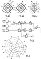
- Figures 4a, 4b and 4c show a first embodiment of a composite detection system 40 in which the bounding line can be rotated.
- This detection system comprises six detectors arranged in four quadrants.
- the detectors 41 and 44 constitute the first and the third quadrant, respectively, the detectors 42 and 43 jointly constitute the second quadrant and the detectors 45 and 46 jointly constitute the fourth quadrant.
- the beam incident on a track of the information surface is diffracted by this track in the radial direction, that is to say a non-diffracted zero-order sub-beam, two sub-beams diffracted in the +1 and -1 order, respectively, and a plurality of second and higher order sub-beams are produced.
- the second and higher order sub-beams largely fall outside the pupil of the objective pupil and may be left out of consideration.
- the image of the objective system is denoted by the circle p in Fig. 4a. If the scanning beam completely fills the pupil, the circle also represents the cross-section of the zero-order sub-beam at the area of the detection system.
- the shaded area g1 is the area of overlap between the -1 order sub-beam b(-1) and the zero-order sub-beam, whilst in the area g2 the +1 order sub-beam b(+1) and the zero-order sub-beam overlap each other.
- the first-order sub-beams have a phase difference with respect to the zero-order sub-beam which does not only depend on the geometry of the track but also on the position of the scanning spot with respect to the centre line of the track. If the centre of the scanning spot is located on the centre line of the track, the phase differences of the first-order sub-beams with respect to the zero-order sub-beam are equal. If the scanning spot is moved transversely to the track direction, the said phase differences change, namely in the opposite sense. Consequently the intensities in the areas g1 and g2 also change in the opposite sense, that is to say, one of the areas will become brighter and the other will become darker, or conversely, dependent on the sign of the movement.
- the movement of the scanning spot with respect to the centre line of the track can be detected, or in other words, a tracking error signal can be obtained.
- the areas g1 and g2 in the detection system are situated symmetrically relative to the projection of the centre line of the track or the effective track direction t c . It will be evident that these two detectors with which the intensities in the overlap areas are determined must be situated on either side of the line t c . For the detection system with six detection elements shown in Figures 4a, 4b and 4c this means that the output signals of the detection elements must be combined in such a way that effectively two detectors are formed whose bounding line S L coincides as satisfactorily as possible with the effective track direction t c .
- Fig. 4b shows the situation in which the scanning spot is situated on the other edge of the record carrier.
- the overlap areas g1 and g2 and the effective track direction are then rotated, for example, through an angle of approximately 45° with respect to the positions in Fig. 4a.
- the overlap areas g1 and g2 and the effective track direction assume a central position corresponding to, for example, a position of the scanning spot on the record carrier halfway the inner edge and the outer edge. Then the signals S r1 and S r2 are approximately equally large and may both be used as a tracking error signal. In the case of a movement from this position it must be decided which of the signals S r1 and S r2 will be used for correction.
- the scanning spot and the scanned track can be periodically moved in the radial direction with respect to each other with an amplitude which is considerably smaller than the dimension of the scanning spot and at a frequency which is several orders of magnitude smaller than the frequency of the information signal which has been read. Due to this induced periodical tracking error the tracking error signals S r1 and S r2 are also modulated at a low frequency component or wobble. By comparing the amplitudes of the low frequency components it can be detected which combination of detection elements yields the largest tracking error signal at a given moment and must thus be selected.
- FIG. 5 An embodiment of an electronic circuit for forming and selecting the tracking error signals S r1 and S r2 is shown in Fig. 5.
- the signals S41 and S42 are applied to a first summation device 50 and the signals S44 and S45 are applied to a second summation device 51.
- the sum signals are subtracted from one another in a first subtractor circuit 52. Its output is connected to a first input of a third summation device 54.
- the second input thereof is connected to an output of a second subtractor circuit 53 whose inputs convey the signals S46 and S43.
- the first tracking error signal S r1 appears at the output of the summation device 54.
- the second tracking error signal S r2 is obtained by means of a third subtractor circuit 55 the two inputs of which are connected to outputs of the components 52 and 53, respectively.
- the tracking error signals S r1 and S r2 are applied to the separate poles of a switch 56 which passes only one of these signals at any instant.
- each signal is successively controlled by bandpass filters 57 and 58, respectively, which pass only one signal at a frequency which is equal to the wobbling frequency and by rectifiers 59 and 60, respectively.
- DC signals which are proportional to the amplitudes of the wobble components of the signals S r1 and S r2 appear at the outputs of these rectifiers.
- These first and second DC components are compared in the comparator 61 which supplies, for example, a positive voltage pulse if the first DC component is larger than the second DC component and which supplies a negative pulse in the reverse case.
- the switch 56 is controlled by means of these pulses.
- the tracks in the record carrier may have a wobbling variation.
- the scanning spot is wobbled.
- the entire scanning unit may be given a wobbling movement in the radial direction or an element in the scanning unit may have a small oscillating movement.
- the division of the radiation-sensitive detection system into four quadrants has the advantage that a focusing error of the scanning beam on the information surface can also be detected by means of this detection system.
- the beam incident on the detection system must then be rendered astigmatic, for example, by arranging a cylindrical lens in the radiation path between the objective system and the radiation-sensitive detection system.
- the round radiation spot on the detection system will change over to an elliptic spot when a focusing error occurs. This change of shape can be determined by means of a four-quadrant detector.
- this radiation-sensitive detection system comprises more than six radiation-sensitive detection elements.
- the effective track direction can rotate further than is shown in the Figures without detracting from the intensity of the tracking error signal.
- more detection elements also yield a better conformity between the effective track direction and the direction of the bounding line.
- Fig. 6 shows an example of another division of a detection system into detection elements.
- the twelve detection elements shown in the Figure are grouped in two rings around a radiation-insensitive central area 100.
- Each of the two rings comprises six sectors 101 to 106 and 111 to 116, respectively.
- This division three choices of the position of the bounding line between two halves of the radiation-sensitive detection system are possible.
- a focusing error signal can also be generated with the detection system shown in Fig. 6, but in a different way than described with reference to Figures 4a, 4b and 4c.
- an annular radiation spot is formed on the detection system (denoted by the broken lines 120 and 121 in Fig. 6) by a cone-shaped element in the path of the beam incident on this system, the centre line of said spot coinciding, in the case of correct focusing, with the circular bounding strip between the composite annular detectors 101 to 106 on the one hand and the composite annular detectors 110 to 116 on the other hand.
- a circular symmetrical change of the radiation distribution over the annular detectors occurs. This change can be detected by subtracting the sum signal of the detectors 101 to 106 from the sum signal of the detectors 111 to 116.
- a signal is obtained by means of adding all detector signals, which signal represents the information read from the record carrier.
- the invention has been described with reference to an invention for reading a record carrier on which prerecorded information is provided, but it may alternatively be used in an apparatus for writing information in a record carrier having empty or blank tracks.
- the write apparatus principally has the same structure as the read apparatus but is also provided with known means for intensity-modulating the write beam in conformity with the information to be written.
Abstract
A scanning unit for an optical read and/or write apparatus comprises a radiation-sensitive detection system (40) composed of a plurality of radiation-sensitive detection elements (41-46). The tracking error signal is determined by combining the detection elements on either side of a bounding line (SL) to two detector halves (41, 42, 46 and 43, 44, 45) and by comparing the received radiation intensity in the two halves. By combining the detection elements in different ways, the orientation of the bounding line is modified and adapted to the direction of the image (tc) on the detection system (40) of the centre line of the track to be read or written.
Description
- The invention relates to an optical scanning unit for scanning an information track on an optically readable record carrier, during which scanning the orientation of the scanning unit changes with respect to the direction of the instantaneously scanned track portion, said scanning unit comprising a radiation source, a radiation-sensitive detection system and an optical system for focusing a scanning beam supplied by the radiation source to form a scanning spot on the record carrier and for imaging the scanning spot on the radiation-sensitive detection system, said detection system comprising a plurality of radiation-sensitive detection elements situated on either side of a bounding line and each supplying an electric output signal which is dependent on the intensity of the radiation incident on the detection element, the difference between the output signals of the detection elements on either side of the bounding line being representative of the magnitude and the direction of a deviation between the centre of the scanning spot and the centre line of the information track. The invention also relates to an apparatus for reading and/or writing information in an optically readable record carrier.
- A scanning unit of this type and a read and/or write apparatus of this type are known from United States Patent No. 4,533,826 (PHN 10361). The scanning unit described in this Patent comprises a focusing error detection system combined with a tracking system for reading an optical record carrier.
- In the known unit it is ensured that the intensity destribution of the scanning spot image formed in the plane of the radiation-sensitive detection system is symmetrical with respect to two detectors, if the centre of the scanning spot in the information plane is situated on the centre line of the scanned track. If the scanning spot moves transversely to the track direction, the intensity distribution on the two detectors changes, producing a difference between their output signals. By subtracting the output signals from each other a difference signal is formed which represents the magnitude and the sign of the tracking error and which can be used to correct the position of the scanning unit and hence the scanning spot with respect to the scanned track.
- The information surface may have an information structure consisting of a single continuous track in the form of, for example, a spiral on a disc-shaped record carrier, or of a plurality of short tracks which can be successively scanned by the scanning unit and are, for example, concentrically provided as a plurality of circular tracks on a disc-shaped record carrier.
- To enable the scanning spot to scan the entire spiral track or all concentrical tracks, it should be possible to move the spot transversely to the track direction,i.e. in the radial direction in the case of a disc-shaped record carrier. If the optical scanning unit has a sufficiently light construction, that is to say, the assembly of elements constituting a scanning spot on the information surface and converting the radiation emitted from the information surface into electric signals, this movement of the scanning spot can be realized by moving the entire optical scanning unit in the radial direction. A driving means which is used in practice for the optical scanning unit is a pivotal arm which has the scanning unit secured to its end. The scanning unit follows a circular path crossing the track in the information surface at a constantly different angle. The movement of the pivotal arm causes the bounding line between the detection elements with which the tracking error signal is generated to rotate with respect to the track direction or, in other words, the effective track direction will extend, for example, at an increasing or a decreasing angle to the bounding line if the read unit moves across the information surface. The effective track direction is the direction of the projection of the instantaneously scanned track portion in the plane of the detection system. The result of the increase of the angle between the effective track direction and the bounding line is that the difference between the output signals of the detection elements on either side of the bounding line, which difference is associated with a given tracking error, becomes smaller. Due to the tracking error signal becoming smaller, the radial position of the scanning spot can be corrected less accurately, and moreover the sensitivity to interference such as scratches on the record carrier or other surface inaccuracies will increase.
- The above-mentioned phenomenon may become a problem if for a further reduction in size of optical scanning devices shorter pivotal arms are to be used resulting in an increase of the maximum angle between the effective track direction and the bounding line between the first and second detectors.
- It is an object of the invention to provide a scanning unit enabling a sufficiently large and sufficiently accurate tracking error signal to be generated also when the angle between the path of the read unit and the optically readable track changes considerably.
- To this end the optical scanning unit according to the invention is characterized in that it comprises means for at least partly compensating the non-parallelism of the effective track direction and the direction of the bounding line. The compensation means enable the bounding line to take up different positions and to follow the rotational movement of the effective track direction in the detection system for the greater part.
- Such a compensation can be realized by means of a mechanical construction, for example, in that the said means are constituted by mechanical securing means for the scanning unit, which means realize a compensating movement of the read unit in such a way that during scanning the bounding line remains directed mainly parallel to the effective track direction. By rotation of at least a part of the scanning unit, the direction of the bounding line can then be adapted to the direction of the image of the track. Such a rotation may be made, for example, dependent on the position of the suspension mechanism or the pivotal arm. The scanning unit may then be suspended to two arms at one end pivotally engaging two pivots mounted on the scanning unit and at the other end pivotally engaging two stationary pivots. The stationary pivots are attached to the frame of the write or read apparatus. By suitable choice of the length of the arms and the mutual distance between the pivots the rotation of the scanning unit with respect to the direction of the information track can be compensated.
- An elaboration of the inventive concept is embodied in the optical scanning unit according to the invention which is characterized in that the said means are present within the scanning unit and are constituted by the radiation-sensitive detection system comprising a plurality of detection elements and by an electronic circuit comprising a first sub-circuit for combining the output signals of the detection elements in several different ways to a plurality of tracking error signals each corresponding to a different orientation of the bounding line, and a second sub-circuit for selecting the strongest tracking error signal. Since the different detection elements can be combined by means of an electronic circuit, it is possible to change the orientation of the bounding line with respect to the effective track direction. Such a solution is less costly than a mechanical construction.
- The optical scanning unit according to the invention is further characterized in that the detection elements are combined in the radiation-sensitive detection system in such a way that bounding lines between detection elements extend radially from a central point. In this embodiment the detection elements are arranged around a central point. The detection elements may have different widths. Dependent on different functions which must be fulfilled by the detection system simultaneously with the tracking process, further bounding lines may be provided between detection elements, for example, several detection elements may be juxtaposed in the radial direction.
- This embodiment of the optical scanning unit according to the invention is further characterized in that the detection elements of the radiation-sensitive detection system are combined in four quadrants and in that two of the quadrants each comprise at least two detection elements, said two quadrants being diametrically arranged relative to each other. Such a radiation-sensitive detection system composed of four quadrants is used, for example, in a read unit in which a focusing error signal of the scanning beam with respect to the information plane is determined in accordance with the so-called astigmatic method. This method is described, for example, in United States Patent no. 4,023,033 and can simply be combined with a tracking system according to the invention.
- A further characteristic of the optical scanning unit according to the invention is that the scanning spot can be oscillated in a direction approximately perpendicular to the average direction of the track with an amplitude which is smaller than the dimension of the scanning spot in the information plane, said oscillation modulating the electric signals at the output of the radiation-sensitive detection system, and in that a control circuit is provided to choose the bounding line with the aid of the modulation intensity of the electric signals. Since the amplitude of the thus produced modulation of the electric output signal of a radiation-sensitive detection element increases as the mean radiation intensity on the element increases, it is possible to choose the optimum orientation of the bounding line in this manner.
- The optical scanning unit according to the invention is further characterized in that the control circuit has a threshold to avoid repeated switching between different orientations of the bounding line. The threshold may be, for example, a minimum difference in the signal level which should exist between the modulations in detection elements on either side of the bounding line, or a minimum period during which the signal level in the one detection element is larger than in the other.
- The invention will now be described in greater detail by way of example with reference to the accompanying drawings in which
- Fig. 1 shows a suspension of a scanning unit to a pivotal arm in a disc-shaped record carrier,
- Fig. 2 is a plan view of the path followed by the scanning unit with respect to the record carrier,
- Figures 3a and 3b show mechanical constructions to influence the orientation of the write or read unit,
- Figures 4a, 4b and 4c show a detection system according to the invention, comprising radiation-sensitive detection elements with an image of a radiation spot,
- Fig. 5 is a block diagram of a circuit for forming and selecting tracking error signals, and
- Fig. 6 shows an alternative radiation-sensitive detection system.
- Fig. 1 shows coherently an optical record carrier, a scanning unit and means to move the scanning unit and the record carrier with respect to each other. The scanning unit shown comprises a
semi-conductor laser 1 generating a radiation beam which is focused via anobjective system 3 to form a scanning spot in the information surface of the record carrier 5. For the sake of clarity only a single track portion 7 of the tracks in the information surface is shown. The radiation reflected by the information surface is projected on a radiation-sensitive detection system 4 by an optical system comprising theobjective system 3 and the splittingcube 2. Thecomponents housing 10 secured to apivotal arm 11. Thepivotal arm 11 can be moved to and fro by means of the electro-magnetic means arrow 14. The record carrier 5 is rotated by means of amotor 15 in the direction indicated by thearrow 16 and as a result of the scanning spot passing the information track 7 the radiation reflected from the information surface is modulated in accordance with the information stored in the track. - Fig. 2 is a plan view of the path followed by the scanning unit with respect to the record carrier. The disc-shaped record carrier 5 on which a plurality of track portions 7 are shown is scanned by the scanning unit whose
housing 10 only is shown. The scanning unit is suspended to apivotal arm 11 so that the scanning unit traverses apath 20 during scanning, which path constitutes a portion of a circle. Thepath 20 crosses the tracks on the record carrier at an angle α which is different in the case of different positions of the pivotal arm with the scanning unit. - The track portions 7 form part of, for example, a continuous spiral track or of a large number of concentrical circular sub-tracks. In both cases the angle α at which the path of the scanning unit extends to the direction of the track 7 considerably varies during the movement of the scanning unit along the
path 20. - To cause the scanning unit to follow the track during scanning of the record carrier, a tracking system is integrated with the scanning unit. The tracking servosystem comprises a composite radiation-sensitive detection system having detection elements grouped on either side of a bounding line. When moving the scanning spot at right angles to the track direction, the radiation intensity in the image in the detection plane of this scanning spot shifts transversely to the effective track direction, i.e. the direction of the image in the detection plane of the information track. The difference between output signals of the detection elements on either side of the bounding line is determined by the magnitude and the direction of a deviation between the centre of the scanning spot and the centre line of the scanned track portion and the angle between the bounding line and the effective track direction. This difference signal is used to correct the position of the scanning spot with respect to the said centre line, for example, by moving the read unit transversely to the centre line. The sum signal of the detection elements is modulated in accordance with the information which has been read and consequently constitutes the information signal.
- The tracking error signal associated with a given tracking error is maximum if the projection of the scanned track portion on the detection plane, indicated by effective track direction in this case, coincides with the bounding line in the radiation-sensitive detection system.
- If, as is shown in Figures 1 and 2, the read unit is secured to a pivotal arm, the angle between the effective track direction and the bounding line changes continuously when moving the read unit from the inner edge of the record carrier to the outer edge, or conversely. A construction may be chosen to be such that the effective track direction is parallel to the bounding line if the scanning spot, viewed in the radial direction, is situated approximately in the centre of the track structure. If the scanning spot moves towards the inner edge or towards the outer edge, the angle between the effective track direction and the bounding line increases. When using a short pivotal arm, this angle on the inner or outer edge of the record carrier may become substantially 90°.
- When radially moving the scanning spot from the central position to the extreme positions, the tracking error signal becomes smaller irrespective of the fact whether the scanning spot is correctly positioned with respect to a scanned track portion. Consequently the accuracy with which the tracking servosystem can correct will be smaller. This system is then also more sensitive to interference such as is caused, for example, by scratches on the record carrier.
- According to the invention it is ensured that the rotation of the effective track direction is followed by the bounding line to a greater or lesser extent. When moving the scanning spot in the radial direction with respect to the record carrier, this can be mechanically realized by causing the scanning unit to rotate about its axis so that also the bounding line is rotated.
- Figures 3a and 3b show two embodiments of a suspension of the read unit with which the desired movements of this unit can at least partly be realized.
- In Fig. 3a the
read unit 30 is rigidly connected to twoarms arm 35 is pivotally connected to thepivotal arm 31 via apivot 37, which pivotal arm is pivotable about thestationary pivot 33 in the read or write apparatus. Theother arm 34 is also connected pivotally via apivot 36 to anauxiliary arm 38 the other end of which is connected pivotally to thestationary pivot 39 in the read or write apparatus. Theauxiliary arm 38 has a length which is equal to that of thepivotal arm 31 and thestationary pivot 39 is mounted at a distance from thepivot 33 which is equal to the distance between thepivots pivots stationary pivots pivotal arm 31. The change of the angle between the bounding line and the effective track direction is thus considerably reduced and is identical in the positions at the inner and outer edges of the record carrier. - The suspension of the read unit as shown in Fig. 3b has two arms or
wires stationary pivots pivots projections scanning unit 30 is secured. - When moving the
scanning unit 30, for example, by means of magnetic means that act on a part of the housing, it simultaneously undergoes a rotation with respect to the line between thepivots wires pivots - A second possibility of adapting the bounding line to the movement of the effective track direction is to use the radiation-sensitive detection system with the associated signal processing circuit for the purpose of determining the effective track direction. If the effective track direction is found to have a given position, the output signals of the detection elements are combined in the signal processing circuit in such a manner that effectively two detectors are obtained whose bounding line fits the effective track direction as satisfactorily as possible.
- Figures 4a, 4b and 4c show a first embodiment of a
composite detection system 40 in which the bounding line can be rotated. This detection system comprises six detectors arranged in four quadrants. Thedetectors detectors detectors - As is known, the beam incident on a track of the information surface is diffracted by this track in the radial direction, that is to say a non-diffracted zero-order sub-beam, two sub-beams diffracted in the +1 and -1 order, respectively, and a plurality of second and higher order sub-beams are produced. The second and higher order sub-beams largely fall outside the pupil of the objective pupil and may be left out of consideration. The image of the objective system is denoted by the circle p in Fig. 4a. If the scanning beam completely fills the pupil, the circle also represents the cross-section of the zero-order sub-beam at the area of the detection system. The shaded area g₁ is the area of overlap between the -1 order sub-beam b(-1) and the zero-order sub-beam, whilst in the area g₂ the +1 order sub-beam b(+1) and the zero-order sub-beam overlap each other.
- The first-order sub-beams have a phase difference with respect to the zero-order sub-beam which does not only depend on the geometry of the track but also on the position of the scanning spot with respect to the centre line of the track. If the centre of the scanning spot is located on the centre line of the track, the phase differences of the first-order sub-beams with respect to the zero-order sub-beam are equal. If the scanning spot is moved transversely to the track direction, the said phase differences change, namely in the opposite sense. Consequently the intensities in the areas g₁ and g₂ also change in the opposite sense, that is to say, one of the areas will become brighter and the other will become darker, or conversely, dependent on the sign of the movement. By placing two detectors at the positions of the areas g₁ and g₂ and by determining the difference between the output signals of the detectors, the movement of the scanning spot with respect to the centre line of the track can be detected, or in other words, a tracking error signal can be obtained.
- Since the first-order sub-beams b(+1) and b(-1) are diffracted through equally large but opposite angles, the areas g₁ and g₂ in the detection system are situated symmetrically relative to the projection of the centre line of the track or the effective track direction tc. It will be evident that these two detectors with which the intensities in the overlap areas are determined must be situated on either side of the line tc. For the detection system with six detection elements shown in Figures 4a, 4b and 4c this means that the output signals of the detection elements must be combined in such a way that effectively two detectors are formed whose bounding line SL coincides as satisfactorily as possible with the effective track direction tc.
- In the situation shown in Fig. 4a which corresponds, for example, to a position of the pivotal arm such that the scanning spot is situated on the one edge of the record carrier, the signals (S) of the
detection elements detection elements - Fig. 4b shows the situation in which the scanning spot is situated on the other edge of the record carrier. The overlap areas g₁ and g₂ and the effective track direction are then rotated, for example, through an angle of approximately 45° with respect to the positions in Fig. 4a. By summing the signals of the
detection elements detection elements
Sr2= (S₄₁ + S₄₂ + S₄₃) - (S₄₄ + S₄₅ + S₄₆). - In Fig. 4c the overlap areas g₁ and g₂ and the effective track direction assume a central position corresponding to, for example, a position of the scanning spot on the record carrier halfway the inner edge and the outer edge. Then the signals Sr1 and Sr2 are approximately equally large and may both be used as a tracking error signal. In the case of a movement from this position it must be decided which of the signals Sr1 and Sr2 will be used for correction.
- To take this decision, the scanning spot and the scanned track can be periodically moved in the radial direction with respect to each other with an amplitude which is considerably smaller than the dimension of the scanning spot and at a frequency which is several orders of magnitude smaller than the frequency of the information signal which has been read. Due to this induced periodical tracking error the tracking error signals Sr1 and Sr2 are also modulated at a low frequency component or wobble. By comparing the amplitudes of the low frequency components it can be detected which combination of detection elements yields the largest tracking error signal at a given moment and must thus be selected.
- An embodiment of an electronic circuit for forming and selecting the tracking error signals Sr1 and Sr2 is shown in Fig. 5. The signals S₄₁ and S₄₂ are applied to a
first summation device 50 and the signals S₄₄ and S₄₅ are applied to asecond summation device 51. The sum signals are subtracted from one another in afirst subtractor circuit 52. Its output is connected to a first input of athird summation device 54. The second input thereof is connected to an output of asecond subtractor circuit 53 whose inputs convey the signals S₄₆ and S₄₃. The first tracking error signal Sr1 appears at the output of thesummation device 54. The second tracking error signal Sr2 is obtained by means of a third subtractor circuit 55 the two inputs of which are connected to outputs of thecomponents - The tracking error signals Sr1 and Sr2 are applied to the separate poles of a
switch 56 which passes only one of these signals at any instant. For selecting one of the two signals each signal is successively controlled bybandpass filters rectifiers comparator 61 which supplies, for example, a positive voltage pulse if the first DC component is larger than the second DC component and which supplies a negative pulse in the reverse case. Theswitch 56 is controlled by means of these pulses. - For generating a wobble component in a tracking error signal the tracks in the record carrier may have a wobbling variation. Preferably, however, the scanning spot is wobbled. To this end the entire scanning unit may be given a wobbling movement in the radial direction or an element in the scanning unit may have a small oscillating movement.
- The division of the radiation-sensitive detection system into four quadrants has the advantage that a focusing error of the scanning beam on the information surface can also be detected by means of this detection system. The beam incident on the detection system must then be rendered astigmatic, for example, by arranging a cylindrical lens in the radiation path between the objective system and the radiation-sensitive detection system. As described in United States Patent 4,023,033 the round radiation spot on the detection system will change over to an elliptic spot when a focusing error occurs. This change of shape can be determined by means of a four-quadrant detector. The focusing error signal Sf of the detector configuration of Figures 4a, 4b and 4c is given by:
Sf= (S₄₁ + S₄₄) - (S₄₂ + S₄₃ + S₄₅ + S₄₆). - In a modification of the detection system according to Figures 4a, 4b and 4c this radiation-sensitive detection system comprises more than six radiation-sensitive detection elements. When using more detection elements in the detection system, for example, the effective track direction can rotate further than is shown in the Figures without detracting from the intensity of the tracking error signal. On the other hand more detection elements also yield a better conformity between the effective track direction and the direction of the bounding line.
- Fig. 6 shows an example of another division of a detection system into detection elements. The twelve detection elements shown in the Figure are grouped in two rings around a radiation-insensitive
central area 100. Each of the two rings comprises sixsectors 101 to 106 and 111 to 116, respectively. With this division three choices of the position of the bounding line between two halves of the radiation-sensitive detection system are possible. - A focusing error signal can also be generated with the detection system shown in Fig. 6, but in a different way than described with reference to Figures 4a, 4b and 4c. For example, an annular radiation spot is formed on the detection system (denoted by the
broken lines annular detectors 101 to 106 on the one hand and the composite annular detectors 110 to 116 on the other hand. When defocusing the scanning beam on the information surface a circular symmetrical change of the radiation distribution over the annular detectors occurs. This change can be detected by subtracting the sum signal of thedetectors 101 to 106 from the sum signal of thedetectors 111 to 116. - It is to be noted that in the said embodiments a signal is obtained by means of adding all detector signals, which signal represents the information read from the record carrier.
- It is true that the invention has been described with reference to an invention for reading a record carrier on which prerecorded information is provided, but it may alternatively be used in an apparatus for writing information in a record carrier having empty or blank tracks. The write apparatus principally has the same structure as the read apparatus but is also provided with known means for intensity-modulating the write beam in conformity with the information to be written.
Claims (6)
1. An optical scanning unit for scanning an information track on an optically readable record carrier, during which scanning the orientation of the scanning unit changes with respect to the direction of the instantaneously scanned track portion, said scanning unit comprising a radiation source, a radiation-sensitive detection system and an optical system for focusing a scanning beam supplied by the radiation source to form a scanning spot on the record carrier and for imaging the scanning spot on the radiation-sensitive detection system, said detection system comprising a plurality of radiation-sensitive detection elements situated on either side of a bounding line and each supplying an electric output signal which is dependent on the intensity of the radiation incident on the detection element, the difference between the output signals of the detection elements on either side of the bounding line being representative of the magnitude and the direction of a deviation between the centre of the scanning spot and the centre line of the information track, characterized in that the scanning unit comprises means for at least partly compensating the non-parallelism of the effective track direction and the direction of the bounding line, said means being present within the scanning unit and being constituted by the radiation-sensitive detection system comprising a plurality of detection elements and by an electronic circuit comprising a first sub-circuit for combining the output signals of the detection elements in several different ways to a plurality of tracking error signals each corresponding to a different orientation of the bounding line, and a second sub-circuit for selecting the strongest tracking error signal.
2. An optical scanning unit as claimed in Claim 1, characterized in that the detection elements are combined in the radiation-sensitive detection system in such a way that bounding lines between detection elements extend radially from a central point.
3. An optical scanning unit as claimed in Claim 2, characterized in that the detection elements of the radiation-sensitive detection system are combined in four quadrants and in that two of the quadrants each comprise at least two detection elements, said two quadrants being diametrically arranged relative to each other.
4. An optical scanning unit as claimed in Claim 1, 2 or 3, characterized in that the scanning spot can be oscillated in a direction approximately perpendicular to the average direction of the image of the track with an amplitude which is smaller than the dimension of the scanning spot on the record carrier, said oscillation modulating the electric signals at the output of the radiation-sensitive detection system, and in that a control circuit is provided to choose the bounding line with the aid of the modulation intensity of the electric signals.
5. An optical scanning unit as claimed in Claim 4, characterized in that the control circuit has a threshold to avoid repeated switching between different orientations of the bounding line.
6. An apparatus for reading and/or writing information in an optically readable record carrier comprising tracks, said apparatus comprising an optical scanning unit as claimed in any one of the preceding Claims.
Applications Claiming Priority (2)
| Application Number | Priority Date | Filing Date | Title |
|---|---|---|---|
| NL8703041 | 1987-12-16 | ||
| NL8703041A NL8703041A (en) | 1987-12-16 | 1987-12-16 | OPTICAL PROBE AND AN OPTICAL READING AND / OR REGISTRATION DEVICE THEREOF. |
Publications (1)
| Publication Number | Publication Date |
|---|---|
| EP0321039A1 true EP0321039A1 (en) | 1989-06-21 |
Family
ID=19851104
Family Applications (1)
| Application Number | Title | Priority Date | Filing Date |
|---|---|---|---|
| EP88202838A Withdrawn EP0321039A1 (en) | 1987-12-16 | 1988-12-12 | Optical scanning unit and an optical read and/or write apparatus comprising such a unit |
Country Status (5)
| Country | Link |
|---|---|
| US (1) | US4864118A (en) |
| EP (1) | EP0321039A1 (en) |
| JP (1) | JPH01196739A (en) |
| KR (1) | KR890010823A (en) |
| NL (1) | NL8703041A (en) |
Cited By (2)
| Publication number | Priority date | Publication date | Assignee | Title |
|---|---|---|---|---|
| GB2307548A (en) * | 1995-11-23 | 1997-05-28 | Thomson Multimedia Sa | Optical disk pickup using a six segment photodetector for tracking control |
| CN110824457A (en) * | 2019-11-05 | 2020-02-21 | 广西大学 | Three-dimensional laser scanning system capable of avoiding shielding |
Families Citing this family (51)
| Publication number | Priority date | Publication date | Assignee | Title |
|---|---|---|---|---|
| NL9002007A (en) * | 1990-09-12 | 1992-04-01 | Philips Nv | DEVICE FOR SCANNING AN INFORMATION SHEET WITH OPTICAL RADIATION. |
| JPH04129048A (en) * | 1990-09-19 | 1992-04-30 | Fujitsu Ltd | Optical head device |
| US5432763A (en) * | 1993-03-15 | 1995-07-11 | Hewlett-Packard Company | Subminiature rotary actuator optical head |
| US6590853B1 (en) * | 1998-03-30 | 2003-07-08 | Samsung Electronics Co., Ltd. | Swing arm driving type optical recording/reproducing apparatus |
| US6580683B1 (en) | 1999-06-23 | 2003-06-17 | Dataplay, Inc. | Optical recording medium having a master data area and a writeable data area |
| US7196979B2 (en) | 2001-01-25 | 2007-03-27 | Dphi Acquisitions, Inc. | Calibration storage methods for a digital focus and tracking servo system with calibration |
| US6813228B2 (en) | 2001-01-25 | 2004-11-02 | Dphi Acquisitions, Inc. | Tracking and focus servo system with direction sensor |
| US7023776B2 (en) * | 2001-01-25 | 2006-04-04 | Dphi Acquisitions, Inc. | Calibration initiation methods for a tracking and focus servo system |
| US6882601B2 (en) | 2001-01-25 | 2005-04-19 | Dphi Acquisitions, Inc. | Digital servo system with feed-forward control loops |
| US6809995B2 (en) | 2001-01-25 | 2004-10-26 | Dphi Acquisitions, Inc. | Digital focus and tracking servo system |
| US6813226B2 (en) | 2001-01-25 | 2004-11-02 | Dphi Acquisitions, Inc. | Calibration of a focus sum threshold in a focus servo system |
| US6762980B2 (en) | 2001-01-25 | 2004-07-13 | Dphi Acquisitions, Inc. | Digital tracking servo system with a multi-track seeking and accelerated servo function for regaining a closed tracking loop |
| US6891781B2 (en) * | 2001-01-25 | 2005-05-10 | Dphi Acquisitions, Inc. | Digital servo system with second order compensator |
| US6922380B2 (en) | 2001-01-25 | 2005-07-26 | Dphi Acquisitions, Inc. | Tracking and focus servo system with anti-skate algorithm |
| US6965547B2 (en) * | 2001-01-25 | 2005-11-15 | Dphi Acquisitions, Inc. | Tracking and focus servo system with error signal inverse non-linearity calibration |
| US7522480B2 (en) | 2001-01-25 | 2009-04-21 | Dphi Acquisitions, Inc. | Digital tracking servo system with multi-track seek with an acceleration clamp |
| US7016280B2 (en) * | 2001-01-25 | 2006-03-21 | Dphi Acquisitions, Inc. | Tracking and focus servo system with defect detection |
| US7782721B2 (en) * | 2001-01-25 | 2010-08-24 | Dphi Acquisitions, Inc. | Digital focus and tracking servo system with multi-zone calibration |
| US7680004B2 (en) * | 2001-01-25 | 2010-03-16 | Dphi Acquisitions, Inc. | Digital servo system with inverse non-linearity compensation |
| US7020054B2 (en) * | 2001-01-25 | 2006-03-28 | Dphi Acquisitions, Inc. | Digital servo system with biased feed-forward |
| US6882603B2 (en) | 2001-01-25 | 2005-04-19 | Dphi Acquisitions, Inc. | Digital tracking servo system with tracking skate detection |
| US6970410B2 (en) * | 2001-01-25 | 2005-11-29 | Dphi Acquisitions, Inc. | Focus detection in a digital focus servo system |
| US6738320B2 (en) | 2001-01-25 | 2004-05-18 | Dphi Acquisitions, Inc. | System and method for moving optical pick up from current position to target position with smooth control |
| US6909676B2 (en) | 2001-01-25 | 2005-06-21 | Dphi Acquisitions, Inc. | Digital tracking servo system with multi-track seek with track zero crossing detection |
| US6847596B2 (en) | 2001-01-25 | 2005-01-25 | Dphi Acquisitions, Inc. | Tracking servo system including a multi-track seek algorithm with a track zero crossing period integrity test |
| US6970403B2 (en) * | 2001-01-25 | 2005-11-29 | Dphi Acquisition, Inc. | Calibration of tracking error signal offset in a tracking servo system |
| US6904007B2 (en) * | 2001-01-25 | 2005-06-07 | Dphi Acquisitions, Inc. | Digital servo system with loop gain calibration |
| US7023766B2 (en) | 2001-01-25 | 2006-04-04 | Dphi Acquisitions, Inc. | Flexible servicing of servo algorithms using a digital signal processor |
| US7593300B2 (en) | 2001-01-25 | 2009-09-22 | Dphi Acquisitions, Inc. | Digital tracking servo system with off-format detection |
| US7092322B2 (en) * | 2001-01-25 | 2006-08-15 | Dphi Acquisitions, Inc. | Calibration of focus error signal offset in a focus servo system |
| US6937543B2 (en) | 2001-01-25 | 2005-08-30 | Dphi Acquisitions, Inc. | Digital focus servo system with a sliding notch filter |
| US6950380B2 (en) * | 2001-01-25 | 2005-09-27 | Dphi Acquisitions, Inc. | Detector input dark current offset calibration in an optical disk drive digital servo |
| US6885619B2 (en) * | 2001-01-25 | 2005-04-26 | Dphi Acquisitions, Inc. | Detector input stray light offset calibration in an optical disk drive |
| US6847597B2 (en) | 2001-01-25 | 2005-01-25 | Dphi Acquisitions, Inc. | Optical disk drive with a digital focus and tracking servo system |
| US6958957B2 (en) * | 2001-01-25 | 2005-10-25 | Dphi Acquisitions, Inc. | Digital tracking and focus servo system with TES to FES crosstalk calibration |
| US6891789B2 (en) * | 2001-01-25 | 2005-05-10 | Dphi Acquisitions, Inc. | Tracking and focus servo system with automatic media type detector |
| US6704261B2 (en) | 2001-01-25 | 2004-03-09 | Dphi Acquisitions, Inc. | Spin motor control in an optical drive |
| US6956797B2 (en) * | 2001-01-25 | 2005-10-18 | Dphi Acquisitions, Inc. | Digital servo system with error signal integrity testing |
| US6728182B2 (en) | 2001-01-25 | 2004-04-27 | Dphi Acquisitions, Inc. | Tracking and focus servo system with a media type boundary crossing detector |
| US6781929B2 (en) | 2001-01-25 | 2004-08-24 | Dphi Acquisitions, Inc. | Digital tracking servo system with multi-track seek |
| US7492675B2 (en) * | 2001-01-25 | 2009-02-17 | Dphi Acquisitions, Inc. | Digital servo system with calibrated notch filters |
| US7095683B2 (en) * | 2001-01-25 | 2006-08-22 | Dphi Acquisitions, Inc. | Tracking and focus digital servo system with write abort |
| US7672199B2 (en) | 2001-01-25 | 2010-03-02 | Dphi Acquisitions, Inc. | Close focus algorithm in a digital focus servo system |
| US7414940B2 (en) | 2001-01-25 | 2008-08-19 | Dphi Acquisitions, Inc. | Calibration of a focus error signal gain in a focus servo system |
| US7260031B2 (en) | 2001-01-25 | 2007-08-21 | Dphi Acquisitions, Inc. | Digital focus and tracking servo system with one-track jump |
| US6930963B2 (en) | 2001-01-25 | 2005-08-16 | Dphi Acquistions, Inc. | Tracking and focus servo system with head load |
| US6906985B2 (en) | 2001-01-25 | 2005-06-14 | Dphi Acquisitions, Inc. | Calibration of tracking error signal gain in a tracking servo system |
| US6898164B2 (en) | 2001-01-25 | 2005-05-24 | Dphi Acquisitions, Inc. | Close tracking algorithm in a digital tracking servo system |
| JP4770080B2 (en) * | 2001-07-17 | 2011-09-07 | ソニー株式会社 | Optical pickup adjustment optical disc |
| AU2003249516A1 (en) * | 2002-09-19 | 2004-04-08 | Koninklijke Philips Electronics N.V. | Optical disc apparatus |
| CN101278343A (en) * | 2005-09-30 | 2008-10-01 | 皇家飞利浦电子股份有限公司 | Optical disk drive and tracking error detection method for an optical disk drive |
Family Cites Families (9)
| Publication number | Priority date | Publication date | Assignee | Title |
|---|---|---|---|---|
| NL7703077A (en) * | 1977-03-22 | 1978-09-26 | Philips Nv | DEVICE FOR READING A RADIATION-REFLECTING RECORD CARRIER. |
| JPS5413310A (en) * | 1977-07-01 | 1979-01-31 | Toshiba Corp | Head positioning device |
| US4458144A (en) * | 1981-06-30 | 1984-07-03 | Storage Technology Corporation | Apparatus for reading information stored in a track pattern on a radiation reflecting record |
| JPH0675297B2 (en) * | 1981-08-28 | 1994-09-21 | 株式会社日立製作所 | Optical information recording / reproducing device |
| JPS58100237A (en) * | 1981-12-10 | 1983-06-14 | Foster Denki Kk | Optical information reader |
| US4458734A (en) * | 1982-01-29 | 1984-07-10 | Scholle Corporation | Apparatus and method for aseptically filling a container |
| JPS58200440A (en) * | 1982-05-19 | 1983-11-22 | Sony Corp | Optical reading device |
| US4747090A (en) * | 1982-10-14 | 1988-05-24 | Omron Tateisi Electronics Co. | Integral pickup for an optical digital disc using saw deflection and lenses |
| US4695992A (en) * | 1983-01-31 | 1987-09-22 | Canon Kabushiki Kaisha | Optical information recording-reproducing apparatus in which the relative position of a primary beam and secondary beams on recording medium is varied during recording and reproduction of information |
-
1987
- 1987-12-16 NL NL8703041A patent/NL8703041A/en not_active Application Discontinuation
-
1988
- 1988-02-29 US US07/161,820 patent/US4864118A/en not_active Expired - Fee Related
- 1988-12-12 EP EP88202838A patent/EP0321039A1/en not_active Withdrawn
- 1988-12-13 KR KR1019880016560A patent/KR890010823A/en not_active Application Discontinuation
- 1988-12-16 JP JP63316559A patent/JPH01196739A/en active Pending
Non-Patent Citations (5)
| Title |
|---|
| PATENT ABSTRACTS OF JAPAN vol. 11, no. 170 (P-581) <2617> 02 June 1987, & JP-A-62 002228 (SONY CORPORATION) 08 January 1987, * |
| PATENT ABSTRACTS OF JAPAN vol. 7, no. 202 (P-221) <1347> 07 September 1983, & JP-A-58 100244 (FUOSUTAA DENKI K.K.) 14 June 1983, * |
| PATENT ABSTRACTS OF JAPAN vol. 7, no. 70 (P-185) <1215> 23 March 1983, & JP-A-58 001838 (AKAI DENKI K.K.) 07 January 1983, * |
| PATENT ABSTRACTS OF JAPAN vol. 8, no. 51 (P-259) <1488> 08 March 1984, & JP-A-58 200440 (SONY K.K.) 22 November 1983, * |
| PATENT ABSTRACTS OF JAPAN vol. 9, no. 265 (P-399) <1988> 23 August 1985, & JP-A-60 113333 (SEIKO DENSHI KOGYO K.K.) 19 June 1985, * |
Cited By (2)
| Publication number | Priority date | Publication date | Assignee | Title |
|---|---|---|---|---|
| GB2307548A (en) * | 1995-11-23 | 1997-05-28 | Thomson Multimedia Sa | Optical disk pickup using a six segment photodetector for tracking control |
| CN110824457A (en) * | 2019-11-05 | 2020-02-21 | 广西大学 | Three-dimensional laser scanning system capable of avoiding shielding |
Also Published As
| Publication number | Publication date |
|---|---|
| US4864118A (en) | 1989-09-05 |
| KR890010823A (en) | 1989-08-10 |
| JPH01196739A (en) | 1989-08-08 |
| NL8703041A (en) | 1989-07-17 |
Similar Documents
| Publication | Publication Date | Title |
|---|---|---|
| EP0321039A1 (en) | Optical scanning unit and an optical read and/or write apparatus comprising such a unit | |
| CA1057397A (en) | Synchronous detection tracking | |
| US3992574A (en) | Opto-electronic system for determining a deviation between the actual position of a radiation-reflecting plane in an optical imaging system and the desired position of said plane | |
| CA1067618A (en) | Apparatus for reading an optically readable reflecting information structure | |
| KR100411324B1 (en) | Tracking error detection device | |
| KR880002326B1 (en) | Optical disc player with focus control during search mode | |
| EP0453308A2 (en) | Reducing amplitude variations of optical disk readback signals | |
| GB2141266A (en) | Apparatus for producing a tracking servo signal for use in an optical pick-up | |
| EP0468613A2 (en) | Optical disk player | |
| JP4028599B2 (en) | Closed-loop servo operation for focus control | |
| EP0313818A2 (en) | Optical information reading apparatus | |
| EP0234594A2 (en) | System capable of retrieving information from an optical memory | |
| US5090004A (en) | Tracking system for optical recording and/or reproducing apparatus employing a main light beam and a plurality of auxiliary light beams | |
| US5198916A (en) | Optical pickup | |
| EP0087973B1 (en) | Tracking servo system for optical-disc information reproducing apparatus | |
| US3999008A (en) | Record carrier on which information is stored in an optically readable structure with dither focussing signals also being stored | |
| JPH0433548Y2 (en) | ||
| JPH0430094B2 (en) | ||
| US4658389A (en) | Track follower system for correcting tangent errors in an optical record scanning system | |
| EP0523334B1 (en) | Optical information recording medium and reproducing apparatus for reproducing information from the medium | |
| US4843603A (en) | Concentric photodetector arrangement for focusing and tracking | |
| JPH08506918A (en) | Optical scanning device | |
| US4038679A (en) | Apparatus for reading an optically recorded record carrier provided with periodic surface undulations and for deriving a focussing control signal from such surface undulations | |
| JPH08506919A (en) | Optical scanning device | |
| JP2788141B2 (en) | Error detection device for optical disk device |
Legal Events
| Date | Code | Title | Description |
|---|---|---|---|
| PUAI | Public reference made under article 153(3) epc to a published international application that has entered the european phase |
Free format text: ORIGINAL CODE: 0009012 |
|
| AK | Designated contracting states |
Kind code of ref document: A1 Designated state(s): BE DE FR GB IT |
|
| 17P | Request for examination filed |
Effective date: 19891213 |
|
| STAA | Information on the status of an ep patent application or granted ep patent |
Free format text: STATUS: THE APPLICATION IS DEEMED TO BE WITHDRAWN |
|
| 18D | Application deemed to be withdrawn |
Effective date: 19910703 |