EP0323738A2 - Catheters - Google Patents
Catheters Download PDFInfo
- Publication number
- EP0323738A2 EP0323738A2 EP88312198A EP88312198A EP0323738A2 EP 0323738 A2 EP0323738 A2 EP 0323738A2 EP 88312198 A EP88312198 A EP 88312198A EP 88312198 A EP88312198 A EP 88312198A EP 0323738 A2 EP0323738 A2 EP 0323738A2
- Authority
- EP
- European Patent Office
- Prior art keywords
- catheter
- tip portion
- curvature
- coronary artery
- right coronary
- Prior art date
- Legal status (The legal status is an assumption and is not a legal conclusion. Google has not performed a legal analysis and makes no representation as to the accuracy of the status listed.)
- Granted
Links
Images

Classifications
-
- A—HUMAN NECESSITIES
- A61—MEDICAL OR VETERINARY SCIENCE; HYGIENE
- A61M—DEVICES FOR INTRODUCING MEDIA INTO, OR ONTO, THE BODY; DEVICES FOR TRANSDUCING BODY MEDIA OR FOR TAKING MEDIA FROM THE BODY; DEVICES FOR PRODUCING OR ENDING SLEEP OR STUPOR
- A61M25/00—Catheters; Hollow probes
- A61M25/01—Introducing, guiding, advancing, emplacing or holding catheters
- A61M25/0105—Steering means as part of the catheter or advancing means; Markers for positioning
- A61M25/0108—Steering means as part of the catheter or advancing means; Markers for positioning using radio-opaque or ultrasound markers
-
- A—HUMAN NECESSITIES
- A61—MEDICAL OR VETERINARY SCIENCE; HYGIENE
- A61M—DEVICES FOR INTRODUCING MEDIA INTO, OR ONTO, THE BODY; DEVICES FOR TRANSDUCING BODY MEDIA OR FOR TAKING MEDIA FROM THE BODY; DEVICES FOR PRODUCING OR ENDING SLEEP OR STUPOR
- A61M25/00—Catheters; Hollow probes
- A61M25/0021—Catheters; Hollow probes characterised by the form of the tubing
- A61M25/0041—Catheters; Hollow probes characterised by the form of the tubing pre-formed, e.g. specially adapted to fit with the anatomy of body channels
Definitions
- This invention relates to catheters useful in cardiac angiography and more particularly to such catheters especially suited for the injection of a radiopaque dye into the right coronary artery.
- Coronary angiography or arteriography involves the insertion of a hollow catheter into an artery at a remote point such as an arm or leg.
- the catheter is typically guided to the heart itself by a guide wire over which the catheter rides.
- the guide wire is removed before use of the catheter.
- a radiopaque dye is injected through the lumen of the catheter so that an x-ray machine or fluoroscope may be used to determine the physical condition of the particular part of the heart under study.
- the exact placement of the tip of the catheter in the heart depends upon the type of coronary angiography to be performed. For example. in non-selective angiography the tip of the catheter is positioned in the aorta itself so that both the left and right coronary arteries can be simultaneously injected with radiopaque dye. In selective angiography, on the other hand, the tip of the catheter is actually placed in the ostium of the coronary artery which one wishes to study, in this case the right coronary artery, and the radiopaque dye is injected directly into that artery. Selective angiography produces pictures having sharp images which are extremely helpful in diagnosing and treating coronary diseases.
- Dr Melvin P Judkins in Chapter 7 of Coronary Arteriography and Angioplasty discloses differently shaped catheters for right coronary and left coronary selective arteriography.
- the Judkins right coronary catheter has a preformed curvature which is designed to assist in the placement of the catheter tip in the ostium of the right coronary artery and to help hold the tip in place during the procedure. Because of the particular configuration chosen for the Judkins right coronary catheter, it is necessary for the catheter to be made in a number of different sizes to accommodate different patients.
- the present invention relates to a catheter particularly suited for use in selective arteriography of the right coronary artery.
- a preferred embodiment of the catheter of the present invention has an improved ability to stay in place in the ostium once placed there. Also it may be easy to manipulate, may reduce the possibility of spasm of the right coronary artery and may minimize trauma to the heart itself.
- the catheter may reduce or eliminate the need to select the proper size catheter to use with a particular patient. The catheter may be less dependent upon operator technique for proper placement of the catheter in the ostium of the right coronary artery and may be less prone to error in placement.
- a right coronary artery angiographic catheter characterised in that it comprises: a relatively soft, distal tip portion (45), the tip portion having a preformed curvature in a first direction; a body portion extending proximally from the tip portion, the body portion having a preformed curvature in a second direction, opposite the direction of curvature of the tip portion, the body portion being resilient so that it tends to assume its preformed curvature; a lumen extending from the distal end of the tip portion through at least a substantial part of the body portion, the lumen being suitable for the injection of angiographic dye therethrough to exit from the distal end of the tip portion of the catheter; the body portion having an amount of curvature in a second segment which is less than the amount of curvature of the aortic arch of a human being, the second segment being that part of the body portion disposed in the aortic arch when the tip portion is disposed in the ostium of the right coronary artery so that the
- the shape of the tip portion is preferably such as to prevent spasm of the right coronary artery when the tip portion is inserted in the ostium thereof.
- the tip portion of the catheter may extend in the direction of the right coronary artery approximately ten millimeters when in use.
- the tip portion curvature preferably includes an approximately ninety degree bend which can have an inner radius of approximately five millimeters.
- the radius of curvature for the body portion exceeds by at least an order of magnitude, eg by a factor of approximately twenty, the radius of curvature of the tip portion.
- the method of using the catheter of the present invention includes the steps of inserting the preformed, hollow catheter through the aorta to a predetermined position above the ostium of the right coronary artery and orienting the preformed catheter so that the curvature of the body portion of the catheter corresponds in direction to the curvature of the aortic arch with the tip portion of the catheter disposed above the ostium of the right coronary artery and the distal end of the tip portion touching the wall of the ascending aorta. Then the tip portion of the catheter is moved down the wall of the ascending aorta (eg in a rotatory manner using the catheter torque and applying small injections of radiopaque dye) until the ostium of the right coronary artery is located and reached.
- the tip portion of the catheter is biassed into the ostium of the right coronary artery as a result of the tendency of the body portion of the catheter to assume its preformed curvature from which it has been deformed in passing through the aortic arch.
- an arteriographic dye is injected through the hollow catheter into the right coronary artery.
- the catheter is preferably inserted into the ascending aorta in its oriented position with the curvature of the body portion corresponding in direction to the curvature of the aortic arch and the distal end of the tip portion touching the wall of the ascending aorta so that the tip portion may enter the ostium of the right coronary artery without being substantially rotated from its initial oriented position.
- the catheter may be guided along the aorta with a guide wire disposed in the lumen of the hollow catheter until the catheter reaches the vicinity of the top of the aortic arch, and then the guide wire may be removed before the tip portion of the catheter moves down the wall of the ascending aorta.
- the invention also relates to a method of performing a selective coronary arteriography on the right coronary artery of a human being comprising the steps of: inserting a catheter through the aortic arch into the ascending aorta of the human being such that a tip portion of the catheter is disposed above the ostium of the right coronary artery; orienting the catheter so that an open distal end of the catheter tip portion is pointed toward and in contact with the inner wall of the ascending aorta; advancing the catheter tip portion toward the ostium of the right coronary artery by moving the distal end along and contacting the inner wall while biassing the tip portion of the catheter toward the inner wall of the ascending aorta with resilience of the catheter body; and inserting the distal open end of the tip portion in the ostium of the right coronary artery responsive to the advancing and biassing steps.
- Figure 1 is a perspective view of the human heart illustrating the relative placement of the right coronary artery, the ascending aorta, and the aortic arch
- Figure 2 is a side elevation of the catheter of the present invention illustrating the overall configuration thereof
- Figure 3 is a cross-sectional view of the catheter of the present invention
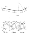
- Figure 4A - 4C are semidiagrammatic view of the catheter of the present invention in the process of being placed in the ostium of the right coronary artery.
- a typical human heart 11 (Fig 1) includes a right ventricle 13, a right atrium 15, and a left ventricle and left atrium (not shown).
- the aorta, labelled 17, arises from the aortic opening of the left ventricle and consists of three parts: the ascending aorta 19, the aortic arch 21, and the descending aorta 23.
- the ascending aorta is located at the ostia for the right coronary artery 25 and the left coronary artery 27.
- the brachiocephalic trunk 29, the left common carotid artery 31, and the left subclavian artery 33 branch off from the aorta.
- Fig 1 Also shown in Fig 1, although of no special relevance to the present invention, are the superior vena cava 35, the inferior vena cava 37, the left pulmonary veins 39, and the left auricle 41.
- a catheter 43 (Figs 2 and 3) of the present invention is specially configured to be inserted through aorta 17 into the ostium of right coronary artery 25. More particularly, catheter 43 is inserted into a suitable artery, such as the femoral artery (not shown) and is directed by means of a conventional guide wire (not shown) to a position in the ascending aorta somewhat above the ostium of right coronary artery 25. The guide wire is then withdrawn and the tip of catheter 43 is moved into the ostium as described below in detail.
- catheter 43 includes a tip portion 45 having a preformed curvature formed therein in a conventional manner.
- This curvature is represented by the angle alpha between the two legs of tip portion 45.
- This angle in Fig 2 is 84.5 degrees, although an angle of approximately ninety degrees is also acceptable.
- This angle is chosen so that the tip portion 45 of catheter 43 will remain securely in the ostium of right coronary artery 25 once the catheter is placed. It is a function of the angle made between the ascending aorta 19 and the right coronary artery 25.
- Proximal from tip portion 45 of catheter 43 is a body portion 47 extending from the tip portion of the proximal end of the catheter.
- Body portion 47 also has a preformed curvature formed therein by conventional means.
- the radius of curvature of the preformed curvature of body portion 47 is much larger than that of tip portion 45.
- the angle beta formed by the legs of body portion 47 is also larger than the corresponding angle alpha of the tip portion. For example, the angle beta is approximately 125 degrees.
- the curvature of the normal ascending aorta 19 in humans although the present invention also works well with abnormal ascending aortas) and is in the opposite direction from the curvature of tip portion 45.
- tip portion 45 may be relatively soft in comparison to body portion 47. This may be accomplished by making catheter 43 in accordance with the teachings of US Patent 4,385,635 to Ruiz.
- catheter 43 has a lumen 49 extending axially through the catheter and terminating at the open distal tip of the catheter. This lumen allows radiopaque dye to be injected through the catheter into the right coronary artery once the catheter is properly placed.
- the angle alpha in Fig 3 is measured at right angles to the legs of tip portion 45 and is taken with respect to a generating circle having a radius R1 which defines the curvature of tip portion 45.
- Radius R1 is preferably five millimeters and the maximum distance tip portion 45 can extend into the right coronary artery with this catheter configuration is approximately ten millimeters. These dimensions are chosen to ensure firm retention of the tip portion in the ostium of the right coronary artery without unduly increasing the possibility of spasm of the artery caused by "diving in" , or over insertion, of tip portion 45.
- tip portion 45 The length and configuration of tip portion 45, as well as the opposite curvature of the body portion from the curvature of the tip portion permits insertion of the tip portion 45 into the ostium 25A only to the desired extent. Moreover, this configuration ensures that the distal end of tip portion 45 remains generally perpendicular to body portion 47 and that the catheter will not -"roll up" during placement.
- the segment of body portion 47 immediately proximate tip portion 45 has a radius of curvature R2 of, for example, approximately 100 millimeters.
- This curvature smoothly changes as one moves proximally away from the tip portion to one having a radius of curvature of approximately 150 millimeters.
- This curvature ends a distance D1 (approximately 130 millimeters) from the distal end of the catheter, and the remaining portion of the catheter over a distance D2 is generally straight.
- distance D2 may be, for example, approximately ninety centimeters.
- catheter 43 The actual placement of catheter 43 is illustrated in Figs 4A - 4C.
- the tip portion 45 of catheter 43 is inserted through the aorta to a position within the ascending aorta 19 where the distal tip of the catheter is disposed above the ostium 25A of right coronary artery 25 with the end of the tip touching the inner wall of ascending aorta 19 above the ostium.
- This insertion is preferably performed using a guide wire that straightens the preformed curvature of tip portion 45 during insertion through the descending aorta and aortic arch into the ascending aorta.
- the guide wire is retracted to allow tip portion 45 to assume its preformed curvature.
- the tip portion 45 is then oriented so that the end of the tip portion is pointed toward and in contact with the right inner wall 20 of the ascending aorta, as shown in Fig 4A for example.
- the tip portion is then moved downwardly as shown in Figs 4B and 4C, contacting the right inner wall 20 of the ascending aorta, by physically applying a torque to the proximal end of the catheter to cause the catheter tip to rotate somewhat, while injecting small amounts of radiopaque dye, until the rotatory motion and injections reveal that the tip portion 45 has reached the ostium 25A (Fig 4C).
- tip portion 45 is biassed into the ostium by the body portion of catheter 43. More particularly, body portion 47 includes a first segment 51 and a second segment 53.
- second segment 53 as shown in Fig 4C is deformed because no part of body portion 47 has a curvature as great as that of the aortic arch in which second segment 53 is disposed.
- Body portion 47 is resilient, however, so the deformation caused by aortic arch 21 causes tip portion 45 to be forced to the left as shown in Fig 4C so that it remains firmly in place in ostium 25A.
- catheter 43 there is no need for the user to accurately rotate the catheter to ensure proper placement. Nor is there any significant danger of the catheter diving into the right coronary artery since the configuration of the tip portion prevents over-insertion of the catheter.
Abstract
Description
- This invention relates to catheters useful in cardiac angiography and more particularly to such catheters especially suited for the injection of a radiopaque dye into the right coronary artery.
- Coronary angiography or arteriography involves the insertion of a hollow catheter into an artery at a remote point such as an arm or leg. The catheter is typically guided to the heart itself by a guide wire over which the catheter rides. The guide wire is removed before use of the catheter. Once the catheter is properly placed, a radiopaque dye is injected through the lumen of the catheter so that an x-ray machine or fluoroscope may be used to determine the physical condition of the particular part of the heart under study.
- The exact placement of the tip of the catheter in the heart depends upon the type of coronary angiography to be performed. For example. in non-selective angiography the tip of the catheter is positioned in the aorta itself so that both the left and right coronary arteries can be simultaneously injected with radiopaque dye. In selective angiography, on the other hand, the tip of the catheter is actually placed in the ostium of the coronary artery which one wishes to study, in this case the right coronary artery, and the radiopaque dye is injected directly into that artery. Selective angiography produces pictures having sharp images which are extremely helpful in diagnosing and treating coronary diseases.
- Heretofore, some catheters used for selective right coronary artery angiography have not always retained their positions in the ostium of the right coronary artery during the procedure. As a result the radiopaque dye was not wholly injected into the right coronary artery and the images obtained were not as satisfactory as could be desired. While some catheters fall or pop out of the ostium, others are difficult to insert properly into the ostium initially. In addition, some prior catheters have been known to dive too far into the right coronary artery itself, which can cause a spasm of the artery.
- It is also important that the catheter be made of the proper materials. Although a certain hardness and rigidity is desired to maintain the catheter in position in the ostium once the tip is inserted therein, a catheter which is too rigid is difficult to position properly. Moreover, a relatively hard tip on the catheter can result in the dislodging of plaque from the vessel walls, which is not desirable. Several catheters have been proposed or developed to solve some of the above difficulties. For example. US Patent 3,935,857 to Co discloses a cardiac catheter which is alleged to be useful in both right coronary and left coronary selective arteriography. On the other hand, Dr Melvin P Judkins in Chapter 7 of Coronary Arteriography and Angioplasty (McGraw-Hill) discloses differently shaped catheters for right coronary and left coronary selective arteriography. The Judkins right coronary catheter has a preformed curvature which is designed to assist in the placement of the catheter tip in the ostium of the right coronary artery and to help hold the tip in place during the procedure. Because of the particular configuration chosen for the Judkins right coronary catheter, it is necessary for the catheter to be made in a number of different sizes to accommodate different patients. It is also necessary in using the Judkins right coronary catheter to physically rotate the catheter approximately 180 degrees once the catheter is in the heart to make it assume the proper position to enter the ostium of the right coronary artery. As Dr Judkins points out in the aforementioned chapter, this rotation must be done very slowly and commonly gives rise to error in placement of the catheter.
- The present invention relates to a catheter particularly suited for use in selective arteriography of the right coronary artery.
- A preferred embodiment of the catheter of the present invention has an improved ability to stay in place in the ostium once placed there. Also it may be easy to manipulate, may reduce the possibility of spasm of the right coronary artery and may minimize trauma to the heart itself. The catheter may reduce or eliminate the need to select the proper size catheter to use with a particular patient. The catheter may be less dependent upon operator technique for proper placement of the catheter in the ostium of the right coronary artery and may be less prone to error in placement.
- According to the invention there is provided a right coronary artery angiographic catheter characterised in that it comprises:
a relatively soft, distal tip portion (45), the tip portion having a preformed curvature in a first direction;
a body portion extending proximally from the tip portion, the body portion having a preformed curvature in a second direction, opposite the direction of curvature of the tip portion, the body portion being resilient so that it tends to assume its preformed curvature;
a lumen extending from the distal end of the tip portion through at least a substantial part of the body portion, the lumen being suitable for the injection of angiographic dye therethrough to exit from the distal end of the tip portion of the catheter;
the body portion having an amount of curvature in a second segment which is less than the amount of curvature of the aortic arch of a human being, the second segment being that part of the body portion disposed in the aortic arch when the tip portion is disposed in the ostium of the right coronary artery so that the body portion of the catheter is resiliently deformed where it passes through the aortic arch, the deformation resulting in the biassing of the tip portion of the catheter into the ostium of the right coronary artery when in use. - The shape of the tip portion is preferably such as to prevent spasm of the right coronary artery when the tip portion is inserted in the ostium thereof. The tip portion of the catheter may extend in the direction of the right coronary artery approximately ten millimeters when in use. The tip portion curvature preferably includes an approximately ninety degree bend which can have an inner radius of approximately five millimeters. Preferably the radius of curvature for the body portion exceeds by at least an order of magnitude, eg by a factor of approximately twenty, the radius of curvature of the tip portion.
- The method of using the catheter of the present invention includes the steps of inserting the preformed, hollow catheter through the aorta to a predetermined position above the ostium of the right coronary artery and orienting the preformed catheter so that the curvature of the body portion of the catheter corresponds in direction to the curvature of the aortic arch with the tip portion of the catheter disposed above the ostium of the right coronary artery and the distal end of the tip portion touching the wall of the ascending aorta. Then the tip portion of the catheter is moved down the wall of the ascending aorta (eg in a rotatory manner using the catheter torque and applying small injections of radiopaque dye) until the ostium of the right coronary artery is located and reached.
- There the tip portion of the catheter is biassed into the ostium of the right coronary artery as a result of the tendency of the body portion of the catheter to assume its preformed curvature from which it has been deformed in passing through the aortic arch. Once the catheter is placed, an arteriographic dye is injected through the hollow catheter into the right coronary artery.
- In the above method the catheter is preferably inserted into the ascending aorta in its oriented position with the curvature of the body portion corresponding in direction to the curvature of the aortic arch and the distal end of the tip portion touching the wall of the ascending aorta so that the tip portion may enter the ostium of the right coronary artery without being substantially rotated from its initial oriented position.
- In the inserting step the catheter may be guided along the aorta with a guide wire disposed in the lumen of the hollow catheter until the catheter reaches the vicinity of the top of the aortic arch, and then the guide wire may be removed before the tip portion of the catheter moves down the wall of the ascending aorta.
- The invention also relates to a method of performing a selective coronary arteriography on the right coronary artery of a human being comprising the steps of:
inserting a catheter through the aortic arch into the ascending aorta of the human being such that a tip portion of the catheter is disposed above the ostium of the right coronary artery;
orienting the catheter so that an open distal end of the catheter tip portion is pointed toward and in contact with the inner wall of the ascending aorta;
advancing the catheter tip portion toward the ostium of the right coronary artery by moving the distal end along and contacting the inner wall while biassing the tip portion of the catheter toward the inner wall of the ascending aorta with resilience of the catheter body; and
inserting the distal open end of the tip portion in the ostium of the right coronary artery responsive to the advancing and biassing steps. - The invention is described by way of example only in the following description of a preferred embodiment shown with reference to the accompanying drawings in which Figure 1 is a perspective view of the human heart illustrating the relative placement of the right coronary artery, the ascending aorta, and the aortic arch;
Figure 2 is a side elevation of the catheter of the present invention illustrating the overall configuration thereof;
Figure 3 is a cross-sectional view of the catheter of the present invention; and
Figure 4A - 4C are semidiagrammatic view of the catheter of the present invention in the process of being placed in the ostium of the right coronary artery. - Similar reference characters indicate similar parts throughout the several views of the drawings.
- A typical human heart 11 (Fig 1) includes a right ventricle 13, a
right atrium 15, and a left ventricle and left atrium (not shown). The aorta, labelled 17, arises from the aortic opening of the left ventricle and consists of three parts: theascending aorta 19, theaortic arch 21, and thedescending aorta 23. At the base of the ascending aorta is located the ostia for the rightcoronary artery 25 and the leftcoronary artery 27. At the top of the aortic arch thebrachiocephalic trunk 29, the leftcommon carotid artery 31, and the leftsubclavian artery 33 branch off from the aorta. - Also shown in Fig 1, although of no special relevance to the present invention, are the
superior vena cava 35, theinferior vena cava 37, the leftpulmonary veins 39, and theleft auricle 41. - A catheter 43 (Figs 2 and 3) of the present invention is specially configured to be inserted through
aorta 17 into the ostium of rightcoronary artery 25. More particularly,catheter 43 is inserted into a suitable artery, such as the femoral artery (not shown) and is directed by means of a conventional guide wire (not shown) to a position in the ascending aorta somewhat above the ostium of rightcoronary artery 25. The guide wire is then withdrawn and the tip ofcatheter 43 is moved into the ostium as described below in detail. - As can be seen from Fig 2,
catheter 43 includes atip portion 45 having a preformed curvature formed therein in a conventional manner. This curvature is represented by the angle alpha between the two legs oftip portion 45. This angle in Fig 2 is 84.5 degrees, although an angle of approximately ninety degrees is also acceptable. This angle is chosen so that thetip portion 45 ofcatheter 43 will remain securely in the ostium of rightcoronary artery 25 once the catheter is placed. It is a function of the angle made between the ascendingaorta 19 and the rightcoronary artery 25. - Proximal from
tip portion 45 ofcatheter 43 is abody portion 47 extending from the tip portion of the proximal end of the catheter.Body portion 47 also has a preformed curvature formed therein by conventional means. As can be seen in Figs 2 and 3, the radius of curvature of the preformed curvature ofbody portion 47 is much larger than that oftip portion 45. Moreover, the angle beta formed by the legs ofbody portion 47 is also larger than the corresponding angle alpha of the tip portion. For example, the angle beta is approximately 125 degrees. The curvature of thenormal ascending aorta 19 in humans (although the present invention also works well with abnormal ascending aortas) and is in the opposite direction from the curvature oftip portion 45. - It is preferred that
tip portion 45 may be relatively soft in comparison tobody portion 47. This may be accomplished by makingcatheter 43 in accordance with the teachings of US Patent 4,385,635 to Ruiz. - As can be seen in Fig 3,
catheter 43 has alumen 49 extending axially through the catheter and terminating at the open distal tip of the catheter. This lumen allows radiopaque dye to be injected through the catheter into the right coronary artery once the catheter is properly placed. - The angle alpha in Fig 3 is measured at right angles to the legs of
tip portion 45 and is taken with respect to a generating circle having a radius R1 which defines the curvature oftip portion 45. Radius R1 is preferably five millimeters and the maximumdistance tip portion 45 can extend into the right coronary artery with this catheter configuration is approximately ten millimeters. These dimensions are chosen to ensure firm retention of the tip portion in the ostium of the right coronary artery without unduly increasing the possibility of spasm of the artery caused by "diving in" , or over insertion, oftip portion 45. The length and configuration oftip portion 45, as well as the opposite curvature of the body portion from the curvature of the tip portion permits insertion of thetip portion 45 into theostium 25A only to the desired extent. Moreover, this configuration ensures that the distal end oftip portion 45 remains generally perpendicular tobody portion 47 and that the catheter will not -"roll up" during placement. - The segment of
body portion 47 immediatelyproximate tip portion 45 has a radius of curvature R2 of, for example, approximately 100 millimeters. This curvature smoothly changes as one moves proximally away from the tip portion to one having a radius of curvature of approximately 150 millimeters. This curvature ends a distance D1 (approximately 130 millimeters) from the distal end of the catheter, and the remaining portion of the catheter over a distance D2 is generally straight. For acatheter 43 designed for femoral entry, distance D2 may be, for example, approximately ninety centimeters. - The actual placement of
catheter 43 is illustrated in Figs 4A - 4C. As shown in Fig 4A, thetip portion 45 ofcatheter 43 is inserted through the aorta to a position within the ascendingaorta 19 where the distal tip of the catheter is disposed above theostium 25A of rightcoronary artery 25 with the end of the tip touching the inner wall of ascendingaorta 19 above the ostium. This insertion is preferably performed using a guide wire that straightens the preformed curvature oftip portion 45 during insertion through the descending aorta and aortic arch into the ascending aorta. The guide wire is retracted to allowtip portion 45 to assume its preformed curvature. Thetip portion 45 is then oriented so that the end of the tip portion is pointed toward and in contact with the rightinner wall 20 of the ascending aorta, as shown in Fig 4A for example. The tip portion is then moved downwardly as shown in Figs 4B and 4C, contacting the rightinner wall 20 of the ascending aorta, by physically applying a torque to the proximal end of the catheter to cause the catheter tip to rotate somewhat, while injecting small amounts of radiopaque dye, until the rotatory motion and injections reveal that thetip portion 45 has reached theostium 25A (Fig 4C). At this point,tip portion 45 is biassed into the ostium by the body portion ofcatheter 43. More particularly,body portion 47 includes afirst segment 51 and asecond segment 53. As can be seen by examining Figs 3 and 4C,second segment 53 as shown in Fig 4C is deformed because no part ofbody portion 47 has a curvature as great as that of the aortic arch in whichsecond segment 53 is disposed.Body portion 47 is resilient, however, so the deformation caused by aortic arch 21 causes tipportion 45 to be forced to the left as shown in Fig 4C so that it remains firmly in place inostium 25A. - Note that with
catheter 43, there is no need for the user to accurately rotate the catheter to ensure proper placement. Nor is there any significant danger of the catheter diving into the right coronary artery since the configuration of the tip portion prevents over-insertion of the catheter. - Numerous variations, within the scope of the appended claims, will be apparent to those skilled in the art in light of the foregoing description and accompanying drawings. These variations are merely illustrative.
Claims (7)
a relatively soft, distal tip portion (45), the tip portion having a preformed curvature in a first direction;
a body portion (47) extending proximally from the tip portion, the body portion having a preformed curvature in a second direction, opposite the direction of curvature of the tip portion, the body portion being resilient so that it tends to assume its preformed curvature;
a lumen (49) extending from the distal end of the tip portion through at least a substantial part of the body portion, the lumen being suitable for the injection of angiographic dye therethrough to exit from the distal end of the tip portion of the catheter;
the body portion (47) having an amount of curvature in a second segment which is less than the amount of curvature of the aortic arch of a human being, the second segment being that part of the body portion disposed in the aortic arch when the tip portion is disposed in the ostium of the right coronary artery so that the body portion of the catheter is resiliently deformed where it passes through the artic arch, the deformation resulting in the biassing of the tip portion of the catheter into the ostium of the right coronary artery when in use.
Priority Applications (1)
| Application Number | Priority Date | Filing Date | Title |
|---|---|---|---|
| AT88312198T ATE96682T1 (en) | 1988-01-06 | 1988-12-22 | CATHETER. |
Applications Claiming Priority (2)
| Application Number | Priority Date | Filing Date | Title |
|---|---|---|---|
| US07/141,208 US4883058A (en) | 1988-01-06 | 1988-01-06 | Right coronary angiographic method |
| US141208 | 1988-01-06 |
Publications (3)
| Publication Number | Publication Date |
|---|---|
| EP0323738A2 true EP0323738A2 (en) | 1989-07-12 |
| EP0323738A3 EP0323738A3 (en) | 1990-05-23 |
| EP0323738B1 EP0323738B1 (en) | 1993-11-03 |
Family
ID=22494662
Family Applications (1)
| Application Number | Title | Priority Date | Filing Date |
|---|---|---|---|
| EP88312198A Expired - Lifetime EP0323738B1 (en) | 1988-01-06 | 1988-12-22 | Catheters |
Country Status (7)
| Country | Link |
|---|---|
| US (1) | US4883058A (en) |
| EP (1) | EP0323738B1 (en) |
| JP (1) | JPH01238872A (en) |
| AT (1) | ATE96682T1 (en) |
| CA (1) | CA1336059C (en) |
| DE (1) | DE3885439T2 (en) |
| ES (1) | ES2047564T3 (en) |
Cited By (13)
| Publication number | Priority date | Publication date | Assignee | Title |
|---|---|---|---|---|
| WO1992019307A1 (en) * | 1991-04-24 | 1992-11-12 | Myers Gene E | Aortic branch internal thoracic artery catheter |
| EP0531946A1 (en) * | 1991-09-11 | 1993-03-17 | Namic Caribe, Inc. | Coronary catheter |
| WO1993014802A1 (en) * | 1992-01-28 | 1993-08-05 | Nesto Richard W | Left coronary guiding catheter |
| WO1993021983A1 (en) * | 1992-05-01 | 1993-11-11 | Jan Voda | Preformed coronary artery guide catheter |
| FR2715827A1 (en) * | 1994-02-07 | 1995-08-11 | Braun Celsa Sa | Implantable medical device in the body of a patient, axially stabilized rod, rod and curved piece for this purpose and their method of production. |
| EP0714672A2 (en) * | 1994-11-03 | 1996-06-05 | Daig Corporation | Guiding introducer system for use in right atrium |
| EP0727238A2 (en) * | 1995-02-14 | 1996-08-21 | Daig Corporation | Guiding introducer system for use in the treatment of accessory pathways around the mitral valve using a retrograde approach |
| WO1997002066A1 (en) * | 1995-06-30 | 1997-01-23 | Medtronic, Inc. | Improved multi-purpose curve |
| US5885259A (en) * | 1996-01-19 | 1999-03-23 | Scimed Life Systems, Inc. | Increasing radius curve catheter |
| US6083213A (en) * | 1991-01-23 | 2000-07-04 | Voda; Jan | Angioplasty guide catheter |
| US6595983B2 (en) | 2000-12-07 | 2003-07-22 | Jan K. Voda | Guide or diagnostic catheter for right coronary artery |
| US7867218B1 (en) | 2004-02-24 | 2011-01-11 | Voda Heart Technology, Llc | Steerable catheter for right coronary artery |
| US10252023B2 (en) | 2013-01-11 | 2019-04-09 | C. R. Bard, Inc. | Curved catheter and methods for making same |
Families Citing this family (42)
| Publication number | Priority date | Publication date | Assignee | Title |
|---|---|---|---|---|
| US4973306A (en) * | 1988-01-06 | 1990-11-27 | Sherwood Medical Company | Method of performing right coronary artery angiography |
| US5348545A (en) * | 1990-08-21 | 1994-09-20 | Advanced Cardiovascular Systems, Inc. | Guiding catheter for the right coronary artery |
| DE568624T1 (en) * | 1991-01-23 | 1994-09-22 | Jan Voda | CONSTRUCTION OF A GUIDE CATHETER. |
| US5215540A (en) * | 1992-01-31 | 1993-06-01 | St. Jude Medical, Inc. | Right coronary catheter |
| US5538512A (en) * | 1993-02-25 | 1996-07-23 | Zenzon; Wendy J. | Lubricious flow directed catheter |
| US5336205A (en) * | 1993-02-25 | 1994-08-09 | Target Therapeutics, Inc. | Flow directed catheter |
| US5536247A (en) * | 1993-06-10 | 1996-07-16 | Scimed Life Systems, Inc. | Method of treating cardiac conduction defects |
| US5423772A (en) * | 1993-08-13 | 1995-06-13 | Daig Corporation | Coronary sinus catheter |
| US5643231A (en) * | 1993-08-13 | 1997-07-01 | Daig Corporation | Coronary sinus catheter |
| US5984909A (en) * | 1993-08-13 | 1999-11-16 | Daig Corporation | Coronary sinus catheter |
| US6001085A (en) * | 1993-08-13 | 1999-12-14 | Daig Corporation | Coronary sinus catheter |
| US5846223A (en) * | 1993-11-03 | 1998-12-08 | Daig Corporation | Diagnosis and treatment of atrial flutter in the right atrium |
| US5497774A (en) * | 1993-11-03 | 1996-03-12 | Daig Corporation | Guiding introducer for left atrium |
| US5814027A (en) * | 1993-11-03 | 1998-09-29 | Daig Corporation | Guiding introducer used for medical procedures within the right ventricle associated with the right ventricular outflow track |
| US5656028A (en) * | 1993-11-03 | 1997-08-12 | Daig Corporation | Process for the nonsurgical mapping and/or treatment of ectopic atrial tachycardia using a guiding introducer |
| US5575766A (en) * | 1993-11-03 | 1996-11-19 | Daig Corporation | Process for the nonsurgical mapping and treatment of atrial arrhythmia using catheters guided by shaped guiding introducers |
| US5722400A (en) * | 1995-02-16 | 1998-03-03 | Daig Corporation | Guiding introducers for use in the treatment of left ventricular tachycardia |
| US5564440A (en) * | 1993-11-03 | 1996-10-15 | Daig Corporation | Method for mopping and/or ablation of anomalous conduction pathways |
| US5640955A (en) * | 1995-02-14 | 1997-06-24 | Daig Corporation | Guiding introducers for use in the treatment of accessory pathways around the mitral valve using a retrograde approach |
| US5427119A (en) * | 1993-11-03 | 1995-06-27 | Daig Corporation | Guiding introducer for right atrium |
| US5833673A (en) * | 1994-11-02 | 1998-11-10 | Daig Corporation | Guiding introducer system for use in the treatment of left ventricular tachycardia |
| US5814029A (en) * | 1994-11-03 | 1998-09-29 | Daig Corporation | Guiding introducer system for use in ablation and mapping procedures in the left ventricle |
| US6540755B2 (en) | 1995-02-14 | 2003-04-01 | Daig Corporation | Guiding introducers for use in the treatment of accessory pathways around the mitral valve using a retrograde approach |
| US5730733A (en) * | 1995-06-01 | 1998-03-24 | Scimed Life Systems, Inc. | Flow assisted catheter |
| US5971974A (en) * | 1995-09-06 | 1999-10-26 | Schneider ( Usa ) Inc | Left coronary artery catheter |
| US5899892A (en) * | 1996-05-31 | 1999-05-04 | Scimed Life Systems, Inc. | Catheter having distal fiber braid |
| US5846229A (en) * | 1996-05-31 | 1998-12-08 | Scimed Life Systems, Inc. | Catheter for the right coronary artery |
| US6251109B1 (en) * | 1997-06-27 | 2001-06-26 | Daig Corporation | Process and device for the treatment of atrial arrhythmia |
| US5938660A (en) * | 1997-06-27 | 1999-08-17 | Daig Corporation | Process and device for the treatment of atrial arrhythmia |
| WO1999025411A1 (en) | 1997-11-18 | 1999-05-27 | Daig Corporation | Catheter guiding introducers for use in pediatric hearts |
| US6200315B1 (en) | 1997-12-18 | 2001-03-13 | Medtronic, Inc. | Left atrium ablation catheter |
| US5916209A (en) | 1997-12-24 | 1999-06-29 | Mick; Matthew J. | Coronary catheters for use in a transradial catheterization |
| US6193705B1 (en) | 1998-10-28 | 2001-02-27 | Scimed Life Systems, Inc. | Flow assisted catheter |
| US20040015152A1 (en) * | 2002-05-20 | 2004-01-22 | Day Ronald W. | Reducing torque needed to perform a cardiovascular procedure |
| AU2004229523B2 (en) | 2003-04-14 | 2008-09-25 | Cook Medical Technologies Llc | Large diameter delivery catheter/sheath |
| US11000670B2 (en) | 2003-04-28 | 2021-05-11 | Cook Medical Technologies Llc | Flexible sheath with varying durometer |
| US7789877B2 (en) | 2003-07-02 | 2010-09-07 | St. Jude Medical, Atrial Fibrillation Division, Inc. | Ablation catheter electrode arrangement |
| US7234225B2 (en) * | 2003-09-22 | 2007-06-26 | St. Jude Medical, Atrial Fibrillation Division, Inc. | Method for manufacturing medical device having embedded traces and formed electrodes |
| US8147486B2 (en) | 2003-09-22 | 2012-04-03 | St. Jude Medical, Atrial Fibrillation Division, Inc. | Medical device with flexible printed circuit |
| US7229437B2 (en) | 2003-09-22 | 2007-06-12 | St. Jude Medical, Atrial Fibrillation Division, Inc. | Medical device having integral traces and formed electrodes |
| DE602007004718D1 (en) | 2006-03-31 | 2010-03-25 | Bard Inc C R | Catheter with arched transition area |
| US11027093B2 (en) * | 2016-12-08 | 2021-06-08 | Sanford Health | Slide guide catheter and methods for use thereof |
Citations (4)
| Publication number | Priority date | Publication date | Assignee | Title |
|---|---|---|---|---|
| DE2627851A1 (en) * | 1975-06-23 | 1977-01-13 | Siemens Elema Ab | CATHETER FOR SELECTIVE CORONARY ARTERIOGRAPHY OF THE LEFT CORONAR ARTERY |
| EP0063859A2 (en) * | 1981-03-06 | 1982-11-03 | American Hospital Supply Corporation | Infusion catheter |
| EP0273618A2 (en) * | 1986-12-23 | 1988-07-06 | BAXTER INTERNATIONAL INC. (a Delaware corporation) | Soft tip catheter |
| US4784639A (en) * | 1987-07-06 | 1988-11-15 | Patel Piyush V | Catheter and method of inserting catheter |
Family Cites Families (9)
| Publication number | Priority date | Publication date | Assignee | Title |
|---|---|---|---|---|
| US3419010A (en) * | 1966-01-17 | 1968-12-31 | Cordis Corp | Catheter |
| CA930636A (en) * | 1970-04-29 | 1973-07-24 | Cardinal Roland | Catheters and method and mold for making same |
| US3935857A (en) * | 1974-07-31 | 1976-02-03 | Co Eddy D | Cardiac catheter |
| US4033331A (en) * | 1975-07-17 | 1977-07-05 | Guss Stephen B | Cardiac catheter and method of using same |
| US4292976A (en) * | 1979-08-08 | 1981-10-06 | Banka Vidya S | Right ventricular injection catheter; right ventricular angiographic method; and method of monitoring septal wall motion |
| US4279252A (en) * | 1979-08-24 | 1981-07-21 | Martin Michael T | X-ray scaling catheter |
| JPS56124449U (en) * | 1980-02-20 | 1981-09-22 | ||
| US4385635A (en) * | 1980-04-25 | 1983-05-31 | Ruiz Oscar F | Angiographic catheter with soft tip end |
| US4563181A (en) * | 1983-02-18 | 1986-01-07 | Mallinckrodt, Inc. | Fused flexible tip catheter |
-
1988
- 1988-01-06 US US07/141,208 patent/US4883058A/en not_active Expired - Lifetime
- 1988-12-22 EP EP88312198A patent/EP0323738B1/en not_active Expired - Lifetime
- 1988-12-22 CA CA000586844A patent/CA1336059C/en not_active Expired - Fee Related
- 1988-12-22 AT AT88312198T patent/ATE96682T1/en not_active IP Right Cessation
- 1988-12-22 ES ES88312198T patent/ES2047564T3/en not_active Expired - Lifetime
- 1988-12-22 DE DE88312198T patent/DE3885439T2/en not_active Expired - Lifetime
- 1988-12-28 JP JP63332685A patent/JPH01238872A/en active Granted
Patent Citations (4)
| Publication number | Priority date | Publication date | Assignee | Title |
|---|---|---|---|---|
| DE2627851A1 (en) * | 1975-06-23 | 1977-01-13 | Siemens Elema Ab | CATHETER FOR SELECTIVE CORONARY ARTERIOGRAPHY OF THE LEFT CORONAR ARTERY |
| EP0063859A2 (en) * | 1981-03-06 | 1982-11-03 | American Hospital Supply Corporation | Infusion catheter |
| EP0273618A2 (en) * | 1986-12-23 | 1988-07-06 | BAXTER INTERNATIONAL INC. (a Delaware corporation) | Soft tip catheter |
| US4784639A (en) * | 1987-07-06 | 1988-11-15 | Patel Piyush V | Catheter and method of inserting catheter |
Cited By (25)
| Publication number | Priority date | Publication date | Assignee | Title |
|---|---|---|---|---|
| US6475195B1 (en) | 1991-01-23 | 2002-11-05 | Jan Voda | Angioplasty guide catheter |
| US6083213A (en) * | 1991-01-23 | 2000-07-04 | Voda; Jan | Angioplasty guide catheter |
| WO1992019307A1 (en) * | 1991-04-24 | 1992-11-12 | Myers Gene E | Aortic branch internal thoracic artery catheter |
| EP0531946A1 (en) * | 1991-09-11 | 1993-03-17 | Namic Caribe, Inc. | Coronary catheter |
| US5306262A (en) * | 1991-09-11 | 1994-04-26 | Namic Caribe, Inc. | Coronary catheter |
| US5957911A (en) * | 1992-01-28 | 1999-09-28 | Advanced Cardiovascular Systems, Inc. | Left coronary guiding catheter |
| WO1993014802A1 (en) * | 1992-01-28 | 1993-08-05 | Nesto Richard W | Left coronary guiding catheter |
| US6120495A (en) * | 1992-05-01 | 2000-09-19 | Voda; Jan | Preformed coronary artery guide catheter |
| US6558368B1 (en) | 1992-05-01 | 2003-05-06 | Jan Voda | Preformed coronary artery guide catheter |
| WO1993021983A1 (en) * | 1992-05-01 | 1993-11-11 | Jan Voda | Preformed coronary artery guide catheter |
| US6110163A (en) * | 1992-05-01 | 2000-08-29 | Voda; Jan | Preformed coronary artery guide catheter |
| US5868700A (en) * | 1992-05-01 | 1999-02-09 | Voda; Jan | Preformed coronary artery guide catheter |
| EP0670150A1 (en) * | 1994-02-07 | 1995-09-06 | B. BRAUN CELSA, Société Anonyme | Axially stabilized endovascular bloodfilter |
| FR2715827A1 (en) * | 1994-02-07 | 1995-08-11 | Braun Celsa Sa | Implantable medical device in the body of a patient, axially stabilized rod, rod and curved piece for this purpose and their method of production. |
| EP0714672A2 (en) * | 1994-11-03 | 1996-06-05 | Daig Corporation | Guiding introducer system for use in right atrium |
| EP0714672A3 (en) * | 1994-11-03 | 1998-07-01 | Daig Corporation | Guiding introducer system for use in right atrium |
| EP0727238A3 (en) * | 1995-02-14 | 1997-05-21 | Daig Corp | Guiding introducer system for use in the treatment of accessory pathways around the mitral valve using a retrograde approach |
| EP0727238A2 (en) * | 1995-02-14 | 1996-08-21 | Daig Corporation | Guiding introducer system for use in the treatment of accessory pathways around the mitral valve using a retrograde approach |
| WO1997002066A1 (en) * | 1995-06-30 | 1997-01-23 | Medtronic, Inc. | Improved multi-purpose curve |
| US5941872A (en) * | 1996-01-19 | 1999-08-24 | Scimed Life Systems, Inc. | Method of using an increasing radius curve catheter |
| US5885259A (en) * | 1996-01-19 | 1999-03-23 | Scimed Life Systems, Inc. | Increasing radius curve catheter |
| US6595983B2 (en) | 2000-12-07 | 2003-07-22 | Jan K. Voda | Guide or diagnostic catheter for right coronary artery |
| US7867218B1 (en) | 2004-02-24 | 2011-01-11 | Voda Heart Technology, Llc | Steerable catheter for right coronary artery |
| US10252023B2 (en) | 2013-01-11 | 2019-04-09 | C. R. Bard, Inc. | Curved catheter and methods for making same |
| US11633566B2 (en) | 2013-01-11 | 2023-04-25 | C. R. Bard, Inc. | Curved catheter and methods for making same |
Also Published As
| Publication number | Publication date |
|---|---|
| ATE96682T1 (en) | 1993-11-15 |
| DE3885439T2 (en) | 1994-03-17 |
| JPH0459916B2 (en) | 1992-09-24 |
| EP0323738B1 (en) | 1993-11-03 |
| DE3885439D1 (en) | 1993-12-09 |
| EP0323738A3 (en) | 1990-05-23 |
| US4883058A (en) | 1989-11-28 |
| JPH01238872A (en) | 1989-09-25 |
| ES2047564T3 (en) | 1994-03-01 |
| CA1336059C (en) | 1995-06-27 |
Similar Documents
| Publication | Publication Date | Title |
|---|---|---|
| EP0323738B1 (en) | Catheters | |
| US5016640A (en) | Angiographic catheter for use in the right coronary artery | |
| US5195990A (en) | Coronary catheter | |
| US4033331A (en) | Cardiac catheter and method of using same | |
| EP0829270B1 (en) | Preshaped catheter for angiocardiography | |
| US6083213A (en) | Angioplasty guide catheter | |
| US4973306A (en) | Method of performing right coronary artery angiography | |
| US6656166B2 (en) | Guiding introducer for introducing medical devices into the coronary sinus and process for using same | |
| US5299574A (en) | Method and apparatus for selective coronary arteriography | |
| EP0755278B1 (en) | Coronary sinus catheter introducer system | |
| US4976691A (en) | Topless catheters | |
| EP0898480B1 (en) | Increasing radius curve catheter | |
| US5098412A (en) | Support system for catheter | |
| US5868700A (en) | Preformed coronary artery guide catheter | |
| US5769821A (en) | Catheter tip retainer | |
| US5957911A (en) | Left coronary guiding catheter | |
| US20060259111A1 (en) | Lead and catheter assembly | |
| EP0963179B1 (en) | Improved device for removing fibrin sheaths from catheters | |
| WO1992012754A1 (en) | Guide catheter construction | |
| JPH021294A (en) | Freely extendable guide wire | |
| EP0652026A1 (en) | Flexible catheter guidewire | |
| JP4668368B2 (en) | Right coronary catheter | |
| EP0351206B1 (en) | A central venous catheter | |
| JPH0464273B2 (en) | ||
| Feldman et al. | An improved catheter design for crossing stenosed aortic valves |
Legal Events
| Date | Code | Title | Description |
|---|---|---|---|
| PUAI | Public reference made under article 153(3) epc to a published international application that has entered the european phase |
Free format text: ORIGINAL CODE: 0009012 |
|
| AK | Designated contracting states |
Kind code of ref document: A2 Designated state(s): AT BE CH DE ES FR GB GR IT LI LU NL SE |
|
| PUAL | Search report despatched |
Free format text: ORIGINAL CODE: 0009013 |
|
| AK | Designated contracting states |
Kind code of ref document: A3 Designated state(s): AT BE CH DE ES FR GB GR IT LI LU NL SE |
|
| 17P | Request for examination filed |
Effective date: 19901109 |
|
| 17Q | First examination report despatched |
Effective date: 19920214 |
|
| GRAA | (expected) grant |
Free format text: ORIGINAL CODE: 0009210 |
|
| RAP1 | Party data changed (applicant data changed or rights of an application transferred) |
Owner name: NAMIC U.S.A. CORPORATION |
|
| AK | Designated contracting states |
Kind code of ref document: B1 Designated state(s): AT BE CH DE ES FR GB GR IT LI LU NL SE |
|
| REF | Corresponds to: |
Ref document number: 96682 Country of ref document: AT Date of ref document: 19931115 Kind code of ref document: T |
|
| REF | Corresponds to: |
Ref document number: 3885439 Country of ref document: DE Date of ref document: 19931209 |
|
| ITF | It: translation for a ep patent filed |
Owner name: MODIANO & ASSOCIATI S.R.L. |
|
| ET | Fr: translation filed | ||
| REG | Reference to a national code |
Ref country code: ES Ref legal event code: FG2A Ref document number: 2047564 Country of ref document: ES Kind code of ref document: T3 |
|
| EPTA | Lu: last paid annual fee | ||
| REG | Reference to a national code |
Ref country code: GR Ref legal event code: FG4A Free format text: 3010605 |
|
| PLBE | No opposition filed within time limit |
Free format text: ORIGINAL CODE: 0009261 |
|
| STAA | Information on the status of an ep patent application or granted ep patent |
Free format text: STATUS: NO OPPOSITION FILED WITHIN TIME LIMIT |
|
| 26N | No opposition filed | ||
| EAL | Se: european patent in force in sweden |
Ref document number: 88312198.0 |
|
| REG | Reference to a national code |
Ref country code: CH Ref legal event code: NV Representative=s name: E. BLUM & CO. PATENTANWAELTE |
|
| REG | Reference to a national code |
Ref country code: CH Ref legal event code: PFA Free format text: NAMIC U.S.A. CORPORATION TRANSFER- SCHNEIDER/NAMIC |
|
| NLT1 | Nl: modifications of names registered in virtue of documents presented to the patent office pursuant to art. 16 a, paragraph 1 |
Owner name: SCHNEIDER/NAMIC |
|
| REG | Reference to a national code |
Ref country code: FR Ref legal event code: CD |
|
| PGFP | Annual fee paid to national office [announced via postgrant information from national office to epo] |
Ref country code: LU Payment date: 19980925 Year of fee payment: 11 |
|
| PGFP | Annual fee paid to national office [announced via postgrant information from national office to epo] |
Ref country code: BE Payment date: 19981008 Year of fee payment: 11 |
|
| PGFP | Annual fee paid to national office [announced via postgrant information from national office to epo] |
Ref country code: GR Payment date: 19981030 Year of fee payment: 11 |
|
| PGFP | Annual fee paid to national office [announced via postgrant information from national office to epo] |
Ref country code: CH Payment date: 19981110 Year of fee payment: 11 |
|
| PGFP | Annual fee paid to national office [announced via postgrant information from national office to epo] |
Ref country code: ES Payment date: 19981222 Year of fee payment: 11 |
|
| PG25 | Lapsed in a contracting state [announced via postgrant information from national office to epo] |
Ref country code: LU Free format text: LAPSE BECAUSE OF NON-PAYMENT OF DUE FEES Effective date: 19991222 |
|
| PG25 | Lapsed in a contracting state [announced via postgrant information from national office to epo] |
Ref country code: CH Free format text: LAPSE BECAUSE OF NON-PAYMENT OF DUE FEES Effective date: 19991231 Ref country code: BE Free format text: LAPSE BECAUSE OF NON-PAYMENT OF DUE FEES Effective date: 19991231 Ref country code: LI Free format text: LAPSE BECAUSE OF NON-PAYMENT OF DUE FEES Effective date: 19991231 Ref country code: GR Free format text: LAPSE BECAUSE OF NON-PAYMENT OF DUE FEES Effective date: 19991231 |
|
| BERE | Be: lapsed |
Owner name: NAMIC U.S.A. CORP. Effective date: 19991231 |
|
| PGFP | Annual fee paid to national office [announced via postgrant information from national office to epo] |
Ref country code: SE Payment date: 20001201 Year of fee payment: 13 |
|
| PGFP | Annual fee paid to national office [announced via postgrant information from national office to epo] |
Ref country code: AT Payment date: 20001204 Year of fee payment: 13 |
|
| PG25 | Lapsed in a contracting state [announced via postgrant information from national office to epo] |
Ref country code: ES Free format text: LAPSE BECAUSE OF NON-PAYMENT OF DUE FEES Effective date: 20001223 |
|
| PG25 | Lapsed in a contracting state [announced via postgrant information from national office to epo] |
Ref country code: AT Free format text: LAPSE BECAUSE OF NON-PAYMENT OF DUE FEES Effective date: 20011222 |
|
| PG25 | Lapsed in a contracting state [announced via postgrant information from national office to epo] |
Ref country code: SE Free format text: LAPSE BECAUSE OF NON-PAYMENT OF DUE FEES Effective date: 20011223 |
|
| REG | Reference to a national code |
Ref country code: GB Ref legal event code: IF02 |
|
| EUG | Se: european patent has lapsed |
Ref document number: 88312198.0 |
|
| REG | Reference to a national code |
Ref country code: ES Ref legal event code: FD2A Effective date: 20010113 |
|
| PG25 | Lapsed in a contracting state [announced via postgrant information from national office to epo] |
Ref country code: IT Free format text: LAPSE BECAUSE OF NON-PAYMENT OF DUE FEES;WARNING: LAPSES OF ITALIAN PATENTS WITH EFFECTIVE DATE BEFORE 2007 MAY HAVE OCCURRED AT ANY TIME BEFORE 2007. THE CORRECT EFFECTIVE DATE MAY BE DIFFERENT FROM THE ONE RECORDED. Effective date: 20051222 |
|
| PGFP | Annual fee paid to national office [announced via postgrant information from national office to epo] |
Ref country code: NL Payment date: 20071109 Year of fee payment: 20 |
|
| PGFP | Annual fee paid to national office [announced via postgrant information from national office to epo] |
Ref country code: GB Payment date: 20071106 Year of fee payment: 20 |
|
| PGFP | Annual fee paid to national office [announced via postgrant information from national office to epo] |
Ref country code: DE Payment date: 20071228 Year of fee payment: 20 |
|
| PGFP | Annual fee paid to national office [announced via postgrant information from national office to epo] |
Ref country code: FR Payment date: 20071204 Year of fee payment: 20 |
|
| REG | Reference to a national code |
Ref country code: GB Ref legal event code: PE20 Expiry date: 20081221 |
|
| PG25 | Lapsed in a contracting state [announced via postgrant information from national office to epo] |
Ref country code: NL Free format text: LAPSE BECAUSE OF EXPIRATION OF PROTECTION Effective date: 20081222 |
|
| PG25 | Lapsed in a contracting state [announced via postgrant information from national office to epo] |
Ref country code: GB Free format text: LAPSE BECAUSE OF EXPIRATION OF PROTECTION Effective date: 20081221 |