EP0330053A2 - Device and method for the controlled supply of a bonding wire to the wedge or to the capillary of a bonding head - Google Patents
Device and method for the controlled supply of a bonding wire to the wedge or to the capillary of a bonding head Download PDFInfo
- Publication number
- EP0330053A2 EP0330053A2 EP19890102516 EP89102516A EP0330053A2 EP 0330053 A2 EP0330053 A2 EP 0330053A2 EP 19890102516 EP19890102516 EP 19890102516 EP 89102516 A EP89102516 A EP 89102516A EP 0330053 A2 EP0330053 A2 EP 0330053A2
- Authority
- EP
- European Patent Office
- Prior art keywords
- wire
- bonding
- bond
- capillary
- clamp
- Prior art date
- Legal status (The legal status is an assumption and is not a legal conclusion. Google has not performed a legal analysis and makes no representation as to the accuracy of the status listed.)
- Granted
Links
- 238000000034 method Methods 0.000 title claims abstract description 26
- 239000012530 fluid Substances 0.000 claims abstract description 14
- 239000010931 gold Substances 0.000 claims abstract description 5
- 229910052737 gold Inorganic materials 0.000 claims abstract description 5
- 238000011144 upstream manufacturing Methods 0.000 claims abstract description 3
- 230000015572 biosynthetic process Effects 0.000 claims description 23
- 230000009471 action Effects 0.000 claims description 11
- 230000008569 process Effects 0.000 claims description 10
- 238000002604 ultrasonography Methods 0.000 claims description 4
- 230000000694 effects Effects 0.000 claims description 3
- 230000001154 acute effect Effects 0.000 claims description 2
- 230000005284 excitation Effects 0.000 claims description 2
- 230000002441 reversible effect Effects 0.000 claims 1
- 230000000875 corresponding effect Effects 0.000 description 5
- 239000000758 substrate Substances 0.000 description 4
- 238000010276 construction Methods 0.000 description 3
- PCHJSUWPFVWCPO-UHFFFAOYSA-N gold Chemical compound [Au] PCHJSUWPFVWCPO-UHFFFAOYSA-N 0.000 description 3
- 239000000463 material Substances 0.000 description 3
- 230000006978 adaptation Effects 0.000 description 2
- 230000008901 benefit Effects 0.000 description 2
- 238000003466 welding Methods 0.000 description 2
- 238000004026 adhesive bonding Methods 0.000 description 1
- 230000008859 change Effects 0.000 description 1
- 230000001276 controlling effect Effects 0.000 description 1
- 230000001419 dependent effect Effects 0.000 description 1
- 230000006872 improvement Effects 0.000 description 1
- 238000012423 maintenance Methods 0.000 description 1
- 238000004377 microelectronic Methods 0.000 description 1
- 230000000284 resting effect Effects 0.000 description 1
- 230000000452 restraining effect Effects 0.000 description 1
- 229910000679 solder Inorganic materials 0.000 description 1
- 238000005476 soldering Methods 0.000 description 1
- 229910001174 tin-lead alloy Inorganic materials 0.000 description 1
Images
Classifications
-
- H—ELECTRICITY
- H01—ELECTRIC ELEMENTS
- H01L—SEMICONDUCTOR DEVICES NOT COVERED BY CLASS H10
- H01L24/00—Arrangements for connecting or disconnecting semiconductor or solid-state bodies; Methods or apparatus related thereto
- H01L24/80—Methods for connecting semiconductor or other solid state bodies using means for bonding being attached to, or being formed on, the surface to be connected
- H01L24/85—Methods for connecting semiconductor or other solid state bodies using means for bonding being attached to, or being formed on, the surface to be connected using a wire connector
-
- H—ELECTRICITY
- H05—ELECTRIC TECHNIQUES NOT OTHERWISE PROVIDED FOR
- H05K—PRINTED CIRCUITS; CASINGS OR CONSTRUCTIONAL DETAILS OF ELECTRIC APPARATUS; MANUFACTURE OF ASSEMBLAGES OF ELECTRICAL COMPONENTS
- H05K5/00—Casings, cabinets or drawers for electric apparatus
-
- B—PERFORMING OPERATIONS; TRANSPORTING
- B23—MACHINE TOOLS; METAL-WORKING NOT OTHERWISE PROVIDED FOR
- B23K—SOLDERING OR UNSOLDERING; WELDING; CLADDING OR PLATING BY SOLDERING OR WELDING; CUTTING BY APPLYING HEAT LOCALLY, e.g. FLAME CUTTING; WORKING BY LASER BEAM
- B23K20/00—Non-electric welding by applying impact or other pressure, with or without the application of heat, e.g. cladding or plating
- B23K20/002—Non-electric welding by applying impact or other pressure, with or without the application of heat, e.g. cladding or plating specially adapted for particular articles or work
- B23K20/004—Wire welding
- B23K20/005—Capillary welding
- B23K20/007—Ball bonding
-
- H—ELECTRICITY
- H01—ELECTRIC ELEMENTS
- H01L—SEMICONDUCTOR DEVICES NOT COVERED BY CLASS H10
- H01L24/00—Arrangements for connecting or disconnecting semiconductor or solid-state bodies; Methods or apparatus related thereto
- H01L24/74—Apparatus for manufacturing arrangements for connecting or disconnecting semiconductor or solid-state bodies
- H01L24/78—Apparatus for connecting with wire connectors
-
- H—ELECTRICITY
- H01—ELECTRIC ELEMENTS
- H01L—SEMICONDUCTOR DEVICES NOT COVERED BY CLASS H10
- H01L2224/00—Indexing scheme for arrangements for connecting or disconnecting semiconductor or solid-state bodies and methods related thereto as covered by H01L24/00
- H01L2224/01—Means for bonding being attached to, or being formed on, the surface to be connected, e.g. chip-to-package, die-attach, "first-level" interconnects; Manufacturing methods related thereto
- H01L2224/42—Wire connectors; Manufacturing methods related thereto
- H01L2224/44—Structure, shape, material or disposition of the wire connectors prior to the connecting process
- H01L2224/45—Structure, shape, material or disposition of the wire connectors prior to the connecting process of an individual wire connector
- H01L2224/45001—Core members of the connector
- H01L2224/4501—Shape
- H01L2224/45012—Cross-sectional shape
- H01L2224/45015—Cross-sectional shape being circular
-
- H—ELECTRICITY
- H01—ELECTRIC ELEMENTS
- H01L—SEMICONDUCTOR DEVICES NOT COVERED BY CLASS H10
- H01L2224/00—Indexing scheme for arrangements for connecting or disconnecting semiconductor or solid-state bodies and methods related thereto as covered by H01L24/00
- H01L2224/01—Means for bonding being attached to, or being formed on, the surface to be connected, e.g. chip-to-package, die-attach, "first-level" interconnects; Manufacturing methods related thereto
- H01L2224/42—Wire connectors; Manufacturing methods related thereto
- H01L2224/44—Structure, shape, material or disposition of the wire connectors prior to the connecting process
- H01L2224/45—Structure, shape, material or disposition of the wire connectors prior to the connecting process of an individual wire connector
- H01L2224/45001—Core members of the connector
- H01L2224/45099—Material
- H01L2224/451—Material with a principal constituent of the material being a metal or a metalloid, e.g. boron (B), silicon (Si), germanium (Ge), arsenic (As), antimony (Sb), tellurium (Te) and polonium (Po), and alloys thereof
- H01L2224/45138—Material with a principal constituent of the material being a metal or a metalloid, e.g. boron (B), silicon (Si), germanium (Ge), arsenic (As), antimony (Sb), tellurium (Te) and polonium (Po), and alloys thereof the principal constituent melting at a temperature of greater than or equal to 950°C and less than 1550°C
- H01L2224/45144—Gold (Au) as principal constituent
-
- H—ELECTRICITY
- H01—ELECTRIC ELEMENTS
- H01L—SEMICONDUCTOR DEVICES NOT COVERED BY CLASS H10
- H01L2224/00—Indexing scheme for arrangements for connecting or disconnecting semiconductor or solid-state bodies and methods related thereto as covered by H01L24/00
- H01L2224/01—Means for bonding being attached to, or being formed on, the surface to be connected, e.g. chip-to-package, die-attach, "first-level" interconnects; Manufacturing methods related thereto
- H01L2224/42—Wire connectors; Manufacturing methods related thereto
- H01L2224/47—Structure, shape, material or disposition of the wire connectors after the connecting process
- H01L2224/48—Structure, shape, material or disposition of the wire connectors after the connecting process of an individual wire connector
- H01L2224/4805—Shape
- H01L2224/4809—Loop shape
- H01L2224/48091—Arched
-
- H—ELECTRICITY
- H01—ELECTRIC ELEMENTS
- H01L—SEMICONDUCTOR DEVICES NOT COVERED BY CLASS H10
- H01L2224/00—Indexing scheme for arrangements for connecting or disconnecting semiconductor or solid-state bodies and methods related thereto as covered by H01L24/00
- H01L2224/01—Means for bonding being attached to, or being formed on, the surface to be connected, e.g. chip-to-package, die-attach, "first-level" interconnects; Manufacturing methods related thereto
- H01L2224/42—Wire connectors; Manufacturing methods related thereto
- H01L2224/47—Structure, shape, material or disposition of the wire connectors after the connecting process
- H01L2224/48—Structure, shape, material or disposition of the wire connectors after the connecting process of an individual wire connector
- H01L2224/484—Connecting portions
- H01L2224/48463—Connecting portions the connecting portion on the bonding area of the semiconductor or solid-state body being a ball bond
- H01L2224/48464—Connecting portions the connecting portion on the bonding area of the semiconductor or solid-state body being a ball bond the other connecting portion not on the bonding area also being a ball bond, i.e. ball-to-ball
-
- H—ELECTRICITY
- H01—ELECTRIC ELEMENTS
- H01L—SEMICONDUCTOR DEVICES NOT COVERED BY CLASS H10
- H01L2224/00—Indexing scheme for arrangements for connecting or disconnecting semiconductor or solid-state bodies and methods related thereto as covered by H01L24/00
- H01L2224/01—Means for bonding being attached to, or being formed on, the surface to be connected, e.g. chip-to-package, die-attach, "first-level" interconnects; Manufacturing methods related thereto
- H01L2224/42—Wire connectors; Manufacturing methods related thereto
- H01L2224/47—Structure, shape, material or disposition of the wire connectors after the connecting process
- H01L2224/48—Structure, shape, material or disposition of the wire connectors after the connecting process of an individual wire connector
- H01L2224/484—Connecting portions
- H01L2224/48463—Connecting portions the connecting portion on the bonding area of the semiconductor or solid-state body being a ball bond
- H01L2224/48465—Connecting portions the connecting portion on the bonding area of the semiconductor or solid-state body being a ball bond the other connecting portion not on the bonding area being a wedge bond, i.e. ball-to-wedge, regular stitch
-
- H—ELECTRICITY
- H01—ELECTRIC ELEMENTS
- H01L—SEMICONDUCTOR DEVICES NOT COVERED BY CLASS H10
- H01L2224/00—Indexing scheme for arrangements for connecting or disconnecting semiconductor or solid-state bodies and methods related thereto as covered by H01L24/00
- H01L2224/74—Apparatus for manufacturing arrangements for connecting or disconnecting semiconductor or solid-state bodies and for methods related thereto
- H01L2224/78—Apparatus for connecting with wire connectors
- H01L2224/7825—Means for applying energy, e.g. heating means
- H01L2224/783—Means for applying energy, e.g. heating means by means of pressure
- H01L2224/78301—Capillary
-
- H—ELECTRICITY
- H01—ELECTRIC ELEMENTS
- H01L—SEMICONDUCTOR DEVICES NOT COVERED BY CLASS H10
- H01L2224/00—Indexing scheme for arrangements for connecting or disconnecting semiconductor or solid-state bodies and methods related thereto as covered by H01L24/00
- H01L2224/74—Apparatus for manufacturing arrangements for connecting or disconnecting semiconductor or solid-state bodies and for methods related thereto
- H01L2224/78—Apparatus for connecting with wire connectors
- H01L2224/7825—Means for applying energy, e.g. heating means
- H01L2224/783—Means for applying energy, e.g. heating means by means of pressure
- H01L2224/78313—Wedge
-
- H—ELECTRICITY
- H01—ELECTRIC ELEMENTS
- H01L—SEMICONDUCTOR DEVICES NOT COVERED BY CLASS H10
- H01L2224/00—Indexing scheme for arrangements for connecting or disconnecting semiconductor or solid-state bodies and methods related thereto as covered by H01L24/00
- H01L2224/74—Apparatus for manufacturing arrangements for connecting or disconnecting semiconductor or solid-state bodies and for methods related thereto
- H01L2224/78—Apparatus for connecting with wire connectors
- H01L2224/786—Means for supplying the connector to be connected in the bonding apparatus
-
- H—ELECTRICITY
- H01—ELECTRIC ELEMENTS
- H01L—SEMICONDUCTOR DEVICES NOT COVERED BY CLASS H10
- H01L2224/00—Indexing scheme for arrangements for connecting or disconnecting semiconductor or solid-state bodies and methods related thereto as covered by H01L24/00
- H01L2224/80—Methods for connecting semiconductor or other solid state bodies using means for bonding being attached to, or being formed on, the surface to be connected
- H01L2224/85—Methods for connecting semiconductor or other solid state bodies using means for bonding being attached to, or being formed on, the surface to be connected using a wire connector
- H01L2224/851—Methods for connecting semiconductor or other solid state bodies using means for bonding being attached to, or being formed on, the surface to be connected using a wire connector the connector being supplied to the parts to be connected in the bonding apparatus
-
- H—ELECTRICITY
- H01—ELECTRIC ELEMENTS
- H01L—SEMICONDUCTOR DEVICES NOT COVERED BY CLASS H10
- H01L2224/00—Indexing scheme for arrangements for connecting or disconnecting semiconductor or solid-state bodies and methods related thereto as covered by H01L24/00
- H01L2224/80—Methods for connecting semiconductor or other solid state bodies using means for bonding being attached to, or being formed on, the surface to be connected
- H01L2224/85—Methods for connecting semiconductor or other solid state bodies using means for bonding being attached to, or being formed on, the surface to be connected using a wire connector
- H01L2224/8512—Aligning
- H01L2224/85148—Aligning involving movement of a part of the bonding apparatus
- H01L2224/85169—Aligning involving movement of a part of the bonding apparatus being the upper part of the bonding apparatus, i.e. bonding head, e.g. capillary or wedge
- H01L2224/8518—Translational movements
- H01L2224/85181—Translational movements connecting first on the semiconductor or solid-state body, i.e. on-chip, regular stitch
-
- H—ELECTRICITY
- H01—ELECTRIC ELEMENTS
- H01L—SEMICONDUCTOR DEVICES NOT COVERED BY CLASS H10
- H01L2224/00—Indexing scheme for arrangements for connecting or disconnecting semiconductor or solid-state bodies and methods related thereto as covered by H01L24/00
- H01L2224/80—Methods for connecting semiconductor or other solid state bodies using means for bonding being attached to, or being formed on, the surface to be connected
- H01L2224/85—Methods for connecting semiconductor or other solid state bodies using means for bonding being attached to, or being formed on, the surface to be connected using a wire connector
- H01L2224/852—Applying energy for connecting
- H01L2224/85201—Compression bonding
- H01L2224/85205—Ultrasonic bonding
-
- H—ELECTRICITY
- H01—ELECTRIC ELEMENTS
- H01L—SEMICONDUCTOR DEVICES NOT COVERED BY CLASS H10
- H01L24/00—Arrangements for connecting or disconnecting semiconductor or solid-state bodies; Methods or apparatus related thereto
- H01L24/01—Means for bonding being attached to, or being formed on, the surface to be connected, e.g. chip-to-package, die-attach, "first-level" interconnects; Manufacturing methods related thereto
- H01L24/42—Wire connectors; Manufacturing methods related thereto
- H01L24/44—Structure, shape, material or disposition of the wire connectors prior to the connecting process
- H01L24/45—Structure, shape, material or disposition of the wire connectors prior to the connecting process of an individual wire connector
-
- H—ELECTRICITY
- H01—ELECTRIC ELEMENTS
- H01L—SEMICONDUCTOR DEVICES NOT COVERED BY CLASS H10
- H01L24/00—Arrangements for connecting or disconnecting semiconductor or solid-state bodies; Methods or apparatus related thereto
- H01L24/01—Means for bonding being attached to, or being formed on, the surface to be connected, e.g. chip-to-package, die-attach, "first-level" interconnects; Manufacturing methods related thereto
- H01L24/42—Wire connectors; Manufacturing methods related thereto
- H01L24/47—Structure, shape, material or disposition of the wire connectors after the connecting process
- H01L24/48—Structure, shape, material or disposition of the wire connectors after the connecting process of an individual wire connector
-
- H—ELECTRICITY
- H01—ELECTRIC ELEMENTS
- H01L—SEMICONDUCTOR DEVICES NOT COVERED BY CLASS H10
- H01L2924/00—Indexing scheme for arrangements or methods for connecting or disconnecting semiconductor or solid-state bodies as covered by H01L24/00
- H01L2924/0001—Technical content checked by a classifier
- H01L2924/00011—Not relevant to the scope of the group, the symbol of which is combined with the symbol of this group
-
- H—ELECTRICITY
- H01—ELECTRIC ELEMENTS
- H01L—SEMICONDUCTOR DEVICES NOT COVERED BY CLASS H10
- H01L2924/00—Indexing scheme for arrangements or methods for connecting or disconnecting semiconductor or solid-state bodies as covered by H01L24/00
- H01L2924/01—Chemical elements
- H01L2924/01005—Boron [B]
-
- H—ELECTRICITY
- H01—ELECTRIC ELEMENTS
- H01L—SEMICONDUCTOR DEVICES NOT COVERED BY CLASS H10
- H01L2924/00—Indexing scheme for arrangements or methods for connecting or disconnecting semiconductor or solid-state bodies as covered by H01L24/00
- H01L2924/01—Chemical elements
- H01L2924/01006—Carbon [C]
-
- H—ELECTRICITY
- H01—ELECTRIC ELEMENTS
- H01L—SEMICONDUCTOR DEVICES NOT COVERED BY CLASS H10
- H01L2924/00—Indexing scheme for arrangements or methods for connecting or disconnecting semiconductor or solid-state bodies as covered by H01L24/00
- H01L2924/01—Chemical elements
- H01L2924/01032—Germanium [Ge]
-
- H—ELECTRICITY
- H01—ELECTRIC ELEMENTS
- H01L—SEMICONDUCTOR DEVICES NOT COVERED BY CLASS H10
- H01L2924/00—Indexing scheme for arrangements or methods for connecting or disconnecting semiconductor or solid-state bodies as covered by H01L24/00
- H01L2924/01—Chemical elements
- H01L2924/0105—Tin [Sn]
-
- H—ELECTRICITY
- H01—ELECTRIC ELEMENTS
- H01L—SEMICONDUCTOR DEVICES NOT COVERED BY CLASS H10
- H01L2924/00—Indexing scheme for arrangements or methods for connecting or disconnecting semiconductor or solid-state bodies as covered by H01L24/00
- H01L2924/01—Chemical elements
- H01L2924/01052—Tellurium [Te]
-
- H—ELECTRICITY
- H01—ELECTRIC ELEMENTS
- H01L—SEMICONDUCTOR DEVICES NOT COVERED BY CLASS H10
- H01L2924/00—Indexing scheme for arrangements or methods for connecting or disconnecting semiconductor or solid-state bodies as covered by H01L24/00
- H01L2924/01—Chemical elements
- H01L2924/01068—Erbium [Er]
-
- H—ELECTRICITY
- H01—ELECTRIC ELEMENTS
- H01L—SEMICONDUCTOR DEVICES NOT COVERED BY CLASS H10
- H01L2924/00—Indexing scheme for arrangements or methods for connecting or disconnecting semiconductor or solid-state bodies as covered by H01L24/00
- H01L2924/01—Chemical elements
- H01L2924/01075—Rhenium [Re]
-
- H—ELECTRICITY
- H01—ELECTRIC ELEMENTS
- H01L—SEMICONDUCTOR DEVICES NOT COVERED BY CLASS H10
- H01L2924/00—Indexing scheme for arrangements or methods for connecting or disconnecting semiconductor or solid-state bodies as covered by H01L24/00
- H01L2924/01—Chemical elements
- H01L2924/01079—Gold [Au]
-
- H—ELECTRICITY
- H01—ELECTRIC ELEMENTS
- H01L—SEMICONDUCTOR DEVICES NOT COVERED BY CLASS H10
- H01L2924/00—Indexing scheme for arrangements or methods for connecting or disconnecting semiconductor or solid-state bodies as covered by H01L24/00
- H01L2924/013—Alloys
- H01L2924/014—Solder alloys
-
- H—ELECTRICITY
- H01—ELECTRIC ELEMENTS
- H01L—SEMICONDUCTOR DEVICES NOT COVERED BY CLASS H10
- H01L2924/00—Indexing scheme for arrangements or methods for connecting or disconnecting semiconductor or solid-state bodies as covered by H01L24/00
- H01L2924/19—Details of hybrid assemblies other than the semiconductor or other solid state devices to be connected
- H01L2924/1901—Structure
- H01L2924/1904—Component type
- H01L2924/19042—Component type being an inductor
-
- H—ELECTRICITY
- H01—ELECTRIC ELEMENTS
- H01L—SEMICONDUCTOR DEVICES NOT COVERED BY CLASS H10
- H01L2924/00—Indexing scheme for arrangements or methods for connecting or disconnecting semiconductor or solid-state bodies as covered by H01L24/00
- H01L2924/19—Details of hybrid assemblies other than the semiconductor or other solid state devices to be connected
- H01L2924/1901—Structure
- H01L2924/1904—Component type
- H01L2924/19043—Component type being a resistor
Definitions
- the invention relates to a device and a method for the controlled feeding of a bonding wire, in particular gold bonding wire for "wedge” or for the capillary of a bonding head.
- bonding is generally understood to mean connecting components to one another by gluing or welding, in contrast to conventional soldering, where the connection is made using a solder (usually a tin-lead alloy).
- chip (die) bonding processes for attaching a component to a carrier substrate
- wire bonding processes for connecting the component connections to the carrier substrate by means of fine wires.
- the invention relates to a detail of the latter method.
- thermocompression bonding also known as nail-head-ball bonding, and so-called ultrasonic wedge bonding.
- thermocompressine and ultrasonic wedge bonding is the so-called thermosonic bonding. This method is becoming increasingly popular.
- Gold wire is mostly used here, which is melted into a ball similar to ball bonding.
- the welding is carried out at moderate heat using ultrasound. This process is relatively easy to control and can also be automated.
- reference is made to US-A-34 59 355, 33 57 090 and 31 28 649 or DE-A-33 35 840 and DE-C-35 37 551, which provide a certain overview of the bonding technique mentioned .
- the bonding wire is either pulled to the bond point (clamps) by means of clamps or pliers or, after bonding, is pulled away from it again to tear off the bond wire.
- clamps and pliers mentioned are open, with the result that the bond wire can be pulled in relatively without resistance.
- this in turn means that the length of the drawn wire and thus the loop size is dependent of randomly occurring resistances on the wire coil and in the wire guide. With larger loops it has been shown that the wire length required for loop formation is very often too small. The opposite often occurs with smaller loops.
- the present invention is therefore based on the object of controlling the feeding of the bonding wire in such a way that a predetermined loop size is maintained during the entire operation of the bonder and the so-called "golf stroke" is additionally avoided during ball bonding, the mechanical action on the Bond wire is said to be a minimum.
- the bond wire is pushed during the bonding process, in particular during the loop formation, in the direction of the "wedge" or to the capillary of the bond head or a train is pulled onto the bond wire
- Direction is exerted away from the "wedge” or the capillary of the bonding head while maintaining an approximately constant wire tension, for this purpose the "wedge" or the bond capillary is preceded by a bond wire guide channel, into which a fluid connection optionally connected to a compressed gas, in particular compressed air or vacuum source opens.
- the bond wire Due to the fluid action on the bond wire, this can be pushed or held back or braked as required and possibly without mechanical action while maintaining a substantially constant wire tension, which means that a predetermined wire length for the formation of a loop is maintained relatively precisely and additionally during ball bonding so-called "golf shot” can be avoided.
- the bond wire With smaller loops and with the "touch-down" of the "ball", the bond wire is usually braked fluidically; in the case of larger loops, the bond wire is preferably fluidically fed.
- the normal drawing of the bonding wire before a new bonding process can also be carried out purely fluidly using the system mentioned. A mechanical action on the bond wire is then only required when the bond wire is torn off. This is an advantage for thin and delicate gold wire.
- CH-A-592 365 it is known per se from CH-A-592 365 to control the bonding wire voltage by means of an external gas flow.
- the gas flow there does not act directly on the bond wire in the sense of a fluidic feed or a fluidic "deceleration", but only indirectly via a fluidically rotating pipe loop through which the bond wire is guided to the bond site.
- the construction according to CH-A-592 365 is not intended to influence the bond wire voltage by connecting a vacuum source.
- a bond wire slip clamp which is assigned to the bond wire guide channel and is arranged either in front of or at the end of the capillary, which is either permanently or only effective or closed when the bond head is lowered to "touch-down" .
- the bond wire slip clamp is preferably a clamp whose effective clamping surfaces are coated with felt or the like. In this way, the bond wire can be pulled through the clamp while maintaining a predetermined voltage.
- the bond wire slip clamp provided according to the invention in addition to maintaining a predetermined bond wire voltage and thus bond wire stiffness, also has the great advantage that an intrinsic twist is "removed or pulled" from the bond wire, with the result that loop- Formation of the bond wire can no longer be discarded uncontrollably. Accordingly, the slip clamp provided according to the invention allows the formation of exact loops.
- the slip clamp is controllable, i. H. can be opened and closed depending on the up and down movement of the bondhead and the corresponding effect on the bond wire.
- the arrangement according to the invention of the slip clamp on the capillary-side end of the bond wire guide channel is particularly effective due to the proximity to the bond head.
- the formation of the overpressure or underpressure in the guide channel is no longer influenced by the arrangement of the slip clamp on the capillary-side end of the guide channel.
- a fixed bond wire clamp is arranged downstream of the bond wire guide channel, which can be closed or opened depending on the height of the bond head or the distance of the capillary tip from the bond point, with retraction and corresponding removal of a bond wire section hanging down from the capillary tip immediately before the "touch-down".
- the bonding is preferably carried out in accordance with the methods described in claims 10 to 12 or 13 and / or 14.
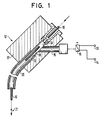
- connection 15 optionally connected to a compressed gas source, namely compressed air source 13 or negative pressure source 14, opens.
- the last-mentioned connection 15 is assigned a changeover valve 16, by means of which the connection 15 can be connected either to the compressed air source 13 or to the vacuum source 14.
- the changeover valve 16 is coupled to the sequence control of the bonder or its bonding head, which is not shown in detail.
- the bond wire guide 12 has a mounting block 17 with a through hole 18, on the coil-side end of which a wire guide nozzle 19 is fixed, while a wire guide tube 20 is inserted at the wedge or capillary end of the through hole 18.
- the connector 15, which can be connected to the compressed air or vacuum source, is located directly behind the wire guide nozzle 19. It opens into the through hole 18 between the wire guide nozzle 19 and the wire guide tube 20.
- the wire guide nozzle 19 is designed similarly to a bond capillary. It has at its wedge or capillary end a nozzle-like constriction through which the bonding wire 10 coming from the wire coil (not shown) is threaded.
- the threading and, if necessary, feeding of the bonding wire 10 to the wedge or to the bond capillary is carried out with compressed air support, in that compressed air is blown into the through-bore 18 through the connection 15 when the valve 16 is switched accordingly.
- the connection 15 opens into the through hole 18 at an acute angle to the longitudinal axis of the wire guide nozzle 19, so that when compressed air is introduced into the through hole 18, the bonding wire 10 through the bond wire guide 12 is pushed fluidically.
- a coaxial flow in the direction of the wedge or the bond capillary forms within the through hole 18 and the wire guide tube 20 around the bond wire 10. This coaxial air flow causes the bonding wire 10 to be pushed forward, depending on the intensity of the air blown in.
- the minimum inside diameter of the constriction of the wire guide nozzle 19 on the outlet side is approximately 100 .mu.m to 130 .mu.m.
- the through hole 18 and the wire guide tube have an inner diameter of approximately 1.5 mm to 2.2 mm. The resulting diameter ratios apply generally.
- connection 15 When the connection 15 is connected to the vacuum source 14, the bonding wire 10 is literally braked while maintaining an essentially constant wire voltage. It is thereby prevented that too much bonding wire is drawn in during loop formation, with the result of a disproportionately large loop.
- larger loops are formed, on the other hand, it is advantageous if compressed air is blown in through the connection 15. As a result, the bond wire 10 is literally pushed in so that there is sufficient wire for loop formation.
- the device described is therefore also particularly suitable when loops of different sizes have to be formed in succession.
- the corresponding control of the fluidic action on the bond wire takes place via the valve 16 in dependence on the bond head control commands.
- the coaxial flow preferably has a swirl component around the bond wire, as a result of which it is literally centered within the through hole 18 and the guide tube 20.
- the guide tube 20 is bent vertically downward toward the “wedge” or toward the bond capillary.
- the device shown and the method described can be retrofitted and used in conventional bonding devices.
- the device described and the method described for gold wire bonding have proven to be particularly advantageous.
- the fluidic action on the bond wire can preferably be made variable, for. B. with regard to pressure and air flow with a corresponding change in the wire tension in adaptation to different process stages of the bondhead.
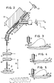
- the construction according to FIG. 2 differs from that according to FIG. 1 by the arrangement of a bond wire slip clamp 23 which either precedes the bond wire guide channel 12, 18, 19, 20 (as shown in FIG. 1 in full) or on the capillary side End of the same, namely at the capillary-side end of the bond wire guide tube 20 (as indicated by dashed lines in FIG. 1), the bond wire slip clamp 23 being either permanently or only effective or closed when the bond head 21 is lowered to the so-called “touch-down” is.
- the bond wire slip clamp 23 is preferably a clamp, the effective clamping surfaces of which are provided with a felt covering or the like, so that the bond wire 10 can still be pulled through when the clamp 23 is closed, but while maintaining a predetermined wire tension and rigidity and with removal a possible twist in the wire. This results in much stiffer loops compared to the prior art that are also free of twist-related distortions. In the loops produced using the described slip clamp 23 there is no danger that they will collapse with the formation of faulty contacts according to FIG. 4. Rather, a loop configuration according to FIG. 5 is obtained. In addition, in the embodiment according to FIG.
- the bond wire guide channel 12, 18, 19, 20, specifically the guide tube 20 is followed by a fixed bond wire clamp 24, that is to say one that cannot be moved with the bond head 21 and which depends on the The height of the bond head 21 or the distance of the capillary tip 26 from the bond point 25 can be closed or opened by withdrawing and correspondingly removing a bond wire section 27 which hangs downward from the capillary tip 26 (see FIG. 3) immediately before the "touch-down" .
- a further bond wire clamp 28 is assigned to the capillary 22, which can be moved up and down with the bond head 21.
- the bonding wire 10 is fed to the capillary 22 using the clamps 24, 28 and the slip clamp 23 as follows:
- the bonding head 21 is lowered from a raised starting or starting position by taking the bonding wire 10 with it by means of the clamp 28 arranged on the bonding head 21, the taking of the bonding wire 10 counter to the action of a coaxial fluid flow in the bonding wire which keeps the bonding wire 10 under low tensile stress. Guide channel and against the action of the slip clamp 23 with previous or simultaneous formation of a "ball" at the free end of the bonding wire 10.
- the bonding wire 10 is both fluidically in the bonding wire Guide channel (connection of the vacuum source 14) and mechanically kept under tension by the bond wire slip clamp 23.
- the bond wire clamp 28 moved with the capillary 22 is opened, so that the "ball” formed at the free end of the bond wire 10 abuts the conical or ball socket-shaped capillary tip 26 while avoiding the described "golf stroke” "arrives. Then the "touch-down” takes place with simultaneous ultrasound excitation of the capillary 22 and formation of a first bond 25.
- the bond head 21 together with the capillary 22 is raised again, to a predetermined loop height, preferably by opening the slip clamp 23, provided that it is a controllable one Slip clamp acts, and if necessary by switching off or switching over the coaxial fluid flow according to the size of the loop to be formed (see above explanations).
- the second bond point 29 is then positioned relative to the capillary 22.
- the bond head 21 together with the capillary 22 is lowered, taking the bond wire 10 with it, again against the effect of the coaxial fluid flow described and, if appropriate, again closed slip clamp 23 until the renewed or second " touch-down "and formation of a second bond 29 under the action of ultrasound.
- the clamp 24 arranged in a fixed manner above the bonding head 21 closes by fixing the bonding wire 10 or correspondingly withdrawing the bonding wire 10 by the capillary 22 moved downward a bond wire section 27 hanging downward from the capillary tip 26 corresponding to FIG. 3 is removed immediately before the second “touch-down”.
- the clamp 24 closes at a predetermined or preprogrammed height of the bonding head 21 or the capillary 22 depending on the material of the bonding wire 10 and the size of the loop.
- the clamp 24 is opened again.
- the bond head 21 is then raised again, namely up to the so-called tail-length height.
- the slip clamp 23 is preferably also opened, provided that it is a controllable slip clamp.
- the coaxial flow described, which retains the bond wire 10 is preferably still effective. This applies in particular when the slip clamp 23 is arranged at the capillary-side end of the bond wire guide tube 20.
- the switching of the coaxial flow ie switching on and switching off and direction, depends on the inherent rigidity, ie the material and diameter of the bonding wire 10.
- the bond wire clamps 24, 28 are conventional wire clamping devices, so that a more detailed illustration and description of the same appears to be unnecessary. The situation is similar with the formation of the capillary 22.
- the slip clamp 23 is a conventional one Wire clip formed, only with the difference that the clamping surfaces are provided with a felt covering or the like. In such a way that the bond wire 10 can still be pulled even when the clamping device is closed.
- the clamping force of the slip clamp 23 is preferably adjustable, in particular variable with adaptation to different bonding wires (material and diameter).
- the device according to FIG. 2 can also be retrofitted or used in conventional bonders.
Abstract
Description
Die Erfindung betrifft eine Vorrichtung sowie ein Verfahren zur gesteuerten Zuführung eines Bonddrahtes, insbesondere Goldbonddrahtes zum "wedge" oder zur Kapillare eines Bondkopfes.The invention relates to a device and a method for the controlled feeding of a bonding wire, in particular gold bonding wire for "wedge" or for the capillary of a bonding head.
Unter Bonden versteht man in der Mikroelektronik im allgemeinen das Verbinden von Bauelementen untereinander durch Kleben oder Schweißen im Unterschied zum üblichen Löten, wo die Verbindung mittels eiens Lotes (meist Zinn-Blei-Legierung) hergestellt wird. Dabei unterscheidet man zwischen Chip-(Die)-Bondverfahren zum Befestigen eines Bauelementes auf einem Trägersubstrat und Draht-Bondverfahren zum Verbinden der Bauelementenanschlüsse mit dem Trägersubstrat mittels feiner Drähte. Bei der Erfindung geht es um ein Detail des letztgenannten Verfahrens. Dabei unterscheidet man das sogenannte Thermokompressionsbonden, auch als nail-head-ball-Bonden bekannt, und das sogenannte Ultraschall-wedge-Bonden. Eine Kombination aus Thermokompressins- und Ultraschall-wedge-Bonden ist das sogenannte Thermosonic-Bonden. Dieses Verfahren erfreut sich immer größerer Beliebtheit. Hier wird meist Golddraht verwendet, der ähnlich wie beim ball-Bonden zu einer Kugel abgeschmolzen wird. Das Verschweißen erfolgt bei mäßiger Hitze mit Hilfe von Ultraschall. Dieses Verfahren ist relativ gut beherrschbar und auch automatisierbar. Zum erwähnten Stand der Technik sei auf die US-A-34 59 355, 33 57 090 und 31 28 649 oder DE-A-33 35 840 und DE-C-35 37 551 verwiesen, die einen gewissen Überblick über die genannte Bondtechnik vermitteln.In microelectronics, bonding is generally understood to mean connecting components to one another by gluing or welding, in contrast to conventional soldering, where the connection is made using a solder (usually a tin-lead alloy). A distinction is made between chip (die) bonding processes for attaching a component to a carrier substrate and wire bonding processes for connecting the component connections to the carrier substrate by means of fine wires. The invention relates to a detail of the latter method. A distinction is made between so-called thermocompression bonding, also known as nail-head-ball bonding, and so-called ultrasonic wedge bonding. A combination of thermocompressine and ultrasonic wedge bonding is the so-called thermosonic bonding. This method is becoming increasingly popular. Gold wire is mostly used here, which is melted into a ball similar to ball bonding. The welding is carried out at moderate heat using ultrasound. This process is relatively easy to control and can also be automated. Regarding the prior art mentioned, reference is made to US-A-34 59 355, 33 57 090 and 31 28 649 or DE-A-33 35 840 and DE-C-35 37 551, which provide a certain overview of the bonding technique mentioned .
Bei allen Draht-Bondverfahren wird der Bonddraht mittels Klemmen oder Zangen entweder zur Bondstelle (pad) nachgezogen oder nach dem Bonden von dieser zum Abreißen des Bonddrahtes wieder weggezogen. Während einer loop-Bildung sind die erwähnten Klemmen und Zangen offen mit der Folge, daß der Bonddraht relativ widerstandslos nachgezogen werden kann. Dies wiederum hat jedoch zur Folge, daß die Länge des nachgezogenen Drahtes und damit die loop-Größe abhängig ist von zufällig herrschenden Widerständen an der Drahtspule und in der Drahtführung. Bei größeren loops hat sich gezeigt, daß die zur loop-Bildung erforderliche Drahtlänge sehr häufig zu klein ist. Bei kleineren loops tritt des öfteren das Gegenteil ein.In all wire bonding processes, the bonding wire is either pulled to the bond point (clamps) by means of clamps or pliers or, after bonding, is pulled away from it again to tear off the bond wire. During a loop formation, the clamps and pliers mentioned are open, with the result that the bond wire can be pulled in relatively without resistance. However, this in turn means that the length of the drawn wire and thus the loop size is dependent of randomly occurring resistances on the wire coil and in the wire guide. With larger loops it has been shown that the wire length required for loop formation is very often too small. The opposite often occurs with smaller loops.
Beim ball-Bonden tritt zusätzlich das Problem des sogenannten "Golfschlages" auf. Der im Abstand von einigen µ von der Kapillaröffnung ausgebildete "ball" widr beim Absenken der Kapillare in Richtung zum "pad" bzw. zur Bondstelle hin gestoßen mit der Folge, daß der "ball" unter praktisch widerstandslosem Nachziehen des Bonddrahtes auf der Bondstelle aufprallt und gegebenenfalls sogar wieder zurückspringt, bevor die Kapillare vollständig abgesenkt ist und den "ball" mit der Bondstelle verschweißt. Dabei verliert der "ball" sehr häufig seine Zentrierung gegenüber der Kapillare bzw. der der Bondstelle zugekehrten etwa konisch erweiterten Kapillaröffnung mit der Folge einer fehlerhaften Bondverbindung. Beim ball-Bonden gilt es also, die Drahtspannung nicht nur während der loop-Bildung, sondern auch beim "touch-down" des "balls" konstant zu halten, um eine präzise Bondverbindung zu erhalten.The problem of the so-called "golf stroke" also occurs with ball bonding. The "ball", formed at a distance of a few microns from the capillary opening, strikes when the capillary is lowered in the direction of the "pad" or towards the bond site, with the result that the "ball" strikes the bond site with virtually no dragging of the bond wire and possibly even jumps back again before the capillary is completely lowered and welds the "ball" to the bond point. The "ball" very often loses its centering with respect to the capillary or the approximately conically widened capillary opening facing the bond site, with the result of an incorrect bond connection. With ball bonding, it is important not only to keep the wire tension constant during the loop formation, but also during the "touch-down" of the "ball" in order to obtain a precise bond connection.
Der vorliegenden Erfindung liegt daher die Aufgabe zugrunde, die Zuführung des Bonddrahtes so zu steuern, daß während des gesamten Betriebs des Bonders eine vorgegebene loop-Größe eingehalten und beim ball-Bonden zusätzlich der sogenannte "Golfschlag" vermieden wird, wobei die mechanische Einwirkung auf den Bonddraht ein Minimum sein soll.The present invention is therefore based on the object of controlling the feeding of the bonding wire in such a way that a predetermined loop size is maintained during the entire operation of the bonder and the so-called "golf stroke" is additionally avoided during ball bonding, the mechanical action on the Bond wire is said to be a minimum.
Zur Lösung dieses Problems wird erfindungsgemäß vorgeschlagen, daß mittels einer koaxialen Gas-, insbesondere Luftströmung, der Bonddraht während des Bondvorganges, insbesondere bei der loop-Bildung, in Richtung zum "wedge" oder zur Kapillare des Bondkopfes geschoben oder auf den Bonddraht ein Zug in Richtung vom "wedge" oder der Kapillare des Bondkopfes weg unter Aufrechterhaltung einer etwa konstanten Drahtspannung ausgeübt wird, wobei zu diesem Zweck dem "wedge" oder der Bondkapillare ein Bonddraht-Führungskanal vorgeordnet ist, in den ein wahlweise mit einer Druckgas-, insbesondere Druckluft- oder Unterdruckquelle verbindbarer Fluidanschluß mündet. Durch die Fluideinwirkung auf den Bonddraht läßt sich dieser je nach Bedarf und gegebenenfalls ohne mechanische Einwirkung schieben oder zurückhalten bzw. bremsen unter Aufrechterhaltung einer im wesentlichen konstanten Drahtspannung, wodurch eine vorgegebene Drahtlänge für die Bildung eines loops relativ genau eingehalten und beim ball-Bonden zusätzlich der sogenannte "Golfschlag" vermieden werden kann. Bei kleineren loops und beim "touch-down" des "balls" wird der Bonddraht in der Regel fluidisch gebremst; bei größeren loops wid der Bonddraht vorzugsweise fluidisch nachgeschoben. Auch das normale Nachziehen des Bonddrahtes vor einem neuen Bondvorgang kann unter Anwendung des genannten Systems rein fluidisch erfolgen. Dann ist eine mechanische Einwirkung auf den Bonddraht nur noch beim Abreißen desselben erforderlich. Dies ist beim dünnen und empfindlichen Golddraht von Vorteil. Es sei an dieser Stelle noch erwähnt, daß es aus der CH-A-592 365 an sich bekannt ist, mittels einer äußeren Gasströmung die Bonddrahtspannung zu steuern. Die Gasströmung wirkt dort jedoch nicht unmittelbar auf den Bonddraht im Sinne eines fluidischen Vorschubs oder einer fluidischen "Abbremsung", sondern nur mittelbar über eine fluidisch drehbewegte Rohrschleife ein, durch die hindurch der Bonddraht zur Bondstelle geführt ist. Eine Beeinflussung der Bonddrahtspannung durch Anschluß einer Unterdruckquelle ist bei der Konstruktion nach der CH-A-592 365 überhaupt nicht vorgesehen.To solve this problem, it is proposed according to the invention that by means of a coaxial gas, in particular air flow, the bond wire is pushed during the bonding process, in particular during the loop formation, in the direction of the "wedge" or to the capillary of the bond head or a train is pulled onto the bond wire Direction is exerted away from the "wedge" or the capillary of the bonding head while maintaining an approximately constant wire tension, for this purpose the "wedge" or the bond capillary is preceded by a bond wire guide channel, into which a fluid connection optionally connected to a compressed gas, in particular compressed air or vacuum source opens. Due to the fluid action on the bond wire, this can be pushed or held back or braked as required and possibly without mechanical action while maintaining a substantially constant wire tension, which means that a predetermined wire length for the formation of a loop is maintained relatively precisely and additionally during ball bonding so-called "golf shot" can be avoided. With smaller loops and with the "touch-down" of the "ball", the bond wire is usually braked fluidically; in the case of larger loops, the bond wire is preferably fluidically fed. The normal drawing of the bonding wire before a new bonding process can also be carried out purely fluidly using the system mentioned. A mechanical action on the bond wire is then only required when the bond wire is torn off. This is an advantage for thin and delicate gold wire. At this point it should also be mentioned that it is known per se from CH-A-592 365 to control the bonding wire voltage by means of an external gas flow. However, the gas flow there does not act directly on the bond wire in the sense of a fluidic feed or a fluidic "deceleration", but only indirectly via a fluidically rotating pipe loop through which the bond wire is guided to the bond site. The construction according to CH-A-592 365 is not intended to influence the bond wire voltage by connecting a vacuum source.
Eine zusätzliche Verbesserung hinsichtlich Präzision und Arbeitsgeschwindigkeit kann durch eine dem Bonddraht-Führungskanal zugeordnete insbesondere vor- oder am kapillarenseitigen Ende derselben angeordnete Bonddraht-Rutschklemme erhalten werden, die entweder permanent oder nur beim Absenken des Bondkopfes zum "touch-down" wirksam bzw. geschlossen ist.An additional improvement in terms of precision and working speed can be obtained by a bond wire slip clamp, which is assigned to the bond wire guide channel and is arranged either in front of or at the end of the capillary, which is either permanently or only effective or closed when the bond head is lowered to "touch-down" .
Vorzugsweise handelt es sich bei der Bonddraht-Rutschklemme um eine Klammer, deren wirksame Klemmflächen filz- oder dgl. -beschichtet sind. Auf diese Weise läßt sich der Bonddraht unter Aufrechterhaltung einer vorgegebenen Spannung durch die Klammer hindurchziehen. Die erfindungsgemäß vorgesehene Bonddraht-Rutschklemme hat neben der Aufrechterhaltung einer vorgegebenen Bonddraht-Spannung und damit Bonddraht-Steifigkeit zusätzlich den großen Vorteil, daß aus dem Bonddraht ein diesem immanenter Drall "herausgenommen bzw. -gezogen" wird mit der Folge, daß sich bei loop-Bildung der Bonddraht nicht mehr unkontrolliert verwerfen kann. Dementsprechend erlaubt die erfindungsgemäß vorgesehene Rutschklemme die Ausbildung exakter loops. Vorzugsweise ist die Rutschklemme steuerbar, d. h. öffen- und schließbar in Abhängigkeit von der Auf- bzw. Abbewegung des Bondkopfes und entsprechender Einwirkung auf den Bonddraht.The bond wire slip clamp is preferably a clamp whose effective clamping surfaces are coated with felt or the like. In this way, the bond wire can be pulled through the clamp while maintaining a predetermined voltage. The bond wire slip clamp provided according to the invention, in addition to maintaining a predetermined bond wire voltage and thus bond wire stiffness, also has the great advantage that an intrinsic twist is "removed or pulled" from the bond wire, with the result that loop- Formation of the bond wire can no longer be discarded uncontrollably. Accordingly, the slip clamp provided according to the invention allows the formation of exact loops. Preferably, the slip clamp is controllable, i. H. can be opened and closed depending on the up and down movement of the bondhead and the corresponding effect on the bond wire.
Die erfindungsgemäß vorgeschlagene Anordnung der Rutschklemme am kapillarenseitigen Ende des Bonddraht-Führungskanals ist aufgrund der Nähe zum Bondkopf besonders wirkungsvoll. Die Ausbildung des Über- oder Unterdrucks im Führungskanal wird durch die Anordnung der Rutschklemme am kapillarenseitigen Ende ds Führungskanals nicht mehr beeinflußt.The arrangement according to the invention of the slip clamp on the capillary-side end of the bond wire guide channel is particularly effective due to the proximity to the bond head. The formation of the overpressure or underpressure in the guide channel is no longer influenced by the arrangement of the slip clamp on the capillary-side end of the guide channel.
Vorzugsweise in Kombination mit der beschriebenen Rutschklemme, aber auch unabhängig davon, ist dem Bonddraht-Führungskanal eine ortsfeste Bonddraht-Klammer nachgeordnet, die in Abhängigkeit von der Höhe des Bondkopfes bzw. vom Abstand der Kapillarenspitze von der Bondstelle schließ- bzw. öffenbar ist unter Rückzug und entsprechender Entfernung eines aus der Kapillarenspitze nach unten heraushängenden Bonddrahtabschnitts unmittelbar vor dem "touch-down".Preferably in combination with the slip clamp described, but also independently of it, a fixed bond wire clamp is arranged downstream of the bond wire guide channel, which can be closed or opened depending on the height of the bond head or the distance of the capillary tip from the bond point, with retraction and corresponding removal of a bond wire section hanging down from the capillary tip immediately before the "touch-down".
Dadurch läßt sich die optimale Drahtlänge für die loop-Bildung vorbestimmen bzw. vorprogrammieren. Überflüssige Drahtlänge wird im Bereich der Kapillarenspitze entfernt, soweit sich dies durch fluidische Abbremsung des Bonddrahts sowie durch Zurückhalten des Bonddrahts mittels der oben beschriebenen Rutschklemme nicht erreichen läßt. Durch diesen Effekt lassen sich nach jeder loop-Bildung Fehlkontakte vermeiden. Vor allem läßt sich erreichen, daß auch beim zweiten Bond nach loop-Bildung der Bonddraht an der Bondstelle über den eigentlichen "Kontaktpunkt" hinaus nicht aufliegt.This allows the optimal wire length for loop formation to be predetermined or preprogrammed. Excess wire length is removed in the area of the capillary tip, as far as this cannot be achieved by fluidic braking of the bonding wire or by restraining the bonding wire using the slip clamp described above. Due to this effect, incorrect contacts can be avoided after each loop formation. Above all, it can be achieved that even in the second bond after loop formation, the bond wire does not rest on the bond point beyond the actual “contact point”.
Unter gleichzeitiger Verwendung der oben beschriebenen Rutschklemme lassen sich also steife loops optimaler Länge unter gleichzeitiger Vermeidung von Fehlkontakten herstellen.With simultaneous use of the slip clamp described above, stiff loops of optimal length can be produced while avoiding faulty contacts.
Unter Verwendung der beschriebenen Konstruktionsmaßnahmen erfolgt das Bonden vorzugsweise entsprechend den in den Ansprüchen 10 bis 12 bzw. 13 und/oder 14 beschriebenen Verfahren.Using the construction measures described, the bonding is preferably carried out in accordance with the methods described in
Nachstehend werden Ausführungsbeispiele des erfindungsgemäßen Systems anhand der beigefügten Zeichnung näher beschrieben. Es zeigen:
- Fig. 1 eine Einfachausführung einer erfindungsgemäß ausgebildeten Vorrichtung in schematischer Seitenansicht, teilweise im Schnitt;
- Fig. 2 eine gegenüber der Ausführungsform gemäß Fig. 1 konstruktiv ergänzte Vorrichtung, ebenfalls in schematischer Seitenansicht und teilweise im Schnitt;
- Fig. 3 die Ausbildung eines loops und die Stellung der Kapillare unmittelbar vor dem zweiten "touch-down";
- Fig. 4 eine fehlerhafte loop-Ausbildung und dementsprechend fehlerhafte Bond-Verbindung, wie sie unter Verwendung herkömmlicher Bonder häufig vorkommen; und
- Fig. 5 die schematische Darstellung eines optimalen loops und einer optimalen Bondverbindung unter Anwendung der erfindungsgemäßen Vorrichtung bzw. des erfindungsgemäßen Verfahrens.
- 1 shows a simple embodiment of a device designed according to the invention in a schematic side view, partly in section;
- FIG. 2 shows a device which is structurally supplemented compared to the embodiment according to FIG. 1, likewise in a schematic side view and partly in section;
- 3 shows the formation of a loop and the position of the capillary immediately before the second “touch-down”;
- 4 shows a faulty loop formation and accordingly faulty bond connection, as frequently occurs using conventional bonders; and
- 5 shows the schematic representation of an optimal loop and an optimal bond connection using the device according to the invention and the method according to the invention.
Gemäß Fig. 1 dient zur gesteuerten Zuführung eines Bonddrahtes 10 zu einem in Fig. 1 nichtdargestellten "wedge" (Keilstück) oder zu einer in Fig. 1 ebenfalls nichtdargestellten Kapillare eines Bondkopfes eine dem "wedge" oder der Bondkapillare vorgeordnete Bonddrahtführung 12, in die ein wahlweise mit einer Druckgas-, nämlich Druckluftquelle 13 oder Unterdruckquelle 14 verbindbarer Anschluß 15 mündet. Dem zuletzt erwähnten Anschluß 15 ist ein Umschaltventil 16 zugeordnet, mittels dem der Anschluß 15 entweder mit der Druckluftquelle 13 oder Unterdruckquelle 14 verbindbar ist. Das Umschaltventil 16 ist mit der Ablaufsteuerung des im einzelnen nichtdargestellten Bonders bzw. dessen Bondkopfes gekoppelt.1 is used for the controlled feeding of a
Die Bonddrahtführung 12 weist einen Montageblock 17 mit einer Durchgangsbohrung 18 auf, an deren spulenseitigem Ende eine Drahtführungsdüse 19 fixiert ist, während am wedge- oder kapillarseitigen Ende der Durchgangsbohrung 18 ein Draht-Leitröhrchen 20 eingesetzt ist. Der mit der Druckluft- oder Unterdruckquelle verbindbare Anschluß 15 liegt unmittelbar hinter der Drahtführungsdüse 19. Er mündet in die Durchgangsbohrung 18 zwischen Drahtführungsdüse 19 und Draht-Leitröhrchen 20. Die Drahtführungsdüse 19 ist ähnlich wie eine Bondkapillare ausgebildet. Sie weist an ihrem wedge- bzw. kapillarseitigen Ende eine düsenartige Verengung auf, durch die der von der nichtdargestellten Drahtspule kommende Bonddraht 10 eingefädelt wird. Die Einfädelung und ggfs. Zuführung des Bonddrahtes 10 zum wedge bzw. zur Bondkapillare erfolgt mit Druckluftunterstützung, indem durch den Anschluß 15 bei entsprechender Schaltung des Ventils 16 Druckluft in die Durchgangsbohrung 18 eingeblasen wird. Der Anschluß 15 mündet in die Durchgangsbohrung 18 in einem spitzen Winkel zur Längsachse der Drahtführungsdüse 19, so daß bei Einleitung von Druckluft in die Durchgangsbohrung 18 der Bonddraht 10 durch die Bond drahtführung 12 hindurch fluidisch geschoben wird. Es bildet sich innerhalb der Durchgangsbohrung 18 und des Draht-Leitröhrchens 20 um den Bonddraht 10 eine koaxiale Strömung in Richtung zum wedge bzw. zur Bondkapillare aus. Diese koaxiale Luftströmung bewirkt ein Nachschieben des Bonddrahtes 10, und zwar in Abhängigkeit von der Intensität der eingeblasenen Luft.The
Bei Verwendung eines Golddrahtes mit einem Durchmesser von etwa 25 µ bis 100 µ beträgt der minimale Innendurchmesser der ausgangsseitigen Verengung der Drahtführungsdüse 19 etwa 100 µ bis 130 µ. Die Durchgangsbohrung 18 sowie das Draht-Leitröhrchen weisen dagegen einen Innendurchmesser von etwa 1,5 mm bis 2,2 mm auf. Die sich daraus ergebenden Durchmesser-Verhältnisse gelten ganz generell.When using a gold wire with a diameter of approximately 25 .mu.m to 100 .mu.m, the minimum inside diameter of the constriction of the
Bei Verbindung des Anschlusses 15 an die Unterdruckquelle 14 wird der Bonddraht 10 regelrecht gebremst unter Aufrechterhaltung einer im wesentlichen konstanten Drahtspannung. Es wird dadurch verhindert, daß insbesondere bei der loop-Bildung zuviel Bonddraht nachgezogen wird mit der Folge eines unverhältnismäßig großen loops. Bei Ausbildung größerer loops ist es dagegen von Vorteil, wenn Druckluft durch den Anschluß 15 eingeblasen wird. Der Bonddraht 10 wird dadurch regelrecht nachgeschoben, so daß ausreichend Draht für die loop-Bildung vorhanden ist. Die beschriebene Vorrichtung eignet sich demnach auch ganz besonders gut, wenn hintereinander loops unterschiedlicher Größe gebildet werden müssen. Die entsprechende Steuerung der fluidischen Einwirkung auf den Bonddraht erfolgt über das Ventil 16 in Abhängigkeit von den Bondkopf-Steuerbefehlen.When the
Beim ball-Bonden wird durch die fluidische Konstanthaltung der Drahtspannung ein sanftes Absenken des "balls" samt Kapillare auf die Bondstelle unter Aufrechterhaltung der ball-Zentrierung erreicht, d. h. der eingangs erläuterte "Golfschlag" vermieden.With ball bonding, the fluidic constant maintenance of the wire tension gently lowers the "ball" together with the capillary onto the bond point while maintaining the ball centering, ie the "golf stroke" explained at the beginning is avoided.
Vorzugsweise weist die koaxiale Strömung eine Drallkomponente um den Bonddraht auf, wodurch dieser innerhalb der Durchgangsbohrung 18 sowie des Leitröhrchens 20 regelrecht zentriert wird. Bei der dargestellten Ausführungsform ist das Leitröhrchen 20 vertikal nach unten zum "wedge" bzw. zur Bondkapillare hin gebogen.The coaxial flow preferably has a swirl component around the bond wire, as a result of which it is literally centered within the through
Die dargestellte Einrichtung sowie das beschriebene Verfahren kann bei herkömmlichen Bondgeräten nachträglich montiert und eingesetzt werden. Als besonders vorteilhaft haben sich die beschriebene Vorrichtung sowie das beschriebene Verfahren beim Golddrahtbonden herausgestellt.The device shown and the method described can be retrofitted and used in conventional bonding devices. The device described and the method described for gold wire bonding have proven to be particularly advantageous.
Die fluidische Einwirkung auf den Bonddraht kann vorzugsweise variierbar gestaltet sein, z. B. hinsichtlich Druck und Luftdurchsatz unter entsprechender Veränderung der Drahtspannung in Anpassung an unterschiedliche Verfahrensstufen des Bondkopfes.The fluidic action on the bond wire can preferably be made variable, for. B. with regard to pressure and air flow with a corresponding change in the wire tension in adaptation to different process stages of the bondhead.
Die Konstruktion nach Fig. 2 unterscheidet sich von derjenigen nach Fig. 1 durch die Anordnung einer Bonddraht-Rutschklemme 23, die dem Bonddraht-Führungskanal 12, 18, 19, 20 entweder vorgeordnet (wie voll ausgezeichnet in Fig. 1 dargestellt) oder am kapillarenseitigen Ende desselben, nämlich am kapillarenseitigen Ende des Bonddraht-Leitröhrchens 20 (wie gestrichelt in Fig. 1 angedeutet) angeordnet ist, wobei die Bonddraht-Rutschklemme 23 entweder permanent oder nur beim Absenken des Bondkopfes 21 zum sogenannten "touch-down" wirksam bzw. geschlossen ist. Die Bonddraht-Rutschklemme 23 ist vorzugsweise eine Klammer, deren wirksame Klemmflächen mit einem Filzbelag oder dgl. versehen sind, so daß der Bonddraht 10 auch bei geschlossener Klammer 23 durch diese noch hindurchziehbar ist, jedoch unter Aufrechterhaltung einer vorbestimmten Drahtspannung und -steifigkeit sowie unter Herausnahme eines etwaigen Dralls im Draht. Dadurch werden im Vergleich zum Stand der Technik wesentlich steifere loops erhalten, die darüber hinaus frei von drallbedingten Verwerfungen sind. Bei den unter Verwendung der beschriebenen Rutschklemme 23 hergestellten loops besteht nicht die Gefahr, daß diese unter Ausbildung von Fehlkontakten entsprechend Fig. 4 in sich zusammenfallen. Vielmehr wird eine loop-Konfiguration entsprechend Fig. 5 erhalten. Darüber hinaus ist bei der Ausführungsform nach Fig. 2 dem Bonddraht-Führungskanal 12, 18, 19, 20, und zwar konkret dem Leitröhrchen 20, eine ortsfeste, d. h. nicht mit dem Bondkopf 21 mitbewegbare Bonddraht-Klammer 24 nachgeordnet, die in Abhängigkeit von der Höhe des Bondkopfes 21 bzw. vom Abstand der Kapillarenspitze 26 von der Bondstelle 25 schließ- bzw. öffenbar ist unter Rückzug und entsprechender Entfernung eines aus der Kapillarenspitze 26 nach unten heraushängenden Bonddrahtabschnitts 27 (siehe Fig. 3) unmittelbar vor dem "touch-down".The construction according to FIG. 2 differs from that according to FIG. 1 by the arrangement of a bond
Der Kapillare 22 ist eine weitere Bonddraht-Klammer 28 zugeordnet, wobei diese mit dem Bondkopf 21 auf- und abbewegbar ist.A further
Die Zuführung des Bonddrahtes 10 zur Kapillare 22 erfolgt unter Verwendung der Klammern 24, 28 sowie der Rutschklemme 23 wie folgt:The
Zunächst wird der Bondkopf 21 von einer angehobenen Start- bzw. Ausgangsposition unter Mitnahme des Bonddrahtes 10 mittels der am Bondkopf 21 angeordneten Klammer 28 abgesenkt, wobei die Mitnahme des Bonddrahtes 10 entgegen der Wirkung einer den Bonddraht 10 unter geringer Zugspannung haltenden koaxialen Fluidströmung im Bonddraht-Führungskanal und entgegen der Wirkung der Rutschklemme 23 bei vorheriger oder gleichzeitiger Ausbildung eines "balls" am freien Ende des Bondrahtes 10 erfolgt. Der Bonddraht 10 wird also bei dieser Absenkbewegung des Bondkopfes 21 bzw. der diesem zugeordneten Bondkapillare 22 sowohl fluidisch im Bonddraht- Führungskanal (Anschluß der Unterdruckquelle 14) als auch mechanisch durch die Bonddraht-Rutschklemme 23 unter Spannung gehalten.First, the
Kurz vor dem "touch-down" wird die mit der Kapillare 22 mitbewegte Bonddraht-Klammer 28 geöffnet, so daß der am freien Ende des Bonddrahtes 10 ausgebildete "ball" in Anlage an die konisch oder kugelpfannenartig ausgebildete Kapillarenspitze 26 unter Vermeidung des beschriebenen "Golfschlages" gelangt. Dann erfolgt der "touch-down" unter gleichzeitiger Ultraschallerregung der Kapillare 22 und Ausbildung eines ersten Bonds 25.Shortly before the "touch-down", the
Nachdem der erste Bond 25 auf einem "pad 31" ausgebildet worden ist, wird der Bondkopf 21 samt Kapillare 22 wieder hochgefahren, und zwar bis zu einer vorgegebenen loop-Höhe, und zwar vorzugsweise unter Öffnung der Rutschklemme 23, sofern es sich um eine steuerbare Rutschklemme handelt, und gegebenenfalls unter Ab- oder Umschaltung der koaxialen Fluidströmung entsprechend der Größe des auszubildenden loops (siehe obige Ausführungen dazu). Anschließend erfolgt die Positionierung der zweiten Bondstelle 29 gegenüber der Kapillare 22. Der Bondkopf 21 samt Kapillare 22 wird abgesenkt unter Mitnahme des Bonddrahtes 10, und zwar wieder entgegen der Wirkung der beschriebenen koaxialen Fluidströmung sowie gegebenenfalls erneut geschlossenen Rutschklemme 23 bis zum erneuten bzw. zweiten "touch-down" und Ausbildung ei s zweiten Bonds 29 unter Einwirkung von Ultraschall. Vorzugsweise schließt kurz vor dem zweiten "touch-down" ausgehend von der loop-Höhe die oberhalb des Bondkopfes 21 ortsfest angeordnete Klammer 24 unter Fixierung des Bonddrahtes 10 bzw. entsprechendem Rückzug des Bonddrahtes 10 durch die nach unten bewegte Kapillare 22. Auf diese Weise wird ein aus der Kapillarenspitze 26 nach unten heraushängender Bonddrahtabschnitt 27 entsprechend Fig. 3 unmittelbar vor dem zweiten "touch-down" entfernt. Dadurch erhält man entsprechend Fig. 5 einen zweiten Bond 29, ohne daß der Bonddraht über den eigentlichen "Kontaktpunkt" hinaus auf dem Substrat aufliegt bzw. dieses berührt. Wird die überschüssige Bonddrahtlänge 27 nicht wie beschrieben entfernt, besteht die Gefahr, daß ein zweiter Bond 29 entsprechend Fig. 4 entsteht, bei dem der Draht über eine unverhältnismäßig große Länge auf dem Substrat aufliegt. Die Klammer 24 schließt bei vorbestimmter bzw. vorprogrammierter Höhe des Bondkopfes 21 bzw. der Kapillare 22 abhängig von dem Material des Bonddrahtes 10 sowie der Größe des loops. Nach Ausbildung des zweiten Bonds 29 wird die Klammer 24 wieder geöffnet. Des weiteren wird der Bondkopf 21 dann wieder hochgefahren, und zwar bis zur sogenannten tail-length-Höhe. In diesem Fall ist vorzugsweise auch die Rutschklemme 23 geöffnet, sofern es sich um eien steuerbare Rutschklemme handelt. Doch nach wie vor ist vorzugsweise die beschriebene Koaxialströmung wirksam, die den Bonddraht 10 zurückhält. Diese gilt insbesondere dann, wenn die Rutschklemme 23 am kapillarenseitigen Ende des Bonddraht-Leitröhrchens 20 angeordnet ist. Letztlich hängt die Schaltung der Koaxialströmung, d. h. Ein- und Abschaltung sowie Richtung von der Eigensteifigkeit, d. h. Material und Durchmesser des Bonddrahts 10, ab.After the
In tail-length-Höhe des Bondkopfes 21 wird die dem Bondkopf zugeordnete Klammer 28 wieder geschlossen. Dann fährt der Bondkopf 21 zurück zur Ausgangsposition unter Abreißen des Bonddrahtes 10. Ein erneuter Bondvorgang in der beschriebenen Weise kann beginnen.At the tail-length height of the
Bei den Bonddraht-Klammern 24, 28 handelt es sich um herkömmliche Draht-Klemmeinrichtungen, so daß eine nähere Darstellung und Beschreibung derselben entbehrlich erscheint. Ähnlich verhält es sich bei der Ausbildung der Kapillare 22.The bond wire clamps 24, 28 are conventional wire clamping devices, so that a more detailed illustration and description of the same appears to be unnecessary. The situation is similar with the formation of the capillary 22.
Die Rutschklemme 23 ist entsprechend einer herkömmlichen Drahtklammer ausgebildet, nur mit dem Unterschied, daß die Klemmflächen mit einem Filzbelag oder dgl. versehen sind derart, daß auch bei geschlossener Klemmeinrichtung der Bonddraht 10 noch hindurchgezogen werden kann. Vorzugsweise ist die Klemmkraft der Rutschklemme 23 einstellbar, insbesondere variierbar unter Anpassung an verschiedene Bonddrähte (Material und Durchmesser).The
Auch die Vorrichtung gemäß Fig. 2 kann bei herkömmlichen Bondern nachträglich montiert bzw. eingesetzt werden.The device according to FIG. 2 can also be retrofitted or used in conventional bonders.
Sämtliche in den Anmeldungsunterlagen offenbarten Merkmale werden als erfindungswesentlich beansprucht, soweit sie einzeln oder in Kombination gegenüber dem Stand der Technik neu sind.All features disclosed in the application documents are claimed as essential to the invention, insofar as they are new compared to the prior art, individually or in combination.
Claims (14)
gekennzeichnet durch
einen dem "wedge" oder der Bondkapillare (22) vorgeordneten Bonddraht-Führungskanal (12, 18, 19, 20), in den ein wahlweise mit einer Druckgas-, insbesondere Druckluft (13)- oder Unterdruckquelle (14) verbindbarer Fluidanschluß (15) mündet.1. Device for the controlled feeding of a bonding wire, in particular gold bonding wire (10), for "wedge" (wedge piece) or for the capillary (22) of an up and down (double arrow 30) bonding head (21),
marked by
a bond wire guide channel (12, 18, 19, 20) arranged upstream of the "wedge" or the bond capillary (22), into which a fluid connection (15) optionally connectable to a compressed gas, in particular compressed air (13) or vacuum source (14) flows.
dadurch gekennzeichnet, daß dem Fluidanschluß (15) ein mit der Bondkopfsteuerung gekoppeltes Umschaltventil (16) zugeordnet ist, mittels dem der Anschluß (15) entweder mit der Druckgas- bzw. Druckluftquelle (13) oder Unterdruckquelle (14) verbindbar ist.2. Device according to claim 1,
characterized in that the fluid connection (15) is associated with a changeover valve (16) coupled to the bondhead control, by means of which the connection (15) can be connected either to the compressed gas or compressed air source (13) or to the vacuum source (14).
dadurch gekennzeichnet, daß der Bonddraht-Führungskanal eine Drahtführungsdüse (19) aufweist, an die sich wedge- oder kapillarseitig ein Draht-Leitröhrchen (20) größeren Innendurchmessers anschließt, wobei der mit der Druckgas- bzw. Druckluftquelle (13) oder Unterdruckquelle (14) verbindbare Fluidanschluß (15) unmittelbar hinter der Drahtführungsdüse (19) liegt.3. Device according to claim 1 or 2,
characterized in that the bond wire guide channel has a wire guide nozzle (19), to which a wire guide tube (20) of larger internal diameter connects on the wedge or capillary side, the one with the compressed gas or compressed air source (13) or vacuum source (14) connectable fluid connection (15) is immediately behind the wire guide nozzle (19).
dadurch gekennzeichnet, daß die Drahtführungsdüse (19) am spulenseitigen Ende einer in einem Montageblock (17) ausgebildeten Durchgangsbohrung (18) fixiert ist, während das Draht-Leitröhrchen (20) am wedge- oder kapillarseitigen Ende der Durchgangsbohrung (18) angeschlossen ist, und daß der mit der Druckgas- bzw. Druckluft- oder Unterdruckquelle verbindbare Fluidanschluß (15) zwischen Drahtführungsdüse (19) und Draht-Leitröhrchen (20) in die Durchgangsbohrung (18) mündet.4. The device according to claim 3,
characterized in that the wire guide nozzle (19) is fixed to the coil-side end of a through hole (18) formed in a mounting block (17), while the wire guide tube (20) is connected to the wedge or capillary end of the through hole (18), and that the fluid connection (15) connectable to the compressed gas or compressed air or vacuum source between the wire guide nozzle (19) and the wire guide tube (20) opens into the through hole (18).
dadurch gekennzeichnet, daß der mit der Druckgas- bzw. Druckluft- oder Unterdruckquelle verbindbare Fluidanschluß (15) unter einem spitzen Winkel zur Drahtführungsdüse (19) in die Bonddrahtführung (12) mündet.5. Device according to one of claims 1 to 4,
characterized in that the fluid connection (15) which can be connected to the compressed gas or compressed air or vacuum source opens into the bond wire guide (12) at an acute angle to the wire guide nozzle (19).
dadurch gekennzeichnet, daß der Innendurchmesser der ausgangsseitig angeordneten Verengung der Drahtführungsdüse (19) bei einem Drahtdurchmesser von kleiner als 100 µ etwa 100 bis 130 µ beträgt, während das der Drahtführungsdüse (19) folgende Draht-Leitröhrchen (20) einen Innendurchmesser von etwa 1,5 bis 2,2 mm aufweist.6. Device according to one of claims 3 to 5,
characterized in that the inside diameter of the constriction of the wire guide nozzle (19) arranged on the outlet side with a wire diameter of less than 100 µ is about 100 to 130 µ, while the wire guide tube (20) following the wire guide nozzle (19) has an inside diameter of about 1, 5 to 2.2 mm.
gekennzeichnet durch eine den Bonddraht-Führungskanal (12, 18, 19, 20) zugeordnete, insbesondere vor- oder am kappilarenseitigen Ende desselben angeordnete Bonddraht-Rutschklemme (23), die entweder permanent oder nur beim Absenken des Bondkopfes (21) zum "touch-down" wirksam bzw. geschlossen ist.7. The device according to one or more of claims 1 to 6,
characterized by a bond wire slip clamp (23) assigned to the bond wire guiding channel (12, 18, 19, 20), in particular arranged in front of or at the end of the capillary, which either permanently or only when the bond head (21) is lowered to "touch" down "is effective or closed.
dadurch gekennzeichnet, daß die Bonddraht-Rutschklemme (23) durch eine Klammer gebildet ist, deren wirksame Klemmflächen filz- oder dgl. -beschichtet sind.8. The device according to claim 7,
characterized in that the bond wire slip clamp (23) is formed by a clamp, the effective clamping surfaces of which are coated with felt or the like.
dadurch gekennzeichnet, daß dem Bonddraht-Führungskanal (12, 18, 19, 20) eine ortsfeste Bonddraht-Klammer (24) nachgeordnet ist, die nach Absenken des Bondkopfes (21) von einer vorgegebenen loop-Höhe auf eine vorprogrammierbare Zwischenhöhe schließbar ist unter Rückzug und entsprechender Entfernung eiens aus der Kapillarenspitze (26) nach unten heraushängenden Bonddrahtabschnitts (27) unmittelbar vor dem nachfolgenden "touch-down".9. The device, in particular according to one of claims 1 to 8,
characterized in that the bond wire guide channel (12, 18, 19, 20) is followed by a fixed bond wire clamp (24) which, after the bond head (21) has been lowered, can be closed from a predetermined loop height to a pre-programmable intermediate height with retreat and corresponding removal of a bond wire section (27) hanging down from the capillary tip (26) immediately before the subsequent “touch-down”.
dadurch gekennzeichnet, daß mittels einer koaxialen Gas-, insbesondere Luftströmung, der Bonddraht (10) während des Bondvorganges, insbesondere bei der loop-Bildung, in Richtung zum "wedge" oder zur Kapillare (22) des Bondkopfes (21) geschoben oder auf den Bonddraht (10) ein Zug in Richtung vom (wedge) oder der Kapillare (22) des Bondkopfes (21) weg unter Aufrechterhaltung einer etwa konstanten Drahtspannung ausgeübt wird.10. Method for the controlled feeding of a bonding wire, in particular gold bonding wire (10) to the "wedge" (wedge piece) or to the capillary (22) of an up and down (double arrow 30) bonding head (21),
characterized in that by means of a coaxial gas, in particular air flow, the bonding wire (10) during the bonding process, in particular during the loop formation, is pushed in the direction of the "wedge" or to the capillary (22) of the bonding head (21) or onto the Bonding wire (10) a pull in the direction from (wedge) or the capillary (22) of the bonding head (21) away while maintaining an approximately constant wire tension is exerted.
dadurch gekennzeichnet, daß die Richtung der koaxialen Gas-, insbesondere Luftströmung, während des Bondvorganges umkehrbar sowie die Intensität (Druck- und/oder Durchsatz) der Gas-, insbesondere Luftströmung, variierbar ist.11. The method according to claim 10,
characterized in that the direction of the coaxial gas, in particular air flow, is reversible during the bonding process and the intensity (pressure and / or throughput) of the gas, in particular air flow, can be varied.
dadurch gekennzeichnet, daß die koaxiale Gas- bzw. Luftströmung eine Drallkomponente um den Bonddraht (10) herum aufweist.12. The method according to claim 10 or 11,
characterized in that the coaxial gas or air flow has a swirl component around the bond wire (10).
gekennzeichnet durch folgende Verfahrensschritte:
characterized by the following process steps:
dadurch gekennzeichnet, daß kurz vor dem jeweils zweiten "touch-down" ausgehend von der loop-Höhe eine oberhalb des Bondkopfes (21) ortsfest angeordnete Klammer (24) schließt unter Fixierung des Bonddrahtes (10) bzw. entsprechenden Rückzug des Bonddrahtes (10) durch die nach unten bewegte Kapillare (22), wobei die ortsfest angeordnete Klammer (24) bei vorprogrammierter Zwischenhöhe des Bondkopfes (21) bzw. der Kapillare (22) schließt, um nach Ausbildung des jeweils zweiten Bonds (29) wieder geöffnet zu werden.14. The method, in particular according to claim 13,
characterized in that shortly before the respective second "touch-down", starting from the loop height, a clamp (24) which is arranged in a fixed manner above the bond head (21) closes with fixation of the bond wire (10) or corresponding withdrawal of the bond wire (10) through the downwardly moving capillary (22), the stationary clamp (24) closing at a preprogrammed intermediate height of the bonding head (21) or the capillary (22) in order to be opened again after the second bond (29) has been formed.
Applications Claiming Priority (4)
| Application Number | Priority Date | Filing Date | Title |
|---|---|---|---|
| DE3805584A DE3805584A1 (en) | 1988-02-23 | 1988-02-23 | Device and method for the controlled feeding of a bonding wire to the wedge or to the capillary of a bonding head |
| DE3805584 | 1988-02-23 | ||
| DE3825373A DE3825373A1 (en) | 1988-07-26 | 1988-07-26 | Device and method for controlled supply of a bonding wire to the wedge or to the capillary of a bonding head |
| DE3825373 | 1988-07-26 |
Publications (3)
| Publication Number | Publication Date |
|---|---|
| EP0330053A2 true EP0330053A2 (en) | 1989-08-30 |
| EP0330053A3 EP0330053A3 (en) | 1990-03-21 |
| EP0330053B1 EP0330053B1 (en) | 1994-08-03 |
Family
ID=25865111
Family Applications (1)
| Application Number | Title | Priority Date | Filing Date |
|---|---|---|---|
| EP19890102516 Expired - Lifetime EP0330053B1 (en) | 1988-02-23 | 1989-02-14 | Device and method for the controlled supply of a bonding wire to the wedge or to the capillary of a bonding head |
Country Status (6)
| Country | Link |
|---|---|
| US (1) | US4928871A (en) |
| EP (1) | EP0330053B1 (en) |
| JP (1) | JPH01302736A (en) |
| KR (1) | KR900002673A (en) |
| AT (1) | ATE109387T1 (en) |
| DE (1) | DE58908123D1 (en) |
Cited By (2)
| Publication number | Priority date | Publication date | Assignee | Title |
|---|---|---|---|---|
| WO1999015452A1 (en) * | 1997-09-20 | 1999-04-01 | Hesse & Knipps Gmbh | Wire brake |
| CN106001577A (en) * | 2016-06-27 | 2016-10-12 | 西安智熔金属打印系统有限公司 | Wire feeding mechanism, wire feeding device and additive manufacturing equipment based on additive manufacturing technology |
Families Citing this family (17)
| Publication number | Priority date | Publication date | Assignee | Title |
|---|---|---|---|---|
| JP2559539B2 (en) * | 1991-03-13 | 1996-12-04 | ローム株式会社 | Bonding device |
| US20070228110A1 (en) * | 1993-11-16 | 2007-10-04 | Formfactor, Inc. | Method Of Wirebonding That Utilizes A Gas Flow Within A Capillary From Which A Wire Is Played Out |
| JP3075100B2 (en) * | 1994-10-06 | 2000-08-07 | 松下電器産業株式会社 | Wire bonding apparatus and wire bonding method |
| JPH0945721A (en) * | 1995-08-03 | 1997-02-14 | Kaijo Corp | Device and method for guiding wire and wire bonding apparatus having this device |
| DE19617470B4 (en) * | 1995-11-07 | 2006-02-02 | Hesse & Knipps Gmbh | thread feed |
| JP3741184B2 (en) * | 1998-07-27 | 2006-02-01 | 日本テキサス・インスツルメンツ株式会社 | Semiconductor device |
| JP2000082717A (en) * | 1998-09-07 | 2000-03-21 | Shinkawa Ltd | Wire bonding method |
| AU720299B3 (en) * | 2000-03-09 | 2000-05-25 | Edmunds Gumbelis | Feeding machanism for welding wire |
| JP2002064117A (en) * | 2000-08-22 | 2002-02-28 | Mitsubishi Electric Corp | Wire bonding method and apparatus, and semiconductor device |
| JP2002083837A (en) * | 2000-09-07 | 2002-03-22 | Shinkawa Ltd | Wire bonding apparatus |
| JP2002151545A (en) * | 2000-11-10 | 2002-05-24 | Nec Corp | Wire bonder |
| US6641025B2 (en) * | 2001-08-30 | 2003-11-04 | Micron Technology, Inc. | Threading tool and method for bond wire capillary tubes |
| US7311239B2 (en) * | 2004-05-04 | 2007-12-25 | Sv Probe Pte Ltd. | Probe attach tool |
| US7954689B2 (en) * | 2007-05-04 | 2011-06-07 | Asm Technology Singapore Pte Ltd | Vacuum wire tensioner for wire bonder |
| US8459530B2 (en) * | 2009-10-29 | 2013-06-11 | Asm Technology Singapore Pte Ltd | Automatic wire feeding method for wire bonders |
| TWI566875B (en) * | 2014-02-24 | 2017-01-21 | 新川股份有限公司 | Wire tensioner |
| DE102020117641A1 (en) * | 2020-07-03 | 2022-01-05 | Hesse Gmbh | Wire guide module and ultrasonic wire bonder herewith |
Citations (1)
| Publication number | Priority date | Publication date | Assignee | Title |
|---|---|---|---|---|
| US3116889A (en) * | 1961-05-25 | 1964-01-07 | Electroglas Inc | Threading device with magazine and method |
Family Cites Families (4)
| Publication number | Priority date | Publication date | Assignee | Title |
|---|---|---|---|---|
| US3357090A (en) * | 1963-05-23 | 1967-12-12 | Transitron Electronic Corp | Vibratory welding tip and method of welding |
| CH592365A5 (en) * | 1975-12-23 | 1977-10-31 | Esec Sales Sa | |
| JPS58218131A (en) * | 1982-06-14 | 1983-12-19 | Mitsubishi Electric Corp | Feeder for wire of nail head wire bonder |
| JPS61159743A (en) * | 1985-01-07 | 1986-07-19 | Toshiba Corp | Method and apparatus for wire-bonding of semiconductor device |
-
1989
- 1989-02-14 AT AT89102516T patent/ATE109387T1/en active
- 1989-02-14 EP EP19890102516 patent/EP0330053B1/en not_active Expired - Lifetime
- 1989-02-14 DE DE58908123T patent/DE58908123D1/en not_active Expired - Lifetime
- 1989-02-22 US US07/314,191 patent/US4928871A/en not_active Expired - Lifetime
- 1989-02-22 KR KR1019890002112A patent/KR900002673A/en not_active Application Discontinuation
- 1989-02-23 JP JP1045046A patent/JPH01302736A/en active Pending
Patent Citations (1)
| Publication number | Priority date | Publication date | Assignee | Title |
|---|---|---|---|---|
| US3116889A (en) * | 1961-05-25 | 1964-01-07 | Electroglas Inc | Threading device with magazine and method |
Non-Patent Citations (2)
| Title |
|---|
| PATENT ABSTRACTS OF JAPAN vol. 6, no. 6 (E-89)(884) 14 Januar 1982, & JP-A-56 129333 (HITACHI SEISAKUSHO K.K.) 09 Oktober 1981, * |
| SCHWEIZERISCHE TECHNISCHE ZEITSCHRIFT no. 3, 20 Januar 1972, Wabern (CH) Seiten 35 - 36; Walter Wulch: "Thermo-Kompressionsschweissen von Anschlussdr{hten in der Mikrotechnik" * |
Cited By (3)
| Publication number | Priority date | Publication date | Assignee | Title |
|---|---|---|---|---|
| WO1999015452A1 (en) * | 1997-09-20 | 1999-04-01 | Hesse & Knipps Gmbh | Wire brake |
| CN106001577A (en) * | 2016-06-27 | 2016-10-12 | 西安智熔金属打印系统有限公司 | Wire feeding mechanism, wire feeding device and additive manufacturing equipment based on additive manufacturing technology |
| CN106001577B (en) * | 2016-06-27 | 2018-06-22 | 西安智熔金属打印系统有限公司 | Wire feeder, wire feeder and increasing material manufacturing equipment based on increases material manufacturing technology |
Also Published As
| Publication number | Publication date |
|---|---|
| DE58908123D1 (en) | 1994-09-08 |
| ATE109387T1 (en) | 1994-08-15 |
| JPH01302736A (en) | 1989-12-06 |
| US4928871A (en) | 1990-05-29 |
| EP0330053A3 (en) | 1990-03-21 |
| EP0330053B1 (en) | 1994-08-03 |
| KR900002673A (en) | 1990-02-28 |
Similar Documents
| Publication | Publication Date | Title |
|---|---|---|
| EP0330053B1 (en) | Device and method for the controlled supply of a bonding wire to the wedge or to the capillary of a bonding head | |
| EP0266843B1 (en) | Device for depositing amounts of droplet-shaped solder on surfaces to be wetted | |
| EP1778901B1 (en) | Spindle having an injector channel and method for piecing up the yarn end in an air jet spinning machine | |
| DE19732236A1 (en) | Capillary tube for wire bonding apparatus | |
| DE3810929C2 (en) | ||
| EP0206041A2 (en) | Method for the automatic and repetitive threading of the wire electrode of a wire-cutting discharge machine, and device for carrying out the method | |
| DE3240200A1 (en) | SPLITTING DEVICE FOR A WIDNED THREAD | |
| DE3411577A1 (en) | METHOD AND DEVICE FOR APPLYING A YARN IN A FIBER BUNCH YARN SPINNING UNIT | |
| WO2003068445A1 (en) | Arrangement for wire bonding and method for producing a bonding connection | |
| DE3504422C2 (en) | ||
| DE3805584A1 (en) | Device and method for the controlled feeding of a bonding wire to the wedge or to the capillary of a bonding head | |
| DE3342858C2 (en) | ||
| EP0796936A2 (en) | Method and device to pneumatically assist the insertion and the tensioning of a weft thread on looms | |
| CH675035A5 (en) | ||
| DE3825373A1 (en) | Device and method for controlled supply of a bonding wire to the wedge or to the capillary of a bonding head | |
| DE3305479A1 (en) | METHOD AND DEVICE FOR PNEUMATIC SPLICING OF SPONNED THREADS | |
| EP0649701A1 (en) | Device and method of wire-bonding | |
| DE4326478C2 (en) | Bonding head for ultrasonic bonding | |
| EP1155181B1 (en) | Sewing machine with a thread withdrawing device | |
| DE3541220C1 (en) | Method and device for re-spinning a spinning device | |
| DE102007013100A1 (en) | Method for producing a wedge-wedge wire bridge | |
| DE3048440A1 (en) | DEVICE FOR INSERTING A WIFE | |
| EP0945208B1 (en) | Apparatus and method for ball bonding | |
| DE4404555C1 (en) | Threading of yarns at two for one twister | |
| EP1175274B1 (en) | Wire erosion device |
Legal Events
| Date | Code | Title | Description |
|---|---|---|---|
| PUAI | Public reference made under article 153(3) epc to a published international application that has entered the european phase |
Free format text: ORIGINAL CODE: 0009012 |
|
| AK | Designated contracting states |
Kind code of ref document: A2 Designated state(s): AT BE CH DE ES FR GB GR IT LI LU NL SE |
|
| PUAL | Search report despatched |
Free format text: ORIGINAL CODE: 0009013 |
|
| AK | Designated contracting states |
Kind code of ref document: A3 Designated state(s): AT BE CH DE ES FR GB GR IT LI LU NL SE |
|
| 17P | Request for examination filed |
Effective date: 19900921 |
|
| 17Q | First examination report despatched |
Effective date: 19911212 |
|
| RAP1 | Party data changed (applicant data changed or rights of an application transferred) |
Owner name: F & K DELVOTEC BONDTECHNIK GMBH |
|
| GRAA | (expected) grant |
Free format text: ORIGINAL CODE: 0009210 |
|
| AK | Designated contracting states |
Kind code of ref document: B1 Designated state(s): AT BE CH DE ES FR GB GR IT LI LU NL SE |
|
| PG25 | Lapsed in a contracting state [announced via postgrant information from national office to epo] |
Ref country code: IT Free format text: LAPSE BECAUSE OF FAILURE TO SUBMIT A TRANSLATION OF THE DESCRIPTION OR TO PAY THE FEE WITHIN THE PRE;WARNING: LAPSES OF ITALIAN PATENTS WITH EFFECTIVE DATE BEFORE 2007 MAY HAVE OCCURRED AT ANY TIME BEFORE 2007. THE CORRECT EFFECTIVE DATE MAY BE DIFFERENT FROM THE ONE RECORDED.SCRIBED TIME-LIMIT Effective date: 19940803 Ref country code: GR Free format text: LAPSE BECAUSE OF FAILURE TO SUBMIT A TRANSLATION OF THE DESCRIPTION OR TO PAY THE FEE WITHIN THE PRESCRIBED TIME-LIMIT Effective date: 19940803 Ref country code: NL Effective date: 19940803 Ref country code: BE Effective date: 19940803 Ref country code: FR Effective date: 19940803 Ref country code: ES Free format text: THE PATENT HAS BEEN ANNULLED BY A DECISION OF A NATIONAL AUTHORITY Effective date: 19940803 |
|
| REF | Corresponds to: |
Ref document number: 109387 Country of ref document: AT Date of ref document: 19940815 Kind code of ref document: T |
|
| REF | Corresponds to: |
Ref document number: 58908123 Country of ref document: DE Date of ref document: 19940908 |
|
| GBT | Gb: translation of ep patent filed (gb section 77(6)(a)/1977) |
Effective date: 19940822 |
|
| PG25 | Lapsed in a contracting state [announced via postgrant information from national office to epo] |
Ref country code: SE Effective date: 19941103 |
|
| EN | Fr: translation not filed | ||
| NLV1 | Nl: lapsed or annulled due to failure to fulfill the requirements of art. 29p and 29m of the patents act | ||
| PG25 | Lapsed in a contracting state [announced via postgrant information from national office to epo] |
Ref country code: AT Effective date: 19950214 Ref country code: GB Effective date: 19950214 |
|
| PG25 | Lapsed in a contracting state [announced via postgrant information from national office to epo] |
Ref country code: CH Effective date: 19950228 Ref country code: LI Effective date: 19950228 Ref country code: LU Free format text: LAPSE BECAUSE OF NON-PAYMENT OF DUE FEES Effective date: 19950228 |
|
| PLBE | No opposition filed within time limit |
Free format text: ORIGINAL CODE: 0009261 |
|
| STAA | Information on the status of an ep patent application or granted ep patent |
Free format text: STATUS: NO OPPOSITION FILED WITHIN TIME LIMIT |
|
| 26N | No opposition filed | ||
| GBPC | Gb: european patent ceased through non-payment of renewal fee |
Effective date: 19950214 |
|
| PGFP | Annual fee paid to national office [announced via postgrant information from national office to epo] |
Ref country code: DE Payment date: 20080429 Year of fee payment: 20 |