EP0341760A2 - Honeycomb blind constructions and method of assembling honeycomb blind constructions - Google Patents
Honeycomb blind constructions and method of assembling honeycomb blind constructions Download PDFInfo
- Publication number
- EP0341760A2 EP0341760A2 EP89113014A EP89113014A EP0341760A2 EP 0341760 A2 EP0341760 A2 EP 0341760A2 EP 89113014 A EP89113014 A EP 89113014A EP 89113014 A EP89113014 A EP 89113014A EP 0341760 A2 EP0341760 A2 EP 0341760A2
- Authority
- EP
- European Patent Office
- Prior art keywords
- panel
- channel
- strip
- honeycomb
- side track
- Prior art date
- Legal status (The legal status is an assumption and is not a legal conclusion. Google has not performed a legal analysis and makes no representation as to the accuracy of the status listed.)
- Granted
Links
Images


Classifications
-
- E—FIXED CONSTRUCTIONS
- E06—DOORS, WINDOWS, SHUTTERS, OR ROLLER BLINDS IN GENERAL; LADDERS
- E06B—FIXED OR MOVABLE CLOSURES FOR OPENINGS IN BUILDINGS, VEHICLES, FENCES OR LIKE ENCLOSURES IN GENERAL, e.g. DOORS, WINDOWS, BLINDS, GATES
- E06B9/00—Screening or protective devices for wall or similar openings, with or without operating or securing mechanisms; Closures of similar construction
- E06B9/24—Screens or other constructions affording protection against light, especially against sunshine; Similar screens for privacy or appearance; Slat blinds
- E06B9/26—Lamellar or like blinds, e.g. venetian blinds
- E06B9/28—Lamellar or like blinds, e.g. venetian blinds with horizontal lamellae, e.g. non-liftable
- E06B9/30—Lamellar or like blinds, e.g. venetian blinds with horizontal lamellae, e.g. non-liftable liftable
- E06B9/32—Operating, guiding, or securing devices therefor
- E06B9/327—Guides for raisable lamellar blinds with horizontal lamellae
-
- E—FIXED CONSTRUCTIONS
- E06—DOORS, WINDOWS, SHUTTERS, OR ROLLER BLINDS IN GENERAL; LADDERS
- E06B—FIXED OR MOVABLE CLOSURES FOR OPENINGS IN BUILDINGS, VEHICLES, FENCES OR LIKE ENCLOSURES IN GENERAL, e.g. DOORS, WINDOWS, BLINDS, GATES
- E06B9/00—Screening or protective devices for wall or similar openings, with or without operating or securing mechanisms; Closures of similar construction
- E06B9/24—Screens or other constructions affording protection against light, especially against sunshine; Similar screens for privacy or appearance; Slat blinds
- E06B9/26—Lamellar or like blinds, e.g. venetian blinds
- E06B9/262—Lamellar or like blinds, e.g. venetian blinds with flexibly-interconnected horizontal or vertical strips; Concertina blinds, i.e. upwardly folding flexible screens
-
- E—FIXED CONSTRUCTIONS
- E06—DOORS, WINDOWS, SHUTTERS, OR ROLLER BLINDS IN GENERAL; LADDERS
- E06B—FIXED OR MOVABLE CLOSURES FOR OPENINGS IN BUILDINGS, VEHICLES, FENCES OR LIKE ENCLOSURES IN GENERAL, e.g. DOORS, WINDOWS, BLINDS, GATES
- E06B9/00—Screening or protective devices for wall or similar openings, with or without operating or securing mechanisms; Closures of similar construction
- E06B9/56—Operating, guiding or securing devices or arrangements for roll-type closures; Spring drums; Tape drums; Counterweighting arrangements therefor
- E06B9/68—Operating devices or mechanisms, e.g. with electric drive
-
- E—FIXED CONSTRUCTIONS
- E06—DOORS, WINDOWS, SHUTTERS, OR ROLLER BLINDS IN GENERAL; LADDERS
- E06B—FIXED OR MOVABLE CLOSURES FOR OPENINGS IN BUILDINGS, VEHICLES, FENCES OR LIKE ENCLOSURES IN GENERAL, e.g. DOORS, WINDOWS, BLINDS, GATES
- E06B9/00—Screening or protective devices for wall or similar openings, with or without operating or securing mechanisms; Closures of similar construction
- E06B9/24—Screens or other constructions affording protection against light, especially against sunshine; Similar screens for privacy or appearance; Slat blinds
- E06B9/26—Lamellar or like blinds, e.g. venetian blinds
- E06B9/262—Lamellar or like blinds, e.g. venetian blinds with flexibly-interconnected horizontal or vertical strips; Concertina blinds, i.e. upwardly folding flexible screens
- E06B2009/2627—Cellular screens, e.g. box or honeycomb-like
-
- Y—GENERAL TAGGING OF NEW TECHNOLOGICAL DEVELOPMENTS; GENERAL TAGGING OF CROSS-SECTIONAL TECHNOLOGIES SPANNING OVER SEVERAL SECTIONS OF THE IPC; TECHNICAL SUBJECTS COVERED BY FORMER USPC CROSS-REFERENCE ART COLLECTIONS [XRACs] AND DIGESTS
- Y10—TECHNICAL SUBJECTS COVERED BY FORMER USPC
- Y10T—TECHNICAL SUBJECTS COVERED BY FORMER US CLASSIFICATION
- Y10T156/00—Adhesive bonding and miscellaneous chemical manufacture
- Y10T156/10—Methods of surface bonding and/or assembly therefor
- Y10T156/1002—Methods of surface bonding and/or assembly therefor with permanent bending or reshaping or surface deformation of self sustaining lamina
- Y10T156/1003—Methods of surface bonding and/or assembly therefor with permanent bending or reshaping or surface deformation of self sustaining lamina by separating laminae between spaced secured areas [e.g., honeycomb expanding]
-
- Y—GENERAL TAGGING OF NEW TECHNOLOGICAL DEVELOPMENTS; GENERAL TAGGING OF CROSS-SECTIONAL TECHNOLOGIES SPANNING OVER SEVERAL SECTIONS OF THE IPC; TECHNICAL SUBJECTS COVERED BY FORMER USPC CROSS-REFERENCE ART COLLECTIONS [XRACs] AND DIGESTS
- Y10—TECHNICAL SUBJECTS COVERED BY FORMER USPC
- Y10T—TECHNICAL SUBJECTS COVERED BY FORMER US CLASSIFICATION
- Y10T24/00—Buckles, buttons, clasps, etc.
- Y10T24/44—Clasp, clip, support-clamp, or required component thereof
- Y10T24/44034—Dissociable gripping members
- Y10T24/44043—Channel and inserted bar
- Y10T24/4406—Resilient channel or bar
-
- Y—GENERAL TAGGING OF NEW TECHNOLOGICAL DEVELOPMENTS; GENERAL TAGGING OF CROSS-SECTIONAL TECHNOLOGIES SPANNING OVER SEVERAL SECTIONS OF THE IPC; TECHNICAL SUBJECTS COVERED BY FORMER USPC CROSS-REFERENCE ART COLLECTIONS [XRACs] AND DIGESTS
- Y10—TECHNICAL SUBJECTS COVERED BY FORMER USPC
- Y10T—TECHNICAL SUBJECTS COVERED BY FORMER US CLASSIFICATION
- Y10T428/00—Stock material or miscellaneous articles
- Y10T428/24—Structurally defined web or sheet [e.g., overall dimension, etc.]
- Y10T428/24149—Honeycomb-like
-
- Y—GENERAL TAGGING OF NEW TECHNOLOGICAL DEVELOPMENTS; GENERAL TAGGING OF CROSS-SECTIONAL TECHNOLOGIES SPANNING OVER SEVERAL SECTIONS OF THE IPC; TECHNICAL SUBJECTS COVERED BY FORMER USPC CROSS-REFERENCE ART COLLECTIONS [XRACs] AND DIGESTS
- Y10—TECHNICAL SUBJECTS COVERED BY FORMER USPC
- Y10T—TECHNICAL SUBJECTS COVERED BY FORMER US CLASSIFICATION
- Y10T428/00—Stock material or miscellaneous articles
- Y10T428/24—Structurally defined web or sheet [e.g., overall dimension, etc.]
- Y10T428/24744—Longitudinal or transverse tubular cavity or cell
Definitions
- the present invention is related to moveable insulation and decorative window coverings, and more particularly to methods for assembling mounting and sealing moveable honeycomb blind constructions.
- window coverings not only for privacy and aesthetic effects, but also for insulation effect.
- Such window coverings have to be moveable so that they can be raised and lowered during different times of the day and during different seasons. In order to satisfy the needs of most users, they also have to be aesthetically pleasing, durable, easy to install, adjustable, and relatively inexpensive.
- US-A-4307768 discloses a honeycomb blind construction in which each end of the blind is permanently attached to a support member. It is therefore not possible to alter the length of the blind. Furthermore, the ends of the honeycomb elements are not completely sealed so allowing the passage of air therethrough.
- US-A-4450027 discloses a further honeycomb blind construction comprising a plurality of elongate parallel hollow cell structures linked to one another to form a panel, the cell structures themselves being arranged in a single row each having oppositely disposed common cell areas with the immediately adjacent cell structures and an elongate rail.
- a method of sealing expandable honeycomb insulation comprising a plurality of elongate parallel hollow cell structures formed together into a panel with the lateral edges of said panel formed of open ends of said cell structures, characterised by the steps of positioning an elongated seal strip along each lateral edge of said panel, in such a manner that the seal strip closes and seals the open ends of said cell structures while allowing said panel to slide upward and downward in relation to said seal strips, and biasing said seal strips against the respective lateral edges of said panel.
- an expandable honeycomb blind construction comprising a plurality of elongated parallel cell structures formed together into a panel with the lateral edges of said panel formed of open ends of said cell structures, characterised in that edge seal means are provided for closing and sealing the open ends of said cell structures, said edge seal means including an elongated strip positioned adjacent the lateral edge of the honeycomb panel along substantially the entire length of said panel and means biassing said strip into sliding contact with the lateral edge of said panel.
- the edge seals effectively close and seal the ends of the tubular insulation cells, while allowing free expansion and contraction of the honeycomb panel for moving the panel over and away from the window openings over which it is mounted.
- An expandable honeycomb insulation panel 16 is comprised of a plurality of tubular cell sections 210 adhered or fastened together in parallel relationship to each other so that they can be compressed and coned together or expanded and extended apart.
- This honeycomb cellular panel 16 is mounted in and suspended from a head rail 12.
- a moveable sill rail 14 is fastened to the bottom of the honeycomb panel 16 for weight and to provide structural integrity to the bottom of the panel.
- a lift mechanism is provided for pulling the sill rail 14 upwardly to collapse the honeycomb panel between the sill rail 14 and head rail 12 when it is preferred to have the window uncovered and to drop the sill rail 14 downwardly to expand the honeycomb panel 16 over the window when it is desired to cover the window.
- a pull cord 60 shown in Figure 1, is provided for this purpose as will be described in more detail below.
- the open ends of the tubular honeycomb cells 210 of the honeycomb panel 16 must be closed and sealed. With each such tubular cell sealed at the ends, a plurality of dead air spaces are provided by the expanded honeycomb panel 16 between the window and the interior environment. Further, a suitable seal at the edges of the honeycomb panel 16 should prevent infiltration from the window behind the honeycomb panel 16 into the interior environment of a room.
- edge seals are provided in the present invention by edge seal elements 22, 32 positioned respectively in left and right side tracks 18, 20, as will be described in more detail below.
- Weather stripping 30 is also provided around the entire honeycomb window covering unit 10 to further decrease the possibility of infiltration of air from one side of the honeycomb window covering unit to the other.
- edge seals are best described in reference to Figures 1, 2, 3, 4, and 6.
- Left and right side tracks 18, 20, respectively are provided to extend along opposite sides of the honeycomb panel 16.
- the left and right edge seal elements 22, 32, respectively, are positioned inside the respective left and side tracks 18, 20 and adjacent the open ends of the cells of the honeycomb panel 16.
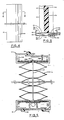
- the right side track 20, which is adapted to be fastened to the right window jamb 72 is comprised of an elongated extruded channel member having a web 52, front flange 54, and rear flange 56.
- a front lip 55 extends inwardly from the distal end of front flange 54, and a similar lip 57 extends inwardly from the distal end of rear flange 56.
- Exterior slots 58, 59 are provided to retain weather stripping 30 therein for sealing against the window jamb 72.
- the right seal element 32 is positioned in the interior 50 of side track 20. It is comprised of a web 34 positioned against the open end of intermediate honeycomb cell 210 to close and seal the end thereof.
- a front leg portion 36 extends from a fold at the front edge of the web 34 and at an acute angle thereto into contact with the web 52 of side track 20.
- a rear leg 38 extends from the fold at the rear edge of web 34 into contact with the web 52 of side track 20.
- the edge seal element 32 is preferably fabricated of a fairly rigid, resilient thin film material with its natural cross-sectional shape similar to that shown in Figure 3 with a curved web portion 34 and divergent leg members 36, 38. In this manner, when the honeycomb panel 16 is assembled with the side track 20 and edge seal element 32, the edge seal element 32 will assume the shape shown in Figure 6 with its web 34 flat against the open end of the cell 210. The legs 36, 38 then tend to bias the web 34 inwardly toward the cell 210 to maintain constant contact and effective closure against the open end of cell 210. Further, this contact is maintained in a sliding manner between the web 34 and the honeycomb panel 16 as the honeycomb panel 16 slides upwardly and downwardly within the track 20.
- the left side track 18 is adapted for attachment to the left window jamb 71 and is comprised of a rib 42, front flange 44, and rear flange 46.
- a front lip 45 extends inwardly from front flange 44, and a rear lip 47 extends inwardly from rear flange 46 for retaining the edge seal element 22 within the interior 40 of side track 18.
- the edge seal element 22 is comprised of a rib 24 for closing and sealing the open left ends of the cells in honeycomb panel 16, and front and rear leg portions 26, 28 for biasing the rib 24 against the honeycomb panel 16.
- the side tracks 18, 20 not only serve to retain the edge seal elements 22, 32 in proper position, but they also retain the edges of the honeycomb panel 16 in proper alignment and serve as a guide track for the sill rail 14 in which the sill rail 14 can slide up and down as the panel 16 is raised and lowered.
- the left and right cords 62, 64 extend respectively through left and right side tracks 18, 20 respectively, instead of through the honeycomb panel 16.
- This alternate cord arrangement is preferred when the honeycomb cell material 16 is fabricated of a somewhat transparent material that would expose cords running through the centre of the honeycomb panel 16 as described in the preferred embodiment and shown in Figure 3.
- the cords 62, 64 would be more concealed in the side tracks 18, 20 then if they were running through honeycomb panel 16 in such transparent materials. It should be noted, however, that honeycomb panel installations that do not utilize the side tracks 18, 20 and edge seals 22, 32, the embodiment described in Figure 3 with the cord running through the honeycomb panel 16 would be required.
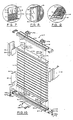
- the preferred alternate parallel bar system 310 illustrated in Figure 10, is appropriate for many non-conventional uses, such as those illustrated in Figures 7, 8, and 9. As shown in Figure 10, this parallel bar embodiment is quite similar to the preferred vertical drop system 10 described above. It has a head rail 12, attached to a window jamb by mounting brackets 290. The expandable honeycomb panel 16 is attached to the head rail 12 in the same manner as that described for the preferred embodiment 10 described above. Also, a moveable sill rail 14 is attached to the other end of the honeycomb panel 16 as described in the preferred vertical drop embodiment 10, above. Also, the side tracks 18, 20 and edge seal elements 22, 32 are the same as those described in the preferred vertical drop embodiment 10, above.
- this parallel bar system embodiment 310 utilizes two independent cords 320, 324 anchored at the top to head rail 12 and at the bottom to opposite sides of the window sill 73. More specifically, left cord 320 is anchored at the top by a bead or knot 321 to guide plate 200. Guide plate 200 is fastened to the head rail 12 by a screw 204, as described in the preferred vertical drop embodiment 10 above. Left cord 220 extends downwardly through the panel 16 and through a second guide plate 214 and into the interior of sill rail 14. Guide plate 214 is held in position by screw 18. From guide plate 314, the left cord 320 passes through the interior of sill rail 14 and out hole 173 and right end cap 170. Outside end cap 170, the left cord 320 is anchored to the window sill 73 by an anchor member 322.
- the right cord 324 is anchored at the top to right guide plate 202 which is attached to head rail 12 by screw 205. It extends downwardly through panel 16 and into sill rail 14 through a hole 317 in a lower guide plate 316 attached to sill rail 14 by a screw 319. At that point, right cord 324 passes to the left through the interior of sill rail 14 and out hole 163 and left end plate 160. Outside end plate 160, the right cord 324 is anchored to the left side of window sill 173 by anchor member 326. The bottom of web 324 has notch 312 therein to slip over the anchor member 326 without interfering with the functioning of edge seal element 22.
- a handle 328 is attached to the front flange 134 of sill rail 14 for moving sill rail 14 upwardly and downwardly within the side tracks 18, 20. Because of the arrangement and positioning of the left and right cords 320, 324 with their respective anchors at opposite sides of sill rail 14, sill rail 14 can be moved easily upwardly and downwardly within the guide tracks 18 - 20. However, this arrangement also always maintains the sill rail 14 in parallel relation to the head rail 12, thereby keeping the entire panel system in proper alignment within the tracks 18, 20. Also, this arrangement provides just the friction in the cords to keep the sill rail 14 at any position desired by the user between the window sill 73 and the head rail 12. It can also be appreciated that pulley blocks could be used in place of the guide plates 314, 316 in this embodiment if excessive friction or cord wear is encountered, particularly in large installations.
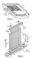
- FIG. 11 Another alternate preferred embodiment in the form of a continuous loop system 330 can also be used for the non-conventional installations in which the preferred vertical drop system 10, described above, are not appropriate.
- FIG 11 Such an installation in a skylight is shown in Figure 11, wherein the continuous loop honeycomb panel system 330, according to the present invention, is mounted in a horizontal overhead position.
- This alternate preferred embodiment continuous loop system is best described in reference to Figures 11 and 12.
- a head rail 12 is fastened by brackets 390 to a window frame, as described in the preferred embodiments above.
- the honeycomb panel 16 is also attached to the head rail 12, as described above.
- a moveable sill rail 14 is attached to the opposite end of the honeycomb panel 16, again, as described in the preferred embodiments above. This part of the arrangement is virtually the same as the vertical drop embodiment 10, described above and illustrated in Figure 3.
- a secondary sill rail 332 is permanently attached to the sill or frame of the window adjacent the main sill rail 14.
- a reverse operating cord 335 comprised of a left cord 336 and a right cord 338, extends through a hole 348 into the interior of secondary sill rail 332.
- the left cord 336 passes out the left end through hole 345 in end plate 344 and upwardly to the left end of main sill rail 14. It passes through hole 163 and end plate 160 into the interior of main sill rail 14 and is anchored or terminated therein at a tension spring 216.
- the right cord 338 passes out the right end of secondary sill rail 332 through a hole 347 and end plate 346.
- a pole 340 with a hook 342 on the end thereof can be used to engage the joiner ball to pull the cords back and forth, thereby moving the honeycomb panel 16 one way and then the other.
Abstract
Description
- The present invention is related to moveable insulation and decorative window coverings, and more particularly to methods for assembling mounting and sealing moveable honeycomb blind constructions.
- The increased cost of energy and general raising of energy consciousness over the past decade has resulted in a developing interest in methods and apparatus for covering windows, not only for privacy and aesthetic effects, but also for insulation effect. Such window coverings, of course, have to be moveable so that they can be raised and lowered during different times of the day and during different seasons. In order to satisfy the needs of most users, they also have to be aesthetically pleasing, durable, easy to install, adjustable, and relatively inexpensive.
- This combination of desirable features, including a moveable material having a significant insulating effect and being aesthetically pleasing in appearance has not been an easily attained goal. There have been a number of different developments in this area, such as the inflatable curtains disclosed in US Patent No. 4187896 issued to R. Shore and in US Patent No. 4453584, issued to R. Steele. Another kind of development in this area includes the use of expandable honeycomb panels having a plurality of cellular tubes fastened together to form panels. US Patent No. 4450027, issued to W. Colson, is one example of such material. Such expandable honeycomb material appears at the present time at least, to hold the most promise for meeting the goals of moveable insulation that is both aesthetically pleasing and has a significant insulating effect. It is also more conducive to mass production and mass marketing to consumers.
- There are a number of problems in the use of cellular material for moveable insulation that have heretofore not been solved. For example, most of the past effort up to this time has been directed to developing economical and suitable processes for fabricating honeycomb insulation panels that are capable of enduring long life and severe environments of high temperature and exposure to sunlight and moisture, while always maintaining an aesthetically pleasing appearance. However, prior to this invention, methods and apparatus utilized for mounting such expandable honeycomb insulation panels over windows have been rather crude and not conducive to mass marketing or installation by individual home owners or relatively unskilled persons. Further, in order to maximise the insulating effect of the expandable honeycomb panels, the open ends of the tubular cell sections must be sealed. Prior to this invention, there was no suitable method and apparatus for mounting expandable honeycomb insulation panels over windows with the edges sealed while maintaining an aesthetically pleasing appearance and being easily operable.
- US-A-4307768 discloses a honeycomb blind construction in which each end of the blind is permanently attached to a support member. It is therefore not possible to alter the length of the blind. Furthermore, the ends of the honeycomb elements are not completely sealed so allowing the passage of air therethrough.
- US-A-4450027 discloses a further honeycomb blind construction comprising a plurality of elongate parallel hollow cell structures linked to one another to form a panel, the cell structures themselves being arranged in a single row each having oppositely disposed common cell areas with the immediately adjacent cell structures and an elongate rail.
- The assembly of such a construction is time consuming.
- According to one aspect of the present invention there is provided a method of sealing expandable honeycomb insulation comprising a plurality of elongate parallel hollow cell structures formed together into a panel with the lateral edges of said panel formed of open ends of said cell structures, characterised by the steps of positioning an elongated seal strip along each lateral edge of said panel, in such a manner that the seal strip closes and seals the open ends of said cell structures while allowing said panel to slide upward and downward in relation to said seal strips, and biasing said seal strips against the respective lateral edges of said panel.
- According to another aspect of the present invention there is provided an expandable honeycomb blind construction comprising a plurality of elongated parallel cell structures formed together into a panel with the lateral edges of said panel formed of open ends of said cell structures, characterised in that edge seal means are provided for closing and sealing the open ends of said cell structures, said edge seal means including an elongated strip positioned adjacent the lateral edge of the honeycomb panel along substantially the entire length of said panel and means biassing said strip into sliding contact with the lateral edge of said panel.
- The edge seals effectively close and seal the ends of the tubular insulation cells, while allowing free expansion and contraction of the honeycomb panel for moving the panel over and away from the window openings over which it is mounted.
- The following description is given merely by way of example with reference to the accompanying drawings, in which:
- Figure 1 is a perspective view of a honeycomb window covering unit according to the present invention;
- Figure 2 is a front elevation view of a honeycomb window covering unit according to the present invention mounted over a window, the illustration therein being with the insulating shade unit half drawn over the window;
- Figure 3 is a perspective exploded view of the preferred vertical drop embodiment of the honeycomb window covering unit according to the present invention;
- Figure 4 is a side elevation view of the honeycomb winder covering unit of the present invention showing primarily the side track thereof;
- Figure 5 is a cross-sectional view of the honeycomb window covering unit taken along lines 5-5 of Figure 2;
- Figure 6 is a cross-sectional view of the side track and edge seal taken along lines 6-6 of Figure 4;
- Figure 7 is a perspective view of an alternate embodiment honeycomb window covering unit according to the present invention with the head rail fastened to the bottom jamb of the window frame and moveable upwardly over the window;
- Figure 8 is a partial perspective view of another alternate embodiment honeycomb window covering unit that is moveable horizontally over the window;
- Figure 9 is another alternate embodiment installation of the honeycomb window covering unit of the present invention of an off-vertical or slanted window or skylight arrangement;
- Figure 10 is an exploded perspective view of an alternate preferred parallel bar system embodiment of the present invention suitable for use in installations such as those shown in Figures 7, 8, and 9;
- Figure 11 is a perspective view of another preferred alternate continuous loop system honeycomb window covering unit mounted in a horizontal ceiling skylight installation; and
- Figure 12 is an exploded perspective view of the alternate embodiment continuous loop system honeycomb window covering unit of the present invention.
- An expandable
honeycomb insulation panel 16 is comprised of a plurality oftubular cell sections 210 adhered or fastened together in parallel relationship to each other so that they can be compressed and coned together or expanded and extended apart. This honeycombcellular panel 16 is mounted in and suspended from ahead rail 12. Amoveable sill rail 14 is fastened to the bottom of thehoneycomb panel 16 for weight and to provide structural integrity to the bottom of the panel. A lift mechanism is provided for pulling thesill rail 14 upwardly to collapse the honeycomb panel between thesill rail 14 andhead rail 12 when it is preferred to have the window uncovered and to drop thesill rail 14 downwardly to expand thehoneycomb panel 16 over the window when it is desired to cover the window. A pull cord 60, shown in Figure 1, is provided for this purpose as will be described in more detail below. - In order to provide a significant insulating quality, the open ends of the
tubular honeycomb cells 210 of thehoneycomb panel 16 must be closed and sealed. With each such tubular cell sealed at the ends, a plurality of dead air spaces are provided by the expandedhoneycomb panel 16 between the window and the interior environment. Further, a suitable seal at the edges of thehoneycomb panel 16 should prevent infiltration from the window behind thehoneycomb panel 16 into the interior environment of a room. - Such edge seals are provided in the present invention by
edge seal elements right side tracks window covering unit 10 to further decrease the possibility of infiltration of air from one side of the honeycomb window covering unit to the other. - The preferred embodiment edge seals, according to the present invention, are best described in reference to Figures 1, 2, 3, 4, and 6. Left and
right side tracks honeycomb panel 16. The left and rightedge seal elements side tracks honeycomb panel 16. For example, theright side track 20, which is adapted to be fastened to theright window jamb 72, is comprised of an elongated extruded channel member having a web 52,front flange 54, and rear flange 56. Afront lip 55 extends inwardly from the distal end offront flange 54, and asimilar lip 57 extends inwardly from the distal end of rear flange 56. Exterior slots 58, 59 are provided to retain weather stripping 30 therein for sealing against thewindow jamb 72. - Referring primarily now to Figure 6, and secondarily to Figures 2 and 3, the
right seal element 32 is positioned in theinterior 50 ofside track 20. It is comprised of aweb 34 positioned against the open end ofintermediate honeycomb cell 210 to close and seal the end thereof. Afront leg portion 36 extends from a fold at the front edge of theweb 34 and at an acute angle thereto into contact with the web 52 ofside track 20. Likewise, arear leg 38 extends from the fold at the rear edge ofweb 34 into contact with the web 52 ofside track 20. - The
edge seal element 32 is preferably fabricated of a fairly rigid, resilient thin film material with its natural cross-sectional shape similar to that shown in Figure 3 with acurved web portion 34 anddivergent leg members honeycomb panel 16 is assembled with theside track 20 andedge seal element 32, theedge seal element 32 will assume the shape shown in Figure 6 with itsweb 34 flat against the open end of thecell 210. Thelegs web 34 inwardly toward thecell 210 to maintain constant contact and effective closure against the open end ofcell 210. Further, this contact is maintained in a sliding manner between theweb 34 and thehoneycomb panel 16 as thehoneycomb panel 16 slides upwardly and downwardly within thetrack 20. Further, when thehoneycomb panel 16 is pulled upwardly, as shown in Figure 2, thelips edge seal element 32 in position in theside track 20 until thehoneycomb panel 16 is dropped downwardly again in sliding contact with theweb 34. In this manner, a constant and effective sliding closure and seal is maintained between theweb 34 and thecells 210 ofhoneycomb panel 16 regardless of the position in whichhoneycomb panel 16 is placed over the window W. - For further description, it is noted that in Figure 6, the glue line or attachment between the
cell 210 and the next adjacent cell above 210 is indicated at 212. Also, theright cord 64 is shown extending through ahole 214 incell 210 in a typical manner. - Likewise, the
left side track 18 is adapted for attachment to theleft window jamb 71 and is comprised of arib 42,front flange 44, andrear flange 46. A front lip 45 extends inwardly fromfront flange 44, and arear lip 47 extends inwardly fromrear flange 46 for retaining theedge seal element 22 within theinterior 40 ofside track 18. Theedge seal element 22 is comprised of arib 24 for closing and sealing the open left ends of the cells inhoneycomb panel 16, and front andrear leg portions rib 24 against thehoneycomb panel 16. The side tracks 18, 20 not only serve to retain theedge seal elements honeycomb panel 16 in proper alignment and serve as a guide track for thesill rail 14 in which thesill rail 14 can slide up and down as thepanel 16 is raised and lowered. - In a variation, the left and
right cords 62, 64 extend respectively through left and right side tracks 18, 20 respectively, instead of through thehoneycomb panel 16. This alternate cord arrangement is preferred when thehoneycomb cell material 16 is fabricated of a somewhat transparent material that would expose cords running through the centre of thehoneycomb panel 16 as described in the preferred embodiment and shown in Figure 3. Thecords 62, 64 would be more concealed in the side tracks 18, 20 then if they were running throughhoneycomb panel 16 in such transparent materials. It should be noted, however, that honeycomb panel installations that do not utilize the side tracks 18, 20 and edge seals 22, 32, the embodiment described in Figure 3 with the cord running through thehoneycomb panel 16 would be required. - Some installations are not conducive to the preferred
vertical drop embodiment 10 described above. For example, in some installations, as shown in Figure 7, it is desirable to have thehoneycomb panel 16 attached to thesill 12 with the moveable end on top so that the panel can be moved upwardly and downwardly from the sill. Also, as shown in Figure 8, it is sometimes desirable to mount thehoneycomb panel 16 for horizontal movement over awindow 2. Further, some windows are positioned at a non-vertical slant, as shown in Figure 9. - The preferred alternate
parallel bar system 310, illustrated in Figure 10, is appropriate for many non-conventional uses, such as those illustrated in Figures 7, 8, and 9. As shown in Figure 10, this parallel bar embodiment is quite similar to the preferredvertical drop system 10 described above. It has ahead rail 12, attached to a window jamb by mountingbrackets 290. Theexpandable honeycomb panel 16 is attached to thehead rail 12 in the same manner as that described for thepreferred embodiment 10 described above. Also, amoveable sill rail 14 is attached to the other end of thehoneycomb panel 16 as described in the preferredvertical drop embodiment 10, above. Also, the side tracks 18, 20 andedge seal elements vertical drop embodiment 10, above. - However, rather than utilizing a pull cord 60, as described above, this parallel
bar system embodiment 310 utilizes twoindependent cords 320, 324 anchored at the top to headrail 12 and at the bottom to opposite sides of thewindow sill 73. More specifically,left cord 320 is anchored at the top by a bead orknot 321 to guideplate 200.Guide plate 200 is fastened to thehead rail 12 by ascrew 204, as described in the preferredvertical drop embodiment 10 above. Left cord 220 extends downwardly through thepanel 16 and through asecond guide plate 214 and into the interior ofsill rail 14.Guide plate 214 is held in position byscrew 18. From guide plate 314, theleft cord 320 passes through the interior ofsill rail 14 and outhole 173 andright end cap 170.Outside end cap 170, theleft cord 320 is anchored to thewindow sill 73 by ananchor member 322. - The right cord 324 is anchored at the top to
right guide plate 202 which is attached to headrail 12 byscrew 205. It extends downwardly throughpanel 16 and intosill rail 14 through ahole 317 in a lower guide plate 316 attached tosill rail 14 by a screw 319. At that point, right cord 324 passes to the left through the interior ofsill rail 14 and outhole 163 andleft end plate 160.Outside end plate 160, the right cord 324 is anchored to the left side ofwindow sill 173 byanchor member 326. The bottom of web 324 has notch 312 therein to slip over theanchor member 326 without interfering with the functioning ofedge seal element 22. - A
handle 328 is attached to thefront flange 134 ofsill rail 14 for movingsill rail 14 upwardly and downwardly within the side tracks 18, 20. Because of the arrangement and positioning of the left andright cords 320, 324 with their respective anchors at opposite sides ofsill rail 14,sill rail 14 can be moved easily upwardly and downwardly within the guide tracks 18 - 20. However, this arrangement also always maintains thesill rail 14 in parallel relation to thehead rail 12, thereby keeping the entire panel system in proper alignment within thetracks sill rail 14 at any position desired by the user between thewindow sill 73 and thehead rail 12. It can also be appreciated that pulley blocks could be used in place of the guide plates 314, 316 in this embodiment if excessive friction or cord wear is encountered, particularly in large installations. - Another alternate preferred embodiment in the form of a
continuous loop system 330 can also be used for the non-conventional installations in which the preferredvertical drop system 10, described above, are not appropriate. Such an installation in a skylight is shown in Figure 11, wherein the continuous loophoneycomb panel system 330, according to the present invention, is mounted in a horizontal overhead position. This alternate preferred embodiment continuous loop system is best described in reference to Figures 11 and 12. In this continuous loop system, ahead rail 12 is fastened by brackets 390 to a window frame, as described in the preferred embodiments above. Thehoneycomb panel 16 is also attached to thehead rail 12, as described above. Further, amoveable sill rail 14 is attached to the opposite end of thehoneycomb panel 16, again, as described in the preferred embodiments above. This part of the arrangement is virtually the same as thevertical drop embodiment 10, described above and illustrated in Figure 3. - In this continuous
loop system embodiment 330, however, asecondary sill rail 332 is permanently attached to the sill or frame of the window adjacent themain sill rail 14. Areverse operating cord 335, comprised of aleft cord 336 and aright cord 338, extends through ahole 348 into the interior ofsecondary sill rail 332. Theleft cord 336 passes out the left end through hole 345 inend plate 344 and upwardly to the left end ofmain sill rail 14. It passes throughhole 163 andend plate 160 into the interior ofmain sill rail 14 and is anchored or terminated therein at a tension spring 216. Likewise, theright cord 338 passes out the right end ofsecondary sill rail 332 through a hole 347 and end plate 346. It then passes upwardly and into the right end of themain sill rail 14 throughhole 173 inright end plate 170. Insidesill rail 14, theright cord 338 also anchors or terminates at the tension spring 216. The outer end ofreverse operating cord 335 is joined by a joiner ball comprised of an upper section 67 and alower section 68 together with the forward operating cord 60. - In operation, when cord 60 is pulled out, it will pull
main sill rail 14 upwardly in the conventional manner. Asmain sill rail 14 moves upwardly, it will pullreverse operating cord 335 into thesecondary sill rail 332. Then, when it is desired to move themain sill rail 14 downwardly, thereverse operating cord 335 can be pulled out ofsecondary sill rail 332. This outward pull onreverse operating cord 335 will movemain sill rail 14 downwardly, thus pullingoperating cord 16 into thehead rail 12. The tension spring 216 maintains the cords in proper tension and alignment so that no loose ends or unparallel action occurs. - When the
honeycomb panel installation 30 is positioned out of reach, such as in an overhead skylight shown in Figure 11, apole 340 with ahook 342 on the end thereof can be used to engage the joiner ball to pull the cords back and forth, thereby moving thehoneycomb panel 16 one way and then the other.
Claims (4)
Priority Applications (1)
| Application Number | Priority Date | Filing Date | Title |
|---|---|---|---|
| AT89113014T ATE84599T1 (en) | 1984-08-07 | 1985-07-19 | LOADING DEVICE IN HONEYCOMB CONSTRUCTION AND METHOD OF MANUFACTURE. |
Applications Claiming Priority (2)
| Application Number | Priority Date | Filing Date | Title |
|---|---|---|---|
| US06638860 US4647488B1 (en) | 1984-08-07 | 1984-08-07 | Method and apparatus for mounting and sealing honeycomb insulation |
| US638860 | 1984-08-07 |
Related Parent Applications (1)
| Application Number | Title | Priority Date | Filing Date |
|---|---|---|---|
| EP85201207.9 Division | 1985-07-19 |
Publications (3)
| Publication Number | Publication Date |
|---|---|
| EP0341760A2 true EP0341760A2 (en) | 1989-11-15 |
| EP0341760A3 EP0341760A3 (en) | 1990-08-22 |
| EP0341760B1 EP0341760B1 (en) | 1993-01-13 |
Family
ID=24561764
Family Applications (3)
| Application Number | Title | Priority Date | Filing Date |
|---|---|---|---|
| EP85201207A Expired - Lifetime EP0171116B1 (en) | 1984-08-07 | 1985-07-19 | Honeycomb blind constructions and method of assembling honeycomb blind constructions |
| EP89113015A Expired - Lifetime EP0340815B1 (en) | 1984-08-07 | 1985-07-19 | Honeycomb blind constructions |
| EP89113014A Expired - Lifetime EP0341760B1 (en) | 1984-08-07 | 1985-07-19 | Honeycomb blind constructions and method of assembling honeycomb blind constructions |
Family Applications Before (2)
| Application Number | Title | Priority Date | Filing Date |
|---|---|---|---|
| EP85201207A Expired - Lifetime EP0171116B1 (en) | 1984-08-07 | 1985-07-19 | Honeycomb blind constructions and method of assembling honeycomb blind constructions |
| EP89113015A Expired - Lifetime EP0340815B1 (en) | 1984-08-07 | 1985-07-19 | Honeycomb blind constructions |
Country Status (10)
| Country | Link |
|---|---|
| US (2) | US4647488B1 (en) |
| EP (3) | EP0171116B1 (en) |
| JP (1) | JPH0689624B2 (en) |
| KR (1) | KR910005066B1 (en) |
| AT (3) | ATE84599T1 (en) |
| AU (2) | AU572678B2 (en) |
| CA (3) | CA1265039A (en) |
| DE (3) | DE3576379D1 (en) |
| ES (2) | ES288581Y (en) |
| GB (4) | GB8518775D0 (en) |
Cited By (2)
| Publication number | Priority date | Publication date | Assignee | Title |
|---|---|---|---|---|
| EP0558154A2 (en) * | 1992-02-28 | 1993-09-01 | Shigeki Fukuchi | Cord controlled window shades |
| US9057219B1 (en) | 2011-08-30 | 2015-06-16 | Newell Window Furnishings, Inc. | Window covering with integrated side track |
Families Citing this family (118)
| Publication number | Priority date | Publication date | Assignee | Title |
|---|---|---|---|---|
| US5246053A (en) * | 1985-09-25 | 1993-09-21 | Nergeco | Riser for a vertically-opening door |
| AU580452B2 (en) * | 1985-10-21 | 1989-01-12 | Tass Zorbas | Blind |
| US4631217A (en) * | 1985-10-25 | 1986-12-23 | Hunter Douglas Inc. | Honeycomb structure with Z-folded material and method of making same |
| US4762159A (en) * | 1986-09-18 | 1988-08-09 | Cooper Industries | Shade system |
| US4807686A (en) * | 1987-02-25 | 1989-02-28 | Comfortex Corporation | Shade system |
| WO1988007345A1 (en) * | 1987-03-25 | 1988-10-06 | Verosol Usa, Inc. | Shade and method for the manufacture thereof |
| US5205333A (en) * | 1987-03-25 | 1993-04-27 | Verosol Usa Inc. | Shade and method for the manufacture thereof |
| US5176192A (en) * | 1987-03-25 | 1993-01-05 | Verosol Usa Inc. | Shade and bottomrail therefor |
| US4974656A (en) * | 1987-03-25 | 1990-12-04 | Verosol Usa Inc. | Shade and method for the manufacture thereof |
| US4852627A (en) * | 1987-04-13 | 1989-08-01 | Daylighting, Inc. | Closed loop control system for shade assembly |
| US5205891A (en) * | 1987-08-28 | 1993-04-27 | Hunter Douglas, Inc. | Method for manufacturing an expandable collapsible product |
| US4943454A (en) * | 1987-08-28 | 1990-07-24 | Hunter Douglas, Inc. | Expandable collapsible product and method and apparatus for its manufacture |
| US4862941A (en) * | 1987-10-06 | 1989-09-05 | Hunter Douglas Inc. | Vertical shade assembly |
| US4850414A (en) * | 1987-12-14 | 1989-07-25 | Solarium Zytco Ltd. | Motorized blind assembly |
| GB2213855A (en) * | 1987-12-22 | 1989-08-23 | Raymond John Luget | Window blind |
| US4953610A (en) * | 1989-03-17 | 1990-09-04 | Ultimate Window Coverings, Inc. | Double window shade assembly with independent shade movement |
| USRE34273E (en) * | 1989-03-17 | 1993-06-08 | Ultimate Window Coverings, Inc. | Double window shade assembly with independent shade movement |
| US4934436A (en) * | 1989-06-30 | 1990-06-19 | Comfortex Corporation | Suspension and actuation system for specialty window shades |
| DE8913557U1 (en) * | 1989-11-16 | 1989-12-28 | Rehau Ag + Co, 8673 Rehau, De | |
| USD456196S1 (en) | 1990-10-24 | 2002-04-30 | Hunter Douglas Inc. | Fabric light control window covering |
| US5313999A (en) * | 1990-10-24 | 1994-05-24 | Hunter Douglas Inc. | Fabric light control window covering |
| US6001199A (en) * | 1990-10-24 | 1999-12-14 | Hunter Douglas Inc. | Method for manufacturing a fabric light control window covering |
| US5178200A (en) * | 1990-12-14 | 1993-01-12 | Halge Hagen | Venetian-or pleated blinds, particularly for multiple pane insulating glass window |
| USRE35926E (en) * | 1990-12-14 | 1998-10-20 | Nordicon Develop Aps | Venetian- or pleated blinds, particularly for multiple pane insulating glass window |
| US5141041A (en) * | 1991-09-20 | 1992-08-25 | Comfortex Corporation | Stepped multi-cellular window shade |
| US5205334A (en) * | 1991-10-03 | 1993-04-27 | Verosol Usa Inc. | Double layer shade |
| US5392832A (en) * | 1991-12-19 | 1995-02-28 | Hunter Douglas Inc. | Covering assembly for architectural openings |
| US5287908A (en) * | 1991-12-19 | 1994-02-22 | Hunter Douglas Inc. | Window covering assembly |
| WO1994000663A1 (en) * | 1992-06-23 | 1994-01-06 | Tecom Services Ag | Device to control folding of window shades made of pleated pet sun protection films |
| US5377737A (en) * | 1992-12-17 | 1995-01-03 | Seiki Hanbai Co., Ltd. | Screen retractor mechanism |
| CA2111063C (en) * | 1993-02-18 | 1996-04-23 | Gary M. Bach | Reinforced cell material |
| US6019864A (en) * | 1993-04-26 | 2000-02-01 | Fashion Tech, Inc. | Composite window covering and method and apparatus for manufacture thereof |
| US5390720A (en) * | 1993-07-09 | 1995-02-21 | Hunter Douglas, Inc. | Tubular cell window covering with undulations along the length of the cells |
| US5509250A (en) * | 1993-09-20 | 1996-04-23 | Skylights, Incorporated | Structural panel useful for skylights |
| JP2895737B2 (en) * | 1994-02-24 | 1999-05-24 | セイキ販売株式会社 | Folding screen device |
| CA2144220C (en) * | 1994-03-08 | 2005-08-23 | Siegfried Joachim Schon | Retractable blind or shade assembly |
| US5701940A (en) * | 1994-03-10 | 1997-12-30 | Cooper Industries, Inc. | Cellular shade |
| CA2144280A1 (en) * | 1994-03-10 | 1995-09-11 | James Arthur Ford | Cellular shade material |
| US5531257A (en) | 1994-04-06 | 1996-07-02 | Newell Operating Company | Cordless, balanced window covering |
| US6412537B1 (en) | 1999-01-12 | 2002-07-02 | Newell Operating Company | Bottom rail weight and balancing system |
| US6330899B1 (en) | 1994-04-06 | 2001-12-18 | Newell Window Furnishings. Inc. | Cordless balanced window covering |
| US5626175A (en) * | 1995-04-03 | 1997-05-06 | Keys; Donald B. | Plastic film indoor window insulation kit with reinforced access ports |
| US5655590A (en) * | 1995-05-18 | 1997-08-12 | Bryant; David C. | Window blind with storage rail |
| CA2190796C (en) | 1995-11-22 | 2002-07-02 | Wendell B. Colson | Ceiling cladding system |
| US5897730A (en) * | 1996-07-16 | 1999-04-27 | Teh Yor Industrial Co., Ltd. | Method for producing shade material |
| US5706876A (en) * | 1996-07-29 | 1998-01-13 | Lysyj; Phillip A. | Cordless, roller bar cellular shade |
| US5813447A (en) * | 1996-07-29 | 1998-09-29 | Lysyj; Phillip A. | Cordless cellular and pleated shade |
| US5794679A (en) * | 1997-01-15 | 1998-08-18 | Marvingardens, Ltd. | Canopy structure for sun shade |
| DE60000356T2 (en) | 1999-02-05 | 2003-01-23 | Turnils Ab Alingsaas | headband |
| US6289965B1 (en) | 2000-02-11 | 2001-09-18 | Newell Operating Company | Take-up drum for a cordless shade counterbalance |
| US6571853B1 (en) | 2000-07-06 | 2003-06-03 | Newell Window Furnishings, Inc. | Cordless blind having variable resistance to movement |
| US6725897B2 (en) | 2000-08-22 | 2004-04-27 | Newell Window Furnishings, Inc. | Variable friction device for a cordless blind |
| US6607020B1 (en) * | 2000-11-01 | 2003-08-19 | Vkr Holding A/S | Screening arrangement and method for installation of such in a curb for a skylight |
| US7228797B1 (en) * | 2000-11-28 | 2007-06-12 | Sundberg-Ferar, Inc. | Cordless blind |
| US6648049B2 (en) | 2000-12-19 | 2003-11-18 | David C. Bryant | Cord lock and method for adjusting the length of a window blind assembly |
| US6644375B2 (en) | 2001-01-09 | 2003-11-11 | Newell Window Furnishings | Cordless blind brake |
| US7025107B2 (en) | 2001-07-31 | 2006-04-11 | Newell Window Furnishings, Inc. | One-way tensioning mechanism for cordless blind |
| TW534204U (en) * | 2002-09-30 | 2003-05-21 | Nien Made Entpr Co Ltd | Venetian blinds with shutter guises |
| MXPA05004684A (en) * | 2002-10-31 | 2005-11-17 | Newell Window Furnishings Inc | Temporary window covering. |
| WO2004048737A1 (en) * | 2002-11-21 | 2004-06-10 | Newell Window Furnishings, Inc. | Temporary window covering |
| CA2511769C (en) * | 2002-12-10 | 2008-06-10 | Ren Judkins | Fabric covered rail for pleated shade |
| US6941996B2 (en) * | 2003-05-21 | 2005-09-13 | Springs Window Fashions Lp | Double shade with modular end caps and method of assembling same |
| US20040250963A1 (en) * | 2003-06-11 | 2004-12-16 | Ching Feng Blinds Ind. Co., Ltd. | Non-pull cord operated multi-layer venetian blind |
| CN102061878B (en) | 2003-12-22 | 2016-03-30 | 亨特道格拉斯有限公司 | As the retractible shading piece of building apertured cover |
| ITRM20030606A1 (en) * | 2003-12-30 | 2005-06-30 | Francesco Lucia Di | SELF-LOCKING OPENING AND CLOSING DEVICE, |
| US20060027336A1 (en) * | 2004-07-22 | 2006-02-09 | Shih-Ming Lin | Double-layer roman shade |
| US7360573B2 (en) * | 2005-03-03 | 2008-04-22 | Teh Yor Co., Ltd. | Securement insert for a head rail |
| TWI277511B (en) * | 2005-08-17 | 2007-04-01 | Metal Ind Res & Dev Ct | Honeycomb insulating panel and method of making the same |
| US8572911B1 (en) * | 2006-02-13 | 2013-11-05 | University Of Akron Research Foundation | Inflatable structure with internal support |
| US7984743B2 (en) * | 2006-09-07 | 2011-07-26 | Newell Window Furnishing, Inc. | Shade construction |
| KR100822176B1 (en) * | 2007-01-19 | 2008-04-16 | 변태웅 | Method of mounting blinds between two windows and the structure thereof |
| BRPI0807969B1 (en) * | 2007-01-24 | 2018-06-12 | Reynolds Consumer Products, Inc. | PORTABLE PORTABLE FLOOR SYSTEM AND METHOD FOR ASSEMBLING SUCH FLOOR SYSTEM |
| CA2676141C (en) | 2007-01-24 | 2014-10-28 | Reynolds Consumer Products, Inc. | Clamp device for portable porous pavement system |
| US20090008040A1 (en) * | 2007-07-05 | 2009-01-08 | Shih-Ming Lin | Hive-Shaped Blind |
| FR2918698B1 (en) * | 2007-07-12 | 2009-10-02 | Maviflex Sa | MODULAR AMOUNT FOR FLEXIBLE CURTAIN HANDLING DOOR |
| US8087445B2 (en) * | 2009-06-23 | 2012-01-03 | Newell Window Furnishings, Inc. | Spring motor and window covering |
| CN102240151B (en) | 2010-05-10 | 2013-08-28 | 德侑股份有限公司 | Double-honeycomb structure for window curtain and manufacturing process thereof |
| EP2395194A1 (en) * | 2010-06-14 | 2011-12-14 | Stila A/S | A system and method for blocking light |
| MX361607B (en) | 2010-06-23 | 2018-12-05 | Hunter Douglas Inc Star | Plastic double-cell covering for architectural openings. |
| US8459326B2 (en) | 2011-01-06 | 2013-06-11 | Hunter Douglas, Inc. | Cellular shade assembly and method for constructing same |
| USD691392S1 (en) | 2011-05-04 | 2013-10-15 | Hunter Douglas Inc. | Fabric panel |
| USD691391S1 (en) | 2011-05-04 | 2013-10-15 | Hunter Douglas Inc. | Fabric panel |
| USD691394S1 (en) | 2011-05-04 | 2013-10-15 | Hunter Douglas Inc. | Fabric panel |
| USD691487S1 (en) | 2011-05-04 | 2013-10-15 | Hunter Douglas Inc. | Fabric panel |
| USD691395S1 (en) | 2011-05-04 | 2013-10-15 | Hunter Douglas Inc. | Fabric panel |
| USD691486S1 (en) | 2011-05-04 | 2013-10-15 | Hunter Douglas Inc. | Fabric panel for coverings for architectural openings |
| USD691393S1 (en) | 2011-05-04 | 2013-10-15 | Hunter Douglas Inc. | Fabric panel |
| USD691396S1 (en) | 2011-05-04 | 2013-10-15 | Hunter Douglas Inc. | Fabric panel |
| US9062493B2 (en) * | 2011-05-16 | 2015-06-23 | Maxxmar Inc. | Blind assembly with two blind head rail |
| US9885812B2 (en) | 2011-08-26 | 2018-02-06 | Hunter Douglas Inc. | Feature for inhibiting light stripe between cellular elements in a covering for an architectural opening |
| CA2844518C (en) | 2011-08-26 | 2019-10-29 | Hunter Douglas Inc. | Double pleat cellular shade element |
| JP5877681B2 (en) * | 2011-10-11 | 2016-03-08 | トーソー株式会社 | Mounting structure for mounting different types of screens on rails |
| US9028081B2 (en) | 2011-12-01 | 2015-05-12 | Flatiron Research Group, LLC | Removable window insulator |
| US9357868B2 (en) | 2012-12-06 | 2016-06-07 | Hunter Douglas Inc. | Skew adjustment mechanism for a window covering |
| US9759008B2 (en) * | 2012-12-06 | 2017-09-12 | Hunter Douglas Inc. | End cap for a rail for a window covering |
| USD734060S1 (en) | 2013-04-01 | 2015-07-14 | Hunter Douglas Inc. | Cellular shade component |
| USD734061S1 (en) | 2013-04-01 | 2015-07-14 | Hunter Douglas Inc. | Portion of a cellular shade component |
| WO2014199023A1 (en) * | 2013-06-11 | 2014-12-18 | Flexoma | Device for blacking-out a picture window actuated by an inflatable element |
| USD743183S1 (en) * | 2013-06-27 | 2015-11-17 | Oceanair Marine Ltd | Extendable window blind |
| DE102013111815A1 (en) * | 2013-10-25 | 2015-04-30 | Windhager Handelsgesmbh | Plisseejalousie |
| USD750395S1 (en) | 2014-05-02 | 2016-03-01 | Hunter Douglas Inc. | Covering for an architectural opening having a vane with a pattern |
| USD740588S1 (en) | 2014-05-02 | 2015-10-13 | Hunter Douglas Inc. | Covering for an architectural opening having a vane with a pattern |
| USD751319S1 (en) | 2014-05-02 | 2016-03-15 | Hunter Douglas Inc. | Covering for an architectural opening having a sheet with a pattern |
| KR200475525Y1 (en) * | 2014-08-18 | 2014-12-08 | 주식회사 알엠케이 | Fire window for idc and containment system comprising the same |
| USD764836S1 (en) * | 2014-09-08 | 2016-08-30 | Hunter Douglas Inc. | Covering for an architectural opening having multiple columns of double cells |
| WO2017197152A1 (en) * | 2016-05-12 | 2017-11-16 | Rollease Acmeda, Inc. | Window covering system |
| JP6512185B2 (en) * | 2016-07-19 | 2019-05-15 | 積水ハウス株式会社 | Shielding curtain and window structure |
| WO2018165129A1 (en) * | 2017-03-09 | 2018-09-13 | Conway Matthew B | Window shade device |
| US10730367B2 (en) | 2017-06-27 | 2020-08-04 | Bauer Products, Inc. | Vent shade assembly |
| US10596883B2 (en) * | 2017-06-27 | 2020-03-24 | Bauer Products, Inc. | Vent shade assembly |
| JP7011491B2 (en) * | 2018-02-26 | 2022-01-26 | 株式会社ニチベイ | blind |
| KR102101971B1 (en) * | 2018-11-13 | 2020-05-29 | 남경이 | Automatic honeycomb blind apparatus |
| CN109591434B (en) * | 2018-12-03 | 2020-06-02 | 航天科工武汉磁电有限责任公司 | Honeycomb sandwich panel edge sealing method |
| JP7233973B2 (en) * | 2019-03-05 | 2023-03-07 | 株式会社ニチベイ | Blind frames and blinds |
| JP7247022B2 (en) * | 2019-05-29 | 2023-03-28 | 株式会社ニチベイ | BLIND |
| USD944020S1 (en) * | 2019-10-03 | 2022-02-22 | Molo Design, Ltd. | Adjustable partition |
| USD951662S1 (en) * | 2019-10-03 | 2022-05-17 | Molo Design, Ltd. | Adjustable partition |
| US20220325575A1 (en) * | 2021-04-13 | 2022-10-13 | Li-Ming Cheng | Foldable sheer shade |
Citations (3)
| Publication number | Priority date | Publication date | Assignee | Title |
|---|---|---|---|---|
| DE1683352A1 (en) * | 1966-06-13 | 1969-10-16 | Paulick Hans Joachim | Window or door blind |
| AT363239B (en) * | 1978-05-16 | 1981-07-27 | Schenker Storen Maschf | REEL SLAT STORE |
| US4307768A (en) * | 1978-02-21 | 1981-12-29 | Anmar Industries, Inc. | Energy conserving insulative window shade |
Family Cites Families (21)
| Publication number | Priority date | Publication date | Assignee | Title |
|---|---|---|---|---|
| US1229523A (en) * | 1915-05-29 | 1917-06-12 | George B French | Adjustable closure for window or other openings or passages. |
| US1907597A (en) * | 1932-04-21 | 1933-05-09 | Edward F Sibbert | Curtain operating device |
| US2201356A (en) * | 1938-11-21 | 1940-05-21 | Gertrude H Terrell | Window fixture |
| US2674295A (en) * | 1950-12-13 | 1954-04-06 | Method of and means fob expanding | |
| GB1366961A (en) * | 1972-02-11 | 1974-09-18 | Beauty Blind Ltd | Roller blind assemblies |
| DK133073C (en) * | 1974-04-29 | 1976-08-30 | M O H Rasmussen | HEAT INSULATING CURTAIN |
| US3963549A (en) * | 1974-06-13 | 1976-06-15 | Max Otto Henri Rasmussen | Method and apparatus for producing continuous surface elements |
| US4045911A (en) * | 1975-10-01 | 1977-09-06 | Ware R Louis | Versatile horticultural growth apparatus |
| GB1554159A (en) * | 1976-06-18 | 1979-10-17 | Bestobell Home Prod Ltd | Curtain assemblies |
| US4187896A (en) * | 1977-09-15 | 1980-02-12 | Shore Ronald H | Self-inflating solar curtain |
| FI57161C (en) * | 1978-03-21 | 1980-06-10 | Suominen Heikki S | FOERFARANDE FOER FRAMSTAELLNING AV ETT TAECKE FOER VAERMEISOLATION |
| US4388354A (en) * | 1978-03-21 | 1983-06-14 | Suominen Heikki S | Tubular insulating curtain and method of manufacture |
| US4247583A (en) * | 1978-10-30 | 1981-01-27 | Roy Paul D | Insulating structure with polygonal cells |
| US4347887A (en) * | 1980-10-06 | 1982-09-07 | Brown Lawrence P | Thermal shutters |
| US4453584A (en) * | 1981-05-22 | 1984-06-12 | Steele Richard S | Sealing system for movable insulation |
| DE3221109A1 (en) * | 1981-11-14 | 1983-05-26 | Walter Paul KG, 7252 Weil der Stadt | LOUVRE |
| US4450027A (en) * | 1982-08-09 | 1984-05-22 | Colson Wendell B | Method and apparatus for fabricating honeycomb insulating material |
| US4500380A (en) * | 1983-12-19 | 1985-02-19 | Bova Joseph D | Method and apparatus for continuous production of expandable honeycomb |
| US4631217A (en) * | 1985-10-25 | 1986-12-23 | Hunter Douglas Inc. | Honeycomb structure with Z-folded material and method of making same |
| US4732630A (en) * | 1986-03-26 | 1988-03-22 | Thermocell, Ltd. | Method for producing expandable honeycomb material |
| US4862941A (en) * | 1987-10-06 | 1989-09-05 | Hunter Douglas Inc. | Vertical shade assembly |
-
1984
- 1984-08-07 US US06638860 patent/US4647488B1/en not_active Expired - Lifetime
-
1985
- 1985-07-19 DE DE8585201207T patent/DE3576379D1/en not_active Expired - Fee Related
- 1985-07-19 AT AT89113014T patent/ATE84599T1/en active
- 1985-07-19 EP EP85201207A patent/EP0171116B1/en not_active Expired - Lifetime
- 1985-07-19 AT AT89113015T patent/ATE75519T1/en not_active IP Right Cessation
- 1985-07-19 AT AT85201207T patent/ATE50819T1/en not_active IP Right Cessation
- 1985-07-19 DE DE8989113015T patent/DE3585956D1/en not_active Expired - Fee Related
- 1985-07-19 EP EP89113015A patent/EP0340815B1/en not_active Expired - Lifetime
- 1985-07-19 EP EP89113014A patent/EP0341760B1/en not_active Expired - Lifetime
- 1985-07-19 DE DE8989113014T patent/DE3586997T2/en not_active Expired - Fee Related
- 1985-07-25 GB GB858518775A patent/GB8518775D0/en active Pending
- 1985-08-06 ES ES1985288581U patent/ES288581Y/en not_active Expired
- 1985-08-06 CA CA000488278A patent/CA1265039A/en not_active Expired - Lifetime
- 1985-08-06 KR KR1019850005668A patent/KR910005066B1/en not_active IP Right Cessation
- 1985-08-06 AU AU45825/85A patent/AU572678B2/en not_active Ceased
- 1985-08-07 JP JP60173961A patent/JPH0689624B2/en not_active Expired - Lifetime
-
1986
- 1986-03-17 ES ES1986292998U patent/ES292998Y/en not_active Expired
- 1986-05-27 GB GB08612864A patent/GB2175339B/en not_active Expired
- 1986-06-04 GB GB08613595A patent/GB2175034B/en not_active Expired
- 1986-06-04 GB GB08613599A patent/GB2175340B/en not_active Expired
- 1986-08-27 US US06900967 patent/US4675060B1/en not_active Expired - Lifetime
-
1988
- 1988-07-14 AU AU19062/88A patent/AU585197B2/en not_active Ceased
-
1989
- 1989-09-05 CA CA000610254A patent/CA1275909C/en not_active Expired - Lifetime
- 1989-09-05 CA CA000610373A patent/CA1280962C/en not_active Expired - Lifetime
Patent Citations (3)
| Publication number | Priority date | Publication date | Assignee | Title |
|---|---|---|---|---|
| DE1683352A1 (en) * | 1966-06-13 | 1969-10-16 | Paulick Hans Joachim | Window or door blind |
| US4307768A (en) * | 1978-02-21 | 1981-12-29 | Anmar Industries, Inc. | Energy conserving insulative window shade |
| AT363239B (en) * | 1978-05-16 | 1981-07-27 | Schenker Storen Maschf | REEL SLAT STORE |
Cited By (3)
| Publication number | Priority date | Publication date | Assignee | Title |
|---|---|---|---|---|
| EP0558154A2 (en) * | 1992-02-28 | 1993-09-01 | Shigeki Fukuchi | Cord controlled window shades |
| EP0558154A3 (en) * | 1992-02-28 | 1994-01-12 | Shigeki Fukuchi | |
| US9057219B1 (en) | 2011-08-30 | 2015-06-16 | Newell Window Furnishings, Inc. | Window covering with integrated side track |
Also Published As
Similar Documents
| Publication | Publication Date | Title |
|---|---|---|
| EP0341760A2 (en) | Honeycomb blind constructions and method of assembling honeycomb blind constructions | |
| JP3772992B2 (en) | Sealable cover | |
| AU651938B2 (en) | Double layer shade | |
| US4037639A (en) | Thermal barrier | |
| US20220106833A1 (en) | Coil brush curtain assembly | |
| US5123474A (en) | Roll-up closure device | |
| US5752557A (en) | Sealable curtain | |
| CA2242637C (en) | Window covering | |
| JP5197958B2 (en) | Retractable shade with vanes that deform like it collapses | |
| US5692550A (en) | Cellular shade material | |
| US20070000620A1 (en) | Control system for vertical covering for architectural openings | |
| US20120318465A1 (en) | Insulating shade for covering an architectural opening | |
| US5222540A (en) | Articulated window covering panels | |
| US2621724A (en) | biergstrom | |
| NZ223943A (en) | Honeycomb panel blind sealed in side tracking channels enclosing seal biassing devices | |
| US7240714B2 (en) | System for suspending a free-hanging covering for an architectural opening | |
| EP2358966B1 (en) | Conservatory roof window with screen mountable inside or outside |
Legal Events
| Date | Code | Title | Description |
|---|---|---|---|
| PUAI | Public reference made under article 153(3) epc to a published international application that has entered the european phase |
Free format text: ORIGINAL CODE: 0009012 |
|
| 17P | Request for examination filed |
Effective date: 19890715 |
|
| AC | Divisional application: reference to earlier application |
Ref document number: 171116 Country of ref document: EP |
|
| AK | Designated contracting states |
Kind code of ref document: A2 Designated state(s): AT BE DE FR IT NL SE |
|
| RIN1 | Information on inventor provided before grant (corrected) |
Inventor name: SCHNEBLY, JOHN T. Inventor name: STEELE, RICHARD S. Inventor name: COLSON, WENDELL B. |
|
| PUAL | Search report despatched |
Free format text: ORIGINAL CODE: 0009013 |
|
| AK | Designated contracting states |
Kind code of ref document: A3 Designated state(s): AT BE DE FR IT NL SE |
|
| 17Q | First examination report despatched |
Effective date: 19910902 |
|
| GRAA | (expected) grant |
Free format text: ORIGINAL CODE: 0009210 |
|
| RAP1 | Party data changed (applicant data changed or rights of an application transferred) |
Owner name: THERMOCELL, LTD. |
|
| AC | Divisional application: reference to earlier application |
Ref document number: 171116 Country of ref document: EP |
|
| AK | Designated contracting states |
Kind code of ref document: B1 Designated state(s): AT BE DE FR IT NL SE |
|
| REF | Corresponds to: |
Ref document number: 84599 Country of ref document: AT Date of ref document: 19930115 Kind code of ref document: T |
|
| REF | Corresponds to: |
Ref document number: 3586997 Country of ref document: DE Date of ref document: 19930225 |
|
| ITF | It: translation for a ep patent filed |
Owner name: STUDIO ING. ALFREDO RAIMONDI |
|
| ET | Fr: translation filed | ||
| PGFP | Annual fee paid to national office [announced via postgrant information from national office to epo] |
Ref country code: FR Payment date: 19930709 Year of fee payment: 9 |
|
| PGFP | Annual fee paid to national office [announced via postgrant information from national office to epo] |
Ref country code: AT Payment date: 19930713 Year of fee payment: 9 |
|
| PGFP | Annual fee paid to national office [announced via postgrant information from national office to epo] |
Ref country code: SE Payment date: 19930715 Year of fee payment: 9 |
|
| PGFP | Annual fee paid to national office [announced via postgrant information from national office to epo] |
Ref country code: DE Payment date: 19930726 Year of fee payment: 9 |
|
| PGFP | Annual fee paid to national office [announced via postgrant information from national office to epo] |
Ref country code: NL Payment date: 19930731 Year of fee payment: 9 |
|
| PGFP | Annual fee paid to national office [announced via postgrant information from national office to epo] |
Ref country code: BE Payment date: 19930901 Year of fee payment: 9 |
|
| PLBE | No opposition filed within time limit |
Free format text: ORIGINAL CODE: 0009261 |
|
| STAA | Information on the status of an ep patent application or granted ep patent |
Free format text: STATUS: NO OPPOSITION FILED WITHIN TIME LIMIT |
|
| 26N | No opposition filed | ||
| PG25 | Lapsed in a contracting state [announced via postgrant information from national office to epo] |
Ref country code: AT Effective date: 19940719 |
|
| PG25 | Lapsed in a contracting state [announced via postgrant information from national office to epo] |
Ref country code: SE Effective date: 19940720 |
|
| PG25 | Lapsed in a contracting state [announced via postgrant information from national office to epo] |
Ref country code: BE Effective date: 19940731 |
|
| BERE | Be: lapsed |
Owner name: THERMOCELL LTD Effective date: 19940731 |
|
| EUG | Se: european patent has lapsed |
Ref document number: 89113014.8 Effective date: 19950210 |
|
| PG25 | Lapsed in a contracting state [announced via postgrant information from national office to epo] |
Ref country code: NL Effective date: 19950201 |
|
| NLV4 | Nl: lapsed or anulled due to non-payment of the annual fee | ||
| PG25 | Lapsed in a contracting state [announced via postgrant information from national office to epo] |
Ref country code: FR Effective date: 19950331 |
|
| PG25 | Lapsed in a contracting state [announced via postgrant information from national office to epo] |
Ref country code: DE Effective date: 19950401 |
|
| EUG | Se: european patent has lapsed |
Ref document number: 89113014.8 |
|
| REG | Reference to a national code |
Ref country code: FR Ref legal event code: ST |