EP0349214A2 - Weapon training systems - Google Patents
Weapon training systems Download PDFInfo
- Publication number
- EP0349214A2 EP0349214A2 EP89306385A EP89306385A EP0349214A2 EP 0349214 A2 EP0349214 A2 EP 0349214A2 EP 89306385 A EP89306385 A EP 89306385A EP 89306385 A EP89306385 A EP 89306385A EP 0349214 A2 EP0349214 A2 EP 0349214A2
- Authority
- EP
- European Patent Office
- Prior art keywords
- weapon
- target
- detector
- detector means
- entry aperture
- Prior art date
- Legal status (The legal status is an assumption and is not a legal conclusion. Google has not performed a legal analysis and makes no representation as to the accuracy of the status listed.)
- Withdrawn
Links
Images
Classifications
-
- F—MECHANICAL ENGINEERING; LIGHTING; HEATING; WEAPONS; BLASTING
- F41—WEAPONS
- F41G—WEAPON SIGHTS; AIMING
- F41G3/00—Aiming or laying means
- F41G3/26—Teaching or practice apparatus for gun-aiming or gun-laying
- F41G3/2616—Teaching or practice apparatus for gun-aiming or gun-laying using a light emitting device
- F41G3/2622—Teaching or practice apparatus for gun-aiming or gun-laying using a light emitting device for simulating the firing of a gun or the trajectory of a projectile
- F41G3/2666—Teaching or practice apparatus for gun-aiming or gun-laying using a light emitting device for simulating the firing of a gun or the trajectory of a projectile with means for selecting or varying PRF or time coding of the emitted beam
-
- F—MECHANICAL ENGINEERING; LIGHTING; HEATING; WEAPONS; BLASTING
- F41—WEAPONS
- F41G—WEAPON SIGHTS; AIMING
- F41G3/00—Aiming or laying means
- F41G3/26—Teaching or practice apparatus for gun-aiming or gun-laying
- F41G3/2616—Teaching or practice apparatus for gun-aiming or gun-laying using a light emitting device
- F41G3/2622—Teaching or practice apparatus for gun-aiming or gun-laying using a light emitting device for simulating the firing of a gun or the trajectory of a projectile
- F41G3/265—Teaching or practice apparatus for gun-aiming or gun-laying using a light emitting device for simulating the firing of a gun or the trajectory of a projectile with means for selecting or varying the shape or the direction of the emitted beam
-
- F—MECHANICAL ENGINEERING; LIGHTING; HEATING; WEAPONS; BLASTING
- F41—WEAPONS
- F41G—WEAPON SIGHTS; AIMING
- F41G3/00—Aiming or laying means
- F41G3/26—Teaching or practice apparatus for gun-aiming or gun-laying
- F41G3/2616—Teaching or practice apparatus for gun-aiming or gun-laying using a light emitting device
- F41G3/2622—Teaching or practice apparatus for gun-aiming or gun-laying using a light emitting device for simulating the firing of a gun or the trajectory of a projectile
- F41G3/2655—Teaching or practice apparatus for gun-aiming or gun-laying using a light emitting device for simulating the firing of a gun or the trajectory of a projectile in which the light beam is sent from the weapon to the target
Definitions
- This invention relates to weapon training systems, and is more particularly but not exclusively concerned with weapon training systems for simulating the use of direct fire weapons such as rifles, light machine guns and other small arms.
- One well known form of weapon training system for simulating the use of a direct fire weapon comprises a laser source adapted to be secured to the weapon and arranged to produce a relatively narrow pulsed laser beam which is directed along, or at a predetermined angle to, the boresight axis of the weapon.
- the laser beam is scanned in a predetermined pattern with respect to the boresight axis over the target and the area immediately around it.
- a detector on the target detects the incidence of the beam and signals that the beam has been detected back to the firer of the weapon via a radio link, or a retro-reflector on the target reflects the beam back to a detector at the weapon.
- the range from the weapon to the target can be calculated from the time interval between the production of a given laser pulse at the weapon and the production of a radio or detector signal at the weapon indicating that that particular laser pulse was incident on the target.
- the accuracy of the aim of the weapon during its simulated firing can be computed from a combination of the elevation of the weapon, the measured range to the target and the position of the target in the predetermined scanning pattern of the beam.
- Typical examples of such weapon training systems are described in our United Kingdom Patent Specifications Nos. 1 228 143, 1 451 192 and 2 174 789.
- This prior art form of weapon training system provides excellent results, but can be rather complex and/or expensive when considered in the context of simulating the use of small arms. At least part of this complexity and expense is due to the necessity of providing a return path from the target to the weapon (ie the aforementioned radio link or retroreflection of the beam), in order to enable the range from the weapon to the target to be measured. It is therefore an object of the present invention to provide a weapon training system which avoids the necessity for this return path, while still providing realistic and useful simulation of the use of the weapon.
- the range from the weapon to the target can be computed from this relatively small difference in the detected modulation frequencies, because the difference is a function of the angle subtended by the predetermined extent of the entry aperture of the detector means at the weapon, and therefore a function of the range from the weapon to the target.
- range can be computed at the target, without the necessity of the aforementioned return path from the target to the weapon.
- the system further comprises a second detector means adapted to be secured to the target, the second detector means having an entry aperture whose extent along the direction of scan of the beam is substantially less than that of the firstmentioned detector means, and the circuit being coupled to the output of the second detector means and responsive to the modulation frequencies detected thereby to correct the range computation for the angular extent of the beam in the scan direction.
- the second detector means having an entry aperture with substantially no appreciable angular extent in the scan direction, is effectively operative (in combination with the circuit) to determine the angular extent of the beam.
- the entry aperture of the first detector means is an annulus of predetermined diameter, and coaxially surrounds the entry aperture of the second detector means.
- the scanning means is arranged, in use, to scan the beam vertically downward from an initial orientation in which the beam is substantially aligned with the boresight of the weapon.
- the circuit is preferably arranged to compute the elevation of the weapon with respect to the target from the mean of the modulation frequencies detected by one of the first and second detector means, and to determine the accuracy with which the weapon was aimed at the target from the relationship between the computed elevation and the computed range.
- the scanning means preferably comprises a piezoelectric member arranged to support at least that portion of the source from which the beam is emitted, and means for applying a ramp signal to the piezoelectric member so as to cause it to flex and thereby scan the beam.
- the modulating means preferably comprises a variable frequency oscillator whose frequency is controlled by said ramp signal.
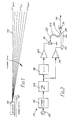
- the laser projector of Figure 1 is indicated at 10, and is shown attached to the barrel 12 of a weapon such as a rifle.
- the laser projector 10 is arranged to produce a narrow pulsed laser beam 14, which can be scanned vertically downwardly, in use, from an initial orientation in which it is aligned with the boresight of the weapon, ie with the bore of the barrel 12, while having its pulse repetition frequency (or prf) increased as a function of the scan angle.
- the projector 10 comprises a gallium arsenide laser diode 16 which is connected to be energised by a voltage-controlled oscillator (VCO) 18 via a pulse-shaping amplifier 20, so that it produces laser output pulses at the operating frequency of the oscillator 18.
- VCO voltage-controlled oscillator
- the laser output pulses produced by the laser diode 16 enter one end 22 of an optical fibre 24, whose other end 26 is secured to one end 28 of a piezoelectric finger 30.
- the exit plane of the end 26 of the fibre 24 is positioned in the focal plane of a fixed collimating lens 31, which collimates the laser pulses leaving the end 26 of the fibre and thus forms them into the aforementioned narrow pulsed laser beam 14.
- the piezoelectric finger 30 is mounted within the projector 10 so that its end 28 is capable of flexing or bending vertically upwardly with respect to the remainder of the finger when a suitable DC voltage is applied to the finger. It will be appreciated that this upward flexing of the finger 30 causes the beam 14 formed by the lens 31 to be deflected vertically downwardly.
- the finger 30 and the lens 31 are mounted within the projector 10 such that in the relaxed or unflexed state of the finger, the beam 14 is precisely aligned with the bore of the barrel 12 of the weapon.
- the operating frequency of the VCO 18 is controlled by a linear ramp generator 32, which is also connected, via a suitable amplifier 34, to control the bending or flexing of the finger 30.
- the ramp generator 32 is triggered into producing its output ramp by a trigger circuit 36, which is in turn triggered by a microphone 38 positioned to respond to the firing of a blank round by the weapon.
- the weapon loaded with blank rounds, is aimed by its user, typically a soldier taking part in a training exercise, with a ballistic elevation appropriate to the range to the target as estimated by the user, typically up to 1000 metres, at a target equipped as will be described hereinafter.
- the weapon is then fired, thus firing a blank round, which triggers the ramp generator 32 via the microphone 38 and the trigger circuit 36.
- the ramp generator 32 starts the VCO 18, and sweeps its frequency linearly upwardly, typically from 1.1 kHz to 11 kHz over about 300 milliseconds.
- the ramp generator 32 simultaneously causes the end 28 of the piezoelectric finger 30 to flex progressively vertically upwardly, thus scanning the laser beam 14 produced by the lens 31 vertically downwardly at a substantially uniform angular rate, typically about 1 mrad every 15 msec, through a total of about 20 mrad in all.
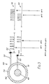
- the target at which the weapon employing the projector 10 of Figures 1 and 2 is aimed is provided with at least one detector unit of the form shown somewhat schematically at 40 in Figure 3.
- this target is another soldier taking part in the training exercise, wearing a harness carrying one or more of the detector units 40.
- the detector unit 40 comprises first and second photoelectric detectors 42,44 having respective entry apertures 46,48.
- the entry aperture 46 is annular, typically about 60 mm in diameter, and coaxially surrounds the entry aperture 48.
- Each of the entry apertures 46,48 communicates with its respective photoelectric detector 42,44 via a respective bundle of optical fibres indicated diagrammatically at 50,52, one end of each bundle being shaped to conform to its respective entry aperture, and the other being shaped for optimum communication with its respective photoelectric detector.
- the detectors 42,44 are matched such that they are as equally sensitive to the incidence of the beam 14 on their respective entry apertures 46,48 as possible.
- the pulsed laser beam 14 scans vertically downwardly over the detector unit 40, it will first of all by incident on the top 54 of the annular entry aperture 46 of the photoelectric detector 42, then also briefly incident on the much smaller entry aperture 48 of the photoelectric detector 44 (while still, of course, incident on the entry aperture 46), before finally leaving the bottom 56 of the annular entry aperture 46.
- the two photoelectric detectors 42, 44 thus produce respective output pulse trains, representative of the laser pulses incident on their respective entry apertures 46,48, as shown at 58 and 60 in Figure 3.
- These pulse trains have maximum and minimum prfs indicated in Figure 3 as prf4, prf1, and prf3, prf2, such that prf4 > prf3 > prf2 > prf1, and are applied to the circuit of Figure 4.
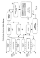
- the circuit of Figure 4 comprises first and second pulse interval timers 70, 72 connected to the respective outputs of the photoelectric detectors 42,44 respectively.
- Each of the pulse interval timers 70,72 measures each time interval between the leading edges of successive pulses from its respective photoelectric detector, by counting the number of clock pulses from a crystal oscillator (not shown) operating at a reference frequency of typically 15 MHz, each count being inversely proportional to the prf of the pulses over the time interval measured.
- the maximum count attained by each of the timers 70,72 is entered in respective registers 74,76, while the minimum count attained by each of the timers 70,72 is entered in respective registers 78,80.
- the average of the maximum and minimum counts attained by the timer 72 ie the timer receiving the pulse train from the detector 44 having the smaller entry aperture 48 (which can effectively be regarded as a point aperture), is determined in an averaging circuit 82, and is a function of the elevation of the barrel 12 of the weapon with respect to the detector unit 40. This average is applied to a circuit 83 which computes the elevation of the barrel 12, and applies the computed value to one input 84 of comparison circuit 86. Additionally, the difference between the respective maximum counts in registers 74,76 is formed in subtraction circuit 88, the difference between the respective minimum counts in registers 78,80 is formed in subtraction circuit 90, and the difference between the respective differences in subtraction circuits 88,90 is formed in subtraction circuit 92.
- the difference formed in subtraction circuit 92 is representative of the angle subtended by the annular entry aperture 46 of the photoelectric detector 42 at the projector 10 on the weapon, as corrected for the angular width of the beam 14 in the scan direction, and thus a function of the range from the weapon to the target.
- the difference value generated by the circuit 92 is applied to a circuit 93 which computes the range from the weapon to the target, and applies the computed value to a second input 94 of the circuit 86.
- the circuit 86 compares the computed range value at the input 94 with the computed elevation value at its input 84, and determines, from stored data concerning the ballistic characteristics of the weapon, the accuracy with which the weapon was aimed at the target.
- the target can be caused to emit some kind of hit signal, eg an audible signal or a flashing light signal, and/or disabled.
- some kind of hit signal eg an audible signal or a flashing light signal
- the target is another soldier wearing a harness having one or more of the detector units 40 attached thereto, and the soldier also has a weapon with a projector 10 mounted thereon
- the audible signal or flashing light can be arranged to remain energised until the soldier lies down to simulate the effect of being hit, and his weapon can be disabled to prevent him from taking any further part in the training exercise. This permits realistic training exercises to be held in complete safety.
- the described weapon training system has a number of advantages.
- the range from the weapon to the target is computed at the target, avoiding the necessity of a two-way communication link between the weapon and the target.
- the circuitry required at the target to compute the range is relatively simple digital circuitry, eg counters, gates, registers, subtracters, comparators, and therefore relatively inexpensive: although a microprocessor can be used, in most cases its use is not essential.
- Another advantage lies in the form of the detector unit 40, in particular the annular entry aperture 46.
- the shape of this aperture 46 means that the detector unit 40 is wholly insensitive to rotation of the detector unit about the axis of the aperture, and relatively insensitive to small changes (up to say 30°) in the inclination of the plane of the aperture from the vertical.
- the use of the detector 44 coupled to the central, substantially point, entry aperture 48 enables the system to correct for variations in the angular width of the beam 14 in the vertical direction. This is especially important in view of the fact that the laser 16 in the projector 10 has to be of relatively low power in order to be eye-safe, which means that the apparent beam width of the beam 14 can vary considerably, eg with weather conditions, over the operational range of the system.
- the matching of the sensitivity of the detector 44 to that of the detector 42 ensures that the detector 44 "sees" the same angular beam width as the detector 42, and is thus able to correctly compensate the angular measurement performed by the detector 42 for the angular width of the beam 14.
- the weapon training system can be used to simulate the use of weapons other than rifles, eg light automatic weapons having a firing rate of up to say 120 rounds per minute.
- the projector 10 can be arranged to include in the emitted laser pulses extra pulses which encode, by pulse position coding, information concerning weapon and/or ammunition type. These extra coding pulses can be interleaved between the normal, already-mentioned pulses, with a timing that enables them to be readily discriminated by appropriate time-controlled gating circuitry at the target. Once discriminated at the target, the information represented by the extra coding can be used in the circuit 86 to select an appropriate set of stored ballistic data for use in the accuracy of aim determination.
- the detector 42 with its vertically extended entry aperture 46 can be replaced by a vertical array of detectors, or even by two vertically spaced detectors, each with its own entry aperture: thus in this specification, the expression "entry aperture” as applied to one or more detectors is intended to refer to the space between the two furthest apart points in the entry or inlet to the detector or detectors which communicate with (ie admit light to) the detector or detectors, irrespective of whether the entire space between the points actually communicates with the detector or detectors.
- the entry aperture of the detector 42 be vertically extended, to co-operate with the vertical scanning of the beam 14, other orientations of the scanning of the beam and of the entry aperture of the detector 42 are possible, while still permitting the range from the weapon to the target to be computed. And if the beam width of the beam 14 is particularly well defined and known, eg because a relatively high power beam can be used, then the detector 44 can perhaps be omitted.
Landscapes
- Engineering & Computer Science (AREA)
- Radar, Positioning & Navigation (AREA)
- General Engineering & Computer Science (AREA)
- Aiming, Guidance, Guns With A Light Source, Armor, Camouflage, And Targets (AREA)
Abstract
A weapon simulator, particularly for simulating small arms, comprises a laser projector (10) for attachment to the weapon (12). Firing the weapon (12) initiates the production of a narrow, pulsed, beam (14) by the laser, and this beam (14) is scanned vertically downwardly while its PRF is varied as a function of scan angle. The weapon/ammunition type can also be encoded in the laser pulses. The beam (14) is received by a spatially diverse pair of detectors on the target, typically comprising a first detector having an annular entry aperture covering about 6 cm in the vertical direction, and a second detector disposed in the centre of the annular entry aperture of the first. The central detector effectively determines the width of the beam, thus permitting the range from the weapon to the target to be computed from the beam width and the difference in the PRF detected at the start and finish of the illumination of the first detector. The elevation angle of the weapon with respect to the target is computed from the mean PRF detected by the central detector. Finally, the accuracy of aim of the weapon (ie whether the firing resulted in a hit or a miss) is determined from a combination of the range, the weapon elevation angle, and the weapon/ammunition type.
Description
- This invention relates to weapon training systems, and is more particularly but not exclusively concerned with weapon training systems for simulating the use of direct fire weapons such as rifles, light machine guns and other small arms.
- One well known form of weapon training system for simulating the use of a direct fire weapon comprises a laser source adapted to be secured to the weapon and arranged to produce a relatively narrow pulsed laser beam which is directed along, or at a predetermined angle to, the boresight axis of the weapon. Upon aiming and simulated firing of the weapon towards a target, the laser beam is scanned in a predetermined pattern with respect to the boresight axis over the target and the area immediately around it. As the beam passes over the target, either a detector on the target detects the incidence of the beam and signals that the beam has been detected back to the firer of the weapon via a radio link, or a retro-reflector on the target reflects the beam back to a detector at the weapon. In either case, the range from the weapon to the target can be calculated from the time interval between the production of a given laser pulse at the weapon and the production of a radio or detector signal at the weapon indicating that that particular laser pulse was incident on the target. Thus the accuracy of the aim of the weapon during its simulated firing can be computed from a combination of the elevation of the weapon, the measured range to the target and the position of the target in the predetermined scanning pattern of the beam. Typical examples of such weapon training systems are described in our United Kingdom Patent Specifications Nos. 1 228 143, 1 451 192 and 2 174 789.
- This prior art form of weapon training system provides excellent results, but can be rather complex and/or expensive when considered in the context of simulating the use of small arms. At least part of this complexity and expense is due to the necessity of providing a return path from the target to the weapon (ie the aforementioned radio link or retroreflection of the beam), in order to enable the range from the weapon to the target to be measured. It is therefore an object of the present invention to provide a weapon training system which avoids the necessity for this return path, while still providing realistic and useful simulation of the use of the weapon.
- According to the present invention, a weapon training system for simulating the use of a weapon against a target comprises:
a source of electromagnetic radiation adapted to be secured to the weapon, said source being arranged to produce a narrow beam of radiation which is directed generally along the aiming line of the weapon;
means for scanning said beam in a predetermined direction transversely of said aiming line;
means for modulating the beam at a frequency which is a function of the angular position of said beam along said scan direction; and
detector means adapted to be secured to the target, for receiving the beam when the weapon is aimed at the target;
wherein the detector means has an entry aperture which is extended by a predetermined amount along the direction of scan of the beam;
and further comprising a circuit coupled to the output of the detector means and responsive to the respective modulation frequencies of the beam at the start and at the end of the illumination of the entry aperture of the detector means by the beam to compute the range from the weapon to the target. - It will be understood that the range from the weapon to the target can be computed from this relatively small difference in the detected modulation frequencies, because the difference is a function of the angle subtended by the predetermined extent of the entry aperture of the detector means at the weapon, and therefore a function of the range from the weapon to the target. Thus range can be computed at the target, without the necessity of the aforementioned return path from the target to the weapon.
- In a preferred embodiment of the invention, the system further comprises a second detector means adapted to be secured to the target, the second detector means having an entry aperture whose extent along the direction of scan of the beam is substantially less than that of the firstmentioned detector means, and the circuit being coupled to the output of the second detector means and responsive to the modulation frequencies detected thereby to correct the range computation for the angular extent of the beam in the scan direction.
- It will be understood that this correction is made possible because the second detector means, having an entry aperture with substantially no appreciable angular extent in the scan direction, is effectively operative (in combination with the circuit) to determine the angular extent of the beam.
- Advantageously, the entry aperture of the first detector means is an annulus of predetermined diameter, and coaxially surrounds the entry aperture of the second detector means.
- Preferably, the scanning means is arranged, in use, to scan the beam vertically downward from an initial orientation in which the beam is substantially aligned with the boresight of the weapon. In this case, the circuit is preferably arranged to compute the elevation of the weapon with respect to the target from the mean of the modulation frequencies detected by one of the first and second detector means, and to determine the accuracy with which the weapon was aimed at the target from the relationship between the computed elevation and the computed range.
- The scanning means preferably comprises a piezoelectric member arranged to support at least that portion of the source from which the beam is emitted, and means for applying a ramp signal to the piezoelectric member so as to cause it to flex and thereby scan the beam.
- The modulating means preferably comprises a variable frequency oscillator whose frequency is controlled by said ramp signal.
- The invention will now be described, by way of example only, with reference to the accompanying drawings, of which:
- Figure 1 shows a laser projector forming part of a weapon training system in accordance with the present invention;
- Figure 2 shows part of the projector of Figure 1 in a little more detail;
- Figure 3 shows somewhat schematically a detector unit forming a further part of the weapon training system incorporating the projector of Figures 1 and 2; and
- Figure 4 is a block diagram of a circuit coupled to the detector unit of Figure 3.
- The laser projector of Figure 1 is indicated at 10, and is shown attached to the
barrel 12 of a weapon such as a rifle. Thelaser projector 10 is arranged to produce a narrowpulsed laser beam 14, which can be scanned vertically downwardly, in use, from an initial orientation in which it is aligned with the boresight of the weapon, ie with the bore of thebarrel 12, while having its pulse repetition frequency (or prf) increased as a function of the scan angle. - To this end, and as shown in Figure 2, the
projector 10 comprises a galliumarsenide laser diode 16 which is connected to be energised by a voltage-controlled oscillator (VCO) 18 via a pulse-shaping amplifier 20, so that it produces laser output pulses at the operating frequency of theoscillator 18. The laser output pulses produced by thelaser diode 16 enter oneend 22 of anoptical fibre 24, whoseother end 26 is secured to oneend 28 of apiezoelectric finger 30. The exit plane of theend 26 of thefibre 24 is positioned in the focal plane of a fixedcollimating lens 31, which collimates the laser pulses leaving theend 26 of the fibre and thus forms them into the aforementioned narrowpulsed laser beam 14. - The
piezoelectric finger 30 is mounted within theprojector 10 so that itsend 28 is capable of flexing or bending vertically upwardly with respect to the remainder of the finger when a suitable DC voltage is applied to the finger. It will be appreciated that this upward flexing of thefinger 30 causes thebeam 14 formed by thelens 31 to be deflected vertically downwardly. Thefinger 30 and thelens 31 are mounted within theprojector 10 such that in the relaxed or unflexed state of the finger, thebeam 14 is precisely aligned with the bore of thebarrel 12 of the weapon. - The operating frequency of the
VCO 18 is controlled by alinear ramp generator 32, which is also connected, via asuitable amplifier 34, to control the bending or flexing of thefinger 30. Theramp generator 32 is triggered into producing its output ramp by atrigger circuit 36, which is in turn triggered by amicrophone 38 positioned to respond to the firing of a blank round by the weapon. - In use, the weapon, loaded with blank rounds, is aimed by its user, typically a soldier taking part in a training exercise, with a ballistic elevation appropriate to the range to the target as estimated by the user, typically up to 1000 metres, at a target equipped as will be described hereinafter. The weapon is then fired, thus firing a blank round, which triggers the
ramp generator 32 via themicrophone 38 and thetrigger circuit 36. Theramp generator 32 starts theVCO 18, and sweeps its frequency linearly upwardly, typically from 1.1 kHz to 11 kHz over about 300 milliseconds. This energises thelaser diode 16, causing it to produce the aforementioned narrowpulsed laser beam 14 from thelens 31 at theend 26 of theoptical fibre 24, with a prf also varying from 1.1 kHz to 11 kHZ. Theramp generator 32 simultaneously causes theend 28 of thepiezoelectric finger 30 to flex progressively vertically upwardly, thus scanning thelaser beam 14 produced by thelens 31 vertically downwardly at a substantially uniform angular rate, typically about 1 mrad every 15 msec, through a total of about 20 mrad in all. - The target at which the weapon employing the
projector 10 of Figures 1 and 2 is aimed is provided with at least one detector unit of the form shown somewhat schematically at 40 in Figure 3. Typically, this target is another soldier taking part in the training exercise, wearing a harness carrying one or more of thedetector units 40. - The
detector unit 40 comprises first and secondphotoelectric detectors respective entry apertures entry aperture 46 is annular, typically about 60 mm in diameter, and coaxially surrounds theentry aperture 48. Each of theentry apertures photoelectric detector detectors beam 14 on theirrespective entry apertures - Thus as the
pulsed laser beam 14 scans vertically downwardly over thedetector unit 40, it will first of all by incident on thetop 54 of theannular entry aperture 46 of thephotoelectric detector 42, then also briefly incident on the muchsmaller entry aperture 48 of the photoelectric detector 44 (while still, of course, incident on the entry aperture 46), before finally leaving thebottom 56 of theannular entry aperture 46. The twophotoelectric detectors respective entry apertures
prf4 > prf3 > prf2 > prf1,
and are applied to the circuit of Figure 4. - The circuit of Figure 4 comprises first and second
pulse interval timers photoelectric detectors pulse interval timers timers respective registers 74,76, while the minimum count attained by each of thetimers respective registers - The average of the maximum and minimum counts attained by the
timer 72, ie the timer receiving the pulse train from thedetector 44 having the smaller entry aperture 48 (which can effectively be regarded as a point aperture), is determined in anaveraging circuit 82, and is a function of the elevation of thebarrel 12 of the weapon with respect to thedetector unit 40. This average is applied to acircuit 83 which computes the elevation of thebarrel 12, and applies the computed value to oneinput 84 ofcomparison circuit 86. Additionally, the difference between the respective maximum counts inregisters 74,76 is formed insubtraction circuit 88, the difference between the respective minimum counts inregisters subtraction circuit 90, and the difference between the respective differences insubtraction circuits subtraction circuit 92. It can readily be shown that the difference formed insubtraction circuit 92 is representative of the angle subtended by theannular entry aperture 46 of thephotoelectric detector 42 at theprojector 10 on the weapon, as corrected for the angular width of thebeam 14 in the scan direction, and thus a function of the range from the weapon to the target. The difference value generated by thecircuit 92 is applied to acircuit 93 which computes the range from the weapon to the target, and applies the computed value to asecond input 94 of thecircuit 86. Thecircuit 86 then compares the computed range value at theinput 94 with the computed elevation value at itsinput 84, and determines, from stored data concerning the ballistic characteristics of the weapon, the accuracy with which the weapon was aimed at the target. - If the aim is determined to be accurate, the target can be caused to emit some kind of hit signal, eg an audible signal or a flashing light signal, and/or disabled. Thus, if the target is another soldier wearing a harness having one or more of the
detector units 40 attached thereto, and the soldier also has a weapon with aprojector 10 mounted thereon, the audible signal or flashing light can be arranged to remain energised until the soldier lies down to simulate the effect of being hit, and his weapon can be disabled to prevent him from taking any further part in the training exercise. This permits realistic training exercises to be held in complete safety. - It will be appreciated that the described weapon training system has a number of advantages. In particular, the range from the weapon to the target is computed at the target, avoiding the necessity of a two-way communication link between the weapon and the target. Furthermore, the circuitry required at the target to compute the range is relatively simple digital circuitry, eg counters, gates, registers, subtracters, comparators, and therefore relatively inexpensive: although a microprocessor can be used, in most cases its use is not essential.
- Another advantage lies in the form of the
detector unit 40, in particular theannular entry aperture 46. The shape of thisaperture 46 means that thedetector unit 40 is wholly insensitive to rotation of the detector unit about the axis of the aperture, and relatively insensitive to small changes (up to say 30°) in the inclination of the plane of the aperture from the vertical. - Finally, the use of the
detector 44 coupled to the central, substantially point,entry aperture 48 enables the system to correct for variations in the angular width of thebeam 14 in the vertical direction. This is especially important in view of the fact that thelaser 16 in theprojector 10 has to be of relatively low power in order to be eye-safe, which means that the apparent beam width of thebeam 14 can vary considerably, eg with weather conditions, over the operational range of the system. However, the matching of the sensitivity of thedetector 44 to that of thedetector 42 ensures that thedetector 44 "sees" the same angular beam width as thedetector 42, and is thus able to correctly compensate the angular measurement performed by thedetector 42 for the angular width of thebeam 14. - Many modifications can be made to the described embodiment of the invention. In particular, the weapon training system can be used to simulate the use of weapons other than rifles, eg light automatic weapons having a firing rate of up to say 120 rounds per minute.
- Moreover, the
projector 10 can be arranged to include in the emitted laser pulses extra pulses which encode, by pulse position coding, information concerning weapon and/or ammunition type. These extra coding pulses can be interleaved between the normal, already-mentioned pulses, with a timing that enables them to be readily discriminated by appropriate time-controlled gating circuitry at the target. Once discriminated at the target, the information represented by the extra coding can be used in thecircuit 86 to select an appropriate set of stored ballistic data for use in the accuracy of aim determination. - Furthermore, the
detector 42 with its vertically extendedentry aperture 46 can be replaced by a vertical array of detectors, or even by two vertically spaced detectors, each with its own entry aperture: thus in this specification, the expression "entry aperture" as applied to one or more detectors is intended to refer to the space between the two furthest apart points in the entry or inlet to the detector or detectors which communicate with (ie admit light to) the detector or detectors, irrespective of whether the entire space between the points actually communicates with the detector or detectors. - Finally, although it is preferable that the entry aperture of the
detector 42 be vertically extended, to co-operate with the vertical scanning of thebeam 14, other orientations of the scanning of the beam and of the entry aperture of thedetector 42 are possible, while still permitting the range from the weapon to the target to be computed. And if the beam width of thebeam 14 is particularly well defined and known, eg because a relatively high power beam can be used, then thedetector 44 can perhaps be omitted.
Claims (7)
1. A weapon training system for simulating the use of a weapon against a target, the system comprising:
a source of electromagnetic radiation adapted to be secured to the weapon, said source being arranged to produce a narrow beam of radiation which is directed generally along the aiming line of the weapon;
means for scanning said beam in a predetermined direction transversely of said aiming line;
means for modulating the beam at a frequency which is a function of the angular position of said beam along said scan direction; and
detector means adapted to be secured to the target, for receiving the beam when the weapon is aimed at the target;
wherein the detector means has an entry aperture which is extended by a predetermined amount along the direction of scan of the beam;
and further comprising a circuit coupled to the output of the detector means and responsive to the respective modulation frequencies of the beam at the start and at the end of the illumination of the entry aperture of the detector means by the beam to compute the range from the weapon to the target.
2. A weapon training system as claimed in claim 1, further comprising a second detector means adapted to be secured to the target, the second detector means having an entry aperture whose extent along the direction of scan of the beam is substantially less than that of the firstmentioned detector means, and the circuit being coupled to the output of the second detector means and responsive to the modulation frequencies detected thereby to correct the range computation for the angular extent of the beam in the scan direction.
3. A weapon training system as claimed in claim 2, wherein the entry aperture of the first detector means is an annulus of predetermined diameter, and coaxially surrounds the entry aperture of the second detector means.
4. A weapon training system as claimed in any preceding claim, wherein the scanning means is arranged, in use, to scan the beam vertically downward from an initial orientation in which the beam is substantially aligned with the boresight of the weapon.
5. A weapon training system as claimed in claim 4 when dependent from claim 2 or claim 3, wherein the circuit is arranged to compute the elevation of the weapon with respect to the target from the mean of the modulation frequencies detected by one of the first and second detector means, and to determine the accuracy with which the weapon was aimed at the target from the relationship between the computed elevation and the computed range.
6. A weapon training system as claimed in any preceding claim, wherein the scanning means comprises a piezoelectric member arranged to support at least that portion of the source from which the beam is emitted, and means for applying a ramp signal to the piezoelectric member so as to cause it to flex and thereby scan the beam.
7. A weapon training system as claimed in claim 6, wherein the modulating means comprises a variable frequency oscillator whose frequency is controlled by said ramp signal.
Applications Claiming Priority (2)
| Application Number | Priority Date | Filing Date | Title |
|---|---|---|---|
| GB8815226A GB2220051A (en) | 1988-06-27 | 1988-06-27 | Weapon training systems |
| GB8815226 | 1988-06-27 |
Publications (2)
| Publication Number | Publication Date |
|---|---|
| EP0349214A2 true EP0349214A2 (en) | 1990-01-03 |
| EP0349214A3 EP0349214A3 (en) | 1991-08-21 |
Family
ID=10639415
Family Applications (1)
| Application Number | Title | Priority Date | Filing Date |
|---|---|---|---|
| EP19890306385 Withdrawn EP0349214A3 (en) | 1988-06-27 | 1989-06-23 | Weapon training systems |
Country Status (3)
| Country | Link |
|---|---|
| US (1) | US4959016A (en) |
| EP (1) | EP0349214A3 (en) |
| GB (1) | GB2220051A (en) |
Cited By (1)
| Publication number | Priority date | Publication date | Assignee | Title |
|---|---|---|---|---|
| WO2004102106A1 (en) * | 2003-05-15 | 2004-11-25 | Stefano Valentini | System for detecting and recording impacts produced by shock waves and projectiles on a target |
Families Citing this family (11)
| Publication number | Priority date | Publication date | Assignee | Title |
|---|---|---|---|---|
| US5215462A (en) * | 1991-08-16 | 1993-06-01 | Advanced Technology Systems | Weapon simulator |
| US5636992A (en) * | 1995-12-21 | 1997-06-10 | Rockwell International Corporation | Low power pulsed laser simulator |
| GB2310968B (en) * | 1996-03-09 | 2000-07-26 | British Aerospace | Target location apparatus |
| DE19729475C1 (en) * | 1997-07-10 | 1998-04-30 | C O E L Entwicklungsgesellscha | Firing simulator for military training |
| US6604064B1 (en) * | 1999-11-29 | 2003-08-05 | The United States Of America As Represented By The Secretary Of The Navy | Moving weapons platform simulation system and training method |
| US6614510B1 (en) * | 2000-04-14 | 2003-09-02 | Optical Air Data Systems L.P. | Multi-function optical system |
| KR20020018700A (en) * | 2000-09-04 | 2002-03-09 | 김수찬 | Laser combat training equipment |
| DE10050691A1 (en) * | 2000-10-13 | 2002-05-02 | Stn Atlas Elektronik Gmbh | Method and device for firing simulation |
| US7505119B2 (en) * | 2001-04-13 | 2009-03-17 | Optical Air Data Systems, Llc | Multi-function optical system and assembly |
| DE102007014290A1 (en) | 2007-03-22 | 2008-09-25 | Jenoptik Laser, Optik, Systeme Gmbh | Optical system and method for trajectory simulation by means of laser beam |
| US8204094B2 (en) | 2009-04-21 | 2012-06-19 | Innova, Inc. | Scalable, efficient laser systems |
Citations (4)
| Publication number | Priority date | Publication date | Assignee | Title |
|---|---|---|---|---|
| GB1228143A (en) * | 1967-04-11 | 1971-04-15 | ||
| US4268167A (en) * | 1979-01-08 | 1981-05-19 | Alderman Robert J | Distance measuring system |
| FR2569833A1 (en) * | 1979-11-27 | 1986-03-07 | Thomson Csf | Method and system for simulating air-to-air firing |
| GB1605287A (en) * | 1967-04-27 | 1988-02-17 | Secr Defence | Passive rangefinders |
Family Cites Families (4)
| Publication number | Priority date | Publication date | Assignee | Title |
|---|---|---|---|---|
| DE2846962C2 (en) * | 1978-10-27 | 1981-02-05 | Precitronic Gesellschaft Fuer Feinmechanik Und Electronic Mbh, 2000 Hamburg | Laser light shot simulator for guided missiles |
| DE3114000C2 (en) * | 1981-04-07 | 1983-04-28 | Precitronic Gesellschaft für Feinmechanik und Electronic mbH, 2000 Hamburg | Methods of shooting simulation and training for ballistic ammunition and moving targets |
| GB2157814B (en) * | 1984-04-18 | 1987-09-09 | Ferranti Plc | Firing range scoring system |
| GB2160298B (en) * | 1984-06-14 | 1987-07-15 | Ferranti Plc | Weapon aim-training apparatus |
-
1988
- 1988-06-27 GB GB8815226A patent/GB2220051A/en not_active Withdrawn
-
1989
- 1989-06-23 EP EP19890306385 patent/EP0349214A3/en not_active Withdrawn
- 1989-06-27 US US07/371,766 patent/US4959016A/en not_active Expired - Fee Related
Patent Citations (4)
| Publication number | Priority date | Publication date | Assignee | Title |
|---|---|---|---|---|
| GB1228143A (en) * | 1967-04-11 | 1971-04-15 | ||
| GB1605287A (en) * | 1967-04-27 | 1988-02-17 | Secr Defence | Passive rangefinders |
| US4268167A (en) * | 1979-01-08 | 1981-05-19 | Alderman Robert J | Distance measuring system |
| FR2569833A1 (en) * | 1979-11-27 | 1986-03-07 | Thomson Csf | Method and system for simulating air-to-air firing |
Cited By (2)
| Publication number | Priority date | Publication date | Assignee | Title |
|---|---|---|---|---|
| WO2004102106A1 (en) * | 2003-05-15 | 2004-11-25 | Stefano Valentini | System for detecting and recording impacts produced by shock waves and projectiles on a target |
| US8105087B2 (en) | 2003-05-15 | 2012-01-31 | Cybergun S.A. | System for detecting and recording impacts produced by shock waves and projectiles on a target |
Also Published As
| Publication number | Publication date |
|---|---|
| GB8815226D0 (en) | 1988-10-05 |
| EP0349214A3 (en) | 1991-08-21 |
| GB2220051A (en) | 1989-12-28 |
| US4959016A (en) | 1990-09-25 |
Similar Documents
| Publication | Publication Date | Title |
|---|---|---|
| US3955292A (en) | Apparatus for antiaircraft gunnery practice with laser emissions | |
| US6549872B2 (en) | Method and apparatus for firing simulation | |
| US3995376A (en) | Small arms laser training device | |
| US4640514A (en) | Optoelectronic target practice apparatus | |
| US6247259B1 (en) | Method and apparatus for fire control | |
| US5577733A (en) | Targeting system | |
| US3832791A (en) | Gunnery training scoring system with laser pulses | |
| US4218834A (en) | Scoring of simulated weapons fire with sweeping fan-shaped beams | |
| US4195422A (en) | System for simulating weapon firing | |
| CA1183589A (en) | Method and equipment for the control of aiming and firing at a real target | |
| US4315689A (en) | Shot simulator using laser light for simulating guided missiles | |
| US4959016A (en) | Weapon training systems | |
| US3588108A (en) | Weapon-training systems | |
| US4592554A (en) | Equipment for simulated shooting | |
| US3927480A (en) | Gunnery training scoring system with laser pulses | |
| US4695256A (en) | Method for practicing aiming with the use of a laser firing simulator and of a retroreflector on the target side, as well as firing simulator for carrying out this method | |
| JPS5853280B2 (en) | Heikishimiyureshionouchi | |
| US4234141A (en) | Range gated retroreflective missile guidance system | |
| US5350134A (en) | Target identification systems | |
| US4781593A (en) | Lead angle correction for weapon simulator apparatus and method | |
| GB2107835A (en) | Correcting, from one shot to the next, the firing of a weapon | |
| US20040005531A1 (en) | Precision zeroed small-arms transmitter (ZSAT) with shooter sight-picture compensation capability | |
| US4898340A (en) | Apparatus and method for controlling a cannon-launched projectile | |
| EP0136915A2 (en) | Area weapon simulation | |
| CA2366526C (en) | Shooting simulation method |
Legal Events
| Date | Code | Title | Description |
|---|---|---|---|
| PUAI | Public reference made under article 153(3) epc to a published international application that has entered the european phase |
Free format text: ORIGINAL CODE: 0009012 |
|
| AK | Designated contracting states |
Kind code of ref document: A2 Designated state(s): AT DE ES FR GR IT SE |
|
| RAP1 | Party data changed (applicant data changed or rights of an application transferred) |
Owner name: LORAL EUROPE LIMITED |
|
| PUAL | Search report despatched |
Free format text: ORIGINAL CODE: 0009013 |
|
| AK | Designated contracting states |
Kind code of ref document: A3 Designated state(s): AT DE ES FR GR IT SE |
|
| STAA | Information on the status of an ep patent application or granted ep patent |
Free format text: STATUS: THE APPLICATION IS DEEMED TO BE WITHDRAWN |
|
| 18D | Application deemed to be withdrawn |
Effective date: 19920222 |