EP0351284A2 - Wavelength division multiplexer utilizing an optical fibre and colour display as application of the same - Google Patents
Wavelength division multiplexer utilizing an optical fibre and colour display as application of the same Download PDFInfo
- Publication number
- EP0351284A2 EP0351284A2 EP89401903A EP89401903A EP0351284A2 EP 0351284 A2 EP0351284 A2 EP 0351284A2 EP 89401903 A EP89401903 A EP 89401903A EP 89401903 A EP89401903 A EP 89401903A EP 0351284 A2 EP0351284 A2 EP 0351284A2
- Authority
- EP
- European Patent Office
- Prior art keywords
- sections
- fluorescence
- light
- fiber
- excitation
- Prior art date
- Legal status (The legal status is an assumption and is not a legal conclusion. Google has not performed a legal analysis and makes no representation as to the accuracy of the status listed.)
- Withdrawn
Links
Images


Classifications
-
- G—PHYSICS
- G09—EDUCATION; CRYPTOGRAPHY; DISPLAY; ADVERTISING; SEALS
- G09F—DISPLAYING; ADVERTISING; SIGNS; LABELS OR NAME-PLATES; SEALS
- G09F9/00—Indicating arrangements for variable information in which the information is built-up on a support by selection or combination of individual elements
- G09F9/30—Indicating arrangements for variable information in which the information is built-up on a support by selection or combination of individual elements in which the desired character or characters are formed by combining individual elements
- G09F9/305—Indicating arrangements for variable information in which the information is built-up on a support by selection or combination of individual elements in which the desired character or characters are formed by combining individual elements being the ends of optical fibres
-
- G—PHYSICS
- G02—OPTICS
- G02B—OPTICAL ELEMENTS, SYSTEMS OR APPARATUS
- G02B6/00—Light guides; Structural details of arrangements comprising light guides and other optical elements, e.g. couplings
- G02B6/24—Coupling light guides
- G02B6/42—Coupling light guides with opto-electronic elements
- G02B6/4201—Packages, e.g. shape, construction, internal or external details
- G02B6/4246—Bidirectionally operating package structures
-
- G—PHYSICS
- G02—OPTICS
- G02B—OPTICAL ELEMENTS, SYSTEMS OR APPARATUS
- G02B6/00—Light guides; Structural details of arrangements comprising light guides and other optical elements, e.g. couplings
- G02B6/24—Coupling light guides
- G02B6/42—Coupling light guides with opto-electronic elements
- G02B6/4298—Coupling light guides with opto-electronic elements coupling with non-coherent light sources and/or radiation detectors, e.g. lamps, incandescent bulbs, scintillation chambers
-
- G—PHYSICS
- G02—OPTICS
- G02F—OPTICAL DEVICES OR ARRANGEMENTS FOR THE CONTROL OF LIGHT BY MODIFICATION OF THE OPTICAL PROPERTIES OF THE MEDIA OF THE ELEMENTS INVOLVED THEREIN; NON-LINEAR OPTICS; FREQUENCY-CHANGING OF LIGHT; OPTICAL LOGIC ELEMENTS; OPTICAL ANALOGUE/DIGITAL CONVERTERS
- G02F1/00—Devices or arrangements for the control of the intensity, colour, phase, polarisation or direction of light arriving from an independent light source, e.g. switching, gating or modulating; Non-linear optics
- G02F1/01—Devices or arrangements for the control of the intensity, colour, phase, polarisation or direction of light arriving from an independent light source, e.g. switching, gating or modulating; Non-linear optics for the control of the intensity, phase, polarisation or colour
- G02F1/13—Devices or arrangements for the control of the intensity, colour, phase, polarisation or direction of light arriving from an independent light source, e.g. switching, gating or modulating; Non-linear optics for the control of the intensity, phase, polarisation or colour based on liquid crystals, e.g. single liquid crystal display cells
- G02F1/133—Constructional arrangements; Operation of liquid crystal cells; Circuit arrangements
- G02F1/1333—Constructional arrangements; Manufacturing methods
- G02F1/1335—Structural association of cells with optical devices, e.g. polarisers or reflectors
- G02F1/1336—Illuminating devices
- G02F1/133621—Illuminating devices providing coloured light
Definitions
- the object of the present invention is a wavelength multiplexing device using an optical fiber and a color display screen applying this device. It finds multiple applications in fields as varied as colorimetry or the transport of multiplexed information.
- Optical fibers allowing the guided propagation of a light signal, introduced for example using a focusing optic through one end of the fiber, along this fiber towards its other end.
- the fiber core made of glass or transparent plastic, is coated in a transparent sheath with a lower refractive index than that of the material used to make the fiber core, so that the interface between the core and this sheath is the seat of phenomena of total reflection of light, thus allowing its transmission along the fiber without significant loss.
- a particular category of fibers is made up of so-called “fluorescent" optical fibers.
- the core of the latter is doped with the aid of suitable products, so that the fiber material, excited by light irradiation, re-emits radiation isotropically.
- a significant part of this radiation is trapped within the fiber and propagates by internal reflection to the ends of the fluorescent fiber.
- the fraction of the radiation captured is proportional to the difference ⁇ n between the refractive indices of the core and fiber optic cladding. It is typically around 5%.
- the invention relates to a new application of these laterally excited fluorescent fibers.
- Multiplex signal transport consists in simultaneously injecting a plurality of different signals into a single device intended to ensure their routing from one point to another. This technique makes it possible to reduce the number of transport devices. It has been known for a long time and applied to electrical telecommunication signals for example. The recent development of telecommunications by optical fibers poses the problem of the transport of optical signals in multiplex. It is therefore sought to obtain the simultaneous injection of several light signals of different colors into a single optical fiber.
- the present invention aims to overcome these problems of simultaneous introduction of several optical signals into a fiber. For that we preco negates the use of fluorescent fibers arranged in a new way.
- the invention relates to a wavelength multiplexing device using an optical fiber, characterized in that it comprises, connected to a first end of this fiber, a first set of n sections of fluorescent fibers FM1, ..., FMn placed end to end, each section FMi, i integer ranging from 1 to n, being doped to re-emit by fluorescence at a certain wavelength ⁇ Mi and being optically coupled to an excitation light source Li , able to produce fluorescence, the sections FM1, ..., FMn being arranged from the end of the fiber in ascending order of their respective fluorescence length ⁇ M1, ..., ⁇ Mn.
- the sections of fluorescent optical fibers FM1, ..., FMn emit isotropically fluorescent light. Part of this light is trapped in the optical fibers and propagates inside the transparent optical fiber.
- the light intensity of each source Li is capable of being modulated.
- This modulation can correspond for example to a digitized signal.
- the invention therefore allows the transport of digital information in multiplex in transparent optical fiber for example. Multiplexing is carried out by means of the different wavelengths ⁇ M1, ..., ⁇ Mn of fluorescence, a digitized signal being carried by each wavelength ⁇ Mi.
- the first set of sections comprises three sections of optical fibers FM1, FM2, FM3: the first FM1 being able to emit blue fluorescence light, the second FM2 being able to emit light from green fluorescence, the third FM3 being capable of emitting red fluorescence light.
- the device according to the invention comprises: - connected to the other end of the fiber a second set of n sections of fluorescent optical fibers FD1, ..., FDn placed end to end in an ordered succession such that each section FDi is only excited by the fluorescent light emitted by a single optical fiber section FMi of the first set corresponding to it, each section FDi emitting outside a fluorescence light at the wavelength ⁇ Di after excitation, the section FDn producing the fluorescence light of longer length ⁇ Dn wave being connected to this other end of the fiber, - n detectors D1, ..., Dn capable of detecting the fluorescence light possibly emitted laterally by each of the n sections of optical fibers FD1, ..., FDn respectively, each of these detectors D1, ..., Dn delivering on outputs S1, ..., Sn, respectively, an electrical signal corresponding to the detected light, - an electrical signal analyzer having n inputs E1, ..., En connected to outputs S1, ...
- the detectors D1, ..., Dn have a detection threshold so as to detect only the fluorescence light originating from the emissions by the sections of optical fibers FD1, ..., FDn corresponding to them due to the excitations originating sections FM1, ..., FMn of the first set and not the fluorescence light emitted by the sections FD1, ..., FDn due to parasitic excitation, this parasitic fluorescence light being of much lower intensity than the light of fluorescence due to excitations coming from sections FM1, ..., FMn of the first set.
- This last variant makes it possible, for example, to demultiplex the information transported in multiplex inside the transparent optical fiber.
- the different modulated fluorescence lights coming from the first set excite the sections of optical fibers FD1, ..., FDn of the second set after their journey in the transparent optical fiber.
- the sections FD1, ..., FDn arranged so as to be excited only by a single wavelength ⁇ M1, ..., ⁇ Mn respectively, in turn emit fluorescence lights according to the modulations of each source L1 , ..., Ln respectively.
- the detectors D1, ..., Dn placed laterally opposite the sections of optical fibers FD1, ..., FDn deliver on their respective outputs S1, ..., Sn electrical signals analogous to the digitized signals modulating the sources L1 ,. .., Ln.
- the analyzer makes it possible to reconstruct, for example, analog signals; perhaps human voices, digitized for their transport by optical fiber, in a telephone type communication for example.
- Part of the fluorescence light from a section of optical fiber can excite the fluorescence of the upstream section. It is to avoid taking these parasitic emissions of much lower intensity into account that a detection threshold is fixed on the sensitivity of the detectors D1, ..., Dn.
- the present invention also relates to a color display screen comprising several multiplexing devices.
- the second ends of the optical fibers of these devices are kept substantially perpendicular to a determined surface, each of the ends forming a pixel of this screen.
- this screen is composed of modules forming elementary screens, the modules being placed side by side and being excited independently of each other. others by excitation modules to which they are connected.
- an excitation module comprises: the sets of sections of fluorescent fibers optically connected to the optical fibers, these sets being arranged side by side, and - the excitation light sources optically coupled to the sections, the excitation light sources being formed by a main light source and the elementary cells of a liquid crystal screen, these cells having a strip shape at least as long and wide as a section, these cells having an adjustable transparency.
- the main light source is constituted by ambient light.
- the main light source can also be constituted by an artificial light source.
- the excitation module has a cylindrical shape, the sets of sections of fluorescent fiber being arranged side by side so as to form a cylinder bordered on its inside by a first flat liquid crystal screen forming itself even a coaxial cylinder, the pixels of which have the shape of a strip capable of masking a section, the cylinder formed by the sets of sections being bordered on its outside by a second flat liquid crystal screen similar to the first and forming itself a coaxial cylinder, an artificial light source being disposed in the center of the cylinders.
- FIG. 1 schematically represents a device according to the invention.
- a transparent optical fiber 10 is connected to a set 12 of n sections of fluorescent optical fibers FM1, ..., FMn.
- the almost transparent connection 14 between the fiber and the set of sections is produced after polishing the fibers, by techniques known to those skilled in the art, using transparent adhesive of the epoxy or cyanoacrylate type for example.
- the connections 14, 15 connecting different sections to each other or a section to the fiber 10 encountered in the following description are of this type.
- optical fibers FM1, ..., FMn are each doped with a different fluorescent organic dye.
- FIG. 2 schematically represents the absorption (solid line) and fluorescence (dashed line) spectra of dimethyl-POPOP.
- Such spectra are found for other organic dyes, except for wavelength values. It can be seen that the two spectra are offset, the excitation (absorption) is centered on a wavelength of approximately 360 nm while the fluorescence emission takes place around 415 nm. The excitation takes place at a higher energy (at a shorter wavelength) than the emission of fluorescence.
- the feet of the two spectra partially overlap, around 400 nm in the case of dimethyl-POPOP: a dye can therefore reabsorb part of its own fluorescence emission.
- the quantum yield of organic fluorescent dyes is excellent of the order of 95%. Only 5% of the excitation photons are lost in non-radiative de-excitation.
- Fluorescent optical fibers are plastic optical fibers (FOP) for example. These have many advantages: they remain flexible to the diameter of use which is 1.5mm for example. This large diameter facilitates the making of connections 14. FOPs are suitable for doping with organic dyes.
- the heart of the F.O.P. may be made of polystyrene or polymethyl methacrylate (P.M.M.A.) for example.
- the different sections of optical fibers FM1, ..., FMn are interconnected by connections 15.
- the sections FM1, ..., FMn are as short as possible: their length is between 1 and 5 cm for example. This length results from an optimization calculated as a function of the concentration of the dye contained in the core of the F.O.P. This concentration is between 10 ⁇ 4 and 10 ⁇ 3 gram of dye per gram of heart material. The choice of the concentration results from a compromise between the need for a good conversion of the excitation light (high concentration) and a low reabsorption of the fluorescence light by the dye itself due to the overlapping of the spectra. absorption and emission (low concentration).
- the assembly 12 is connected to a first end of the transparent optical fiber 12 by the section of optical fiber FM1 emitting fluorescence light of smaller wavelength ⁇ M1.
- the different sections of optical fibers FM1, ..., FMn of the assembly 12 are connected in a succession according to the increasing order of their fluorescence wavelength ⁇ M1, ..., ⁇ Mm respectively (from blue to red).
- the fluorescence light emitted by a section of optical fiber FMi and propagating towards the transparent optical fiber 10 through the sections of optical fibers FMi-1, ..., FM1 (propagation to the left on Figure 1) is not absorbed by them.
- the different sections of optical fibers FM1, ..., FMn are excited by sources L1, ..., Ln respectively.
- the sources L1, ..., Ln laterally illuminate the sections of optical fibers FM1, ..., FMn which are obviously devoid of mechanical protection sheath (while such a sheath 11 protects the optical fiber 10).
- the sources L1, ..., Ln can be light-emitting diodes (D.E.L.) whose radiation is suitably focused so as to excite only one section of optical fiber at a time.
- the sources L1, ..., Ln can also be lamps with broad spectral band. If the excitation light comes from D.E.L. then the emission wavelengths of the latter must be in agreement with the absorption band of the facing sections of optical fibers.
- the various sources L1, ..., Ln are connected to a modulator 16 which makes it possible to vary at will the intensity of the light emitted by each source. Via this intermediary, the intensity of the fluorescence lights can be varied.
- FIG. 3 schematically illustrates a first alternative embodiment of a device according to the invention.
- This variant can be applied to the production of a light source serving as a standard in colorimetry for example.
- a light source serving as a standard in colorimetry for example.
- only three sections of fluorescent optical fibers FM1, FM2 and FM3 are used, doped respectively with dimethyl-POPOP (emitting blue light), with Coumarin 520 (emitting green light) and Rhodamine 6G (emitting red light) for example.
- These three sections of optical fiber FM1, FM2, FM3 are excited by three sources respectively, L1, L2, L3, the intensity of which can be modulated by means of the modulator 16.
- These three sections FM1, FM2 and FM3 form the assembly 12 connected to a first end of the transparent optical fiber 10.
- a simultaneous excitation of the three sections of optical fibers FM1, FM2, FM3, mixes the fluorescence lights with the primary colors red, green and blue in the transparent optical fiber 10.
- a white light emission is observed at the second longitudinal end of the latter.
- This light source at the end of the fiber can serve as a colorimetric standard.
- the intensity of the fluorescent emissions via the modulator 16 the color of the emission at the end of the fiber 10 can be varied at will. There are therefore available, from the three fundamental colors emitted by the sections of optical fibers FM1, FM2, FM3, of a light source of variable color at will.
- FIG. 4 schematically illustrates an application of the invention in the case of the transport of light signals in multiplex.
- a first longitudinal end of the transparent optical fiber 10 is connected by a connection 14 to a first set of n sections of fluorescent optical fibers FM1, ..., FMn.
- n sources L1, ..., Ln allow the lateral excitation of the sections FM1, ..., FMn.
- the sources L1, .., Ln are chosen able to be modulated quickly (at a frequency of the order of a hundred MHz).
- the response time of the dyes to an excitation is of the order of a nanosecond and therefore does not limit the bandwidth of such a system.
- This first part multiplexes the information. Indeed, if each source L1, ..., Ln is modulated according to a digitized signal, then each section FM1, ..., FMn emits a fluorescence light which is also modulated according to the digitized signal.
- the fluorescence radiation of the sections of optical fibers FM1, ..., FMn is isotropic, but a non-negligible part (of the order of 4 to 5%) is trapped and guided in the transparent optical fiber 10. The different lights of fluorescent centers therefore simultaneously transport information on the same line.
- This type of information transport requires a device allowing the separation of the different digital signals.
- This device is produced by a second set 18 of sections of fluorescent optical fibers FD1, ..., FDn corresponding respectively to the sections FM1, ..., FMn.
- This second assembly 18 is connected by a connection 17 to the second longitudinal end of the transparent optical fiber 10.
- the fluorescence of each section FDi is capable of being excited by the fluorescence light of the section of optical fiber corresponding to it FMi.
- the sections FD1, ..., FDN of the second set 18 are linked together, two by two, by connections 19 in an ordered succession such that each section FDi is only excited by the fluorescence light emitted by a single section FMi of the first set 12. This condition amounts to connecting the section FDn producing the fluorescence light of longer wavelength ⁇ Dn to the transparent optical fiber 10.
- Each of the sections of optical fibers FD1, ..., FDn is devoid of mechanical protection sheath and emits fluorescent light isotropically. Part of this light is therefore emitted laterally.
- Detectors D1, ..., Dn are placed laterally opposite each of the sections FD1, ..., FDn. These detectors can be of the silicon photodiode type for example.
- Each detector Di may be provided with flaps 20 intercepting the light coming from the sections of optical fiber FDi-1 and FDi + 1 adjacent to the section of optical fiber FDi.
- All the sections of optical fibers FD1, ..., FDn provided with the corresponding detectors D1, ..., Dn may be placed in a box (not shown) in order to protect it from extraneous external lights. The same is true for all the sections FM1, ..., FMn and the corresponding sources L1, ..., Ln.
- the detectors D1, ..., Dn deliver electrical signals corresponding to the optical signals detected on their respective outputs S1, ..., Sn.
- An electrical signal analyzer 22 is connected by n inputs E1, ..., En to the outputs S1, ..., Sn of the detectors D1, ..., Dn. This analyzer 22 allows analog signals to be reconstructed from the digital signals detected, for example.
- the 4% (4% .Io) at the wavelength ⁇ Mi + 1 after their propagation inside the transparent optical fiber 10 will excite the section of optical fiber FDi + 1.
- This section of optical fiber FDi + 1 therefore emits a first fluorescence at the wavelength ⁇ Di + 1 corresponding to the digitized signal on which a parasitic fluorescence is superimposed at the same wavelength due to 4%. (4% .Io ).
- the power efficiency of a complete system (apart from the minimal transmission losses in the line); it depends on the following parameters: - rate of capture of light from a source: around 4%, - quantum yield of the various dyes involved: at least equal to 95%, - losses of coupling of the sections of optical fibers to the connections: transparency of the order of 80%, - light capture rate by the detector: around 20%.
- the yield of the device is of the order of 0.4%.
- the present invention also relates to a color display screen applying the multiplexing device as shown diagrammatically in FIG. 3, that is to say where an optical fiber 10 is connected to a set of three sections of fluorescent fibers respectively emitting fluorescent light in one of the three primary colors blue, green, and red.
- FIG. 5 An exemplary embodiment of such a screen is shown diagrammatically in FIG. 5.
- the ends 32 of several optical fibers 10 are assembled perpendicularly at a determined surface, a plane in the example shown, to constitute the screen 30. Each end 32 corresponds to a pixel of the screen.
- the resolution of the screen can be extremely high since, with contiguous fibers, it is limited by the diameter of the fibers which can be less than 0.1 mm.
- the fibers 10 can for example be made of silica.
- the sections of fluorescent fibers to which the fibers 10 are connected have a diameter which can range from 0.5 to 1 mm, a large diameter facilitating the excitation and the connections.
- a screen 2 m wide and 3 m long comprises approximately 3.106 optical fibers 10 separated from each other by 3 mm.
- a screen 30 is made up of elementary screens or modules 34 attached to each other and excited independently by excitation modules 36 connected to a control circuit 38 .
- an excitation module 36 comprises the sets of sections of fluorescent fibers connected to the optical fibers 10 and the corresponding excitation light sources.
- the color of a pixel 32 results from the mixture of the three primary colors (red, green, blue) in proportion determined by the light intensity exciting each of the fluorescent sections connected to the fiber 10 corresponding to this pixel.
- the optical fibers 10 are combined into flat cables 40 connected to the excitation modules 36.
- the French patent published under No. 2,574,562 describes a warping process allowing the production of such flat cables made up of contiguous optical fibers.
- the excitation modules 36 are controlled by the circuit 38 which manages the intensity and the color of the different pixels by controlling the modulation of the excitation light sources.
- FIG. 6 schematically represents a display module (elementary screen) connected to an excitation module.
- the display module 34 is constituted by a structure of square or rectangular shape for example and supporting the ends 32 of the optical fibers 10. These ends 32 can be arranged in lines or arranged in a determined pattern, square or hexagonal for example. A structure can for example support 100,000 ends 32 of optical fibers spaced from each other by 3 mm.
- optical fibers are therefore assembled in flat cables 40 which provide the connection with the excitation module 36.
- the optical fibers 10 are connected to sets of sections of fluorescent fibers FM1, FM2, FM3 in an identical manner to that described above; the assemblies are substantially contiguous and arranged in a row 42.
- This row 42 is sandwiched between two identical liquid crystal flat screens 44 and 46.
- the screen 46 is shown in cut away: it can be seen that it comprises a first insulating and transparent support 48, made of glass for example, supporting a transparent electrode 50, the dimensions of which determine the active surface of the screen.
- the liquid crystal 56 is held between the electrodes 54 and 50.
- An elementary cell of the liquid crystal screen is therefore formed in the interval between a segmented electrode 54 and the single electrode 50. It therefore has a strip shape.
- the control circuit 38 (not shown in this figure) is connected to the various electrodes 50 and 54. It delivers suitable control and addressing voltages and making it possible to control the state of transparency of the elementary cells.
- Each is positioned opposite a section of fluorescent fiber and forms a screen with adjustable transparency specific to a section, the width and the length of the cell being at least equal to those of the section, the degree of excitation of which is thus controlled. by the transparency of this screen.
- the excitation light sources coupled to the different sections are therefore composed of the cells of one of the liquid crystal screens illuminated by a main light source: either ambient light 60, or an artificial light source 58.
- the liquid crystal screen 44 is interposed between the row 42 of the sets of fluorescent sections and the artificial light source 58 which delivers a light capable of exciting the fluorescence of the sections.
- the liquid crystal screen 46 covers the row 42 of the sets of sections of fluorescent fibers so as to mask the ambient light 60.
- the artificial light source 58 is put out of service and the sections are excited by the ambient light modulated by the liquid crystal screen 46 controlled by the control circuit 38.
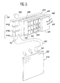
- FIG. 7 schematically represents an alternative embodiment of an excitation module.
- the latter here has a cylindrical shape: the sets of fluorescent fiber sections are arranged side by side so as to form a cylinder bordered therein by a first flat liquid crystal screen 44 itself forming a coaxial cylinder and the cells of which elementary have a strip shape capable of masking a section.
- the cylinder 62 is bordered on the outside by a second flat liquid crystal screen 46, similar to the first, itself forming a coaxial cylinder.
- the artificial light source 58 is arranged in the center of the cylinders; it emits uniformly intense light over the entire cylinder 62. This light is modulated by the liquid crystal screen 44.
- the artificial light source 58 When the ambient light 60 is sufficient to excite the fluorescence of the fluorescent fiber sections, the artificial light source 58 is put out of service. Ambient light 60 is then modulated by the liquid crystal screen 46.
Abstract
Description
La présente invention a pour but objet un dispositif de multiplexage en longueur d'onde utilisant une fibre optique et un écran d'affichage en couleur portant application de ce dispositif. Elle trouve de multiples applications dans des domaines aussi variés que la colorimétrie ou le transport d'informations multiplexé.The object of the present invention is a wavelength multiplexing device using an optical fiber and a color display screen applying this device. It finds multiple applications in fields as varied as colorimetry or the transport of multiplexed information.
Les fibres optiques permettant la propagation guidée d'un signal lumineux, introduit par exemple à l'aide d'une optique de focalisation à travers une extrémité de la fibre, le long de cette fibre vers son autre extrémité.Optical fibers allowing the guided propagation of a light signal, introduced for example using a focusing optic through one end of the fiber, along this fiber towards its other end.
Le coeur de la fibre, réalisé en verre ou en matière plastique transparente, est enrobé dans une gaine transparente d'indice de réfraction plus faible que celui de la matière utilisée pour réaliser le coeur de la fibre, afin que l'interface entre le coeur et cette gaine soit le siège de phénomènes de réflexion totale de la lumière, permettant ainsi la transmission de celle-ci le long de la fibre sans perte notable.The fiber core, made of glass or transparent plastic, is coated in a transparent sheath with a lower refractive index than that of the material used to make the fiber core, so that the interface between the core and this sheath is the seat of phenomena of total reflection of light, thus allowing its transmission along the fiber without significant loss.
Une catégorie particulière de fibres est constituée par les fibres optiques dites "fluorescentes". Le coeur de ces dernières est dopé à l'aide de produits appropriés, de telle sorte que la matière de la fibre, excitée par une irradiation lumineuse, réémet un rayonnement de façon isotrope. Une partie non négligeable de ce rayonnement est piégée au sein de la fibre et se propage par réflexion interne jusqu'aux extrémités de la fibre fluorescente. La fraction du rayonnement capturée est proportionnelle à l'écart Δn entre les indices de réfraction du coeur et de la gaine optique de la fibre. Elle est typiquement de l'ordre de 5 %.A particular category of fibers is made up of so-called "fluorescent" optical fibers. The core of the latter is doped with the aid of suitable products, so that the fiber material, excited by light irradiation, re-emits radiation isotropically. A significant part of this radiation is trapped within the fiber and propagates by internal reflection to the ends of the fluorescent fiber. The fraction of the radiation captured is proportional to the difference Δn between the refractive indices of the core and fiber optic cladding. It is typically around 5%.
Il est possible d'exciter latéralement une telle fibre optique fluorescente évidemment dépourvue de gaine de protection.It is possible to excite laterally such a fluorescent optical fiber obviously without a protective sheath.
De nombreux dispositifs exploitant de telles fibres fluorescentes sont connus et décrits par example dans le document FR-A-2 574 564.Many devices exploiting such fluorescent fibers are known and described for example in document FR-A-2 574 564.
L'invention concerne une application nouvelle de ces fibres fluorescentes excitées latéralement.The invention relates to a new application of these laterally excited fluorescent fibers.
Le transport de signaux en multiplex consiste à injecter simultanément une pluralité de signaux différents dans un dispositif unique destiné à assurer leur acheminement d'un point à un autre. Cette technique permet de diminuer le nombre de dispositifs de transport. Elle est connue depuis longtemps déjà et appliquée à des signaux électriques de télécommunication par example. Le développement récent de télécommunications par fibres optiques pose le problème du transport de signaux optiques en multiplex. On cherche donc à obtenir l'injection simultanée de plusieurs signaux lumineux de couleurs différentes dans une fibre optique unique.Multiplex signal transport consists in simultaneously injecting a plurality of different signals into a single device intended to ensure their routing from one point to another. This technique makes it possible to reduce the number of transport devices. It has been known for a long time and applied to electrical telecommunication signals for example. The recent development of telecommunications by optical fibers poses the problem of the transport of optical signals in multiplex. It is therefore sought to obtain the simultaneous injection of several light signals of different colors into a single optical fiber.
Il n'est malheureusement pas aisé d'introduire simultanément de manière classique un grand nombre de signaux optiques dans une même fibre. En effet, on a vu que l'introduction d'un seul signal nécessite une optique de focalisation et un réglage précis. On conçoit que l'injection simultanée d'un grand nombre de signaux augmente d'autant la difficulté de réglage et la complexité du dispositif.Unfortunately, it is not easy to simultaneously introduce in a conventional manner a large number of optical signals into the same fiber. In fact, we have seen that the introduction of a single signal requires focusing optics and precise adjustment. It is understood that the simultaneous injection of a large number of signals increases the difficulty of adjustment and the complexity of the device.
La présente invention a pour but de pallier ces problèmes d'introduction simultanée de plusieurs signaux optiques dans une fibre. Pour cela on préco nise l'emploi de fibres fluorescentes agencées de manière nouvelle.The present invention aims to overcome these problems of simultaneous introduction of several optical signals into a fiber. For that we preco negates the use of fluorescent fibers arranged in a new way.
De façon plus précise, l'invention concerne un dispositif de multiplexage en longueur d'onde utilisant une fibre optique, caractérisé par le fait qu'il comprend, relié à une première extrémité de cette fibre, un premier ensemble de n tronçons de fibres fluorescentes FM1,...,FMn mis bout à bout, chaque tronçon FMi, i entier allant de 1 à n, étant dopé pour réémettre par fluorescence à une certaine longueur d'onde λMi et étant optiquement couplé à une source lumineuse d'excitation Li, apte à produire la fluorescence, les tronçons FM1,...,FMn étant rangés à partir de l'extrémité de la fibre dans l'ordre croissant de leur longueur de fluorescence respective λM1,...,λMn.More specifically, the invention relates to a wavelength multiplexing device using an optical fiber, characterized in that it comprises, connected to a first end of this fiber, a first set of n sections of fluorescent fibers FM1, ..., FMn placed end to end, each section FMi, i integer ranging from 1 to n, being doped to re-emit by fluorescence at a certain wavelength λMi and being optically coupled to an excitation light source Li , able to produce fluorescence, the sections FM1, ..., FMn being arranged from the end of the fiber in ascending order of their respective fluorescence length λM1, ..., λMn.
Excités latéralement par les sources L1,...,Ln, les tronçons de fibres optiques fluorescentes FM1,...,FMn émettent de manière isotrope une lumière de fluorescence. Une partie de cette lumière est piégée dans les fibres optiques et se propage à l'intérieur de la fibre optique transparente.Laterally excited by the sources L1, ..., Ln, the sections of fluorescent optical fibers FM1, ..., FMn emit isotropically fluorescent light. Part of this light is trapped in the optical fibers and propagates inside the transparent optical fiber.
Selon un mode préféré de réalisation, l'intensité lumineuse de chaque source Li est susceptible d'être modulée. Ainsi, on peut aussi moduler les émissions de lumière de fluorescence des différents tronçons de fibres optiques FM1,...,FMn. Cette modulation peut correspondre par exemple à un signal numérisé. L'invention permet donc le transport d'informations numérisées en multiplex dans la fibre optique transparente par exemple. Le multiplexage est effectué par l'intermédiaire des différentes longueurs d'onde λM1,...,λMn de fluorescence, un signal numérisé étant porté par chaque longueur d'onde λMi.According to a preferred embodiment, the light intensity of each source Li is capable of being modulated. Thus, it is also possible to modulate the fluorescence light emissions of the different sections of optical fibers FM1, ..., FMn. This modulation can correspond for example to a digitized signal. The invention therefore allows the transport of digital information in multiplex in transparent optical fiber for example. Multiplexing is carried out by means of the different wavelengths λM1, ..., λMn of fluorescence, a digitized signal being carried by each wavelength λMi.
Selon une variante de réalisation du dispositif, le premier ensemble de tronçons comporte trois tronçons de fibres optiques FM1, FM2, FM3 : le premier FM1 étant apte à émettre de la lumière de fluorescence bleue, le second FM2 étant apte à émettre de la lumière de fluorescence verte, le troisième FM3 étant apte à émettre de la lumière de fluorescence rouge.According to an alternative embodiment of the device, the first set of sections comprises three sections of optical fibers FM1, FM2, FM3: the first FM1 being able to emit blue fluorescence light, the second FM2 being able to emit light from green fluorescence, the third FM3 being capable of emitting red fluorescence light.
On dispose ainsi d'une source trichrome aux couleurs primaires. La modulation de l'intensité des sources L1, L2, L3 permet de reconstituer à l'extrémité de la fibre transparente un large spectre coloré dû au mélange des trois couleurs primaires (rouge, vert, bleu) dans des proportions variables à volonté.We thus have a trichromatic source in primary colors. The modulation of the intensity of the sources L1, L2, L3 makes it possible to reconstruct at the end of the transparent fiber a wide colored spectrum due to the mixture of the three primary colors (red, green, blue) in variable proportions at will.
Dans une autre variante de réalisation, le dispositif selon l'invention comporte :
- relié à l'autre extrémité de la fibre un second ensemble de n tronçons de fibres optiques fluorescentes FD1,...,FDn mis bout à bout en une succession ordonnée telle que chaque tronçon FDi ne soit excité que par la lumière de fluorescence émise par un seul tronçon de fibre optique FMi du premier ensemble lui correspondant, chaque tronçon FDi émettant à l'extérieur une lumière de fluorescence à la longueur d'onde λDi après excitation, le tronçon FDn produisant la lumière de fluorescence de plus grande longueur d'onde λDn étant relié à cette autre extrémité de la fibre,
- n détecteurs D1,...,Dn aptes à détecter la lumière de fluorescence éventuellement émise latéralement par chacun des n tronçons de fibres optiques FD1,...,FDn respectivement, chacun de ces détecteurs D1,...,Dn délivrant sur des sorties S1,...,Sn, respectivement, un signal électrique correspondant à la lumière détectée,
- un analyseur de signaux électriques ayant n entrées E1,...,En reliées aux sorties S1,...,Sn, respectivement, des détecteurs D1,...,Dn.In another alternative embodiment, the device according to the invention comprises:
- connected to the other end of the fiber a second set of n sections of fluorescent optical fibers FD1, ..., FDn placed end to end in an ordered succession such that each section FDi is only excited by the fluorescent light emitted by a single optical fiber section FMi of the first set corresponding to it, each section FDi emitting outside a fluorescence light at the wavelength λDi after excitation, the section FDn producing the fluorescence light of longer length λDn wave being connected to this other end of the fiber,
- n detectors D1, ..., Dn capable of detecting the fluorescence light possibly emitted laterally by each of the n sections of optical fibers FD1, ..., FDn respectively, each of these detectors D1, ..., Dn delivering on outputs S1, ..., Sn, respectively, an electrical signal corresponding to the detected light,
- an electrical signal analyzer having n inputs E1, ..., En connected to outputs S1, ..., Sn, respectively, detectors D1, ..., Dn.
Selon un aspect secondaire les détecteurs D1,...,Dn présentent un seuil de détection de manière à ne détecter que la lumière de fluorescence provenant des émissions par les tronçons de fibres optiques FD1,...,FDn leur correspondant dûes aux excitations provenant des tronçons FM1,...,FMn du premier ensemble et non la lumière de fluorescence émise par les tronçons FD1,...,FDn dûe à une excitation parasite, cette lumière de fluorescence parasite étant d'intensité très inférieure à la lumière de fluorescence dûe aux excitations provenant des tronçons FM1,...,FMn du premier ensemble.According to a secondary aspect, the detectors D1, ..., Dn have a detection threshold so as to detect only the fluorescence light originating from the emissions by the sections of optical fibers FD1, ..., FDn corresponding to them due to the excitations originating sections FM1, ..., FMn of the first set and not the fluorescence light emitted by the sections FD1, ..., FDn due to parasitic excitation, this parasitic fluorescence light being of much lower intensity than the light of fluorescence due to excitations coming from sections FM1, ..., FMn of the first set.
Cette dernière variante de réalisation, selon l'aspect secondaire, permet d'assurer par exemple, le démultiplexage des informations transportées en multiplex à l'intérieur de la fibre optique transparente. Les différentes lumières de fluorescence modulées provenant du premier ensemble viennent exciter les tronçons de fibres optiques FD1,...,FDn du second ensemble après leur parcours dans la fibre optique transparente. Les tronçons FD1,...,FDn, agencés de manière à n'être excités que par une seule longueur d'onde λM1,...,λMn respectivement, émettent à leur tour des lumières de fluorescence suivant les modulations de chaque source L1,...,Ln respectivement.This last variant, according to the secondary aspect, makes it possible, for example, to demultiplex the information transported in multiplex inside the transparent optical fiber. The different modulated fluorescence lights coming from the first set excite the sections of optical fibers FD1, ..., FDn of the second set after their journey in the transparent optical fiber. The sections FD1, ..., FDn, arranged so as to be excited only by a single wavelength λM1, ..., λMn respectively, in turn emit fluorescence lights according to the modulations of each source L1 , ..., Ln respectively.
Les détecteurs D1,...,Dn placés latéralement en regard des tronçons de fibres optiques FD1,...,FDn délivrent sur leurs sorties S1,...,Sn respectives des signaux électriques analogues aux signaux numérisés modulant les sources L1,...,Ln.The detectors D1, ..., Dn placed laterally opposite the sections of optical fibers FD1, ..., FDn deliver on their respective outputs S1, ..., Sn electrical signals analogous to the digitized signals modulating the sources L1 ,. .., Ln.
L'analyseur permet de reconstituer par exemple des signaux analogiques ; ce peut-être des voix humaines, numérisées pour leur transport par fibre optique, dans une communication de type téléphonique par exemple.The analyzer makes it possible to reconstruct, for example, analog signals; perhaps human voices, digitized for their transport by optical fiber, in a telephone type communication for example.
Une partie de la lumière de fluorescence d'un tronçon de fibre optique peut exciter la fluorescence du tronçon amont. C'est pour éviter de prendre en compte ces émissions parasites d'intensité beaucoup plus faible que l'on fixe un seuil de détection sur la sensibilité des détecteurs D1,...,Dn.Part of the fluorescence light from a section of optical fiber can excite the fluorescence of the upstream section. It is to avoid taking these parasitic emissions of much lower intensity into account that a detection threshold is fixed on the sensitivity of the detectors D1, ..., Dn.
La présente invention concerne aussi un écran d'affichage en couleur comportant plusieurs dispositifs de multiplexage. Les secondes extrémités des fibres optiques de ces dispositifs sont maintenues sensiblement perpendiculaires à une surface déterminée, chacune des extrémités formant un pixel de cet écran.The present invention also relates to a color display screen comprising several multiplexing devices. The second ends of the optical fibers of these devices are kept substantially perpendicular to a determined surface, each of the ends forming a pixel of this screen.
En adoptant la configuration du dispositif de multiplexage où trois tronçons de fibres fluorescentes émettant respectivement des lumières fondamentales bleue, verte et rouge sont reliés à chaque fibre, une modulation adaptée des lumières d'excitation des tronçons permet d'obtenir un pixel en couleur à chaque extrémité de fibre.By adopting the configuration of the multiplexing device where three sections of fluorescent fibers emitting respectively blue, green and red fundamental lights are connected to each fiber, a suitable modulation of the excitation lights of the sections makes it possible to obtain a color pixel at each fiber end.
On peut ainsi multiplier par trois le nombre de pixels par rapport aux écrans connus. En effet, usuellement, une couleur primaire bleu, vert ou rouge est attribuée à chaque pixel monochrome, un pixel en couleur est alors obtenu par la réunion de trois pixels monochromes.We can thus multiply by three the number of pixels compared to known screens. Indeed, usually, a primary blue, green or red color is assigned to each monochrome pixel, a pixel in color is then obtained by the union of three monochrome pixels.
Selon un mode de réalisation préféré, cet écran est composé de modules formant des écrans élémentaires, les modules étant accolés les uns aux autres et étant excités indépendamment les uns des autres par des modules d'excitation auxquels ils sont reliés.According to a preferred embodiment, this screen is composed of modules forming elementary screens, the modules being placed side by side and being excited independently of each other. others by excitation modules to which they are connected.
Selon une variante de ce mode de réalisation, un module d'excitation comprend :
- les ensembles de tronçons de fibres fluorescentes reliés optiquement aux fibres optiques, ces ensembles étant disposés côte à côte, et
- les sources lumineuses d'excitation optiquement couplées aux tronçons,
les sources lumineuses d'excitation étant formées par une source lumineuse principale et les cellules élémentaires d'un écran à cristaux liquides, ces cellules ayant une forme de bande au moins aussi longue et large qu'un tronçon, ces cellules présentant une transparence réglable.According to a variant of this embodiment, an excitation module comprises:
the sets of sections of fluorescent fibers optically connected to the optical fibers, these sets being arranged side by side, and
- the excitation light sources optically coupled to the sections,
the excitation light sources being formed by a main light source and the elementary cells of a liquid crystal screen, these cells having a strip shape at least as long and wide as a section, these cells having an adjustable transparency.
Selon une variante de réalisation de l'écran, la source lumineuse principale est constituée par la lumière ambiante.According to an alternative embodiment of the screen, the main light source is constituted by ambient light.
La source lumineuse principale peut être aussi constituée par une source de lumière artificielle.The main light source can also be constituted by an artificial light source.
Selon un autre mode de réalisation, le module d'excitation présente une forme cylindrique, les ensembles de tronçons de fibre fluorescente étant disposés côte à côte de manière à former un cylindre bordé en son intérieur par un premier écran plat à cristaux liquides formant lui-même un cylindre coaxial et dont les pixels présentent une forme de bande apte à masquer un tronçon, le cylindre formé par les ensembles de tronçons étant bordé en son extérieur par un second écran plat à cristaux liquides semblable au premier et formant lui-même un cylindre coaxial, une source de lumière artificielle étant disposée au centre des cylindres.According to another embodiment, the excitation module has a cylindrical shape, the sets of sections of fluorescent fiber being arranged side by side so as to form a cylinder bordered on its inside by a first flat liquid crystal screen forming itself even a coaxial cylinder, the pixels of which have the shape of a strip capable of masking a section, the cylinder formed by the sets of sections being bordered on its outside by a second flat liquid crystal screen similar to the first and forming itself a coaxial cylinder, an artificial light source being disposed in the center of the cylinders.
D'autres caractéristiques et avantages de l'invention apparaîtront mieux après la description qui suit, donnée à titre explicatif et nullement limitatif. Cette description se réfère à des dessins annexés sur lesquels :
- - la figure 1 représente schématiquement un dispositif selon l'invention,
- - la figure 2 représente schématiquement les spectres d'absorption et de fluorescence du diméthyl-POPOP, colorant utilisable comme dopant d'une fibre optique fluorescente,
- - la figure 3 illustre schématiquement une variante de réalisation d'un dispositif selon l'invention,
- - la figure 4 illustre schématiquement une application de l'invention dans le cas du transport de signaux lumineux en multiplex,
- - la figure 5 représente schématiquement un écran conforme à l'invention et portant application de dispositifs de multiplexage,
- - la figure 6 représente schématiquement un module d'affichage d'un écran conforme à l'invention relié à un module d'excitation,
- - la figure 7 représente schématiquement une variante de réalisation d'un module d'excitation.
- FIG. 1 schematically represents a device according to the invention,
- FIG. 2 schematically represents the absorption and fluorescence spectra of dimethyl-POPOP, a dye usable as a dopant of a fluorescent optical fiber,
- FIG. 3 schematically illustrates an alternative embodiment of a device according to the invention,
- FIG. 4 schematically illustrates an application of the invention in the case of the transport of light signals in multiplex,
- FIG. 5 schematically represents a screen according to the invention and relating to the application of multiplexing devices,
- FIG. 6 schematically represents a display module of a screen according to the invention connected to an excitation module,
- - Figure 7 schematically shows an alternative embodiment of an excitation module.
La figure 1 représente schématiquement un dispositif selon l'invention. Une fibre optique transparente 10 est reliée à un ensemble 12 de n tronçons de fibres optiques fluorescentes FM1,...,FMn. La connexion 14 quasi transparente entre la fibre et l'ensemble de tronçons, est réalisée après polissage des fibres, par des techniques connues de l'homme du métier, au moyen de colle transparente du genre époxy ou cyanoacrylate par exemple. Les connexions 14, 15 reliant différents tronçons entre eux ou un tronçon à la fibre 10 rencontrées dans la suite de la description sont de ce type.FIG. 1 schematically represents a device according to the invention. A transparent
Les différents tronçons de fibres optiques FM1,...,FMn sont dopés chacun avec un colorant organique fluorescent différent.The different sections of optical fibers FM1, ..., FMn are each doped with a different fluorescent organic dye.
La figure 2 représente schématiquement les spectres d'absorption (en trait fort) et de fluorescence (en trait tireté) du diméthyl-POPOP. De tels spectres se retrouvent pour d'autres colorants organiques, aux valeurs des longueurs d'onde près. On constate que les deux spectres sont décalés, l'excitation (absorption) est centrée sur une longueur d'onde de 360 nm environ alors que l'émission de fluorescence s'effectue autour de 415 nm. L'excitation s'effectue à plus haute énergie (à plus petite longueur d'onde) que l'émission de fluorescence. Les pieds des deux spectres se recouvrent partiellement, autour de 400 nm dans le cas du diméthyl-POPOP : un colorant peut donc réabsorber une partie de sa propre émission de fluorescence.FIG. 2 schematically represents the absorption (solid line) and fluorescence (dashed line) spectra of dimethyl-POPOP. Such spectra are found for other organic dyes, except for wavelength values. It can be seen that the two spectra are offset, the excitation (absorption) is centered on a wavelength of approximately 360 nm while the fluorescence emission takes place around 415 nm. The excitation takes place at a higher energy (at a shorter wavelength) than the emission of fluorescence. The feet of the two spectra partially overlap, around 400 nm in the case of dimethyl-POPOP: a dye can therefore reabsorb part of its own fluorescence emission.
Le rendement quantique des colorants fluorescents organiques est excellent de l'ordre de 95 %. Seuls 5 % des photons d'excitation sont perdus en désexcitation non radiative.The quantum yield of organic fluorescent dyes is excellent of the order of 95%. Only 5% of the excitation photons are lost in non-radiative de-excitation.
Les fibres optiques fluorescentes sont des fibres optiques plastiques (F.O.P.) par exemple. Ces dernières présentent de nombreux avantages : elles restent flexibles au diamètre d'utilisation qui est de 1,5 mm par exemple. Ce diamètre important facilite la réalisation des connexions 14. Les F.O.P. se prêtent au dopage par des colorants organiques.Fluorescent optical fibers are plastic optical fibers (FOP) for example. These have many advantages: they remain flexible to the diameter of use which is 1.5mm for example. This large diameter facilitates the making of
Etant donné la large gamme de colorants existants, on peut aisément couvrir tout le spectre visible et même au-delà (le spectre qu'il est possible de couvrir en utilisant différents colorants s'étend de 250 nm à 1000 nm avec des largeurs de bande spectrale pour chaque colorant de l'ordre de 50 nm). Le coeur de la F.O.P. peut être en polystyrène ou en polyméthylmétacrylate (P.M.M.A.) par exemple.Given the wide range of existing dyes, it is easy to cover the entire visible spectrum and even beyond (the spectrum which can be covered using different dyes ranges from 250 nm to 1000 nm with bandwidths spectral for each dye of the order of 50 nm). The heart of the F.O.P. may be made of polystyrene or polymethyl methacrylate (P.M.M.A.) for example.
On voit encore sur la figure 1 que les différents tronçons de fibres optiques FM1,...,FMn sont reliés entre eux par des connexions 15. Les tronçons FM1,...,FMn sont aussi courts que possible : leur longueur est comprise entre 1 et 5 cm par exemple. Cette longueur résulte d'une optimisation calculée en fonction de la concentration du colorant contenu dans le coeur de la F.O.P. Cette concentration est comprise entre 10⁻⁴ et 10⁻³ gramme de colorant par gramme de matériau du coeur. Le choix de la concentration résulte d'un compromis entre la nécessité d'une bonne conversion de la lumière d'excitation (concentration élevée) et d'une faible réabsorption de la lumière de fluorescence par le colorant lui-même dûe au recouvrement des spectres d'absorption et d'émission (concentration faible).It can also be seen in FIG. 1 that the different sections of optical fibers FM1, ..., FMn are interconnected by
L'ensemble 12 est relié à une première extrémité de la fibre optique transparente 12 par le tronçon de fibre optique FM1 émettant la lumière de fluorescence de plus petite longueur d'onde λM1. De plus les différents tronçons de fibres optiques FM1,...,FMn de l'ensemble 12 sont reliés en une succession selon l'ordre croissant de leur longueur d'onde de fluorescence λM1,...,λMm respectivement (du bleu vers le rouge). Autrement dit, dans cet arrangement, la lumière de fluorescence émise par un tronçon de fibre optique FMi et se propageant vers la fibre optique transparente 10 à travers les tronçons de fibres optiques FMi-1,...,FM1 (propagation vers la gauche sur la figure 1) n'est pas absorbée par ces derniers. Les spectres d'absorption et d'émission des colorants ayant une largeur d'environ 50 nm, on doit prendre garde à ce que les différents spectres d'absorption des tronçons de fibres optiques FMi-1,...FM1 ne recouvre pas le spectre d'émission du tronçon de fibre optique FMi. Mais cette condition est aisément respectée si l'on arrange l'ensemble 12 selon l'ordre croissant des longueurs d'onde.The
Les différents tronçons de fibres optiques FM1,...,FMn sont excités par des sources L1,...,Ln respectivement. Les sources L1,...,Ln illuminent latéralement les tronçons de fibres optiques FM1,...,FMn qui sont évidemment dépourvus de gaine de protection mécanique (alors qu'une telle gaine 11 protège la fibre optique 10). Les sources L1,...,Ln peuvent être des diodes électroluminescentes (D.E.L.) dont le rayonnement est convenablement focalisé pour n'exciter qu'un tronçon de fibre optique à la fois.The different sections of optical fibers FM1, ..., FMn are excited by sources L1, ..., Ln respectively. The sources L1, ..., Ln laterally illuminate the sections of optical fibers FM1, ..., FMn which are obviously devoid of mechanical protection sheath (while such a
Les sources L1,...,Ln peuvent aussi être des lampes à large bande spectrale. Si la lumière d'excitation provient de D.E.L. alors les longueurs d'onde d'émission de ces dernières doivent être en accord avec la bande d'absorption des tronçons de fibres optiques en regard.The sources L1, ..., Ln can also be lamps with broad spectral band. If the excitation light comes from D.E.L. then the emission wavelengths of the latter must be in agreement with the absorption band of the facing sections of optical fibers.
Les diverses sources L1,...,Ln sont reliées à un modulateur 16 qui permet de faire varier à volonté l'intensité de la lumière émise par chaque source. Par cet intermédiaire, on peut faire varier l'intensité des lumières de fluorescence.The various sources L1, ..., Ln are connected to a
La figure 3 illustre schématiquement une première variante de réalisation d'un dispositif selon l'invention. Cette variante peut être appliquée à la réalisation d'une source lumineuse servant d'étalon en colorimétrie par exemple. Dans cette variante de réalisation, on n'utilise que trois tronçons de fibres optiques fluorescentes FM1, FM2, FM3 dopés respectivement par du diméthyl-POPOP (émettant de la lumière bleue), par de la Coumarine 520 (émettant de la lumière verte) et de la Rhodamine 6G (émettant de la lumière rouge) par exemple. Ces trois tronçons de fibre optique FM1, FM2, FM3 sont excités par trois sources respectivement, L1, L2, L3 dont l'intensité est modulable grâce au modulateur 16.FIG. 3 schematically illustrates a first alternative embodiment of a device according to the invention. This variant can be applied to the production of a light source serving as a standard in colorimetry for example. In this alternative embodiment, only three sections of fluorescent optical fibers FM1, FM2 and FM3 are used, doped respectively with dimethyl-POPOP (emitting blue light), with Coumarin 520 (emitting green light) and Rhodamine 6G (emitting red light) for example. These three sections of optical fiber FM1, FM2, FM3 are excited by three sources respectively, L1, L2, L3, the intensity of which can be modulated by means of the
Ces trois tronçons FM1, FM2 et FM3 forment l'ensemble 12 relié à une première extrémité de la fibre optique transparente 10. Une excitation simultanée des trois tronçons de fibres optiques FM1, FM2, FM3, mélange les lumières de fluorescence aux couleurs primaires rouge, verte et bleue dans la fibre optique transparente 10. Une émission de lumière blanche est observée à la deuxième extrémité longitudinale de cette dernière. Cette source de lumière en bout de fibre peut servir d'étalon colorimétrique. En faisant varier l'intensité des émissions fluorescentes par l'intermédiaire du modulateur 16, on peut faire varier à volonté la couleur de l'émission en bout de fibre 10. On dispose donc, à partir des trois couleurs fondamentales émises par les tronçons de fibres optiques FM1, FM2, FM3, d'une source de lumière de couleur variable à volonté.These three sections FM1, FM2 and FM3 form the
La figure 4 illustre schématiquement une application de l'invention dans le cas du transport de signaux lumineux en multiplex. Une première extrémité longitudinale de la fibre optique transparente 10 est reliée par une connexion 14 à un premier ensemble de n tronçons de fibres optiques fluorescentes FM1,...,FMn. n sources L1,...,Ln permettent l'excitation latérale des tronçons FM1,...,FMn. L'intensité de la lumière émise par chaque source L1,...,Ln est modulable grâce au modulateur 16. Cette première partie du dispositif est conforme à la description qui a été faite de la figure 1.FIG. 4 schematically illustrates an application of the invention in the case of the transport of light signals in multiplex. A first longitudinal end of the transparent
En vue d'une application au transport multiplexé d'informations, les sources L1,..,Ln sont choisis aptes à être modulées de manière rapide (à une fréquence de l'ordre de la centaine de MHz). Le temps de réponse des colorants à une excitation est de l'ordre de la nanoseconde et ne limite donc pas la bande passante d'un tel système.For an application to the multiplexed transport of information, the sources L1, .., Ln are chosen able to be modulated quickly (at a frequency of the order of a hundred MHz). The response time of the dyes to an excitation is of the order of a nanosecond and therefore does not limit the bandwidth of such a system.
Cette première partie réalise un multiplexage des informations. En effet, si chaque source L1,...,Ln est modulée suivant un signal numérisé, alors chaque tronçon FM1,...,FMn émet une lumière de fluorescence elle aussi modulée suivant le signal numérisé. Le rayonnement de fluorescence des tronçons de fibres optiques FM1,...,FMn est isotrope, mais une partie non négligeable (de l'ordre de 4 à 5 %) est piégée et guidée dans la fibre optique transparente 10. Les différentes lumières de fluorescentre transportent donc simultanément une information sur la même ligne.This first part multiplexes the information. Indeed, if each source L1, ..., Ln is modulated according to a digitized signal, then each section FM1, ..., FMn emits a fluorescence light which is also modulated according to the digitized signal. The fluorescence radiation of the sections of optical fibers FM1, ..., FMn is isotropic, but a non-negligible part (of the order of 4 to 5%) is trapped and guided in the transparent
Ce type de transport de l'information nécessite un dispositif permettant la séparation des différents signaux numérisés. Ce dispositif est réalisé par un second ensemble 18 de tronçons de fibres optiques fluorescentes FD1,...,FDn correspondant respectivement aux tronçons FM1,...,FMn. Ce second ensemble 18 est raccordé par une connexion 17 à la second extrémité longitudinale de la fibre optique transparente 10. La fluorescence de chaque tronçon FDi est apte à être excitée par la lumière de fluorescence du tronçon de fibre optique lui correspondant FMi. Bien entendu, les tronçons FD1,...,FDN du second ensemble 18 sont reliés entre eux, deux à deux, par des connexions 19 en une succession ordonnée telle que chaque tronçon FDi ne soit excité que par la lumière de fluorescence émise par un seul tronçon FMi du premier ensemble 12. Cette condition revient à relier le tronçon FDn produisant la lumière de fluorescence de plus grande longueur d'onde λDn à la fibre optique transparente 10.This type of information transport requires a device allowing the separation of the different digital signals. This device is produced by a second set 18 of sections of fluorescent optical fibers FD1, ..., FDn corresponding respectively to the sections FM1, ..., FMn. This second assembly 18 is connected by a connection 17 to the second longitudinal end of the transparent
Chacun des tronçons de fibres optiques FD1,...,FDn est dépourvu de gaine de protection mécanique et émet une lumière de fluorescence de manière isotrope. Une partie de cette lumière est donc émise latéralement. Des détecteurs D1,...,Dn sont placés latéralement en regard de chacun des tronçons FD1,...,FDn. Ces détecteurs peuvent être du type photodiode au silicium par example. Chaque détecteur Di peut être muni de volets 20 interceptant la lumière provenant des tronçons de fibre optique FDi-1 et FDi+1 adjacents au tronçon de fibre optique FDi.Each of the sections of optical fibers FD1, ..., FDn is devoid of mechanical protection sheath and emits fluorescent light isotropically. Part of this light is therefore emitted laterally. Detectors D1, ..., Dn are placed laterally opposite each of the sections FD1, ..., FDn. These detectors can be of the silicon photodiode type for example. Each detector Di may be provided with flaps 20 intercepting the light coming from the sections of optical fiber FDi-1 and FDi + 1 adjacent to the section of optical fiber FDi.
L'ensemble des tronçons de fibres optiques FD1,...,FDn munis des détecteurs D1,...,Dn correspondants peut-être placé dans un boîtier (non représenté) afin de le protéger des lumières extérieures parasites. Il en est de même pour l'ensemble des tronçons FM1,...,FMn et des sources L1,...,Ln correspondantes.All the sections of optical fibers FD1, ..., FDn provided with the corresponding detectors D1, ..., Dn may be placed in a box (not shown) in order to protect it from extraneous external lights. The same is true for all the sections FM1, ..., FMn and the corresponding sources L1, ..., Ln.
Les détecteurs D1,...,Dn délivrent des signaux électriques correspondant aux signaux optiques détectés sur leurs sorties S1,...,Sn respectives. Un analyseur 22 de signaux électriques est relié par n entrées E1,...,En aux sorties S1,...,Sn des détecteurs D1,...,Dn. Cet analyseur 22 permet de reconstituer des signaux analogiques à partir des signaux numérisés détectés par exemple.The detectors D1, ..., Dn deliver electrical signals corresponding to the optical signals detected on their respective outputs S1, ..., Sn. An electrical signal analyzer 22 is connected by n inputs E1, ..., En to the outputs S1, ..., Sn of the detectors D1, ..., Dn. This analyzer 22 allows analog signals to be reconstructed from the digital signals detected, for example.
Un tronçon de fibre optique FDi du second ensemble 18, comme d'ailleurs un tronçon de fibre optique FMi du premier ensemble 12, émet un rayonnement de fluorescence isotrope. Environ 8 % de ce rayonnement sont piégés dans la fibre optique elle-même : 4 % se propagent dans un sens et 4 % dans l'autre. Etant donné l'arrangement dans lequel sont ordonnés les différents tronçons des premier et second ensembles 12, 18, la lumière de fluorescence peut se propager dans un sens sans être absorbée par les colorants qu'elle rencontre. Dans l'autre sens, par contre, elle peut être absorbée et exciter la fluorescence d'un autre tronçon de fibre optique. Si une source Li excite un tronçon de fibre optique FMi du premier ensemble 12 avec une intensité Io, alors environ 4 % de Io (en supposant le rendement quantique idéalement égal à 100 %) se propageront vers l'extrémité de l'ensemble 12 qui n'est pas reliée à la fibre optique transparente 10 (sens dans lequel il peut y avoir absorption). Si les 4 % de Io (à la longueur d'onde λMi) excitent à leur tour un tronçon FMi+i par exemple, alors ils donneront lieu à une fluorescence de 4 %.(4 %.Io) à la longueur d'onde λMi+1 dans les deux sens de la fibre. Ce phénomène se produit en cascade mais engendre des intensités de plus en plus faibles. Les 4 %.(4 %.Io) à la longueur d'onde λMi+1 après leur propagation à l'intérieur de la fibre optique transparente 10 vont exciter le tronçon de fibre optique FDi+1. Ce tronçon de fibre optique FDi+1 émet donc une première fluorescence à la longeuur d'onde λDi+1 correspondant au signal numérisé sur laquelle se superpose une fluorescence parasite à la même longueur d'onde dûe aux 4%.(4 %.Io).A section of optical fiber FDi of the second set 18, like besides a section of optical fiber FMi of the
D'autre part, un phénomène analogue à la production des 4 %.(4 %.Io) à la longueur d'onde λMi+1 peut se produire dans le second ensemble 18 et ajouter encore une fluorescence parasite à la longueur d'onde λDi+1.On the other hand, a phenomenon analogous to the production of 4%. (4% .Io) at the wavelength λMi + 1 can occur in the second set 18 and still add parasitic fluorescence to the wavelength λDi + 1.
Ces deux types de fluorescences parasites sont, comme on l'a vu, d'intensité beaucoup plus faible que la fluorescence transportant le signal numérisé. Pour qu'elles ne perturbent pas la détection du signal numérisé, il suffit d'imposer un seuil de détection à la sensibilité des détecteurs D1,...,Dn. Ainsi, on peut s'affranchir de ces fluorescences parasites.These two types of parasitic fluorescence are, as we have seen, of much lower intensity than the fluorescence transporting the digitized signal. So that they do not disturb the detection of the digitized signal, it suffices to impose a detection threshold on the sensitivity of the detectors D1, ..., Dn. Thus, one can get rid of these parasitic fluorescences.
A titre d'exemple, on peut citer quatre colorants dopant quatre tronçons de fibres optiques fluorescentes FM1, FM2, FD1, FD2 :

Il est possible d'estimer le rendement en puissance d'un système complet (abstraction faite des pertes minimes de transmission dans la ligne) ; il dépend des paramètres suivants :
- taux de capture de la lumière provenant d'une source : environ 4 %,
- rendement quantique des différents colorants mis en jeu : au moins égal à 95 %,
- pertes de couplage des tronçons de fibres optiques aux connexions : transparence de l'ordre de 80 %,
- taux de capture de la lumière par le détecteur : environ 20 %.It is possible to estimate the power efficiency of a complete system (apart from the minimal transmission losses in the line); it depends on the following parameters:
- rate of capture of light from a source: around 4%,
- quantum yield of the various dyes involved: at least equal to 95%,
- losses of coupling of the sections of optical fibers to the connections: transparency of the order of 80%,
- light capture rate by the detector: around 20%.
Au total, on peut estimer que le rendement du dispositif est de l'ordre de 0,4 %.In total, it can be estimated that the yield of the device is of the order of 0.4%.
La présente invention concerne aussi un écran d'affichage en couleur portant application du dispositif de multiplexage tel que représenté schématiquement sur la figure 3, c'est-à-dire où une fibre optique 10 est reliée à un ensemble de trois tronçons de fibres fluorescentes émettant respectivement une lumière de fluorescence dans l'une des trois couleurs primaires bleu, vert, et rouge.The present invention also relates to a color display screen applying the multiplexing device as shown diagrammatically in FIG. 3, that is to say where an
Un exemple de réalisation d'un tel écran est représenté schématiquement sur la figure 5.An exemplary embodiment of such a screen is shown diagrammatically in FIG. 5.
Les extrémités 32 de plusieurs fibres optiques 10 sont assemblées perpendiculairement à une surface déterminée, un plan dans l'exemple représenté, pour constituer l'écran 30. Chaque extrémité 32 correspond à un pixel de l'écran.The ends 32 of several
La résolution de l'écran peut être extrêmement élevée puisque, avec des fibres jointives, elle est limitée par le diamètre des fibres 10 qui peut être inférieur à 0,1 mm. Les fibres 10 peuvent par exemple être en silice.The resolution of the screen can be extremely high since, with contiguous fibers, it is limited by the diameter of the fibers which can be less than 0.1 mm. The
Les tronçons de fibres fluorescentes auxquels sont reliées les fibres 10 présentent quant à eux un diamètre pouvant aller de 0,5 à 1 mm, un grand diamètre facilitant l'excitation et les connexions.The sections of fluorescent fibers to which the
Un écran large de 2 m et long de 3 m comprend environ 3.10⁶ fibres optiques 10 séparées les unes des autres de 3 mm. Pour permettre sa réalisation, comme on peut le voir sur la figure 5, un tel écran 30 est constitué d'écrans élémentaires ou modules 34 accolés les uns aux autres et excités indépendamment par des modules d'excitation 36 connectés à un circuit de commande 38.A screen 2 m wide and 3 m long comprises approximately 3.10⁶
Comme on le verra plus loin, un module d'excitation 36 comprend les ensembles de tronçons de fibres fluorescentes reliés aux fibres optiques 10 et les sources lumineuses d'excitation correspondantes. La couleur d'un pixel 32 résulte du mélange des trois couleurs primaires (rouge, vert, bleu) en proportion déterminée par l'intensité lumineuse excitant chacun des tronçons fluorescents reliés à la fibre 10 correspondant à ce pixel.As will be seen below, an
Les fibres optiques 10 sont réunies en câbles plats 40 connectés aux modules d'excitation 36. Le brevet français publié sous le n° 2 574 562 décrit un procédé d'ourdissage permettant la réalisation de tels câbles plats constitués de fibres optiques jointives.The
Les modules d'excitation 36 sont commandés par le circuit 38 qui gère l'intensité et la couleur des différents pixels en contrôlant la modulation des sources lumineuses d'excitation.The
La figure 6 représente schématiquement un module d'affichage (écran élémentaire) relié à un module d'excitation.FIG. 6 schematically represents a display module (elementary screen) connected to an excitation module.
Le module d'affichage 34 est constitué par une structure de forme carrée ou rectangulaire par exemple et supportant les extrémités 32 des fibres optiques 10. Ces extrémités 32 peuvent être rangées en lignes ou disposées selon un motif déterminé, carré ou hexagonal par exemple. Une structure peut par exemple supporter 100 000 extrémités 32 de fibres optiques espacées les unes des autres de 3 mm.The
Les fibres optiques sont donc réunies en câbles plats 40 qui assurent la connexion avec le module d'excitation 36. Les fibres optiques 10 sont reliées à des ensembles de tronçons de fibres fluorescentes FM1, FM2, FM3 de manière identique à celle décrite précédemment ; les ensembles sont sensiblement contigüs et disposés selon une rangée 42.The optical fibers are therefore assembled in
Cette rangée 42 est prise en sandwich entre deux écrans plats à cristaux liquides 44 et 46 identiques.This
L'écran 46 est représenté en écorché : on peut voir qu'il comprend un premier support isolant et transparent 48, en verre par exemple, supportant une électrode transparente 50, dont les dimensions déterminent la surface active de l'écran.The
Un second support isolant et transparent, 52 en verre par exemple, supporte des électrodes 54 transparentes, en forme de bande et disposées selon trois lignes.A second insulating and transparent support, 52 made of glass for example, supports
Le cristal liquide 56 est maintenu entre les électrodes 54 et 50. Une cellule élémentaire de l'écran à cristaux liquides est donc formée dans l'intervalle entre une électrode segmentée 54 et l'électrode unique 50. Elle présente donc une forme de bande.The
Le circuit de commande 38 (non représenté sur cette figure) est connecté aux diverses électrodes 50 et 54. Il délivre des tensions de commande et d'adressage convenables et permettant de contrôler l'état de transparence des cellules élémentaires.The control circuit 38 (not shown in this figure) is connected to the
Chacune est positionnée en face d'un tronçon de fibre fluorescente et forme un écran à transparence réglable propre à un tronçon, la largeur et la longueur de la cellule étant au moins égales à celles du tronçon, dont le degré d'excitation est ainsi commandé par la transparence de cet écran.Each is positioned opposite a section of fluorescent fiber and forms a screen with adjustable transparency specific to a section, the width and the length of the cell being at least equal to those of the section, the degree of excitation of which is thus controlled. by the transparency of this screen.
Les sources lumineuses d'excitation couplées aux différents tronçons sont donc composées par les cellules d'un des écrans à cristaux liquides illuminés par une source lumineuse principale : soit la lumière ambiante 60, soit une source de lumière artificielle 58.The excitation light sources coupled to the different sections are therefore composed of the cells of one of the liquid crystal screens illuminated by a main light source: either
L'écran à cristaux liquides 44 est interposé entre la rangée 42 des ensembles de tronçons fluorescents et la source de lumière artificielle 58 qui délivre une lumière apte à exciter la fluorescence des tronçons.The
Par contre, l'écran à cristaux liquides 46 recouvre la rangée 42 des ensembles de tronçons de fibres fluorescentes de manière à masquer la lumière ambiante 60. Lorsque cette dernière est suffisante, la source de lumière artificielle 58 est mise hors service et les tronçons sont excités par la lumière ambiante modulée par l'écran à cristaux liquides 46 commandé par le circuit de commande 38.On the other hand, the
La figure 7 représente schématiquement une variante de réalisation d'un module d'excitation.FIG. 7 schematically represents an alternative embodiment of an excitation module.
Ce dernier présente ici une forme cylindrique : les ensembles de tronçons de fibre fluorescente sont disposés côte à côte de manière à former un cylindre bordé en son intérieur par un premier écran plat à cristaux liquides 44 formant lui-même un cylindre coaxial et dont les cellules élémentaires présentent une forme de bande apte à masquer un tronçon.The latter here has a cylindrical shape: the sets of fluorescent fiber sections are arranged side by side so as to form a cylinder bordered therein by a first flat
Le cylindre 62 est bordé en son extérieur par un second écran plat à cristaux liquides 46, semblable au premier, formant lui-même un cylindre coaxial.The
Dans cette variante de réalisation, la source de lumière artificielle 58 est disposée au centre des cylindres ; elle émet une lumière uniformément intense sur tout le cylindre 62. Cette lumière est modulée par l'écran à cristaux liquides 44.In this alternative embodiment, the artificial
Lorsque la lumière ambiante 60 est suffisante pour exciter la fluorescence des tronçons de fibre fluorescente, la source de lumière artificielle 58 est mise hors service. La lumière ambiante 60 est alors modulée par l'écran à cristaux liquides 46.When the
Claims (11)
- relié à l'autre extrémité de la fibre (10) un second ensemble (18) de n tronçons de fibres optiques fluorescentes FD1,...,FDn mis bout à bout en une succession ordonnée telle que chaque tronçon FDi ne soit excité que par la lumière de fluorescence émise par un seul tronçon de fibre optique FMi du premier ensemble (12) lui correspondant, chaque tronçon FDi émettant une lumière de fluorescence à la longueur d'onde λDi après excitation, le tronçon FDn produisant la lumière de fluorescence de plus grande longueur d'onde λDNn étant relié à cette autre extrémité de la fibre (10),
- n détecteurs D1,...,Dn aptes à détecter la lumière de fluorescence éventuellement émise latéralement par chacun des n tronçons de fibres optiques FD1,...,FDn respectivement, chacun de ces détecteurs D1,...,Dn délivrant sur des sorties S1,...,Sn, respectivement, un signal électrique correspondant à la lumière détectée,
- un analyseur (22) de signaux électriques ayant n entrées E1,...,En reliées aux sorties S1,...,Sn, respectivement, des détecteurs D1,...,Dn.4. Device according to any one of claims 1 and 2, characterized in that it comprises
- connected to the other end of the fiber (10) a second set (18) of n sections of fluorescent optical fibers FD1, ..., FDn placed end to end in an ordered succession such that each section FDi is only excited by fluorescence light emitted by a single stretch of optical fiber FMi of the first set (12) corresponding to it, each section FDi emitting fluorescence light at the wavelength λDi after excitation, the section FDn producing the fluorescence light of longer wavelength λDNn being connected to this other end of the fiber (10),
- n detectors D1, ..., Dn capable of detecting the fluorescence light possibly emitted laterally by each of the n sections of optical fibers FD1, ..., FDn respectively, each of these detectors D1, ..., Dn delivering on outputs S1, ..., Sn, respectively, an electrical signal corresponding to the detected light,
- an analyzer (22) of electrical signals having n inputs E1, ..., En connected to outputs S1, ..., Sn, respectively, detectors D1, ..., Dn.
- les ensembles de tronçons de fibres fluorescentes reliés optiquement aux fibres optiques (10), ces ensembles étant disposés côte à côte, et
- les sources lumineuses d'excitation optiquement couplées aux tronçons,
les sources lumineuses d'excitation étant formées par une source lumineuse principale et les cellules élémentaires d'un écran à cristaux liquides, ces cellules ayant une forme de bande au moins aussi longue et large qu'un tronçon, ces cellules présentant une transparence réglable.8. Screen according to claim 7, characterized in that an excitation module comprises
- the sets of sections of fluorescent fibers optically connected to the optical fibers (10), these sets being arranged side by side, and
- the excitation light sources optically coupled to the sections,
the excitation light sources being formed by a main light source and the elementary cells of a liquid crystal screen, these cells having a strip shape at least as long and wide as a section, these cells having an adjustable transparency.
Applications Claiming Priority (2)
| Application Number | Priority Date | Filing Date | Title |
|---|---|---|---|
| FR8809078A FR2634031A1 (en) | 1988-07-05 | 1988-07-05 | WAVE LENGTH MULTIPLEXING DEVICE USING OPTICAL FIBER |
| FR8809078 | 1988-07-05 |
Publications (2)
| Publication Number | Publication Date |
|---|---|
| EP0351284A2 true EP0351284A2 (en) | 1990-01-17 |
| EP0351284A3 EP0351284A3 (en) | 1990-07-04 |
Family
ID=9368081
Family Applications (1)
| Application Number | Title | Priority Date | Filing Date |
|---|---|---|---|
| EP89401903A Withdrawn EP0351284A3 (en) | 1988-07-05 | 1989-07-03 | Wavelength division multiplexer utilizing an optical fibre and colour display as application of the same |
Country Status (2)
| Country | Link |
|---|---|
| EP (1) | EP0351284A3 (en) |
| FR (1) | FR2634031A1 (en) |
Cited By (1)
| Publication number | Priority date | Publication date | Assignee | Title |
|---|---|---|---|---|
| EP0489155A1 (en) * | 1990-06-25 | 1992-06-10 | LEE, Ho-Shang | Fiber optic lamp |
Citations (10)
| Publication number | Priority date | Publication date | Assignee | Title |
|---|---|---|---|---|
| US3909823A (en) * | 1974-03-26 | 1975-09-30 | Keith L Knowlton | An optical fiber variable display system utilizing a single light source |
| FR2325946A1 (en) * | 1975-09-24 | 1977-04-22 | Siemens Ag | Indicator waveguide reflecting guided waves at specified points - has scatter centres in wave-guiding material and cover surface through which waves are propagated |
| GB2043979A (en) * | 1979-03-12 | 1980-10-08 | Timex Corp | Backlight for electrooptic display devicee |
| EP0049048A1 (en) * | 1980-09-02 | 1982-04-07 | Xerox Corporation | Fluorescent activated, spatially quantitative light detector |
| DE3247659A1 (en) * | 1982-12-23 | 1984-06-28 | Wolfgang Dr. 7000 Stuttgart Ruhrmann | OPTICAL SENSOR |
| FR2573230A1 (en) * | 1984-11-13 | 1986-05-16 | Garnier Francis | Transmitter sensor and flat screen electro-optical display and the optical fibres for their implementation |
| FR2574564A1 (en) * | 1984-12-10 | 1986-06-13 | Commissariat Energie Atomique | METHOD FOR OPERATING LIGHT RADIATION USING FLUORESCENT OPTICAL FIBERS, AND DEVICES AND FUNCTIONAL APPARATUS USING THE SAME |
| FR2579808A1 (en) * | 1985-03-29 | 1986-10-03 | Rioual Patrick | Optical fibre and liquid crystal colour display device |
| US4618211A (en) * | 1984-03-12 | 1986-10-21 | At&T Bell Laboratories | Optical fiber tap with activatable chemical species |
| EP0249746A2 (en) * | 1986-06-12 | 1987-12-23 | Messerschmitt-Bölkow-Blohm Gesellschaft mit beschränkter Haftung | Optical fibre for a databus system |
-
1988
- 1988-07-05 FR FR8809078A patent/FR2634031A1/en active Pending
-
1989
- 1989-07-03 EP EP89401903A patent/EP0351284A3/en not_active Withdrawn
Patent Citations (11)
| Publication number | Priority date | Publication date | Assignee | Title |
|---|---|---|---|---|
| US3909823A (en) * | 1974-03-26 | 1975-09-30 | Keith L Knowlton | An optical fiber variable display system utilizing a single light source |
| FR2325946A1 (en) * | 1975-09-24 | 1977-04-22 | Siemens Ag | Indicator waveguide reflecting guided waves at specified points - has scatter centres in wave-guiding material and cover surface through which waves are propagated |
| GB2043979A (en) * | 1979-03-12 | 1980-10-08 | Timex Corp | Backlight for electrooptic display devicee |
| EP0049048A1 (en) * | 1980-09-02 | 1982-04-07 | Xerox Corporation | Fluorescent activated, spatially quantitative light detector |
| DE3247659A1 (en) * | 1982-12-23 | 1984-06-28 | Wolfgang Dr. 7000 Stuttgart Ruhrmann | OPTICAL SENSOR |
| US4618211A (en) * | 1984-03-12 | 1986-10-21 | At&T Bell Laboratories | Optical fiber tap with activatable chemical species |
| FR2573230A1 (en) * | 1984-11-13 | 1986-05-16 | Garnier Francis | Transmitter sensor and flat screen electro-optical display and the optical fibres for their implementation |
| FR2574564A1 (en) * | 1984-12-10 | 1986-06-13 | Commissariat Energie Atomique | METHOD FOR OPERATING LIGHT RADIATION USING FLUORESCENT OPTICAL FIBERS, AND DEVICES AND FUNCTIONAL APPARATUS USING THE SAME |
| US4753512A (en) * | 1984-12-10 | 1988-06-28 | Commissariat A L'energie Atomique | Process for utilizing light radiation with the aid of fluorescent optical fibres and functional devices and apparatus using said process |
| FR2579808A1 (en) * | 1985-03-29 | 1986-10-03 | Rioual Patrick | Optical fibre and liquid crystal colour display device |
| EP0249746A2 (en) * | 1986-06-12 | 1987-12-23 | Messerschmitt-Bölkow-Blohm Gesellschaft mit beschränkter Haftung | Optical fibre for a databus system |
Cited By (2)
| Publication number | Priority date | Publication date | Assignee | Title |
|---|---|---|---|---|
| EP0489155A1 (en) * | 1990-06-25 | 1992-06-10 | LEE, Ho-Shang | Fiber optic lamp |
| EP0489155A4 (en) * | 1990-06-25 | 1993-01-07 | Ho-Shang Lee | Fiber optic lamp |
Also Published As
| Publication number | Publication date |
|---|---|
| EP0351284A3 (en) | 1990-07-04 |
| FR2634031A1 (en) | 1990-01-12 |
Similar Documents
| Publication | Publication Date | Title |
|---|---|---|
| EP0567385B1 (en) | Image acquisition device for an object | |
| EP0751740A1 (en) | Endoscopic or fiberoptic imaging device using infrared fluorescence | |
| WO2006034943A1 (en) | Illuminated light box with light-emitting diodes | |
| EP3207541B1 (en) | Polarising photovoltaic module built into the screen of an electronic display device | |
| FR2722305A1 (en) | LIQUID CRYSTAL DISPLAY LIGHTING DEVICE AND MANUFACTURING METHOD THEREOF | |
| WO2015162343A1 (en) | Display device with integrated photovoltaic cells with improved brightness and reflectivity | |
| FR2655430A1 (en) | OPTICAL CUTTER AND COMPUTER SYSTEM WITH DISTRIBUTED PROCESSORS. | |
| EP0351284A2 (en) | Wavelength division multiplexer utilizing an optical fibre and colour display as application of the same | |
| EP0187561A1 (en) | Method of exploiting light radiation using fluorescent optical fibres, and devices or apparatuses using the same | |
| EP0050555B1 (en) | Devices for coupling light between optical fibres | |
| FR2691579A1 (en) | System for converting an infrared image into a visible or near infrared image. | |
| FR2737789A1 (en) | REAR LIGHTING SYSTEM FOR TRANSMISSIVE ELECTRO-OPTICAL MODULATOR AND DISPLAY DEVICE COMPRISING SUCH A LIGHTING SYSTEM | |
| EP0937273B1 (en) | Compact lighting device | |
| FR2609778A1 (en) | COLD LIGHT SOURCE WITH HIGH LUMINANCE AND USE FOR IMAGE VISUALIZATION DEVICE | |
| FR2601146A1 (en) | OPTICAL ADDRESSING DEVICE AND ITS USE IN ELECTROOPTIC IMAGING DEVICES | |
| WO2006013163A1 (en) | Illuminating source for liquid crystal display | |
| FR3097935A1 (en) | Lighting and / or signaling device | |
| FR3107124A1 (en) | Apparatus for observing a star | |
| BE1016311A3 (en) | Illumination device of a vehicle wheel. | |
| EP1611467A1 (en) | Optical system based on optical fibers with sloping grating | |
| FR2619937A1 (en) | Two-dimensional optical modulator | |
| FR2858705A1 (en) | Light panel for e.g. flat television screen, has active matrix located opposite to plane face of plate, and light source directing portions of light beam portions towards plates sectional face and contact plate, respectively | |
| EP0524878A1 (en) | Microwave semiconductor absorber with optical command | |
| EP1550901A1 (en) | Optical power equalization device and corresponding system | |
| FR2759468A1 (en) | HOLOGRAPHIC DEVICE FOR FORMING LIGHT BEAMS OF PREDETERMINED SPECTRAL COMPOSITIONS AND VIDEO IMAGE PROJECTOR COMPRISING SUCH A DEVICE |
Legal Events
| Date | Code | Title | Description |
|---|---|---|---|
| PUAI | Public reference made under article 153(3) epc to a published international application that has entered the european phase |
Free format text: ORIGINAL CODE: 0009012 |
|
| AK | Designated contracting states |
Kind code of ref document: A2 Designated state(s): DE FR GB IT SE |
|
| PUAL | Search report despatched |
Free format text: ORIGINAL CODE: 0009013 |
|
| RHK1 | Main classification (correction) |
Ipc: G09F 9/30 |
|
| AK | Designated contracting states |
Kind code of ref document: A3 Designated state(s): DE FR GB IT SE |
|
| 17P | Request for examination filed |
Effective date: 19901208 |
|
| STAA | Information on the status of an ep patent application or granted ep patent |
Free format text: STATUS: THE APPLICATION IS DEEMED TO BE WITHDRAWN |
|
| 18D | Application deemed to be withdrawn |
Effective date: 19930201 |