EP0358512A2 - Position detecting method and apparatus - Google Patents
Position detecting method and apparatus Download PDFInfo
- Publication number
- EP0358512A2 EP0358512A2 EP89309095A EP89309095A EP0358512A2 EP 0358512 A2 EP0358512 A2 EP 0358512A2 EP 89309095 A EP89309095 A EP 89309095A EP 89309095 A EP89309095 A EP 89309095A EP 0358512 A2 EP0358512 A2 EP 0358512A2
- Authority
- EP
- European Patent Office
- Prior art keywords
- objects
- light
- interval
- positional relationship
- detecting
- Prior art date
- Legal status (The legal status is an assumption and is not a legal conclusion. Google has not performed a legal analysis and makes no representation as to the accuracy of the status listed.)
- Granted
Links
Images


Classifications
-
- G—PHYSICS
- G03—PHOTOGRAPHY; CINEMATOGRAPHY; ANALOGOUS TECHNIQUES USING WAVES OTHER THAN OPTICAL WAVES; ELECTROGRAPHY; HOLOGRAPHY
- G03F—PHOTOMECHANICAL PRODUCTION OF TEXTURED OR PATTERNED SURFACES, e.g. FOR PRINTING, FOR PROCESSING OF SEMICONDUCTOR DEVICES; MATERIALS THEREFOR; ORIGINALS THEREFOR; APPARATUS SPECIALLY ADAPTED THEREFOR
- G03F9/00—Registration or positioning of originals, masks, frames, photographic sheets or textured or patterned surfaces, e.g. automatically
- G03F9/70—Registration or positioning of originals, masks, frames, photographic sheets or textured or patterned surfaces, e.g. automatically for microlithography
- G03F9/7049—Technique, e.g. interferometric
Definitions
- This invention relates generally to a position detecting method and apparatus suitably usable, for example, in a semiconductor microcircuit device manufacturing exposure apparatus for lithographically transferring a fine electronic circuit pattern formed on the surface of a first object (original) such as a mask or reticle (hereinafter simply "mask") onto the surface of a second object (workpiece) such as a wafer, for relatively positioning or aligning the mask and the wafer.
- a first object original
- a mask or reticle hereinafter simply "mask”
- the relative alignment of a mask and a wafer is one important factor in respect to ensuring improved performance.
- alignment systems employed in recent exposure apparatuses submicron alignment accuracies or more strict accuracies are required in consideration of the demand for higher degree of integration of semiconductor devices.
- alignment patterns are provided on a mask and a wafer and, by utilizing positional information obtainable from these patterns, the mask and wafer are aligned.
- the manner of executing the alignment as an example there is a method wherein the amount of relative deviation of these alignment patterns is detected on the basis of image processing.
- Another method is proposed in U.S. Patent Nos. 4,037,969 and 4,326,805 and Japanese Laid-Open Patent Application, Laid-Open No. Sho 56-157033, wherein so-called zone plates are used as alignment patterns upon which light is projected and wherein the positions of light spots formed on a predetermined plane by lights from the illuminated zone plates are detected.
- an alignment method utilizing a zone plate is relatively insensitive to any defect of an alignment pattern and therefore assures relatively high alignment accuracies, as compared with an alignment method simply using a traditional alignment pattern.
- Figures 1A and 1B are schematic views of a known type alignment system utilizing zone plates.
- a light emanating from a light source 100 passes through an optical system 102 and a half mirror 108 and is transformed by a lens 110 into a parallel light. Thereafter, the light illuminates mask alignment patterns 12 and 20 on a mask 10 and a wafer alignment pattern 61 on a wafer 60 which is placed on a support table 84.
- Each of these alignment patterns 12, 20 and 61 is provided by a reflection type zone plate and functions to form a spot of focused light on a plane 92. The amount of relative deviation of the positions of these light spots formed on the plane 92 is detected through the condensing lens 110 and a lens 116.
- the wafer support table 84 is driven to relatively align the mask 10 and the wafer 60.
- Figure 1B is an explanatory view, illustrating the relationship of lights from the mask alignment patterns 12 and 20 and the wafer alignment pattern 61, shown in Figure 1A.
- each inputted light 88 or 90 is diffracted by the mask alignment pattern 12 or 20 and forms a spot of focused light in the neighborhood of the plane 92.
- Another portion of the light passes through the mask 10 in the form of a zero-th order transmission light and is collected in the neighborhood of the plane 92, to form a spot of focused light representing the wafer position.
- the mask 10 when the light diffracted by the wafer 60 forms a spot, the mask 10 functions merely as a transparent member.
- each spot of focused light as formed by the wafer alignment pattern 61 or 62 in the described manner can shift along the plane 92, in accordance with the amount of deviation of the wafer 60 relative to the mask 10.
- the gap or interval g between the mask and the wafer contains an indeterminate value of a certain amount and, from which the following inconveniences arise:
- the state of alignment of a mask and a wafer can be detected at any one of the sites of light spots 78a and 78b. Since, however, a deviation ⁇ ′ of each light spot is dependent on both of the deviation ⁇ of the mask and the wafer and the gap g therebetween, it is possible that many pairs of deviations ⁇ and gaps g do correspond to a single deviation ⁇ ′. This results in that, in a case where the state of alignment is to be detected at the site of the light spot 78a and if, when the correct spacing g is not attained, the light is concentrated at the site of the spot 78b, then the exact measurement of the amount of deviation ⁇ ′ can not determine the deviation ⁇ exactly. For this reason, a single alignment operation which is normally sufficient is insufficient and two or more operations must be done repeatedly, resulting in reduction in throughput.
- the exact measurement of the amount of deviation ⁇ ′ does not always make the amount of deviation ⁇ equal to zero, resulting in incorrect discrimination of the state of alignment.
- the interval should be set at least at a lowest precision of an order not more than 0.01 micron.
- the conventional method it is difficult to accomplish this. Additionally, any attempts to enhancement in the precision would make the whole structure of the apparatus quite complicated.
- Figure 3 is a schematic representation of a major portion of a first embodiment of the present invention
- Figure 4 is a schematic representation wherein paths of lights are illustrated in an unfolded view.
- a light flux l 1 emanates from a light source LS which may comprise a semiconductor laser or LED, for example.
- the light l 1 is incident on physical optic elements Z1, Z2 and Z3 provided on a first object such as a mask, with an angle of incidence of ⁇ . Details of the physical optic elements will be described later.
- Denoted at 2 is a second object such as a wafer, for example, which is disposed opposed to the first object 1 with an interval or gap g maintained therebetween.
- Numeral 3 denotes the position on the first object at which the light reflected (diffracted) by the second object impinges again on the first object.
- Character ⁇ denotes the amount of relative positional deviation of the first object 1 and the second object 2.
- the first object is provided with physical optic elements Z1, Z2, Z3 and Z6 each of which is of a transmission type.
- the light l 1 is projected on the physical optic elements Z1, Z2 and Z3.
- the second object 2 is provided with reflection type physical optic elements Z4 and Z5, although they are illustrated in Figure 4 as being transmission type, for convenience.
- Each of these physical optic elements Z1 - Z6 may be provided by a diffraction grating or a zone plate, for example.
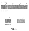
- Figure 5 illustrates examples of patterns of physical optic elements to be provided on the first and second objects 1 and 2, in this embodiment.
- the physical optic element Z3 has a lens function having a focal point F1 and a focal length f1.
- the physical optic element Z4 is arranged to produce constantly a diffraction light in a predetermined direction, independently of the amount of positional deviation.
- Each of characters l 2 - l 7 denotes diffraction light of a predetermined order or orders, from corresponding one of the physical optic elements.
- Denoted at 4 is a sensor which may comprise a line sensor or an area sensor, for example, and the sensor is disposed at a distance L from the first object 1.
- Denoted at a1, a2 and a3 are optical axes of the physical optic element Z1, Z2 and Z3, respectively.
- the optical axes a1 and a2 are spaced by a distance D1, while the optical axes a2 and a3 are spaced by a distance D2.
- Points C1, C2 and C3 each denotes the center of gravity of corresponding diffraction light l 4, l 5 or l 7, upon the sensor 4 surface.
- the point C1 is at a distance y0 from the optical axis a1
- the point C3 is at a distance y1 from the optical axis a3.
- center of gravity of light means such a point that, when in the cross-section of the light a position vector of each point in the section is multiplied by the light intensity of that point and the thus obtained products are integrated over the entire section, the integrated value has a "zero vector”.
- Signal processing circuit 5 is arranged to detect the center of gravity of each light l 4, l 5 or l 7 from the information supplied by the sensor 4, and also to detect any positional deviation ⁇ and the interval g between the first and second objects 1 and 2, on the basis of the distances y1, y0, D1, D2 and the like and by using equations which will be described later.
- Control circuit 6 is operable in accordance with the information concerning the positional deviation ⁇ and the gap g, as supplied from the signal processing circuit 5, to control the deviation ⁇ and the gap g between the first and second objects 1 and 2.
- Stage controller 7 is operable in response to instructions from the control circuit 6, to drive a stage (not shown) on which the second object 2 is placed.
- the light l 1 from the light source is projected on each of the physical optic elements Z1, Z2 and Z3 which are provided on the first object 1.
- the physical optic elements Z1 produces first order diffraction light l 2 which is in the form of a convergent beam.
- the diffraction light l 2 enters the physical optic element Z4 on the second object 2, whereby first order diffraction light l 3 having a chief ray extending with an angle ⁇ 0 with respect to the optical axis a1 is produced.
- first order diffraction light l 4 having a chief ray extending in parallel to the optical axis a1 is produced.
- the diffraction light l 4 is focused on the sensor 4 surface, at a position spaced by a distance y0 from the optical axis a1.
- the physical optic elements Z4 and Z6 are arranged to produce diffraction lights having their chief rays extending with an angle ⁇ 0 and in parallel to the optical axis a1, respectively, independently of the positional deviation ⁇ (i.e. independently of the position of incidence of light thereupon). Therefore, the distance y0 is independent of the positional deviation ⁇ .
- the distance y0 is so small that the measurement thereof is difficult, enlargement by using a lens system, for example, may be adopted.
- the optical path for the lights l 1 - l4 serves to provide a detection system A.
- the physical optic element Z3 has a convex lens function having a focal point F1 and a focal length f1. A portion of the light l 1 incident on the physical optic element Z3 is transformed into first order diffraction light l 6 in the form of a convergent beam and enters the physical optic element Z5.
- the physical optic element Z5 has a concave lens function and, by this function, first order diffraction light l 7 whose direction of diffraction is changeable with the positional deviation ⁇ , is produced. The diffraction light l 7 simply passes through the physical optic element Z3, as zero-th order diffraction light.
- the diffraction light l 7 is focused at a position on the sensor 4 surface, spaced by a distance y1 from the optical axis a3. Since the distance between the sensor 4 and the first object 1 is maintained at a constant value L, the magnitude of the distance y1 is dependent upon the gap g and the positional deviation ⁇ .
- the optical path for the lights l 1, l 6 and l 7 serves to provide a detection system C.
- first order diffraction light l 5 which is in the form of a convergent beam is reflected by the second object 2 (although, for convenience, it is illustrated in Figure 4 as being transmitted), and goes along the optical axis a2 to the sensor 4.
- the point C2 of the center of gravity of the light l 5 is constantly on the optical axis a2, independently of the positional deviation ⁇ and the gap g.
- the point C2 provides a positional reference for the gravity centers C1 and C3 of the other lights on the sensor 4 surface.
- the optical path for the lights l 1 - l 5 serves to provide a detection system B.
- the signal processing circuit 5 operates first to detect the positions C1, C2 and C3 of the respective gravity centers of lights l 4, l 5 and l 7, from the data as collected by the sensor 4. Thereafter, the signal processing circuit 5 operates to calculate the interval d1 between the points C1 and C2 and the interval d2 between the points C2 and C3. Subsequently, the signal processing circuit operates to detect the distances y0 and y1, by using the values of distances D1 and D2 which are predetermined, and in accordance with the following equation:
- the positional deviation ⁇ and the gap g are detected.
- control circuit 6 operates to actuate the stage controller 7 to move the second object 2 to a predetermined position.
- usable diffraction light is not limited to first order diffraction light. Substantially the same advantageous effects are attainable by use of higher-order diffraction light, such as second order or an order higher than it.
- the components such as a high source and a sensor can be collectively disposed at one site. Therefore, an optical probe of small size structure is attainable. Additionally, since there is no necessity of moving the optical probe at the time of exposure, it is possible to increase the throughput.
- the light l 1 passes through the physical optic elements Z3 and Z5, each having a lens function, and is projected upon the point C3.
- Figure 6 is a schematic representation similar to Figure 4, but shows a major portion of a second embodiment of the present invention.
- the device includes detection systems B and C having substantially the same functions as of the detection systems B and C shown in Figure 3.
- Physical optic element Z7 has a concave lens function having a focal point F2 and a focal length f2 and, as a light flux l 1 is projected on the physical optic element Z7, the element Z7 produces first order diffraction light l 8 which is in the form of a divergent beam.
- the diffraction light l 8 enters another physical optic element Z8 having a convex lens function, whereby first order diffraction light l 9 whose direction of diffraction is changeable with a positional deviation ⁇ is produced.
- the diffraction light l 9 is focused at a position spaced from the optical axis by a distance y2. The amount of distance y2 at this time is dependent upon the deviation ⁇ and the interval g.
- the optical path for the lights l 1, l 8 and l 9 serves to provide a detection system D.
- the deviation ⁇ and the interval g can be detected from two relations, such as follows, which are concerned with the deviation ⁇ and the interval g:
- ⁇ :y2 (f2+g) : (f2+g+L+g)
- ⁇ y2 (L+2g+f2)/(f2+g) ⁇ (7)
- the center of gravity of the light spot formed by a zero-th order diffraction light component l 10 of the light l 6 is always coincident with the optical axis a3, regardless of any shift of the position of the second object 2, it may be used in place of the detection system B. In that occasion, the point C5 provides a reference position. Such an embodiment will be explained below.
- Figure 7 is a schematic representation of a major portion of a third embodiment of the present invention. While in this embodiment flight flux l 1 is incident on the first object 1 with an angle ⁇ , basic operation of this embodiment is substantially the same as that of the second embodiment shown in Figure 6.
- One important feature of the present embodiment resides in that as a reference position the center of gravity of light l 10 impinging on the point C5 is detected. Detection of the point C5 leads to that, when the deviation between the first and second objects 1 and 2 comes to zero, i.e., when they are aligned, the center of gravity of light at C3 and the center of gravity of light at C5 coincide with each other.
- the physical optic elements Z3, Z7, Z5 and Z8 are arranged so that, when the first and second objects are in alignment with each other, the optical axes of the elements Z3 and Z7 and the optical axes of the elements Z5 and Z8 are mutually deviated by ⁇ 1 and ⁇ 2, respectively. This avoids overlapping of the gravity centers when correct alignment of the objects is established.
- Figure 8 shows examples of patterns which can be used as the physical optic elements Z3, Z7, Z5 and Z8 provided on the first and second objects 1 and 2 of the present embodiment.
- character ⁇ 1 denotes the amount of deviation between the optical axes of the physical optic elements Z3 and Z5, while character ⁇ 2 denotes the amount of deviation between the optical axes of the physical optic elements Z7 and Z8.
- Figure 9 is a schematic representation similar to Figure 4, but shows a major portion of a fourth embodiment of the present invention.
- physical optic element Z9 has a concave lens function having a focal point F3 and a focal length f3
- physical optic element Z10 has a convex lens function having a focal point F4 and a focal length f4.
- additional physical optic elements Z11 and Z12 having a convex lens function and a concave lens function, respectively.
- each of the physical optic elements Z9 and Z10 provided on the first object 1 has an eccentricity by which the focal point position is deviated by ⁇ 3 or ⁇ 4 from a normal to the physical optic element.
- first order diffraction lights l 12 and l 14 When, in this embodiment, the light l 1 is incident on the physical optic elements Z9 and Z10, there are produced first order diffraction lights l 12 and l 14.
- the lights l 12 and l 14 are projected on the physical optic elements Z11 and Z12 and, in response, there are produced first order diffraction lights l 13 and l 15 which are focused at points spaced by distances y3 and y4, respectively, from the optical axes a5 and a6, respectively.
- the point C2 of the center of gravity of light in the detection system B provides, like the detection system B shown in Figure 4, a reference for the other positions.
- the optical axis of the detection system B is positioned intermediate of the optical axes of the other two detection systems. It may be positioned anywhere.
- Figure 10 is a schematic representation similar to Figure 4, but shows a major portion of a fifth embodiment of the present invention.
- Physical optic elements Z13 and Z14 are provided and they have a convex lens function and a concave lens function, respectively.
- the interval g between the first and second objects 1 and 2 is not correct and, as a result, a light spot image on the sensor surface is shifted or defocused.
- any change in the interval g causes a change in the half width ⁇ of the light spot on the sensor.
- the size (expansion) of a signal light spot on the sensor increases both when the mask-to-wafer interval is larger than the predetermined interval g0 and when the mask-to-wafer interval is smaller than g0.
- the effective pattern area size of the physical optic element Z14 reduces in relative by (S- ⁇ )/S and, therefore, substantially in inverse proportion to this the size of the spot on the sensor increases (provided that S » ⁇ ).
- the present embodiment is a special case where two equations are obtained from one detection system.
- the change in the half width of light per unit length in the direction of the optical axis is larger. Therefore, the change in the half width with the change in the interval g can be detected with a good sensitivity. Namely, the depth of focus of the lens system becomes short and, as a result, the change in the half width ⁇ can be detected with a good sensitivity.
- FIG 11 is a schematic representation of a major portion of a sixth embodiment of the present invention.
- This embodiment corresponds to a modified form of the detection system A shown in Figure 4, wherein the distance y0 is replaced by a quantity y6 which is dependent only upon the interval g between the first and second objects 1 and 2.
- a relation y6 F A (g)
- first order diffraction light l 18 which is in the form of a convergent beam.
- first order diffraction light l 20 with the chief ray being deflected in a direction of an angle ⁇ 6, is produced.
- the zero-th order diffraction light component of the diffraction light l 18 impinges on a physical optic element Z17 which is provided on the first object and which has only a light deflecting function, in response to which impingement there is produced first order diffraction light l 21 whose chief ray being deflected in a direction of an angle ⁇ 6.
- These diffraction lights l 20 and l 21 are focused at points C10 and C11, respectively, on the sensor 4 surface.
- the optical path for the lights l 1 to l 20 or l 21 serves to provide a detection system G.
- the remaining portion of this embodiment is substantially the same as the corresponding portion of the Figure 4 embodiment and, like the first embodiment, the values of g and ⁇ can be detected.
- any positional deviation ⁇ between the first and second objects as well as the interval g between the first and second objects are detected. This avoids incorrect discrimination of the state of alignment between these objects. Also, it is possible to correct the detected deviation ⁇ by using the value of the interval g. As a result, it is possible to provide an alignment system having high alignment precision and attaining high throughput.
- the alignment is to be made by using the detecting system C of the alignment system of the present invention
- g 30 microns
- f1 100 microns
- L 18000 microns
- y1 300 microns
- the alignment with a precision of 0.01 micron it is necessary to suppress the error in the interval g to 0.3 micron or less.
- the positional deviation ⁇ and the interval g can be measured at the same time and the error in the interval g can be reduced to 0.3 micron or less. As a result, an alignment precision of 0.01 micron is attainable.
- physical optic element means is used both for the detection of the positional deviation ⁇ and for the detection of the interval g. This reduces the number of required physical optic elements or lights, thus making the detection system simple and reducing in size of the apparatus as a whole.
- quantities on a sensor such as the distances y1 and y2 can be detected each in terms of a difference between two values. It is therefore possible to cancel any error which might be caused by inclination of the second object 2 in the alignment direction. As a result, more accurate alignment is assured.
Abstract
Description
- This invention relates generally to a position detecting method and apparatus suitably usable, for example, in a semiconductor microcircuit device manufacturing exposure apparatus for lithographically transferring a fine electronic circuit pattern formed on the surface of a first object (original) such as a mask or reticle (hereinafter simply "mask") onto the surface of a second object (workpiece) such as a wafer, for relatively positioning or aligning the mask and the wafer.
- In exposure apparatuses for use in the manufacture of semiconductor devices, the relative alignment of a mask and a wafer is one important factor in respect to ensuring improved performance. Particularly, as for alignment systems employed in recent exposure apparatuses, submicron alignment accuracies or more strict accuracies are required in consideration of the demand for higher degree of integration of semiconductor devices.
- In many types of alignment systems, features called "alignment patterns" are provided on a mask and a wafer and, by utilizing positional information obtainable from these patterns, the mask and wafer are aligned. As for the manner of executing the alignment, as an example there is a method wherein the amount of relative deviation of these alignment patterns is detected on the basis of image processing. Another method is proposed in U.S. Patent Nos. 4,037,969 and 4,326,805 and Japanese Laid-Open Patent Application, Laid-Open No. Sho 56-157033, wherein so-called zone plates are used as alignment patterns upon which light is projected and wherein the positions of light spots formed on a predetermined plane by lights from the illuminated zone plates are detected.
- Generally, an alignment method utilizing a zone plate is relatively insensitive to any defect of an alignment pattern and therefore assures relatively high alignment accuracies, as compared with an alignment method simply using a traditional alignment pattern.
- Figures 1A and 1B are schematic views of a known type alignment system utilizing zone plates.
- In Figures 1A and 1B, a light emanating from a
light source 100 passes through anoptical system 102 and ahalf mirror 108 and is transformed by alens 110 into a parallel light. Thereafter, the light illuminatesmask alignment patterns mask 10 and awafer alignment pattern 61 on awafer 60 which is placed on a support table 84. Each of thesealignment patterns plane 92. The amount of relative deviation of the positions of these light spots formed on theplane 92 is detected through thecondensing lens 110 and alens 116. - In accordance with the detection, the wafer support table 84 is driven to relatively align the
mask 10 and thewafer 60. - Figure 1B is an explanatory view, illustrating the relationship of lights from the
mask alignment patterns wafer alignment pattern 61, shown in Figure 1A. - In Figure 1B, a portion of each inputted
light mask alignment pattern plane 92. Another portion of the light passes through themask 10 in the form of a zero-th order transmission light and is collected in the neighborhood of theplane 92, to form a spot of focused light representing the wafer position. In the illustrated example, when the light diffracted by thewafer 60 forms a spot, themask 10 functions merely as a transparent member. - The position of each spot of focused light as formed by the
wafer alignment pattern plane 92, in accordance with the amount of deviation of thewafer 60 relative to themask 10. - Conventionally, such a deviation is detected and, based on this, the
mask 10 and thewafer 60 are brought into alignment with each other. - In the alignment system as illustrated in Figures 1A and 1B, the gap or interval g between the mask and the wafer contains an indeterminate value of a certain amount and, from which the following inconveniences arise:
- Here, reference will be made to Figure 2. Depending on the design, the state of alignment of a mask and a wafer can be detected at any one of the sites of
light spots 78a and 78b. Since, however, a deviation Δσ′ of each light spot is dependent on both of the deviation Δσ of the mask and the wafer and the gap g therebetween, it is possible that many pairs of deviations Δσ and gaps g do correspond to a single deviation Δσ′. This results in that, in a case where the state of alignment is to be detected at the site of the light spot 78a and if, when the correct spacing g is not attained, the light is concentrated at the site of thespot 78b, then the exact measurement of the amount of deviation Δσ′ can not determine the deviation Δσ exactly. For this reason, a single alignment operation which is normally sufficient is insufficient and two or more operations must be done repeatedly, resulting in reduction in throughput. - In an occasion where the state of alignment is to be detected at the site of the focused
light spot 78b and if the gap g has a rough value, the exact measurement of the amount of deviation Δσ′ does not always make the amount of deviation Δσ equal to zero, resulting in incorrect discrimination of the state of alignment. - Additionally, if in Figure 2 a measured value of the interval between the mask and the wafer contains an error of an amount Δg, then there occurs an error Δg in the deviation Δσ′. Since the deviations Δσ′ and Δσ are in a one-to-one relationship, an error of an amount Δg is produced also in the deviation Δσ.
- In order to accomplish the alignment with a precision of 0.01 micron, for example, the interval should be set at least at a lowest precision of an order not more than 0.01 micron. With the conventional method, it is difficult to accomplish this. Additionally, any attempts to enhancement in the precision would make the whole structure of the apparatus quite complicated.
- It is an object of the present invention to provide a position detecting system of a simple structure, by which error factors caused in aligning a first object such as a mask, for example, and a second object such as a wafer, for example, can be avoided such that the alignment of them can be attained with high precision and easily.
- It is another object of the present invention to provide a position detecting system by which, through a single detecting means, the positional relationship between a first and second objects in a direction of the interval therebetween as well as the positional relationship therebetween in a direction perpendicular to the direction of interval, can be detected at the same time.
- These and other objects, features and advantages of the present invention will become more apparent upon a consideration of the following description of the preferred embodiments of the present invention taken in conjunction with the accompanying drawings.
-
- Figures 1A, 1B and 2 are explanatory views, illustrating a known type alignment system.
- Figure 3 is a fragmentary and schematic view, showing a major portion of a first embodiment of the present invention.
- Figure 4 is a schematic representation showing, in an unfolded view, the optical paths in the major portion of the Figure 3 embodiment.
- Figure 5 is a schematic representation, illustrating examples of patterns of physical optic elements provided on first and second objects.
- Figure 6 is a schematic representation, showing in an unfolded view a major portion of a second embodiment of the present invention.
- Figure 7 is a schematic representation, showing a major portion of a third embodiment of the present invention.
- Figure 8 is a schematic representation, showing examples of patterns of physical optic elements provided on first and second objects.
- Figure 9 is a schematic representation, showing in an unfolded view a major portion of a fourth embodiment of the present invention.
- Figure 10 is a schematic representation, showing in an unfolded view a major portion of a fifth embodiment of the present invention.
- Figure 11 is a schematic representation, showing in an unfolded view a major portion of a sixth embodiment of the present invention.
- Figure 3 is a schematic representation of a major portion of a first embodiment of the present invention, and Figure 4 is a schematic representation wherein paths of lights are illustrated in an unfolded view.
- In Figures 3 and 4, a light flux l₁ emanates from a light source LS which may comprise a semiconductor laser or LED, for example. The light l₁ is incident on physical optic elements Z1, Z2 and Z3 provided on a first object such as a mask, with an angle of incidence of ϑ. Details of the physical optic elements will be described later. Denoted at 2 is a second object such as a wafer, for example, which is disposed opposed to the
first object 1 with an interval or gap g maintained therebetween. Numeral 3 denotes the position on the first object at which the light reflected (diffracted) by the second object impinges again on the first object. Character Δ denotes the amount of relative positional deviation of thefirst object 1 and thesecond object 2. The first object is provided with physical optic elements Z1, Z2, Z3 and Z6 each of which is of a transmission type. The light l₁ is projected on the physical optic elements Z1, Z2 and Z3. Thesecond object 2 is provided with reflection type physical optic elements Z4 and Z5, although they are illustrated in Figure 4 as being transmission type, for convenience. Each of these physical optic elements Z1 - Z6 may be provided by a diffraction grating or a zone plate, for example. - Figure 5 illustrates examples of patterns of physical optic elements to be provided on the first and
second objects - The physical optic element Z3 has a lens function having a focal point F1 and a focal length f1. The physical optic element Z4 is arranged to produce constantly a diffraction light in a predetermined direction, independently of the amount of positional deviation. Each of characters l₂ - l₇ denotes diffraction light of a predetermined order or orders, from corresponding one of the physical optic elements. Denoted at 4 is a sensor which may comprise a line sensor or an area sensor, for example, and the sensor is disposed at a distance L from the
first object 1. Denoted at a1, a2 and a3 are optical axes of the physical optic element Z1, Z2 and Z3, respectively. The optical axes a1 and a2 are spaced by a distance D1, while the optical axes a2 and a3 are spaced by a distance D2. - Points C1, C2 and C3 each denotes the center of gravity of corresponding diffraction light l₄, l₅ or l₇, upon the
sensor 4 surface. The point C1 is at a distance y0 from the optical axis a1, and the point C3 is at a distance y1 from the optical axis a3. - Here, the term "center of gravity of light" means such a point that, when in the cross-section of the light a position vector of each point in the section is multiplied by the light intensity of that point and the thus obtained products are integrated over the entire section, the integrated value has a "zero vector".
-
Signal processing circuit 5 is arranged to detect the center of gravity of each light l₄, l₅ or l₇ from the information supplied by thesensor 4, and also to detect any positional deviation Δ and the interval g between the first andsecond objects Control circuit 6 is operable in accordance with the information concerning the positional deviation Δ and the gap g, as supplied from thesignal processing circuit 5, to control the deviation Δ and the gap g between the first andsecond objects -
Stage controller 7 is operable in response to instructions from thecontrol circuit 6, to drive a stage (not shown) on which thesecond object 2 is placed. - In the present embodiment, the light l₁ from the light source is projected on each of the physical optic elements Z1, Z2 and Z3 which are provided on the
first object 1. Of these physical optic elements, the physical optic elements Z1 produces first order diffraction light l₂ which is in the form of a convergent beam. The diffraction light l₂ enters the physical optic element Z4 on thesecond object 2, whereby first order diffraction light l₃ having a chief ray extending with an angle ϑ₀ with respect to the optical axis a1 is produced. As the diffraction light l₃ is incident on the physical optic element Z6, first order diffraction light l₄ having a chief ray extending in parallel to the optical axis a1 is produced. The diffraction light l₄ is focused on thesensor 4 surface, at a position spaced by a distance y0 from the optical axis a1. - The physical optic elements Z4 and Z6 are arranged to produce diffraction lights having their chief rays extending with an angle ϑ₀ and in parallel to the optical axis a1, respectively, independently of the positional deviation Δ (i.e. independently of the position of incidence of light thereupon). Therefore, the distance y0 is independent of the positional deviation Δ.
- If, in this embodiment, the distance y0 is so small that the measurement thereof is difficult, enlargement by using a lens system, for example, may be adopted. The optical path for the lights l₁ - l₄ serves to provide a detection system A.
- The physical optic element Z3 has a convex lens function having a focal point F1 and a focal length f1. A portion of the light l₁ incident on the physical optic element Z3 is transformed into first order diffraction light l₆ in the form of a convergent beam and enters the physical optic element Z5. The physical optic element Z5 has a concave lens function and, by this function, first order diffraction light l₇ whose direction of diffraction is changeable with the positional deviation Δ, is produced. The diffraction light l₇ simply passes through the physical optic element Z3, as zero-th order diffraction light. The diffraction light l₇ is focused at a position on the
sensor 4 surface, spaced by a distance y1 from the optical axis a3. Since the distance between thesensor 4 and thefirst object 1 is maintained at a constant value L, the magnitude of the distance y1 is dependent upon the gap g and the positional deviation Δ. The optical path for the lights l₁, l₆ and l₇ serves to provide a detection system C. - On the other hand, the light l₁ incident on the physical optic element Z2 is diffracted thereby. Of all the diffracted rays, first order diffraction light l₅ which is in the form of a convergent beam is reflected by the second object 2 (although, for convenience, it is illustrated in Figure 4 as being transmitted), and goes along the optical axis a2 to the
sensor 4. The point C2 of the center of gravity of the light l₅ is constantly on the optical axis a2, independently of the positional deviation Δ and the gap g. Thus, the point C2 provides a positional reference for the gravity centers C1 and C3 of the other lights on thesensor 4 surface. The optical path for the lights l₁ - l₅ serves to provide a detection system B. - In this embodiment, the
signal processing circuit 5 operates first to detect the positions C1, C2 and C3 of the respective gravity centers of lights l₄, l₅ and l₇, from the data as collected by thesensor 4. Thereafter, thesignal processing circuit 5 operates to calculate the interval d1 between the points C1 and C2 and the interval d2 between the points C2 and C3. Subsequently, the signal processing circuit operates to detect the distances y0 and y1, by using the values of distances D1 and D2 which are predetermined, and in accordance with the following equation:
- Further, by using the values of distances y0 and y1 and by using equations to be described later, the positional deviation Δ and the gap g are detected.
- In accordance with the thus obtained information related to the positional deviation Δ and the gap g, as supplied from the
signal processing circuit 5, thecontrol circuit 6 operates to actuate thestage controller 7 to move thesecond object 2 to a predetermined position. - In this embodiment, usable diffraction light is not limited to first order diffraction light. Substantially the same advantageous effects are attainable by use of higher-order diffraction light, such as second order or an order higher than it.
- In accordance with the present embodiment, the components such as a high source and a sensor can be collectively disposed at one site. Therefore, an optical probe of small size structure is attainable. Additionally, since there is no necessity of moving the optical probe at the time of exposure, it is possible to increase the throughput.
- Next, referring to Figure 4, description will be made of details of the manner of detecting any positional deviation Δ and the interval g between the first and
second objects - In the detection system C shown in Figure 4, the light l₁ passes through the physical optic elements Z3 and Z5, each having a lens function, and is projected upon the point C3. At this time, the distance y1 to the center of gravity of the light l₇, denoted at C3, is of such a value that is determined by the deviation Δ and the interval g between the first and
second objects
y1 = FA1(Δ, g) - Generally, where there are two unknown quantities, solutions of them are obtainable if there are two equations including these unknown quantities. That is, if there can be prepared two relations such as follows:
y1 = FA1(Δ, g) (1)
y0 = FA0(Δ, g) (2)
then, the two unknown quantities Δ and g can be determined by the measurement of the distances y1 and y0. - In a special occasion, if the quantity which is dependent only upon the interval g is denoted by y0 = F0(g), then the unknown quantities Δ and g can be determined from the following relations:
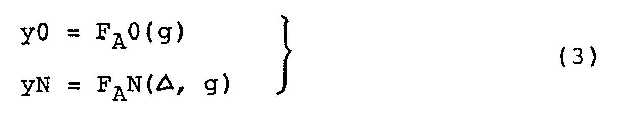
- In the detection system A shown in Figure 4, the following relation is satisfied:
y0 = g tanϑ₀ (4)
In the detection system C, the following relation is satisfied:
y1 = (L+2g-f1)/(f1-g)·Δ (5)
It will be understood from the foregoing that the positional deviation Δ and the interval g can be determined in accordance with equations (A), (4) and (5) and by using measured values of d1 and d2. While the distances D1 and D2 are predetermined in accordance with the design specifications of the physical optic elements, they can be detected by trial printing. - Figure 6 is a schematic representation similar to Figure 4, but shows a major portion of a second embodiment of the present invention. In Figure 6, the device includes detection systems B and C having substantially the same functions as of the detection systems B and C shown in Figure 3.
- Physical optic element Z7 has a concave lens function having a focal point F2 and a focal length f2 and, as a light flux l₁ is projected on the physical optic element Z7, the element Z7 produces first order diffraction light l₈ which is in the form of a divergent beam. The diffraction light l₈ enters another physical optic element Z8 having a convex lens function, whereby first order diffraction light l₉ whose direction of diffraction is changeable with a positional deviation Δ is produced. The diffraction light l₉ is focused at a position spaced from the optical axis by a distance y2. The amount of distance y2 at this time is dependent upon the deviation Δ and the interval g. The optical path for the lights l₁, l₈ and l₉ serves to provide a detection system D.
- In this embodiment, the deviation Δ and the interval g can be detected from two relations, such as follows, which are concerned with the deviation Δ and the interval g:

- The detection systems C and D correspond to any one of Equation "y1 = FA1(Δ, g)" and "y2 = FA2(Δ, g)", and the detection system B provides a reference position C2.
- Where the point C2 is used as the reference position, from Figure 6, it follows that:
y1 = d3 - D3
y2 = d4 - D4
From these relations, the distances y1 and y2 are detected. - In the present embodiment, with regard to the detection system D, the distance y2 is detected in the following manner:
Δ:y2 = (f2+g) : (f2+g+L+g)
∴ y2 = (L+2g+f2)/(f2+g)·Δ (7)
By using equations (5), (6) and (7)and from measured values of d3 and d4, the positional deviation Δ and the interval g can be detected. - Since the center of gravity of the light spot formed by a zero-th order diffraction light component l₁₀ of the light l₆ is always coincident with the optical axis a3, regardless of any shift of the position of the
second object 2, it may be used in place of the detection system B. In that occasion, the point C5 provides a reference position. Such an embodiment will be explained below. - Figure 7 is a schematic representation of a major portion of a third embodiment of the present invention. While in this embodiment flight flux l₁ is incident on the
first object 1 with an angle ϑ, basic operation of this embodiment is substantially the same as that of the second embodiment shown in Figure 6. - Those detection systems shown in Figure 7 are of the same structure as of the detection systems C and D shown in Figure 6.
- One important feature of the present embodiment, as compared with the Figure 6 embodiment, resides in that as a reference position the center of gravity of light l₁₀ impinging on the point C5 is detected. Detection of the point C5 leads to that, when the deviation between the first and
second objects - It will be understood from the foregoing that, when the first and
second objects
Δ1 = Δ + δ1
Δ2 = Δ + δ2 - Figure 8 shows examples of patterns which can be used as the physical optic elements Z3, Z7, Z5 and Z8 provided on the first and
second objects - Figure 9 is a schematic representation similar to Figure 4, but shows a major portion of a fourth embodiment of the present invention. In this embodiment, physical optic element Z9 has a concave lens function having a focal point F3 and a focal length f3, and physical optic element Z10 has a convex lens function having a focal point F4 and a focal length f4. There are provided additional physical optic elements Z11 and Z12 having a convex lens function and a concave lens function, respectively.
- In the present embodiment, each of the physical optic elements Z9 and Z10 provided on the
first object 1 has an eccentricity by which the focal point position is deviated by ε3 or ε4 from a normal to the physical optic element. As a result, even in correct alignment, the optical axes of the physical optic elements on the first and second objects are mutually deviated (by an amount δ). - Accordingly, as in the embodiment of Figure 7, if the first and second objects are deviated by Δ, then Δ in equation (6) is substituted in the following manner:
Δ3 = Δ + δ3
Δ4 = Δ + δ4 - When, in this embodiment, the light l₁ is incident on the physical optic elements Z9 and Z10, there are produced first order diffraction lights l₁₂ and l₁₄. The lights l₁₂ and l₁₄ are projected on the physical optic elements Z11 and Z12 and, in response, there are produced first order diffraction lights l₁₃ and l₁₅ which are focused at points spaced by distances y3 and y4, respectively, from the optical axes a5 and a6, respectively.
- In this embodiment, the optical path for the lights l₁ - l₁₃ serves to provide a detection system E, and in this detection system E the following relations are provided:
Δ3:y3 = x:(x+L+g)
Δ3:ε3 = x:(f3+g-x)
∴ y3 = [(L+g)/(f3+g)](ε3+Δ3) + Δ3 (8)
On the other hand, the optical path for lights l₁ to l₁₅ serves to provide a detection system F, and in this detection system F the following relation is provided:
y4 = [(L+g)/(f4-g)](ε4+Δ4) + Δ4 (9) - The point C2 of the center of gravity of light in the detection system B provides, like the detection system B shown in Figure 4, a reference for the other positions. As compared with the foregoing embodiments, in this embodiment it is not necessary that the optical axis of the detection system B is positioned intermediate of the optical axes of the other two detection systems. It may be positioned anywhere.
- In the present embodiment, the distances y3 and y4 can be detected by the following equations:
y3 = d5 - D5
y4 = (D5 + D6) - d6 - Figure 10 is a schematic representation similar to Figure 4, but shows a major portion of a fifth embodiment of the present invention. Physical optic elements Z13 and Z14 are provided and they have a convex lens function and a concave lens function, respectively.
- In the illustration state, the interval g between the first and
second objects - The functional form of FA3(Δ, g) can be expressed in the following manner:
- In Figure 10, it is assumed that the focal lengths of the physical optic elements Z13 and Z14 are denoted by f₁₃ and f₁₄, respectively, and that the size of a spot formed on the
sensor 4 surface by the diffraction light from the physical optic elements Z13 and Z14 becomes smallest when the interval between themask 1 and thewafer 2 is equal to g₀. In that occasion, the following relation is satisfied:
-1/f₁₄ + 1/(f₁₃-g₀) = 1/(L+g₀)
That is, the distance from the wafer to the position of such smallest spot, along the optical axis, is equal to L+g₀. If, in this occasion, the interval between the mask and the wafer changes to g, then a smallest spot is formed at a distance, along the optical axis, which can be expressed as follows:
[-1/f₁₄ + 1/(f₁₃-g)]⁻¹ = f₁₄(f₁₃-g)/(f₁₄-f₁₃+g)
This means that a minimum spot of diffraction light is formed at a position spaced in the direction of the optical axis from the sensor surface by:
f₁₄(f₁₃-g)/(f₁₄-f₁₃+g) - (L+g) - It is seen from the above that the size (expansion) of a signal light spot on the sensor increases both when the mask-to-wafer interval is larger than the predetermined interval g₀ and when the mask-to-wafer interval is smaller than g₀. The relationship can be predetected by selecting some values with which the mask-to-wafer interval is changed from g₀ by Δg. Namely, it is detectable in preparation in terms of the half width of the spot on the sensor, i.e.:

- Further, if there is a relative positional deviation between the mask and the wafer in a direction parallel to them, the effective diffraction area of the physical optic element Z14 as it receives the light l₁₆ to diffract the same, reduces. This leads to that, due to the diffraction by the effective pattern area of the physical optic element Z14, the expansion of the spot of the diffraction light formed on the sensor surface is changeable. Namely, the spot becomes smallest when Δ = 0. As the deviation Δ increases, the effective pattern area of the physical optic element Z14 becomes narrower, relatively to the light l₁₆ and the expansion of the spot on the sensor becomes larger.
- Assuming now that the pattern area size of the physical optic element Z14 is S, with the deviation between the mask and the wafer the effective pattern area size of the physical optic element Z14 reduces in relative by (S-Δ)/S and, therefore, substantially in inverse proportion to this the size of the spot on the sensor increases (provided that S » Δ).
- Including Δ and g, from the foregoing it follows that:

- On the other hand, the distance y5 between the optical axis a7 and the center of gravity of the spot C9 is given by:
y5 = FA5(Δ, g) = (L+2g-f₁₃)/(f₁₃-g) x Δ
wherein f₁₃ is the focal length of the physical optic element Z13. From this, it follows that:
- In this embodiment, there are two sites, before and after the imaging point, at which the half width α has the same value. Thus, by moving the
second object 2 rightwardly or leftwardly, whether the point is before or after the imaging point is discriminated. - The present embodiment is a special case where two equations are obtained from one detection system.
- In this embodiment, with a larger angle of convergence of light, the change in the half width of light per unit length in the direction of the optical axis is larger. Therefore, the change in the half width with the change in the interval g can be detected with a good sensitivity. Namely, the depth of focus of the lens system becomes short and, as a result, the change in the half width α can be detected with a good sensitivity.
- It is seen from the drawing that with a larger length of each physical optic element Z13 or Z14 in the alignment direction, better sensitivity of the detection system is attainable.
- While for measurement of the distance y5 an arrangement such as the detection system B which can provide a reference position is necessary, use may be made as in the fifth embodiment of such light l₁₆ that passes through the physical optic element Z14 as zero-th order diffraction light and impinges on the
sensor 4. - Figure 11 is a schematic representation of a major portion of a sixth embodiment of the present invention. This embodiment corresponds to a modified form of the detection system A shown in Figure 4, wherein the distance y0 is replaced by a quantity y6 which is dependent only upon the interval g between the first and
second objects - In Figure 11, as light flux l₁ is incident on physical optic element Z15 having a convex lens function, there is produced first order diffraction light l₁₈ which is in the form of a convergent beam. As the diffraction light l₁₈ impinges on a physical optic element Z16 having only a deflecting function, zero-th order diffraction light is transmitted and emanates therefrom. At the same time, first order diffraction light l₂₀ with the chief ray being deflected in a direction of an angle ϑ6, is produced.
- On the other hand, the zero-th order diffraction light component of the diffraction light l₁₈ impinges on a physical optic element Z17 which is provided on the first object and which has only a light deflecting function, in response to which impingement there is produced first order diffraction light l₂₁ whose chief ray being deflected in a direction of an angle ϑ6. These diffraction lights l₂₀ and l₂₁ are focused at points C10 and C11, respectively, on the
sensor 4 surface. - In this embodiment, the optical path for the lights l₁ to l₂₀ or l₂₁ serves to provide a detection system G.
- In this embodiment, the distance y6 between the points C10 and C11 can be detected by the following equation:
y6 = g·tanϑ6
From this, the interval g can be detected. The remaining portion of this embodiment is substantially the same as the corresponding portion of the Figure 4 embodiment and, like the first embodiment, the values of g and Δ can be detected. - In accordance with the present invention, any positional deviation Δ between the first and second objects as well as the interval g between the first and second objects are detected. This avoids incorrect discrimination of the state of alignment between these objects. Also, it is possible to correct the detected deviation Δ by using the value of the interval g. As a result, it is possible to provide an alignment system having high alignment precision and attaining high throughput. As an example, where the alignment is to be made by using the detecting system C of the alignment system of the present invention, under the conditions of g = 30 microns, f1 = 100 microns, L = 18000 microns and y1 = 300 microns, and if there is an error of 0.3 micron in the interval g, there occurs an error of 0.005 micron in the deviation Δ. Therefore, where the alignment with a precision of 0.01 micron is desired, it is necessary to suppress the error in the interval g to 0.3 micron or less.
- In accordance with the present invention, the positional deviation Δ and the interval g can be measured at the same time and the error in the interval g can be reduced to 0.3 micron or less. As a result, an alignment precision of 0.01 micron is attainable.
- Further, in accordance with the present invention, physical optic element means is used both for the detection of the positional deviation Δ and for the detection of the interval g. This reduces the number of required physical optic elements or lights, thus making the detection system simple and reducing in size of the apparatus as a whole.
- Additionally, quantities on a sensor such as the distances y1 and y2 can be detected each in terms of a difference between two values. It is therefore possible to cancel any error which might be caused by inclination of the
second object 2 in the alignment direction. As a result, more accurate alignment is assured. - While the invention has been described with reference to the structures disclosed herein, it is not confined to the details set forth and this application is intended to cover such modifications or changes as may come within the purposes of the improvements or the scope of the following claims.
Claims (6)
light source means for projecting light to the first and second objects;
photodetecting means for detecting light from one of the first and second objects irradiated with the light from said light source means, said detecting means being operable to detect first light whose position of incidence upon a predetermined plane is dependent upon the positional relationship of the first and second objects in a direction along the interval therebetween and in a direction perpendicular to the interval, second light whose position of incidence upon said predetermined plane is dependent upon the positional relationship of the first and second objects in the direction of the interval therebetween, and third light whose position of incidence upon said predetermined plane is independent of the positional relationship of the first and second objects in both of the direction of the interval and the direction perpendicular to the interval; and
positional relationship detecting means for detecting the positional relationship of the first and second objects in the direction of the interval and the direction perpendicular to the interval, on the basis of the detection by said photodetecting means.
light source means for projecting light to the first and second objects;
photodetecting means for detecting light from one of the first and second objects irradiated with the light from said light source means;
interval detecting means for detecting the positional relationship of the first and second objects in a direction of the interval therebetween, on the basis of the detection by said photodetecting means; and
positional relationship detecting means for detecting the positional relationship of the first and second objects in a direction perpendicular to the interval therebetween, on the basis of the detection by said photodetecting means and said interval detecting means, wherein a value detected by said positional relationship detecting means is independent of the positional relationship of the first and second objects in the direction of the interval therebetween.
projecting light to the first and second objects;
receiving light from one of the first and second objects irradiated with the light from said light source means and detecting first light whose position of incidence upon a predetermined plane is dependent upon the positional relationship of the first and second objects in a direction along the interval therebetween and in a direction perpendicular to the interval, second light whose position of incidence upon said predetermined plane is dependent upon the positional relationship of the first and second objects in the direction of the interval therebetween, and third light whose position of incidence upon said predetermined plane is independent of the positional relationship of the first and second objects in both of the direction of the interval and the direction perpendicular to the interval; and
detecting the positional relationship of the first and second objects in the direction of the interval and the direction perpendicular to the interval, on the basis of the first detection.
Applications Claiming Priority (2)
| Application Number | Priority Date | Filing Date | Title |
|---|---|---|---|
| JP63225804A JP2546350B2 (en) | 1988-09-09 | 1988-09-09 | Alignment device |
| JP225804/88 | 1988-09-09 |
Publications (3)
| Publication Number | Publication Date |
|---|---|
| EP0358512A2 true EP0358512A2 (en) | 1990-03-14 |
| EP0358512A3 EP0358512A3 (en) | 1990-12-27 |
| EP0358512B1 EP0358512B1 (en) | 1997-07-23 |
Family
ID=16835048
Family Applications (1)
| Application Number | Title | Priority Date | Filing Date |
|---|---|---|---|
| EP89309095A Expired - Lifetime EP0358512B1 (en) | 1988-09-09 | 1989-09-07 | Position detecting method and apparatus |
Country Status (4)
| Country | Link |
|---|---|
| US (1) | US5148037A (en) |
| EP (1) | EP0358512B1 (en) |
| JP (1) | JP2546350B2 (en) |
| DE (1) | DE68928192T2 (en) |
Families Citing this family (80)
| Publication number | Priority date | Publication date | Assignee | Title |
|---|---|---|---|---|
| JP2789787B2 (en) * | 1990-06-01 | 1998-08-20 | キヤノン株式会社 | Position detection device |
| JPH0540013A (en) * | 1991-08-05 | 1993-02-19 | Canon Inc | Deviation measuring method and exposing device using it |
| JPH0590126A (en) * | 1991-09-27 | 1993-04-09 | Canon Inc | Position detection equipment |
| CA2078732A1 (en) * | 1991-09-27 | 1993-03-28 | Koichi Sentoku | Displacement measuring device and displacement measuring method |
| US5495336A (en) * | 1992-02-04 | 1996-02-27 | Canon Kabushiki Kaisha | Position detecting method for detecting a positional relationship between a first object and a second object |
| JPH06137830A (en) * | 1992-10-23 | 1994-05-20 | Canon Inc | Interference measuring method and its device |
| US5861952A (en) * | 1992-11-16 | 1999-01-19 | Canon Kabushiki Kaisha | Optical inspection method and apparatus including intensity modulation of a light beam and detection of light scattered at an inspection position |
| US5455679A (en) * | 1993-02-22 | 1995-10-03 | Canon Kabushiki Kaisha | Position detecting system |
| JPH0786121A (en) * | 1993-06-30 | 1995-03-31 | Canon Inc | Shift measuring method and position detector employing the same |
| JPH0743313A (en) * | 1993-07-29 | 1995-02-14 | Canon Inc | Foreign matter inspection system and production of semiconductor device using it |
| JP3183046B2 (en) * | 1994-06-06 | 2001-07-03 | キヤノン株式会社 | Foreign particle inspection apparatus and method for manufacturing semiconductor device using the same |
| US6873087B1 (en) | 1999-10-29 | 2005-03-29 | Board Of Regents, The University Of Texas System | High precision orientation alignment and gap control stages for imprint lithography processes |
| EP1303792B1 (en) * | 2000-07-16 | 2012-10-03 | Board Of Regents, The University Of Texas System | High-resolution overlay alignement methods and systems for imprint lithography |
| EP2270592B1 (en) | 2000-07-17 | 2015-09-02 | Board of Regents, The University of Texas System | Method of forming a pattern on a substrate |
| AU2001280980A1 (en) * | 2000-08-01 | 2002-02-13 | Board Of Regents, The University Of Texas System | Methods for high-precision gap and orientation sensing between a transparent template and substrate for imprint lithography |
| US8016277B2 (en) | 2000-08-21 | 2011-09-13 | Board Of Regents, The University Of Texas System | Flexure based macro motion translation stage |
| JP2004523906A (en) * | 2000-10-12 | 2004-08-05 | ボード・オブ・リージエンツ,ザ・ユニバーシテイ・オブ・テキサス・システム | Templates for room-temperature and low-pressure micro and nano-transfer lithography |
| US6964793B2 (en) | 2002-05-16 | 2005-11-15 | Board Of Regents, The University Of Texas System | Method for fabricating nanoscale patterns in light curable compositions using an electric field |
| US7037639B2 (en) | 2002-05-01 | 2006-05-02 | Molecular Imprints, Inc. | Methods of manufacturing a lithography template |
| US6926929B2 (en) | 2002-07-09 | 2005-08-09 | Molecular Imprints, Inc. | System and method for dispensing liquids |
| US7077992B2 (en) | 2002-07-11 | 2006-07-18 | Molecular Imprints, Inc. | Step and repeat imprint lithography processes |
| US7019819B2 (en) * | 2002-11-13 | 2006-03-28 | Molecular Imprints, Inc. | Chucking system for modulating shapes of substrates |
| US6900881B2 (en) | 2002-07-11 | 2005-05-31 | Molecular Imprints, Inc. | Step and repeat imprint lithography systems |
| US6932934B2 (en) | 2002-07-11 | 2005-08-23 | Molecular Imprints, Inc. | Formation of discontinuous films during an imprint lithography process |
| US6908861B2 (en) * | 2002-07-11 | 2005-06-21 | Molecular Imprints, Inc. | Method for imprint lithography using an electric field |
| US7070405B2 (en) | 2002-08-01 | 2006-07-04 | Molecular Imprints, Inc. | Alignment systems for imprint lithography |
| US7027156B2 (en) | 2002-08-01 | 2006-04-11 | Molecular Imprints, Inc. | Scatterometry alignment for imprint lithography |
| US6916584B2 (en) | 2002-08-01 | 2005-07-12 | Molecular Imprints, Inc. | Alignment methods for imprint lithography |
| US7071088B2 (en) | 2002-08-23 | 2006-07-04 | Molecular Imprints, Inc. | Method for fabricating bulbous-shaped vias |
| US8349241B2 (en) | 2002-10-04 | 2013-01-08 | Molecular Imprints, Inc. | Method to arrange features on a substrate to replicate features having minimal dimensional variability |
| US6929762B2 (en) | 2002-11-13 | 2005-08-16 | Molecular Imprints, Inc. | Method of reducing pattern distortions during imprint lithography processes |
| US6980282B2 (en) * | 2002-12-11 | 2005-12-27 | Molecular Imprints, Inc. | Method for modulating shapes of substrates |
| US6871558B2 (en) * | 2002-12-12 | 2005-03-29 | Molecular Imprints, Inc. | Method for determining characteristics of substrate employing fluid geometries |
| TW200500811A (en) * | 2002-12-13 | 2005-01-01 | Molecular Imprints Inc | Magnification correction employing out-of-plane distortion of a substrate |
| US7452574B2 (en) | 2003-02-27 | 2008-11-18 | Molecular Imprints, Inc. | Method to reduce adhesion between a polymerizable layer and a substrate employing a fluorine-containing layer |
| US7122079B2 (en) | 2004-02-27 | 2006-10-17 | Molecular Imprints, Inc. | Composition for an etching mask comprising a silicon-containing material |
| US7179396B2 (en) | 2003-03-25 | 2007-02-20 | Molecular Imprints, Inc. | Positive tone bi-layer imprint lithography method |
| US7396475B2 (en) | 2003-04-25 | 2008-07-08 | Molecular Imprints, Inc. | Method of forming stepped structures employing imprint lithography |
| US7157036B2 (en) | 2003-06-17 | 2007-01-02 | Molecular Imprints, Inc | Method to reduce adhesion between a conformable region and a pattern of a mold |
| US7150622B2 (en) * | 2003-07-09 | 2006-12-19 | Molecular Imprints, Inc. | Systems for magnification and distortion correction for imprint lithography processes |
| US7136150B2 (en) | 2003-09-25 | 2006-11-14 | Molecular Imprints, Inc. | Imprint lithography template having opaque alignment marks |
| US7090716B2 (en) | 2003-10-02 | 2006-08-15 | Molecular Imprints, Inc. | Single phase fluid imprint lithography method |
| US8211214B2 (en) | 2003-10-02 | 2012-07-03 | Molecular Imprints, Inc. | Single phase fluid imprint lithography method |
| US8076386B2 (en) | 2004-02-23 | 2011-12-13 | Molecular Imprints, Inc. | Materials for imprint lithography |
| US7906180B2 (en) | 2004-02-27 | 2011-03-15 | Molecular Imprints, Inc. | Composition for an etching mask comprising a silicon-containing material |
| US7768624B2 (en) * | 2004-06-03 | 2010-08-03 | Board Of Regents, The University Of Texas System | Method for obtaining force combinations for template deformation using nullspace and methods optimization techniques |
| CN101379435A (en) * | 2004-06-03 | 2009-03-04 | 得克萨斯州大学系统董事会 | System and method for improvement of alignment and overlay for microlithography |
| KR101193918B1 (en) * | 2004-06-03 | 2012-10-29 | 몰레큘러 임프린츠 인코퍼레이티드 | Fluid dispensing and drop-on-demand dispensing for nano-scale menufacturing |
| US20050270516A1 (en) * | 2004-06-03 | 2005-12-08 | Molecular Imprints, Inc. | System for magnification and distortion correction during nano-scale manufacturing |
| US20070228593A1 (en) * | 2006-04-03 | 2007-10-04 | Molecular Imprints, Inc. | Residual Layer Thickness Measurement and Correction |
| US7785526B2 (en) * | 2004-07-20 | 2010-08-31 | Molecular Imprints, Inc. | Imprint alignment method, system, and template |
| US7939131B2 (en) | 2004-08-16 | 2011-05-10 | Molecular Imprints, Inc. | Method to provide a layer with uniform etch characteristics |
| US7547504B2 (en) | 2004-09-21 | 2009-06-16 | Molecular Imprints, Inc. | Pattern reversal employing thick residual layers |
| US7630067B2 (en) | 2004-11-30 | 2009-12-08 | Molecular Imprints, Inc. | Interferometric analysis method for the manufacture of nano-scale devices |
| US7292326B2 (en) * | 2004-11-30 | 2007-11-06 | Molecular Imprints, Inc. | Interferometric analysis for the manufacture of nano-scale devices |
| US20070231421A1 (en) | 2006-04-03 | 2007-10-04 | Molecular Imprints, Inc. | Enhanced Multi Channel Alignment |
| KR20070086766A (en) * | 2004-12-01 | 2007-08-27 | 몰레큘러 임프린츠 인코퍼레이티드 | Methods of exposure for the purpose of thermal management for imprint lithography processes |
| US7811505B2 (en) | 2004-12-07 | 2010-10-12 | Molecular Imprints, Inc. | Method for fast filling of templates for imprint lithography using on template dispense |
| US20060177532A1 (en) * | 2005-02-04 | 2006-08-10 | Molecular Imprints, Inc. | Imprint lithography method to control extrusion of a liquid from a desired region on a substrate |
| US7636999B2 (en) | 2005-01-31 | 2009-12-29 | Molecular Imprints, Inc. | Method of retaining a substrate to a wafer chuck |
| US7635263B2 (en) | 2005-01-31 | 2009-12-22 | Molecular Imprints, Inc. | Chucking system comprising an array of fluid chambers |
| US20070228608A1 (en) * | 2006-04-03 | 2007-10-04 | Molecular Imprints, Inc. | Preserving Filled Features when Vacuum Wiping |
| US8808808B2 (en) | 2005-07-22 | 2014-08-19 | Molecular Imprints, Inc. | Method for imprint lithography utilizing an adhesion primer layer |
| US20070064384A1 (en) * | 2005-08-25 | 2007-03-22 | Molecular Imprints, Inc. | Method to transfer a template transfer body between a motion stage and a docking plate |
| US7665981B2 (en) * | 2005-08-25 | 2010-02-23 | Molecular Imprints, Inc. | System to transfer a template transfer body between a motion stage and a docking plate |
| US20070074635A1 (en) * | 2005-08-25 | 2007-04-05 | Molecular Imprints, Inc. | System to couple a body and a docking plate |
| US7670534B2 (en) | 2005-09-21 | 2010-03-02 | Molecular Imprints, Inc. | Method to control an atmosphere between a body and a substrate |
| US7906058B2 (en) | 2005-12-01 | 2011-03-15 | Molecular Imprints, Inc. | Bifurcated contact printing technique |
| US7803308B2 (en) | 2005-12-01 | 2010-09-28 | Molecular Imprints, Inc. | Technique for separating a mold from solidified imprinting material |
| MY144847A (en) | 2005-12-08 | 2011-11-30 | Molecular Imprints Inc | Method and system for double-sided patterning of substrates |
| US7670530B2 (en) | 2006-01-20 | 2010-03-02 | Molecular Imprints, Inc. | Patterning substrates employing multiple chucks |
| US7460231B2 (en) * | 2006-03-27 | 2008-12-02 | Asml Netherlands B.V. | Alignment tool for a lithographic apparatus |
| US8850980B2 (en) | 2006-04-03 | 2014-10-07 | Canon Nanotechnologies, Inc. | Tessellated patterns in imprint lithography |
| US8142850B2 (en) | 2006-04-03 | 2012-03-27 | Molecular Imprints, Inc. | Patterning a plurality of fields on a substrate to compensate for differing evaporation times |
| US7802978B2 (en) | 2006-04-03 | 2010-09-28 | Molecular Imprints, Inc. | Imprinting of partial fields at the edge of the wafer |
| JP5306989B2 (en) | 2006-04-03 | 2013-10-02 | モレキュラー・インプリンツ・インコーポレーテッド | Method for simultaneously patterning a substrate having a plurality of fields and alignment marks |
| US7547398B2 (en) | 2006-04-18 | 2009-06-16 | Molecular Imprints, Inc. | Self-aligned process for fabricating imprint templates containing variously etched features |
| US8012395B2 (en) | 2006-04-18 | 2011-09-06 | Molecular Imprints, Inc. | Template having alignment marks formed of contrast material |
| WO2007124007A2 (en) * | 2006-04-21 | 2007-11-01 | Molecular Imprints, Inc. | Method for detecting a particle in a nanoimprint lithography system |
| JP5027468B2 (en) * | 2006-09-15 | 2012-09-19 | 日本ミクロコーティング株式会社 | Probe cleaning or probe processing sheet and probe processing method |
Citations (2)
| Publication number | Priority date | Publication date | Assignee | Title |
|---|---|---|---|---|
| GB2073950A (en) * | 1980-04-11 | 1981-10-21 | Western Electric Co | Method and apparatus for mask/wafer alignment |
| US4360273A (en) * | 1980-02-14 | 1982-11-23 | Sperry Corporation | Optical alignment of masks for X-ray lithography |
Family Cites Families (10)
| Publication number | Priority date | Publication date | Assignee | Title |
|---|---|---|---|---|
| US4037969A (en) * | 1976-04-02 | 1977-07-26 | Bell Telephone Laboratories, Incorporated | Zone plate alignment marks |
| US4539482A (en) * | 1980-10-09 | 1985-09-03 | Canon Kabushiki Kaisha | Reading apparatus |
| US4398824A (en) * | 1981-04-15 | 1983-08-16 | Bell Telephone Laboratories, Incorporated | Wafer tilt compensation in zone plate alignment system |
| US4629313A (en) * | 1982-10-22 | 1986-12-16 | Nippon Kogaku K.K. | Exposure apparatus |
| US4636626A (en) * | 1983-01-14 | 1987-01-13 | Nippon Kogaku K.K. | Apparatus for aligning mask and wafer used in semiconductor circuit element fabrication |
| US4514858A (en) * | 1983-03-15 | 1985-04-30 | Micronix Partners | Lithography system |
| US4656347A (en) * | 1984-01-30 | 1987-04-07 | Nippon Telegraph & Telephone Public Corporation | Diffraction grating position adjuster using a grating and a reflector |
| JPS61111402A (en) * | 1984-11-06 | 1986-05-29 | Nippon Kogaku Kk <Nikon> | Position detector |
| US4815854A (en) * | 1987-01-19 | 1989-03-28 | Nec Corporation | Method of alignment between mask and semiconductor wafer |
| US4904087A (en) * | 1987-07-06 | 1990-02-27 | American Telephone & Telegraph Co., At&T Bell Laboratories | Method for aligning photomasks |
-
1988
- 1988-09-09 JP JP63225804A patent/JP2546350B2/en not_active Expired - Fee Related
-
1989
- 1989-09-07 EP EP89309095A patent/EP0358512B1/en not_active Expired - Lifetime
- 1989-09-07 DE DE68928192T patent/DE68928192T2/en not_active Expired - Fee Related
-
1991
- 1991-03-26 US US07/675,059 patent/US5148037A/en not_active Expired - Fee Related
Patent Citations (2)
| Publication number | Priority date | Publication date | Assignee | Title |
|---|---|---|---|---|
| US4360273A (en) * | 1980-02-14 | 1982-11-23 | Sperry Corporation | Optical alignment of masks for X-ray lithography |
| GB2073950A (en) * | 1980-04-11 | 1981-10-21 | Western Electric Co | Method and apparatus for mask/wafer alignment |
Non-Patent Citations (1)
| Title |
|---|
| JOURNAL OF VACUUM SCIENCE AND TECHNOLOGY: PART B. vol. B1, no. 4, October 1983, NEW YORK US pages 1276 - 1279; H. Kinoshita et al.: "A dual grating alignment technique for x-ray lithography" * |
Also Published As
| Publication number | Publication date |
|---|---|
| DE68928192D1 (en) | 1997-08-28 |
| JP2546350B2 (en) | 1996-10-23 |
| DE68928192T2 (en) | 1997-11-27 |
| JPH0274803A (en) | 1990-03-14 |
| US5148037A (en) | 1992-09-15 |
| EP0358512B1 (en) | 1997-07-23 |
| EP0358512A3 (en) | 1990-12-27 |
Similar Documents
| Publication | Publication Date | Title |
|---|---|---|
| EP0358512A2 (en) | Position detecting method and apparatus | |
| JP3570728B2 (en) | Lithographic projector with off-axis alignment unit | |
| KR100632889B1 (en) | Alignment system and methods for lithographic systems using at least two wavelengths | |
| US5200800A (en) | Position detecting method and apparatus | |
| EP0329430B1 (en) | Position detecting device | |
| US4566795A (en) | Alignment apparatus | |
| EP0488798B1 (en) | Position detecting method | |
| US5235408A (en) | Position detecting method and apparatus | |
| EP0468741B1 (en) | Position detecting method | |
| US5160848A (en) | Device for detecting the relative position between opposed first and second objects | |
| US5495336A (en) | Position detecting method for detecting a positional relationship between a first object and a second object | |
| US5225892A (en) | Positional deviation detecting method | |
| EP0455443B1 (en) | Positional deviation detecting method and apparatus | |
| US5325176A (en) | Position detecting method and apparatus including Fraunhofer diffraction detector | |
| US6426508B1 (en) | Surface-position detection device, a projection exposure apparatus using the device, and a device manufacturing method using the apparatus | |
| EP0358425A2 (en) | Position detecting method and apparatus | |
| US5717492A (en) | Position detecting apparatus and a method for manufacturing semiconductor devices using the apparatus | |
| US5294980A (en) | Positioning detecting method and apparatus | |
| US5319444A (en) | Position detecting method and apparatus | |
| US5455679A (en) | Position detecting system | |
| EP0333326B1 (en) | Position detecting method and apparatus | |
| JP3368017B2 (en) | Position detecting device and method of manufacturing semiconductor device using the same | |
| US5148035A (en) | Position detecting method and apparatus | |
| US5148038A (en) | Device for detecting positional relationship between two objects | |
| EP0455446B1 (en) | Position detecting method and apparatus |
Legal Events
| Date | Code | Title | Description |
|---|---|---|---|
| PUAI | Public reference made under article 153(3) epc to a published international application that has entered the european phase |
Free format text: ORIGINAL CODE: 0009012 |
|
| AK | Designated contracting states |
Kind code of ref document: A2 Designated state(s): DE FR GB NL |
|
| PUAL | Search report despatched |
Free format text: ORIGINAL CODE: 0009013 |
|
| AK | Designated contracting states |
Kind code of ref document: A3 Designated state(s): DE FR GB NL |
|
| 17P | Request for examination filed |
Effective date: 19901231 |
|
| 17Q | First examination report despatched |
Effective date: 19930707 |
|
| GRAG | Despatch of communication of intention to grant |
Free format text: ORIGINAL CODE: EPIDOS AGRA |
|
| GRAH | Despatch of communication of intention to grant a patent |
Free format text: ORIGINAL CODE: EPIDOS IGRA |
|
| GRAH | Despatch of communication of intention to grant a patent |
Free format text: ORIGINAL CODE: EPIDOS IGRA |
|
| GRAA | (expected) grant |
Free format text: ORIGINAL CODE: 0009210 |
|
| AK | Designated contracting states |
Kind code of ref document: B1 Designated state(s): DE FR GB NL |
|
| PG25 | Lapsed in a contracting state [announced via postgrant information from national office to epo] |
Ref country code: FR Effective date: 19970723 |
|
| REF | Corresponds to: |
Ref document number: 68928192 Country of ref document: DE Date of ref document: 19970828 |
|
| EN | Fr: translation not filed | ||
| PLBE | No opposition filed within time limit |
Free format text: ORIGINAL CODE: 0009261 |
|
| STAA | Information on the status of an ep patent application or granted ep patent |
Free format text: STATUS: NO OPPOSITION FILED WITHIN TIME LIMIT |
|
| 26N | No opposition filed | ||
| REG | Reference to a national code |
Ref country code: GB Ref legal event code: IF02 |
|
| PGFP | Annual fee paid to national office [announced via postgrant information from national office to epo] |
Ref country code: GB Payment date: 20030826 Year of fee payment: 15 |
|
| PGFP | Annual fee paid to national office [announced via postgrant information from national office to epo] |
Ref country code: DE Payment date: 20030919 Year of fee payment: 15 |
|
| PGFP | Annual fee paid to national office [announced via postgrant information from national office to epo] |
Ref country code: NL Payment date: 20030930 Year of fee payment: 15 |
|
| PG25 | Lapsed in a contracting state [announced via postgrant information from national office to epo] |
Ref country code: GB Free format text: LAPSE BECAUSE OF NON-PAYMENT OF DUE FEES Effective date: 20040907 |
|
| PG25 | Lapsed in a contracting state [announced via postgrant information from national office to epo] |
Ref country code: NL Free format text: LAPSE BECAUSE OF NON-PAYMENT OF DUE FEES Effective date: 20050401 Ref country code: DE Free format text: LAPSE BECAUSE OF NON-PAYMENT OF DUE FEES Effective date: 20050401 |
|
| GBPC | Gb: european patent ceased through non-payment of renewal fee |
Effective date: 20040907 |
|
| NLV4 | Nl: lapsed or anulled due to non-payment of the annual fee |
Effective date: 20050401 |