EP0360624A2 - Improvements in and relating to electronic game apparatus - Google Patents
Improvements in and relating to electronic game apparatus Download PDFInfo
- Publication number
- EP0360624A2 EP0360624A2 EP89311024A EP89311024A EP0360624A2 EP 0360624 A2 EP0360624 A2 EP 0360624A2 EP 89311024 A EP89311024 A EP 89311024A EP 89311024 A EP89311024 A EP 89311024A EP 0360624 A2 EP0360624 A2 EP 0360624A2
- Authority
- EP
- European Patent Office
- Prior art keywords
- signal
- piece
- playing
- resonant
- transmit
- Prior art date
- Legal status (The legal status is an assumption and is not a legal conclusion. Google has not performed a legal analysis and makes no representation as to the accuracy of the status listed.)
- Granted
Links
Images


Classifications
-
- G—PHYSICS
- G06—COMPUTING; CALCULATING OR COUNTING
- G06F—ELECTRIC DIGITAL DATA PROCESSING
- G06F3/00—Input arrangements for transferring data to be processed into a form capable of being handled by the computer; Output arrangements for transferring data from processing unit to output unit, e.g. interface arrangements
- G06F3/01—Input arrangements or combined input and output arrangements for interaction between user and computer
- G06F3/03—Arrangements for converting the position or the displacement of a member into a coded form
- G06F3/041—Digitisers, e.g. for touch screens or touch pads, characterised by the transducing means
- G06F3/046—Digitisers, e.g. for touch screens or touch pads, characterised by the transducing means by electromagnetic means
-
- A—HUMAN NECESSITIES
- A63—SPORTS; GAMES; AMUSEMENTS
- A63F—CARD, BOARD, OR ROULETTE GAMES; INDOOR GAMES USING SMALL MOVING PLAYING BODIES; VIDEO GAMES; GAMES NOT OTHERWISE PROVIDED FOR
- A63F3/00—Board games; Raffle games
- A63F3/00643—Electric board games; Electric features of board games
-
- A—HUMAN NECESSITIES
- A63—SPORTS; GAMES; AMUSEMENTS
- A63F—CARD, BOARD, OR ROULETTE GAMES; INDOOR GAMES USING SMALL MOVING PLAYING BODIES; VIDEO GAMES; GAMES NOT OTHERWISE PROVIDED FOR
- A63F3/00—Board games; Raffle games
- A63F3/00643—Electric board games; Electric features of board games
- A63F2003/00662—Electric board games; Electric features of board games with an electric sensor for playing pieces
- A63F2003/00665—Electric board games; Electric features of board games with an electric sensor for playing pieces using inductance
Definitions
- This invention relates to electronic game apparatus and in particular to such a game where the role of one of the players is taken over by a computer.
- the invention can typically be applied to board games such as chess in which different pieces or ranks of pieces are to be located.
- One such game consists of a board which can sense the presence of a playing piece on the board. This may be done by means of a switch, such as a reed switch, located beneath each playing square. A magnet is provided within the playing pieces and, as a playing piece is placed on the square, the magnet causes the switch to flip. Electronics are provided to detect this switch action and so determine that a piece has been placed on or removed from the playing square.
- a switch such as a reed switch
- Another presence sensing system is described in our British Patent Application No. 8920204.
- two sets of coils are placed beneath the playing surface, one set to transmit a signal and one set to receive a signal.
- a metal disc is provided in the base of each playing piece.
- An alternating current signal is then sent down each transmit coil in turn and mutually couples with the receive coils. If a playing piece is present on a square, the voltage induced in the receive coil below that square will be significantly reduced, owing to the presence of the metal disc.
- Electronics are provided to detect the induced voltage, compare it with a reference and hence determine whether or not a piece is present on each square.
- Board games which merely detect the presence of a playing piece have the disadvantage that the board cannot directly recognise the rank of, for example, a particular chess piece on a square. This difficulty can be overcome by identifying a piece relative to the position it took at the start of the game.
- the game has to start with the playing pieces in pre-defined positions. The position from and to which a piece is moved (which is detected by the presence sensing system) then allows the identity of the piece to be determined. It is not therefore possible for a player to set up a practice game, as if play was in progress, without entering the position and rank of the playing pieces into the memory.
- Board game apparatus has been developed which can directly identify the rank of particular playing pieces.
- One such apparatus is disclosed in British Patent No. 2 103 943 wherein tuned circuits (resonators) are fitted to each of the pieces.
- These tuned circuits consist of coils which are wound on rod cores and are connected to capacitors.
- the coils within the playing pieces couple with coils built into the board, which stimulate the resonators and pick up the signals produced.
- Different pieces or different piece types have different resonant frequencies, so that the frequency of the signal picked up in a given square indicates the piece type present on that square.
- the coils in the board are arranged in two groups, one group for stimulating (or transmitting) and the other for receiving.
- the coils of each group are connected together in an addressable fashion using a diode at each coil.
- a current pulse is applied to the stimulating (or transmitting) coil, the rapid change of current on the trailing edge of this pulse making the resonator 'ring' at its resonant frequency.
- This signal is picked up by the sensing coil, amplified, and its frequency measured by thresholding, to give a digital signal whose transitions in a fixed period are counted. In the absence of a piece, there is no ringing so few transitions occur.
- the present invention is directed towards apparatus of the kind described in British Patent No. 2 103 943 and seeks to improve on the simplicity and energy efficiency of the system.
- Apparatus of the present invention comprises playing pieces each of which is provided with an electrical resonant circuit.
- a plurality of transmit and receive coils are provided beneath the playing surface and an amplifying circuit is provided between the transmit and receive coils to amplify the signal around the loop consisting of a selected transmit coil, a selected receive coil and the tuned circuit of a playing piece, if present.
- a resonant signal is therefore obtained if a playing piece is positioned on a particular discrete board position.
- Electronic means are provided to detect this resonance and hence the presence of a playing piece.
- the system operates as a feedback oscillator which is initially triggered into oscillation by the inherent noise of the system.
- This apparatus is suitable for use as a non-discriminating system. However, it can readily be adapted to identify the piece or piece type positioned on the board. This is achieved by each piece or type of piece having an electrical resonant circuit tuned to one of a plurality of frequencies, to enable that piece or piece type to be distinguished.
- the apparatus is provided with means to determine the frequency of the resonant signal and hence the identity of the piece. This is preferably achieved by comparing the frequency of the resonant signal with information stored within the apparatus.
- the transmit and receive coils are preferably connected in groups and arranged so that a group of transmit coils intersect with a group of receive coils at only one playing position. Individual transmit and receive coils may be provided for each of the playing positions, but this would mean that the coil selecting means would be unnecessarily complicated. Preferably multiplexers or similar switching devices are provided to select the transmit and the receive coil or coil groups.
- the noise of the apparatus initially induces the tuned circuit of a playing piece into resonance.
- This resonant signal is picked up by the receive coil beneath the playing position, amplified by the amplifying circuit and fed back to the transmit coil.
- This signal then couples with the tuned circuit, to induce a stronger resonant signal with a higher amplitude which is picked up by the receive coil.
- the gain and phase characteristics of the feedback loop should be such as to encourage oscillation, as is known in the art. This means that the playing piece is stimulated into resonance by an a.c. current, the frequency of which is accurately matched to the resonant frequency of the playing piece.
- the ratio of flux in the resonator core to the current in the transmit coil is greatly improved and only a relatively small a.c. current is used.
- the transmit and receive coils require fewer turns, suitably only one, and the resonator coil in the playing pieces may be reduced in size.
- the array of receive and transmit coils is simplified since no diodes are required. Since the coils require a few turns of wire only, the coils are relatively flat and are therefore easily accommodated under the surface of the board.
- the resonant signal detection means suitably comprises a circuit which outputs a signal once the amplitude of the resonant oscillation exceeds a threshold value.
- the board may be made in a number of ways.
- a sheet of plastic, or other suitable material may be mounted on a pin jig and the first set of coils (eg, the transmit coils) wound around the pins.
- a relatively thick piece of material may then be placed over the coils, to reduce the mutual inductance between the transmit and receive coils.
- the receive coils are then wound around the pins and subsequently covered with another plastic sheet.
- the board is then removed from the jig.
- the features around which the coils are wound may be incorporated in the plastic moulding of the board.
- the overlap area of the transmit and receive coils beneath a square is substantially equal to the area of each discrete board position. This allows greater tolerance of the lateral position of playing pieces on a board position. Adjacent board positions are suitably wound in opposite directions to reduce the fields radiated from the board and also reduces the system's susceptibility to external electromagnetic interference.
- the gain of the amplifier should be sufficiently high so that the time taken to obtain a resonant signal is relatively short.
- the mutual inductance between transmit and receive windings is a function of both the area of overlap and also of the separation between the wires.
- the compensating network may have the ability to allow for different coupling factors between different coil pairs.
- the board is manufactured to a high degree of precision, so that the coupling is substantially the same for all pairs.
- a single transformer, preferably aircored, with one winding in series with the drive signal and one winding in series with the sense signal may be provided.
- the system may be allowed to oscillate in the absence of a piece.
- the presence of a piece can then be determined in a number of ways.
- the system may be arranged to oscillate at a frequency that can be easily distinguished from that of any of the pieces.
- the drive current may be cut and a short time later the received signal examined. In the absence of a piece the signal will die away quickly and no frequency will be seen. If, however, the oscillation is due to a piece then its Q-factor will maintain some signal amplitude even a short time after the drive is cut. The frequency of this signal can then be determined and the piece identified.
- Means may be provided to limit the amplitude of the resonant signal.
- this limiting means comprises Automatic Gain Control (AGC) circuitry which ensures that the system operates in its linear region at all times.
- AGC Automatic Gain Control
- Such circuitry limits the gain of the system to such a level that the system oscillates at the frequency with the highest loop gain, ie, the resonant frequency of the resonator.
- the resonant signal is fed to logic circuitry, which may be similar to that described in British Patent No. 2 103 943, in order for the frequency of the resonant signal to be determined.
- the logic circuitry suitably comprises counters for counting the number of clock periods within a pre-defined number of oscillations of the resonant signal. Since the clock period is constant and known, the frequency of the resonant signal can be determined; the higher the frequency the shorter the count. Alternatively the number of oscillations of the resonant frequency in a pre-defined time may be measured directly. The time is defined by a counter clocked from a fixed frequency source. This resonant frequency can then be compared with a pre-set memory which contains the frequency of each playing piece or category of playing piece. Other known circuits or methods may be used to determine the frequency of the resonant signal.
- each playing piece has a unique resonant signal.
- it may only be necessary to identify the rank of each piece in which case twelve frequencies would be necessary, in order to identify a queen, king, bishop, knight, castle and pawn of each colour. Additional pieces and hence resonant frequencies may be required to replace, and hence change the identity of, certain playing pieces on the board.
- a pawn reaches the far side of the board, it is promoted to any chosen rank, excluding king.
- the pieces may have more than one resonant frequency.
- This may be achieved in a number of ways which include: providing two resonant circuits within a playing piece such that when the piece is inverted, the other resonant circuit comes into operation, the cores being designed to shield one resonant circuit from another; providing a switch on the piece, such that when the switch is tripped, the capacitive value, for example, of the piece is altered in a pre-defined manner, the apparatus being programmed to recognise this new resonant frequency; changing the shape of the core or the position of the coil on the core such that the resonant frequency alters in a pre-defined manner.
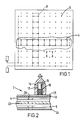
- the board 2 shown in Figure 1 has an array of windings 4 and 6 for transmitting and receiving respectively. Only one transmit coil 4 and one receive coil 6 are shown in Figure 1. However, the other coils are wound in a similar manner. Each transmit coil and each receive coil covers a row or column respectively of, in this case, eight squares, such a board being suitable for use as a chess board. A transmit coil 4 intersects with a receive coil 6 at a unique playing position on the board. The wire is routed around the periphery of each square by means of winding features 8, with adjacent squares being wound in opposite direction. A unique playing square is selected by means of selecting one transmit coil 4 (and hence a row of the chess board) and one receive coil 6 (and hence a column). Multiplexers (see Figure 5) are used to select the transmit and receive coils.
- the board 2 comprises a top layer 18 which, during manufacture, is placed on a pin jig.
- the first set of coils for example the transmit coils 4 are then wound around the pins inserted in holes 20.
- a separator sheet 22 is then placed over the winding in order to reduce the mutual inductance between the two sets of coils.
- the second set of coils 6 is then wound around the pins and finally a bottom layer 24 is placed over the coil 6.
- the board is then removed from the jig and a cosmetic top cover 26 placed over layer 18.
- FIG. 2 also shows a playing piece 10 positioned on the board.
- Each piece 10 has a hollow interior 12 within which is mounted a ferrite core 14.
- a coil 16 made up of a number of turns of thin wire, for example enamelled copper wire.
- a capacitor (not shown) is mounted in parallel with the coil 16 to form a circuit having a natural resonant frequency.
- Each playing piece 10 or each rank of playing piece has a unique resonant circuit and hence resonant frequency, by which it may be identified.
- a variety of combinations of coils and capacitors are needed to provide the different resonant frequencies. In general, lower resonant frequencies require larger diameter cores for the coils if the desired sensing range is to be achieved.
- chessmen there are twelve ranks of chessmen to be identified; namely, a king, a queen, a bishop, a knight, a castle and a pawn of each colour. These may be readily distinguished by spreading the resonant frequency of each piece, over a range of say 50 kHz to 500 kHZ. These resonant frequencies should be geometrically spaced apart. This range is high enough to make the resonators relatively compact yet does not cause excessive electromagnetic interference. Promotion pieces may also be supplied.
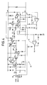
- the amplifying circuit 28 of Figure 3 has a null circuit 30 to balance the residual coupling between the receive and transmit coils.
- a high gain amplifier 32 with low noise and phase shift is then provided to amplify the receive signal.
- the signal derived from the amplifier 32 is used to drive the Automatic Gain Control (AGC) circuit 34 and also passes through a filter 36 and is fed to a variable gain amplifier 38.
- the amplified signal is then either diverted to the drive coils or OV, depending on the gain required by the AGC circuit.
- a signal is derived from the AGC and is fed to a circuit 40 which determines whether an oscillation of adequate amplitude is present.
- a zero-crossing detector 42 produces a signal from which the frequency of the oscillation is determined. Both of these signals PPS and FIN respectively are fed to logic circuits (as shown in Figure 5) which determine the frequency of FIN and, by comparison with the stored frequency of each playing piece, determine the identity of the piece present on the particular playing square
- Figure 4 shows one embodiment of the electronics necessary to generate the resonant signal.
- the null circuit is provided by a transformer 46, preferably a small, air-cored transformer, with one winding in series with the drive signal and the other in series with the sense signal.
- An RC low-pass filter consisting of R15 and C5 is provided to remove high frequency noise from the remaining sense signal.
- the signal then passes to an input amplifier which comprises TR9 and TR10. This amplifier has a typical voltage gain of around 50 and very low noise and phase shift in the frequency band 50-500 KHZ.
- the signal then passes to a high gain intermediate amplifier, which consists of TR11,12,13,14.
- This amplifier has a gain of around 300 and very low phase shift and provides a low output impedance to drive the output and AGC circuits.
- Part of the signal is fed through a filter which comprises R33, L2, C47 and the input resistance of the bias resistor chain R38, R39.
- This filter provides high frequency rejection to remove any excess high frequency noise and improves the circuit stability against spurious oscillations in the absence of a resonator on the square being tested.
- the signal from the filter is then amplified by PNP transistor TR17. This signal, together with a d.c. bias is diverted either to the transmit coils (signal DRIVE) or to OV according to the differential voltage across the bases of the emitter-coupled pair, TR15, TR16.
- TR18 which forms the Automatic Gain Control (AGC) circuit 34.
- AGC Automatic Gain Control
- Voltage comparator 48 acts as a zero crossing detector and outputs a square wave FIN, the frequency of which is equal to the frequency of the resonant signal.
- the output of the AGC circuit TR18 is fed to a second voltage comparator 49 which produces a signal PPS, once a threshold voltage has been exceeded and so stable oscillation has been achieved and hence indicates whether or not a playing piece is present on the board position in question before the resonant frequency is determined.
- the signal FIN passes to a counter 50 and the signal PPS is fed to a microroprocessor 52. Once the amplitude of the resonant signal reaches a threshold value, the signal PPS causes a signal to pass from the microprocesor 52 to the counter 54, the output of which gates counter 50 into operation.
- Counter 54 counts a pre-defined number of oscillations of a fixed frequency sources and hence determines the fixed time period in which counter 50 counts the number of oscillation of the signal FIN. The output of counter 54 at the end of this fixed time period stops the operation of counter 50.
- the count resulting from counter 50 is directly proportional to the resonant frequency of the particular playing piece 10.
- the count is compared with information stored in the memory 58 to determine which playing piece is present.
- Typical response speeds for apparatus of this type allow in excess of 100 positions per second to be tested.
- examples of this invention refer to the game of chess
- electronic game apparatus of this kind may be used in other applications.
- This includes games which require one or more players and one or more games boards, in which all the boards do not reveal the full status of a game; ie, do not show the presence of all operative pieces to all the players.
- This apparatus may also be used in a board which controls the game. For example a board having an on/off feature, degrees of difficulty etc.
- games according to the invention can utilize pieces without resonant circuits, for example when the electronic detection of their presence is not essential.
Abstract
Description
- This invention relates to electronic game apparatus and in particular to such a game where the role of one of the players is taken over by a computer. The invention can typically be applied to board games such as chess in which different pieces or ranks of pieces are to be located.
- Various board games of this type are already known. One such game consists of a board which can sense the presence of a playing piece on the board. This may be done by means of a switch, such as a reed switch, located beneath each playing square. A magnet is provided within the playing pieces and, as a playing piece is placed on the square, the magnet causes the switch to flip. Electronics are provided to detect this switch action and so determine that a piece has been placed on or removed from the playing square.
- Another presence sensing system is described in our British Patent Application No. 8920204. In this system, two sets of coils are placed beneath the playing surface, one set to transmit a signal and one set to receive a signal. A metal disc is provided in the base of each playing piece. An alternating current signal is then sent down each transmit coil in turn and mutually couples with the receive coils. If a playing piece is present on a square, the voltage induced in the receive coil below that square will be significantly reduced, owing to the presence of the metal disc. Electronics are provided to detect the induced voltage, compare it with a reference and hence determine whether or not a piece is present on each square.
- Board games which merely detect the presence of a playing piece have the disadvantage that the board cannot directly recognise the rank of, for example, a particular chess piece on a square. This difficulty can be overcome by identifying a piece relative to the position it took at the start of the game. Thus, the game has to start with the playing pieces in pre-defined positions. The position from and to which a piece is moved (which is detected by the presence sensing system) then allows the identity of the piece to be determined. It is not therefore possible for a player to set up a practice game, as if play was in progress, without entering the position and rank of the playing pieces into the memory.
- Board game apparatus has been developed which can directly identify the rank of particular playing pieces. One such apparatus is disclosed in British Patent No. 2 103 943 wherein tuned circuits (resonators) are fitted to each of the pieces. These tuned circuits consist of coils which are wound on rod cores and are connected to capacitors. The coils within the playing pieces couple with coils built into the board, which stimulate the resonators and pick up the signals produced. Different pieces or different piece types have different resonant frequencies, so that the frequency of the signal picked up in a given square indicates the piece type present on that square.
- The coils in the board are arranged in two groups, one group for stimulating (or transmitting) and the other for receiving. The coils of each group are connected together in an addressable fashion using a diode at each coil. For each of the board squares, a current pulse is applied to the stimulating (or transmitting) coil, the rapid change of current on the trailing edge of this pulse making the resonator 'ring' at its resonant frequency. This signal is picked up by the sensing coil, amplified, and its frequency measured by thresholding, to give a digital signal whose transitions in a fixed period are counted. In the absence of a piece, there is no ringing so few transitions occur.
- In the apparatus of British Patent No. 2 103 943, only one transition of current in the stimulating coil is used to cause the resonator to ring. This means that, in order to achieve a received signal of an appreciable amplitude, the coils within the board have to consist of several turns and a large current pulse with a fast edge has to be used. This large current pulse means that the energy consumed by this system is relatively high. Also the radiated fields are large and the sensing range is small. This system is expensive to manufacture since each coil is designed to have a diode connected thereto.
- The present invention is directed towards apparatus of the kind described in British Patent No. 2 103 943 and seeks to improve on the simplicity and energy efficiency of the system.
- Apparatus of the present invention comprises playing pieces each of which is provided with an electrical resonant circuit. A plurality of transmit and receive coils are provided beneath the playing surface and an amplifying circuit is provided between the transmit and receive coils to amplify the signal around the loop consisting of a selected transmit coil, a selected receive coil and the tuned circuit of a playing piece, if present. A resonant signal is therefore obtained if a playing piece is positioned on a particular discrete board position. Electronic means are provided to detect this resonance and hence the presence of a playing piece.
- The system operates as a feedback oscillator which is initially triggered into oscillation by the inherent noise of the system.
- This apparatus is suitable for use as a non-discriminating system. However, it can readily be adapted to identify the piece or piece type positioned on the board. This is achieved by each piece or type of piece having an electrical resonant circuit tuned to one of a plurality of frequencies, to enable that piece or piece type to be distinguished. The apparatus is provided with means to determine the frequency of the resonant signal and hence the identity of the piece. This is preferably achieved by comparing the frequency of the resonant signal with information stored within the apparatus.
- The transmit and receive coils are preferably connected in groups and arranged so that a group of transmit coils intersect with a group of receive coils at only one playing position. Individual transmit and receive coils may be provided for each of the playing positions, but this would mean that the coil selecting means would be unnecessarily complicated. Preferably multiplexers or similar switching devices are provided to select the transmit and the receive coil or coil groups.
- When a transmit and a receive coil are selected and so connected to the amplifying circuit the noise of the apparatus initially induces the tuned circuit of a playing piece into resonance. This resonant signal is picked up by the receive coil beneath the playing position, amplified by the amplifying circuit and fed back to the transmit coil. This signal then couples with the tuned circuit, to induce a stronger resonant signal with a higher amplitude which is picked up by the receive coil. The gain and phase characteristics of the feedback loop should be such as to encourage oscillation, as is known in the art. This means that the playing piece is stimulated into resonance by an a.c. current, the frequency of which is accurately matched to the resonant frequency of the playing piece. This results in lower power consumption and an increased sensing range, together with a lower emission of electromagnetic radiation from the board. The ratio of flux in the resonator core to the current in the transmit coil is greatly improved and only a relatively small a.c. current is used. Additionally, the transmit and receive coils require fewer turns, suitably only one, and the resonator coil in the playing pieces may be reduced in size. Also, the array of receive and transmit coils is simplified since no diodes are required. Since the coils require a few turns of wire only, the coils are relatively flat and are therefore easily accommodated under the surface of the board.
- The resonant signal detection means suitably comprises a circuit which outputs a signal once the amplitude of the resonant oscillation exceeds a threshold value.
- The board may be made in a number of ways. For example, a sheet of plastic, or other suitable material, may be mounted on a pin jig and the first set of coils (eg, the transmit coils) wound around the pins. A relatively thick piece of material may then be placed over the coils, to reduce the mutual inductance between the transmit and receive coils. The receive coils are then wound around the pins and subsequently covered with another plastic sheet. The board is then removed from the jig. In another embodiment, the features around which the coils are wound may be incorporated in the plastic moulding of the board. Preferably the overlap area of the transmit and receive coils beneath a square is substantially equal to the area of each discrete board position. This allows greater tolerance of the lateral position of playing pieces on a board position. Adjacent board positions are suitably wound in opposite directions to reduce the fields radiated from the board and also reduces the system's susceptibility to external electromagnetic interference.
- The gain of the amplifier should be sufficiently high so that the time taken to obtain a resonant signal is relatively short.
- It is desirable that oscillation should not occur when a playing piece is not present on a particular board position. There will, however, be some residual coupling between the transmit and receive coils, primarily from their mutual inductance, but also the capacitance between the wires can have an effect. If the amplifier gain is sufficiently high (necessary to achieve a large sensing range) then this coupling could result in spurious oscillation. This can be avoided by balancing this mutual inductance by a compensating network, preferably a transformer, arranged to null the effect at all operating frequencies. The inclusion of this compensating means increases the sensing range of the apparatus. This is because the residual coupling, which otherwise would have swamped the small coupling via a distant resonator, is mostly nulled.
- The mutual inductance between transmit and receive windings is a function of both the area of overlap and also of the separation between the wires. The compensating network may have the ability to allow for different coupling factors between different coil pairs. Preferably however the board is manufactured to a high degree of precision, so that the coupling is substantially the same for all pairs. In this case a single transformer, preferably aircored, with one winding in series with the drive signal and one winding in series with the sense signal may be provided.
- Alternatively, the system may be allowed to oscillate in the absence of a piece. The presence of a piece can then be determined in a number of ways. For example, the system may be arranged to oscillate at a frequency that can be easily distinguished from that of any of the pieces. Alternatively, once oscillating, the drive current may be cut and a short time later the received signal examined. In the absence of a piece the signal will die away quickly and no frequency will be seen. If, however, the oscillation is due to a piece then its Q-factor will maintain some signal amplitude even a short time after the drive is cut. The frequency of this signal can then be determined and the piece identified.
- Means may be provided to limit the amplitude of the resonant signal. Conveniently, this limiting means comprises Automatic Gain Control (AGC) circuitry which ensures that the system operates in its linear region at all times. Such circuitry limits the gain of the system to such a level that the system oscillates at the frequency with the highest loop gain, ie, the resonant frequency of the resonator.
- In a discriminatory system, once resonance has been detected, the resonant signal is fed to logic circuitry, which may be similar to that described in British Patent No. 2 103 943, in order for the frequency of the resonant signal to be determined. The logic circuitry suitably comprises counters for counting the number of clock periods within a pre-defined number of oscillations of the resonant signal. Since the clock period is constant and known, the frequency of the resonant signal can be determined; the higher the frequency the shorter the count. Alternatively the number of oscillations of the resonant frequency in a pre-defined time may be measured directly. The time is defined by a counter clocked from a fixed frequency source. This resonant frequency can then be compared with a pre-set memory which contains the frequency of each playing piece or category of playing piece. Other known circuits or methods may be used to determine the frequency of the resonant signal.
- Preferably each playing piece has a unique resonant signal. However, it may be necessary to provide each type of playing piece with a unique resonant signal, such that fewer distinct frequencies are employed. In a game of chess for example, it may only be necessary to identify the rank of each piece, in which case twelve frequencies would be necessary, in order to identify a queen, king, bishop, knight, castle and pawn of each colour. Additional pieces and hence resonant frequencies may be required to replace, and hence change the identity of, certain playing pieces on the board. In the game of chess, for example, if a pawn reaches the far side of the board, it is promoted to any chosen rank, excluding king. Alternatively, in a game such as "Shogi" (Japanese chess) which requires pieces to assume an opponent's identity, it is necessary to provide some means by which the pieces may have more than one resonant frequency. This may be achieved in a number of ways which include:
providing two resonant circuits within a playing piece such that when the piece is inverted, the other resonant circuit comes into operation, the cores being designed to shield one resonant circuit from another; providing a switch on the piece, such that when the switch is tripped, the capacitive value, for example, of the piece is altered in a pre-defined manner, the apparatus being programmed to recognise this new resonant frequency; changing the shape of the core or the position of the coil on the core such that the resonant frequency alters in a pre-defined manner. - The invention will now be described by way of example only and with reference to the accompanying drawings wherein:
- Figure 1 shows the winding pattern of the board game apparatus according to the invention;
- Figure 2 is a section through the board of Figure 1 along the line A-A, with a playing piece in position;
- Figure 3 is a block diagram of the electronic components of the board game apparatus necessary for amplifying the resonant signal according to the invention;
- Figure 4 is an electronic circuit suitable for amplifying the resonant signal; and
- Figure 5 is a block diagram showing one embodiment of the operation of the electronic board game.
- The
board 2 shown in Figure 1 has an array ofwindings coil 4 and one receivecoil 6 are shown in Figure 1. However, the other coils are wound in a similar manner. Each transmit coil and each receive coil covers a row or column respectively of, in this case, eight squares, such a board being suitable for use as a chess board. A transmitcoil 4 intersects with a receivecoil 6 at a unique playing position on the board. The wire is routed around the periphery of each square by means of windingfeatures 8, with adjacent squares being wound in opposite direction. A unique playing square is selected by means of selecting one transmit coil 4 (and hence a row of the chess board) and one receive coil 6 (and hence a column). Multiplexers (see Figure 5) are used to select the transmit and receive coils. - As shown in Figure 2, the
board 2 comprises atop layer 18 which, during manufacture, is placed on a pin jig. The first set of coils, for example the transmitcoils 4, are then wound around the pins inserted inholes 20. Aseparator sheet 22 is then placed over the winding in order to reduce the mutual inductance between the two sets of coils. The second set ofcoils 6 is then wound around the pins and finally abottom layer 24 is placed over thecoil 6. The board is then removed from the jig and a cosmetictop cover 26 placed overlayer 18. - Figure 2 also shows a playing
piece 10 positioned on the board. Eachpiece 10 has ahollow interior 12 within which is mounted aferrite core 14. Around the lower end of this core is provided acoil 16 made up of a number of turns of thin wire, for example enamelled copper wire. A capacitor (not shown) is mounted in parallel with thecoil 16 to form a circuit having a natural resonant frequency. Each playingpiece 10 or each rank of playing piece has a unique resonant circuit and hence resonant frequency, by which it may be identified. A variety of combinations of coils and capacitors are needed to provide the different resonant frequencies. In general, lower resonant frequencies require larger diameter cores for the coils if the desired sensing range is to be achieved. If the number of different frequencies is limited then it should be possible to hold the tolerances of the core, winding and capacitor so that no adjustment is necessary. Otherwise, adjustment can be made by altering either the value of the capacitor (either using a variable type or by selecting the required value), the number of turns in the coil or by moving the coil on the rod core. - By way of example, in a game of chess there are twelve ranks of chessmen to be identified; namely, a king, a queen, a bishop, a knight, a castle and a pawn of each colour. These may be readily distinguished by spreading the resonant frequency of each piece, over a range of say 50 kHz to 500 kHZ. These resonant frequencies should be geometrically spaced apart. This range is high enough to make the resonators relatively compact yet does not cause excessive electromagnetic interference. Promotion pieces may also be supplied.
- The amplifying
circuit 28 of Figure 3 has anull circuit 30 to balance the residual coupling between the receive and transmit coils. Ahigh gain amplifier 32 with low noise and phase shift, is then provided to amplify the receive signal. The signal derived from theamplifier 32 is used to drive the Automatic Gain Control (AGC)circuit 34 and also passes through afilter 36 and is fed to avariable gain amplifier 38. The amplified signal is then either diverted to the drive coils or OV, depending on the gain required by the AGC circuit. A signal is derived from the AGC and is fed to a circuit 40 which determines whether an oscillation of adequate amplitude is present. A zero-crossingdetector 42 produces a signal from which the frequency of the oscillation is determined. Both of these signals PPS and FIN respectively are fed to logic circuits (as shown in Figure 5) which determine the frequency of FIN and, by comparison with the stored frequency of each playing piece, determine the identity of the piece present on the particular playing square - Figure 4 shows one embodiment of the electronics necessary to generate the resonant signal. The null circuit is provided by a
transformer 46, preferably a small, air-cored transformer, with one winding in series with the drive signal and the other in series with the sense signal. An RC low-pass filter, consisting of R₁₅ and C₅ is provided to remove high frequency noise from the remaining sense signal. The signal then passes to an input amplifier which comprises TR₉ and TR₁₀. This amplifier has a typical voltage gain of around 50 and very low noise and phase shift in the frequency band 50-500 KHZ. The signal then passes to a high gain intermediate amplifier, which consists of TR₁₁,₁₂,₁₃,₁₄. This amplifier has a gain of around 300 and very low phase shift and provides a low output impedance to drive the output and AGC circuits. Part of the signal is fed through a filter which comprises R₃₃, L₂, C₄₇ and the input resistance of the bias resistor chain R₃₈, R₃₉. This filter provides high frequency rejection to remove any excess high frequency noise and improves the circuit stability against spurious oscillations in the absence of a resonator on the square being tested. The signal from the filter is then amplified by PNP transistor TR₁₇. This signal, together with a d.c. bias is diverted either to the transmit coils (signal DRIVE) or to OV according to the differential voltage across the bases of the emitter-coupled pair, TR₁₅, TR₁₆. The differential voltage is controlled by TR₁₈ which forms the Automatic Gain Control (AGC)circuit 34. As the amplitude of the resonant signal increases the output of TR₁₈ increases and so turns on TR₁₆, so that the signal from TR₁₇ is diverted to OV. The amplitude of oscillation is therefore kept at a controlled level. In the absence of resonance, the amplifier gain is well defined since all of the current goes into the transmit coils via transistor TR₁₅. -
Voltage comparator 48 acts as a zero crossing detector and outputs a square wave FIN, the frequency of which is equal to the frequency of the resonant signal. The output of the AGC circuit TR₁₈ is fed to asecond voltage comparator 49 which produces a signal PPS, once a threshold voltage has been exceeded and so stable oscillation has been achieved and hence indicates whether or not a playing piece is present on the board position in question before the resonant frequency is determined. - These two signals FIN and PPS are processed in a conventional manner to determine the frequency of the resonant signal. A block diagram of such processing circuitry is shown in Figure 5.
- The signal FIN passes to a
counter 50 and the signal PPS is fed to amicroroprocessor 52. Once the amplitude of the resonant signal reaches a threshold value, the signal PPS causes a signal to pass from themicroprocesor 52 to thecounter 54, the output of which gates counter 50 into operation.Counter 54 counts a pre-defined number of oscillations of a fixed frequency sources and hence determines the fixed time period in which counter 50 counts the number of oscillation of the signal FIN. The output ofcounter 54 at the end of this fixed time period stops the operation ofcounter 50. - The count resulting from
counter 50 is directly proportional to the resonant frequency of theparticular playing piece 10. The count is compared with information stored in thememory 58 to determine which playing piece is present. - Typical response speeds for apparatus of this type allow in excess of 100 positions per second to be tested.
- Although examples of this invention refer to the game of chess, it is recognised that electronic game apparatus of this kind may be used in other applications. This includes games which require one or more players and one or more games boards, in which all the boards do not reveal the full status of a game; ie, do not show the presence of all operative pieces to all the players. This apparatus may also be used in a board which controls the game. For example a board having an on/off feature, degrees of difficulty etc. It will also be appreciated that games according to the invention can utilize pieces without resonant circuits, for example when the electronic detection of their presence is not essential.
Claims (10)
CHARACTERISED IN THAT
an amplifying circuit (28) is connected between the transmit and receive coils (4,6) such that a resonant signal is obtained when a playing piece (10) is positioned on a selected playing position, means (40) being provided to detect such a resonant signal.
Priority Applications (6)
| Application Number | Priority Date | Filing Date | Title |
|---|---|---|---|
| EP89311024A EP0360624B1 (en) | 1989-10-25 | 1989-10-25 | Improvements in and relating to electronic game apparatus |
| DE8989311024T DE68901599D1 (en) | 1989-10-25 | 1989-10-25 | ELECTRONIC PLAYER. |
| AU66301/90A AU6630190A (en) | 1989-10-25 | 1990-10-25 | Improvements in and relating to electronic game apparatus |
| PCT/GB1990/001641 WO1991006352A1 (en) | 1989-10-25 | 1990-10-25 | Improvements in and relating to electronic game apparatus |
| JP2514840A JPH04506920A (en) | 1989-10-25 | 1990-10-25 | Improvements in electronic gaming devices |
| US07/691,028 US5188368A (en) | 1989-10-25 | 1990-10-25 | Electronic game apparatus |
Applications Claiming Priority (1)
| Application Number | Priority Date | Filing Date | Title |
|---|---|---|---|
| EP89311024A EP0360624B1 (en) | 1989-10-25 | 1989-10-25 | Improvements in and relating to electronic game apparatus |
Publications (3)
| Publication Number | Publication Date |
|---|---|
| EP0360624A2 true EP0360624A2 (en) | 1990-03-28 |
| EP0360624A3 EP0360624A3 (en) | 1990-09-19 |
| EP0360624B1 EP0360624B1 (en) | 1992-05-20 |
Family
ID=8202829
Family Applications (1)
| Application Number | Title | Priority Date | Filing Date |
|---|---|---|---|
| EP89311024A Expired - Lifetime EP0360624B1 (en) | 1989-10-25 | 1989-10-25 | Improvements in and relating to electronic game apparatus |
Country Status (6)
| Country | Link |
|---|---|
| US (1) | US5188368A (en) |
| EP (1) | EP0360624B1 (en) |
| JP (1) | JPH04506920A (en) |
| AU (1) | AU6630190A (en) |
| DE (1) | DE68901599D1 (en) |
| WO (1) | WO1991006352A1 (en) |
Cited By (6)
| Publication number | Priority date | Publication date | Assignee | Title |
|---|---|---|---|---|
| WO1995026790A1 (en) * | 1994-04-05 | 1995-10-12 | Hasbro International, Inc. | Electronic toy or game playing apparatus |
| WO1998017359A1 (en) * | 1996-10-23 | 1998-04-30 | Mueller Heinz | Method and device for electronic communication board game or the like |
| EP1107096A2 (en) * | 1999-11-30 | 2001-06-13 | Omron Corporation | Figure data input device |
| EP1477886A1 (en) * | 2003-05-14 | 2004-11-17 | IEE INTERNATIONAL ELECTRONICS & ENGINEERING S.A. | Wireless Input Device |
| WO2006056929A1 (en) * | 2004-11-23 | 2006-06-01 | Koninklijke Philips Electronics N.V. | System comprising an object and a sensing unit for identifying the object |
| WO2006082547A2 (en) | 2005-02-02 | 2006-08-10 | Koninklijke Philips Electronics N.V. | Pawn with triggerable sub parts |
Families Citing this family (107)
| Publication number | Priority date | Publication date | Assignee | Title |
|---|---|---|---|---|
| WO1994019712A1 (en) | 1993-02-26 | 1994-09-01 | Yeda Research & Development Co., Ltd. | Holographic optical devices |
| US5682255A (en) * | 1993-02-26 | 1997-10-28 | Yeda Research & Development Co. Ltd. | Holographic optical devices for the transmission of optical signals of a plurality of channels |
| AU6018494A (en) * | 1993-05-21 | 1994-12-20 | Arthur D. Little Enterprises, Inc. | User-configurable control device |
| CA2189959C (en) * | 1994-05-14 | 2005-11-15 | Andrew N. Dames | Position encoder |
| US6249234B1 (en) | 1994-05-14 | 2001-06-19 | Absolute Sensors Limited | Position detector |
| US20030062889A1 (en) * | 1996-12-12 | 2003-04-03 | Synaptics (Uk) Limited | Position detector |
| EP0775001A4 (en) * | 1994-07-28 | 1999-09-01 | Super Dimension Inc | Computerized game board |
| US5460381A (en) * | 1994-10-20 | 1995-10-24 | Smith; Raymond W. | Pirate game apparatus |
| US5953686A (en) * | 1995-08-03 | 1999-09-14 | Interval Research Corporation | Video camera based computer input system with interchangeable physical interface |
| US6940486B2 (en) | 1995-08-03 | 2005-09-06 | Vulcan Patents Llc | Computerized interactor systems and methods for providing same |
| DE69637146T2 (en) | 1995-08-03 | 2008-02-28 | Interval Research Corp., Palo Alto | COMPUTER INTERACTOR SYSTEM AND METHOD FOR PROVIDING IT |
| US6650870B2 (en) * | 1995-12-15 | 2003-11-18 | Innovision Research & Technology Plc | Data communication apparatus |
| US5823782A (en) * | 1995-12-29 | 1998-10-20 | Tinkers & Chance | Character recognition educational system |
| US6788221B1 (en) | 1996-06-28 | 2004-09-07 | Synaptics (Uk) Limited | Signal processing apparatus and method |
| US6167353A (en) * | 1996-07-03 | 2000-12-26 | Interval Research Corporation | Computer method and apparatus for interacting with a physical system |
| US6354947B1 (en) * | 1997-03-12 | 2002-03-12 | U.S. Philips Corporation | Multimedia method and system for interaction between a screen-based host and various distributed and free-styled information containing items, and an information containing item for use with such system |
| ATE309519T1 (en) | 1997-05-28 | 2005-11-15 | Synaptics Uk Ltd | METHOD AND WIRE BONDING APPARATUS FOR PRODUCING A TRANSDUCER |
| GB9720954D0 (en) | 1997-10-02 | 1997-12-03 | Scient Generics Ltd | Commutators for motors |
| WO1999020010A1 (en) | 1997-10-09 | 1999-04-22 | Interval Research Corporation | Variable bandwidth communication systems and methods |
| US6956497B1 (en) | 1997-10-09 | 2005-10-18 | Vulcan Patents Llc | Method and apparatus for sending presence messages |
| GB9721891D0 (en) | 1997-10-15 | 1997-12-17 | Scient Generics Ltd | Symmetrically connected spiral transducer |
| US6356255B1 (en) | 1998-04-07 | 2002-03-12 | Interval Research Corporation | Methods and systems for providing programmable computerized interactors |
| US6363940B1 (en) * | 1998-05-14 | 2002-04-02 | Calypso Medical Technologies, Inc. | System and method for bracketing and removing tissue |
| GB9811151D0 (en) | 1998-05-22 | 1998-07-22 | Scient Generics Ltd | Rotary encoder |
| NL1009574C2 (en) * | 1998-07-06 | 2000-01-10 | Dgt Projects B V | Device for detecting game pieces on a board. |
| US6417663B1 (en) | 1998-09-01 | 2002-07-09 | Interval Research Corporation | Detecting physical objects states using electromagnetic sensors |
| MXPA01005267A (en) * | 1998-11-27 | 2002-04-24 | Synaptics Uk Ltd | Position sensor. |
| US7019672B2 (en) * | 1998-12-24 | 2006-03-28 | Synaptics (Uk) Limited | Position sensor |
| US7749089B1 (en) | 1999-02-26 | 2010-07-06 | Creative Kingdoms, Llc | Multi-media interactive play system |
| US6400272B1 (en) | 1999-04-01 | 2002-06-04 | Presto Technologies, Inc. | Wireless transceiver for communicating with tags |
| US20010027439A1 (en) * | 1999-07-16 | 2001-10-04 | Holtzman Henry N. | Method and system for computerized form completion |
| WO2001015059A2 (en) * | 1999-08-24 | 2001-03-01 | Gamalong Ltd. | System and method for detecting the location of a physical object placed on a screen |
| AU1850401A (en) * | 1999-12-01 | 2001-06-12 | Vescovi, Marcos R. | Remote data access through manipulation of physical objects |
| US7878905B2 (en) | 2000-02-22 | 2011-02-01 | Creative Kingdoms, Llc | Multi-layered interactive play experience |
| US7445550B2 (en) | 2000-02-22 | 2008-11-04 | Creative Kingdoms, Llc | Magical wand and interactive play experience |
| US6761637B2 (en) | 2000-02-22 | 2004-07-13 | Creative Kingdoms, Llc | Method of game play using RFID tracking device |
| US7081033B1 (en) | 2000-03-07 | 2006-07-25 | Hasbro, Inc. | Toy figure for use with multiple, different game systems |
| US7066781B2 (en) | 2000-10-20 | 2006-06-27 | Denise Chapman Weston | Children's toy with wireless tag/transponder |
| EP2130511A1 (en) * | 2000-11-17 | 2009-12-09 | Calypso Medical, Inc | System for locating and defining a target location within a human body |
| GB2371365A (en) * | 2001-01-17 | 2002-07-24 | Sentec Ltd | Identification and location sensor |
| JP2002239207A (en) * | 2001-02-20 | 2002-08-27 | Omron Corp | Card game system, card game apparatus, card for game and game method for card game |
| US7511705B2 (en) * | 2001-05-21 | 2009-03-31 | Synaptics (Uk) Limited | Position sensor |
| US6761634B1 (en) | 2001-06-07 | 2004-07-13 | Hasbro, Inc. | Arcade table |
| US20020193685A1 (en) | 2001-06-08 | 2002-12-19 | Calypso Medical, Inc. | Guided Radiation Therapy System |
| US7086645B2 (en) * | 2001-08-22 | 2006-08-08 | Mattel, Inc. | Game with collectible pieces |
| US7135978B2 (en) * | 2001-09-14 | 2006-11-14 | Calypso Medical Technologies, Inc. | Miniature resonating marker assembly |
| US6838990B2 (en) | 2001-12-20 | 2005-01-04 | Calypso Medical Technologies, Inc. | System for excitation leadless miniature marker |
| US6812842B2 (en) | 2001-12-20 | 2004-11-02 | Calypso Medical Technologies, Inc. | System for excitation of a leadless miniature marker |
| US6822570B2 (en) | 2001-12-20 | 2004-11-23 | Calypso Medical Technologies, Inc. | System for spatially adjustable excitation of leadless miniature marker |
| GB2403017A (en) * | 2002-03-05 | 2004-12-22 | Synaptics | Position sensor |
| US20070066396A1 (en) | 2002-04-05 | 2007-03-22 | Denise Chapman Weston | Retail methods for providing an interactive product to a consumer |
| US6967566B2 (en) | 2002-04-05 | 2005-11-22 | Creative Kingdoms, Llc | Live-action interactive adventure game |
| WO2003105072A2 (en) * | 2002-06-05 | 2003-12-18 | Synaptics (Uk) Limited | Signal transfer method and apparatus |
| US20040063078A1 (en) * | 2002-09-30 | 2004-04-01 | Marcus Brian I. | Electronic educational toy appliance |
| FR2848871B1 (en) * | 2002-12-18 | 2009-09-18 | Sylvius | ELEMENT FOR GAME, SUCH AS A PION, AND ASSOCIATED GAME SYSTEM |
| US7289839B2 (en) * | 2002-12-30 | 2007-10-30 | Calypso Medical Technologies, Inc. | Implantable marker with a leadless signal transmitter compatible for use in magnetic resonance devices |
| US9446319B2 (en) | 2003-03-25 | 2016-09-20 | Mq Gaming, Llc | Interactive gaming toy |
| US6943550B2 (en) * | 2003-05-09 | 2005-09-13 | The University Of Hong Kong | High temperature superconductor tape RF coil for magnetic resonance imaging |
| US6999007B2 (en) * | 2003-05-15 | 2006-02-14 | Delphi Technologies, Inc. | Linear position sensor |
| GB0317370D0 (en) * | 2003-07-24 | 2003-08-27 | Synaptics Uk Ltd | Magnetic calibration array |
| GB0319945D0 (en) * | 2003-08-26 | 2003-09-24 | Synaptics Uk Ltd | Inductive sensing system |
| US20050167919A1 (en) * | 2003-11-14 | 2005-08-04 | Grant Alan H. | Interactive game with action figure identification |
| US8196589B2 (en) * | 2003-12-24 | 2012-06-12 | Calypso Medical Technologies, Inc. | Implantable marker with wireless signal transmitter |
| US20080284723A1 (en) * | 2004-02-16 | 2008-11-20 | Aceinc Pty Limited | Physical User Interface |
| CN100527054C (en) * | 2004-02-16 | 2009-08-12 | 阿西恩科有限责任公司 | Physical user interface |
| WO2006012631A2 (en) | 2004-07-23 | 2006-02-02 | Calypso Medical Technologies, Inc. | Integrated radiation therapy systems and methods for treating a target in a patient |
| US20060058089A1 (en) * | 2004-09-13 | 2006-03-16 | Pokertek, Inc. | Electronic card table and method with player tracking |
| US20060058083A1 (en) * | 2004-09-13 | 2006-03-16 | Pokertek, Inc. | Electronic card table and method for providing a timed electronic card game |
| US7883420B2 (en) * | 2005-09-12 | 2011-02-08 | Mattel, Inc. | Video game systems |
| US20070087838A1 (en) * | 2005-09-12 | 2007-04-19 | Jonathan Bradbury | Video game media |
| US20070087837A1 (en) * | 2005-09-12 | 2007-04-19 | Jonathan Bradbury | Video game consoles |
| US20070210517A1 (en) * | 2006-03-09 | 2007-09-13 | Jakob Garal | Fair backgammon |
| US20080014830A1 (en) * | 2006-03-24 | 2008-01-17 | Vladimir Sosnovskiy | Doll system with resonant recognition |
| US8570028B2 (en) | 2007-05-10 | 2013-10-29 | Cambridge Integrated Circuits Limited | Transducer for a position sensor |
| US20090184468A1 (en) * | 2008-01-17 | 2009-07-23 | Hsien-Jung Huang | Electrical chess module |
| WO2009122273A2 (en) * | 2008-04-03 | 2009-10-08 | Superdimension, Ltd. | Magnetic interference detection system and method |
| US8974295B2 (en) | 2008-06-03 | 2015-03-10 | Tweedletech, Llc | Intelligent game system including intelligent foldable three-dimensional terrain |
| US9649551B2 (en) | 2008-06-03 | 2017-05-16 | Tweedletech, Llc | Furniture and building structures comprising sensors for determining the position of one or more objects |
| US8473032B2 (en) * | 2008-06-03 | 2013-06-25 | Superdimension, Ltd. | Feature-based registration method |
| US10155156B2 (en) | 2008-06-03 | 2018-12-18 | Tweedletech, Llc | Multi-dimensional game comprising interactive physical and virtual components |
| US8602857B2 (en) | 2008-06-03 | 2013-12-10 | Tweedletech, Llc | Intelligent board game system with visual marker based game object tracking and identification |
| JP6043482B2 (en) * | 2008-06-03 | 2016-12-14 | トウィードルテック リミテッド ライアビリティ カンパニー | Intelligent board game system, game piece, how to operate intelligent board game system, how to play intelligent board game |
| WO2009149409A1 (en) | 2008-06-05 | 2009-12-10 | Calypso Medical Technologies, Inc. | Motion compensation for medical imaging and associated systems and methods |
| US8218847B2 (en) | 2008-06-06 | 2012-07-10 | Superdimension, Ltd. | Hybrid registration method |
| US8104688B2 (en) * | 2008-06-16 | 2012-01-31 | Michael Wallace | Method and system for identifying a game piece |
| CN102906676A (en) * | 2010-03-22 | 2013-01-30 | 美泰有限公司 | Electronic device and the input and output of data |
| KR20130101984A (en) | 2010-05-10 | 2013-09-16 | 퓨어 이메지네이션 엘엘씨 | One sided thin film capacitive touch sensors |
| AU2011268122B2 (en) | 2010-06-17 | 2014-07-24 | Pure Imagination Llc | Musical instrument with one sided thin film capacitive touch sensors |
| US9092096B2 (en) | 2010-07-26 | 2015-07-28 | Pure Imagination, LLC | Low-cost mass-produced touch sensors |
| US8378203B2 (en) | 2010-07-27 | 2013-02-19 | Pure Imagination, LLC | Simulated percussion instrument |
| EP2600949A1 (en) * | 2010-08-04 | 2013-06-12 | Pure Imagination LLC | Method and system for identifying a game piece |
| JP5993856B2 (en) | 2010-09-09 | 2016-09-14 | トウィードルテック リミテッド ライアビリティ カンパニー | Board game with dynamic feature tracking |
| GB2488389C (en) | 2010-12-24 | 2018-08-22 | Cambridge Integrated Circuits Ltd | Position sensing transducer |
| NL1038619C2 (en) * | 2011-02-28 | 2012-08-29 | Wesselingh | A game. |
| GB2503006B (en) | 2012-06-13 | 2017-08-09 | Cambridge Integrated Circuits Ltd | Position sensing transducer |
| US9672668B2 (en) | 2012-09-28 | 2017-06-06 | Mattel, Inc. | Keyed memory device to record input user signals and output recorded user signals |
| FR3004267B1 (en) * | 2013-04-08 | 2015-04-17 | Epawn | DEVICE AND SYSTEM FOR GENERATING AND ENSURING MOVING FORCE OF REAL-TIME LOCALLY MOBILE ELEMENT |
| US9776071B2 (en) | 2013-05-09 | 2017-10-03 | Mattel, Inc. | Resonant coils for use with games and toys |
| US10517505B2 (en) | 2016-10-28 | 2019-12-31 | Covidien Lp | Systems, methods, and computer-readable media for optimizing an electromagnetic navigation system |
| US10446931B2 (en) | 2016-10-28 | 2019-10-15 | Covidien Lp | Electromagnetic navigation antenna assembly and electromagnetic navigation system including the same |
| US10722311B2 (en) | 2016-10-28 | 2020-07-28 | Covidien Lp | System and method for identifying a location and/or an orientation of an electromagnetic sensor based on a map |
| US10615500B2 (en) | 2016-10-28 | 2020-04-07 | Covidien Lp | System and method for designing electromagnetic navigation antenna assemblies |
| US10638952B2 (en) | 2016-10-28 | 2020-05-05 | Covidien Lp | Methods, systems, and computer-readable media for calibrating an electromagnetic navigation system |
| US10418705B2 (en) | 2016-10-28 | 2019-09-17 | Covidien Lp | Electromagnetic navigation antenna assembly and electromagnetic navigation system including the same |
| US10792106B2 (en) | 2016-10-28 | 2020-10-06 | Covidien Lp | System for calibrating an electromagnetic navigation system |
| US10751126B2 (en) | 2016-10-28 | 2020-08-25 | Covidien Lp | System and method for generating a map for electromagnetic navigation |
| US11369862B2 (en) * | 2017-07-18 | 2022-06-28 | ZmartFun Electronics, Inc. | Sensory chessboard and method for detecting positions of chess pieces on a chessboard and transmitting those positions to a computer or other electronic recording device |
Citations (3)
| Publication number | Priority date | Publication date | Assignee | Title |
|---|---|---|---|---|
| US3760404A (en) * | 1972-07-07 | 1973-09-18 | G Sergeevich | Chess game progress demonstration device |
| GB2103943A (en) * | 1981-07-21 | 1983-03-02 | Scisys W Limited | Electronic game board |
| EP0295699A2 (en) * | 1987-06-16 | 1988-12-21 | Wacom Company, Ltd. | Coordinates input apparatus |
Family Cites Families (2)
| Publication number | Priority date | Publication date | Assignee | Title |
|---|---|---|---|---|
| GB8802245D0 (en) * | 1988-02-02 | 1988-03-02 | Saitek Ltd | Improvements in sensory games |
| GB8920204D0 (en) * | 1989-09-07 | 1989-10-18 | Saitek Ltd | Sensory games |
-
1989
- 1989-10-25 DE DE8989311024T patent/DE68901599D1/en not_active Expired - Fee Related
- 1989-10-25 EP EP89311024A patent/EP0360624B1/en not_active Expired - Lifetime
-
1990
- 1990-10-25 WO PCT/GB1990/001641 patent/WO1991006352A1/en unknown
- 1990-10-25 AU AU66301/90A patent/AU6630190A/en not_active Abandoned
- 1990-10-25 US US07/691,028 patent/US5188368A/en not_active Expired - Fee Related
- 1990-10-25 JP JP2514840A patent/JPH04506920A/en active Pending
Patent Citations (3)
| Publication number | Priority date | Publication date | Assignee | Title |
|---|---|---|---|---|
| US3760404A (en) * | 1972-07-07 | 1973-09-18 | G Sergeevich | Chess game progress demonstration device |
| GB2103943A (en) * | 1981-07-21 | 1983-03-02 | Scisys W Limited | Electronic game board |
| EP0295699A2 (en) * | 1987-06-16 | 1988-12-21 | Wacom Company, Ltd. | Coordinates input apparatus |
Cited By (12)
| Publication number | Priority date | Publication date | Assignee | Title |
|---|---|---|---|---|
| WO1995026790A1 (en) * | 1994-04-05 | 1995-10-12 | Hasbro International, Inc. | Electronic toy or game playing apparatus |
| WO1998017359A1 (en) * | 1996-10-23 | 1998-04-30 | Mueller Heinz | Method and device for electronic communication board game or the like |
| EP1107096A2 (en) * | 1999-11-30 | 2001-06-13 | Omron Corporation | Figure data input device |
| EP1107096A3 (en) * | 1999-11-30 | 2004-02-04 | Omron Corporation | Figure data input device |
| EP1477886A1 (en) * | 2003-05-14 | 2004-11-17 | IEE INTERNATIONAL ELECTRONICS & ENGINEERING S.A. | Wireless Input Device |
| WO2004102367A2 (en) * | 2003-05-14 | 2004-11-25 | Iee International Electronics & Engineering S.A. | Wireless input device |
| WO2004102367A3 (en) * | 2003-05-14 | 2005-03-31 | Iee Sarl | Wireless input device |
| WO2006056929A1 (en) * | 2004-11-23 | 2006-06-01 | Koninklijke Philips Electronics N.V. | System comprising an object and a sensing unit for identifying the object |
| WO2006082547A2 (en) | 2005-02-02 | 2006-08-10 | Koninklijke Philips Electronics N.V. | Pawn with triggerable sub parts |
| WO2006082547A3 (en) * | 2005-02-02 | 2007-03-01 | Koninkl Philips Electronics Nv | Pawn with triggerable sub parts |
| CN101111295B (en) * | 2005-02-02 | 2010-06-23 | 皇家飞利浦电子股份有限公司 | Pawn with triggerable sub parts |
| US8568216B2 (en) | 2005-02-02 | 2013-10-29 | Koninklijke Philips N.V. | Pawn with triggerable sub parts |
Also Published As
| Publication number | Publication date |
|---|---|
| JPH04506920A (en) | 1992-12-03 |
| US5188368A (en) | 1993-02-23 |
| EP0360624B1 (en) | 1992-05-20 |
| WO1991006352A1 (en) | 1991-05-16 |
| DE68901599D1 (en) | 1992-06-25 |
| AU6630190A (en) | 1991-05-31 |
| EP0360624A3 (en) | 1990-09-19 |
Similar Documents
| Publication | Publication Date | Title |
|---|---|---|
| EP0360624B1 (en) | Improvements in and relating to electronic game apparatus | |
| EP0565637B1 (en) | Electronic game apparatus | |
| EP0416955B1 (en) | Sensory games | |
| US3870137A (en) | Method and apparatus for coin selection utilizing inductive sensors | |
| US20020097042A1 (en) | Non-contact position sensor and method | |
| US9984528B2 (en) | Using antenna reflection coefficients to detect events in a gaming environment | |
| EP0086225B1 (en) | Coin examination apparatus employing an rl relaxation oscillator | |
| EP0325351A3 (en) | Switchable mri rf coil array with individual coils having different and overlapping fields of view | |
| EP1239297A3 (en) | Planar NMR coils with localized field-generating and capacitive elements | |
| JPH06176947A (en) | Rogowski coil | |
| US11369862B2 (en) | Sensory chessboard and method for detecting positions of chess pieces on a chessboard and transmitting those positions to a computer or other electronic recording device | |
| KR20120083460A (en) | High impedance electrical connection via | |
| US20110309970A1 (en) | System for detecting a position of an object in a plane | |
| CA1058645A (en) | Automatic cue ball separating and return assembly for billiard tables | |
| JPH07323109A (en) | Digitizer | |
| JPS58501253A (en) | tunable helical resonator | |
| US6433533B1 (en) | Giant magneto-impedance(GMI) spin rate sensor | |
| US20060009288A1 (en) | Conveying information to an interrogator using resonant and parasitic radio frequency circuits | |
| KR970007730A (en) | Curing discrimination device | |
| DE3172063D1 (en) | Circuitry for a coin tester | |
| GB2174228A (en) | Method of distinguishing chips | |
| JP2564120B2 (en) | Object identification method and apparatus | |
| JPH04170977A (en) | Electronic game equipment | |
| JPH0796051B2 (en) | Pachinko machine prize detection device | |
| CN113750512A (en) | Game medium for casino and game table system |
Legal Events
| Date | Code | Title | Description |
|---|---|---|---|
| PUAI | Public reference made under article 153(3) epc to a published international application that has entered the european phase |
Free format text: ORIGINAL CODE: 0009012 |
|
| 17P | Request for examination filed |
Effective date: 19891102 |
|
| AK | Designated contracting states |
Kind code of ref document: A2 Designated state(s): AT BE CH DE ES FR GB GR IT LI LU NL SE |
|
| PUAL | Search report despatched |
Free format text: ORIGINAL CODE: 0009013 |
|
| RHK1 | Main classification (correction) |
Ipc: A63F 3/02 |
|
| AK | Designated contracting states |
Kind code of ref document: A3 Designated state(s): AT BE CH DE ES FR GB GR IT LI LU NL SE |
|
| RBV | Designated contracting states (corrected) |
Designated state(s): DE FR GB |
|
| 17Q | First examination report despatched |
Effective date: 19910726 |
|
| GRAA | (expected) grant |
Free format text: ORIGINAL CODE: 0009210 |
|
| AK | Designated contracting states |
Kind code of ref document: B1 Designated state(s): DE FR GB |
|
| PG25 | Lapsed in a contracting state [announced via postgrant information from national office to epo] |
Ref country code: FR Effective date: 19920520 |
|
| REF | Corresponds to: |
Ref document number: 68901599 Country of ref document: DE Date of ref document: 19920625 |
|
| EN | Fr: translation not filed | ||
| PLBE | No opposition filed within time limit |
Free format text: ORIGINAL CODE: 0009261 |
|
| STAA | Information on the status of an ep patent application or granted ep patent |
Free format text: STATUS: NO OPPOSITION FILED WITHIN TIME LIMIT |
|
| 26N | No opposition filed | ||
| PGFP | Annual fee paid to national office [announced via postgrant information from national office to epo] |
Ref country code: DE Payment date: 19930922 Year of fee payment: 5 |
|
| PG25 | Lapsed in a contracting state [announced via postgrant information from national office to epo] |
Ref country code: DE Effective date: 19950701 |
|
| PGFP | Annual fee paid to national office [announced via postgrant information from national office to epo] |
Ref country code: GB Payment date: 19971016 Year of fee payment: 9 |
|
| PG25 | Lapsed in a contracting state [announced via postgrant information from national office to epo] |
Ref country code: GB Free format text: LAPSE BECAUSE OF NON-PAYMENT OF DUE FEES Effective date: 19981025 |
|
| GBPC | Gb: european patent ceased through non-payment of renewal fee |
Effective date: 19981025 |