EP0361756A1 - Apparatus and procedure for verifying isometric ligament positioning - Google Patents
Apparatus and procedure for verifying isometric ligament positioning Download PDFInfo
- Publication number
- EP0361756A1 EP0361756A1 EP89309489A EP89309489A EP0361756A1 EP 0361756 A1 EP0361756 A1 EP 0361756A1 EP 89309489 A EP89309489 A EP 89309489A EP 89309489 A EP89309489 A EP 89309489A EP 0361756 A1 EP0361756 A1 EP 0361756A1
- Authority
- EP
- European Patent Office
- Prior art keywords
- suture
- ligament
- stud
- origin
- isometric
- Prior art date
- Legal status (The legal status is an assumption and is not a legal conclusion. Google has not performed a legal analysis and makes no representation as to the accuracy of the status listed.)
- Withdrawn
Links
Images


Classifications
-
- A—HUMAN NECESSITIES
- A61—MEDICAL OR VETERINARY SCIENCE; HYGIENE
- A61F—FILTERS IMPLANTABLE INTO BLOOD VESSELS; PROSTHESES; DEVICES PROVIDING PATENCY TO, OR PREVENTING COLLAPSING OF, TUBULAR STRUCTURES OF THE BODY, e.g. STENTS; ORTHOPAEDIC, NURSING OR CONTRACEPTIVE DEVICES; FOMENTATION; TREATMENT OR PROTECTION OF EYES OR EARS; BANDAGES, DRESSINGS OR ABSORBENT PADS; FIRST-AID KITS
- A61F2/00—Filters implantable into blood vessels; Prostheses, i.e. artificial substitutes or replacements for parts of the body; Appliances for connecting them with the body; Devices providing patency to, or preventing collapsing of, tubular structures of the body, e.g. stents
- A61F2/02—Prostheses implantable into the body
- A61F2/08—Muscles; Tendons; Ligaments
- A61F2/0811—Fixation devices for tendons or ligaments
-
- A—HUMAN NECESSITIES
- A61—MEDICAL OR VETERINARY SCIENCE; HYGIENE
- A61B—DIAGNOSIS; SURGERY; IDENTIFICATION
- A61B17/00—Surgical instruments, devices or methods, e.g. tourniquets
- A61B17/56—Surgical instruments or methods for treatment of bones or joints; Devices specially adapted therefor
- A61B17/58—Surgical instruments or methods for treatment of bones or joints; Devices specially adapted therefor for osteosynthesis, e.g. bone plates, screws, setting implements or the like
- A61B17/68—Internal fixation devices, including fasteners and spinal fixators, even if a part thereof projects from the skin
- A61B17/84—Fasteners therefor or fasteners being internal fixation devices
- A61B17/86—Pins or screws or threaded wires; nuts therefor
- A61B17/8645—Headless screws, e.g. ligament interference screws
-
- A—HUMAN NECESSITIES
- A61—MEDICAL OR VETERINARY SCIENCE; HYGIENE
- A61B—DIAGNOSIS; SURGERY; IDENTIFICATION
- A61B90/00—Instruments, implements or accessories specially adapted for surgery or diagnosis and not covered by any of the groups A61B1/00 - A61B50/00, e.g. for luxation treatment or for protecting wound edges
- A61B90/06—Measuring instruments not otherwise provided for
-
- A—HUMAN NECESSITIES
- A61—MEDICAL OR VETERINARY SCIENCE; HYGIENE
- A61F—FILTERS IMPLANTABLE INTO BLOOD VESSELS; PROSTHESES; DEVICES PROVIDING PATENCY TO, OR PREVENTING COLLAPSING OF, TUBULAR STRUCTURES OF THE BODY, e.g. STENTS; ORTHOPAEDIC, NURSING OR CONTRACEPTIVE DEVICES; FOMENTATION; TREATMENT OR PROTECTION OF EYES OR EARS; BANDAGES, DRESSINGS OR ABSORBENT PADS; FIRST-AID KITS
- A61F2/00—Filters implantable into blood vessels; Prostheses, i.e. artificial substitutes or replacements for parts of the body; Appliances for connecting them with the body; Devices providing patency to, or preventing collapsing of, tubular structures of the body, e.g. stents
- A61F2/02—Prostheses implantable into the body
- A61F2/08—Muscles; Tendons; Ligaments
- A61F2/0805—Implements for inserting tendons or ligaments
-
- A—HUMAN NECESSITIES
- A61—MEDICAL OR VETERINARY SCIENCE; HYGIENE
- A61B—DIAGNOSIS; SURGERY; IDENTIFICATION
- A61B17/00—Surgical instruments, devices or methods, e.g. tourniquets
- A61B17/04—Surgical instruments, devices or methods, e.g. tourniquets for suturing wounds; Holders or packages for needles or suture materials
- A61B17/0401—Suture anchors, buttons or pledgets, i.e. means for attaching sutures to bone, cartilage or soft tissue; Instruments for applying or removing suture anchors
- A61B2017/044—Suture anchors, buttons or pledgets, i.e. means for attaching sutures to bone, cartilage or soft tissue; Instruments for applying or removing suture anchors with a threaded shaft, e.g. screws
-
- A—HUMAN NECESSITIES
- A61—MEDICAL OR VETERINARY SCIENCE; HYGIENE
- A61B—DIAGNOSIS; SURGERY; IDENTIFICATION
- A61B17/00—Surgical instruments, devices or methods, e.g. tourniquets
- A61B17/04—Surgical instruments, devices or methods, e.g. tourniquets for suturing wounds; Holders or packages for needles or suture materials
- A61B17/0401—Suture anchors, buttons or pledgets, i.e. means for attaching sutures to bone, cartilage or soft tissue; Instruments for applying or removing suture anchors
- A61B2017/0446—Means for attaching and blocking the suture in the suture anchor
- A61B2017/0458—Longitudinal through hole, e.g. suture blocked by a distal suture knot
-
- A—HUMAN NECESSITIES
- A61—MEDICAL OR VETERINARY SCIENCE; HYGIENE
- A61B—DIAGNOSIS; SURGERY; IDENTIFICATION
- A61B17/00—Surgical instruments, devices or methods, e.g. tourniquets
- A61B17/04—Surgical instruments, devices or methods, e.g. tourniquets for suturing wounds; Holders or packages for needles or suture materials
- A61B2017/0496—Surgical instruments, devices or methods, e.g. tourniquets for suturing wounds; Holders or packages for needles or suture materials for tensioning sutures
-
- A—HUMAN NECESSITIES
- A61—MEDICAL OR VETERINARY SCIENCE; HYGIENE
- A61B—DIAGNOSIS; SURGERY; IDENTIFICATION
- A61B90/00—Instruments, implements or accessories specially adapted for surgery or diagnosis and not covered by any of the groups A61B1/00 - A61B50/00, e.g. for luxation treatment or for protecting wound edges
- A61B90/06—Measuring instruments not otherwise provided for
- A61B2090/064—Measuring instruments not otherwise provided for for measuring force, pressure or mechanical tension
-
- A—HUMAN NECESSITIES
- A61—MEDICAL OR VETERINARY SCIENCE; HYGIENE
- A61F—FILTERS IMPLANTABLE INTO BLOOD VESSELS; PROSTHESES; DEVICES PROVIDING PATENCY TO, OR PREVENTING COLLAPSING OF, TUBULAR STRUCTURES OF THE BODY, e.g. STENTS; ORTHOPAEDIC, NURSING OR CONTRACEPTIVE DEVICES; FOMENTATION; TREATMENT OR PROTECTION OF EYES OR EARS; BANDAGES, DRESSINGS OR ABSORBENT PADS; FIRST-AID KITS
- A61F2/00—Filters implantable into blood vessels; Prostheses, i.e. artificial substitutes or replacements for parts of the body; Appliances for connecting them with the body; Devices providing patency to, or preventing collapsing of, tubular structures of the body, e.g. stents
- A61F2/02—Prostheses implantable into the body
- A61F2/08—Muscles; Tendons; Ligaments
- A61F2/0811—Fixation devices for tendons or ligaments
- A61F2002/0876—Position of anchor in respect to the bone
- A61F2002/0882—Anchor in or on top of a bone tunnel, i.e. a hole running through the entire bone
-
- A—HUMAN NECESSITIES
- A61—MEDICAL OR VETERINARY SCIENCE; HYGIENE
- A61F—FILTERS IMPLANTABLE INTO BLOOD VESSELS; PROSTHESES; DEVICES PROVIDING PATENCY TO, OR PREVENTING COLLAPSING OF, TUBULAR STRUCTURES OF THE BODY, e.g. STENTS; ORTHOPAEDIC, NURSING OR CONTRACEPTIVE DEVICES; FOMENTATION; TREATMENT OR PROTECTION OF EYES OR EARS; BANDAGES, DRESSINGS OR ABSORBENT PADS; FIRST-AID KITS
- A61F2240/00—Manufacturing or designing of prostheses classified in groups A61F2/00 - A61F2/26 or A61F2/82 or A61F9/00 or A61F11/00 or subgroups thereof
- A61F2240/001—Designing or manufacturing processes
- A61F2240/008—Means for testing implantable prostheses
Definitions
- the present invention relates to arthroscopic surgical procedures for ligament reconstruction and particularly to apparatus and a procedure for isometrically locating either an anterior or posterior cruciate ligament femoral and tibial points of attachment.
- the present invention provides a process for testing femoral and tibial ligament origin points that is both accurate and minimally invasive.
- the procedure further utilizes a mock ligament and a tension isometer to measure, when the knee is flexed through a full range of motion, a change in tension of no more than a certain force verifying proper isometric selection of the femoral and tibial points of origin.
- Another object of the present invention is to provide, as apparatus for performing the surgical procedure, an isometric testing stud, with attached suture for use as a mock ligament, for turning into a bone surface at a test posterior or anterior point of origin, the suture to extend therefrom through a tunnel in the opposite bone that has, as its one end, the other test point or origin, the suture free end to fit through the tunnel for connectin to a tension isometer for measuring applied tension at different knee positions.
- Still another object of the present invention is to provide apparatus and process for locating the isometric tibial and femoral points of origin on the opposing bone surface for an interior or posterior cruciate ligament that is performed fluoroarthroscopically and is minimally invasive
- the present invention is an apparatus and procedure for locating and testing for proper isometry test points of origin for a cruciate ligament. With the test points located, a tunnel that consists of aligned or divergent tunnel segments formed through the respective distal femoral and proximal tibial bone ends, intersecting the points of origin.
- a tunnel that consists of aligned or divergent tunnel segments formed through the respective distal femoral and proximal tibial bone ends, intersecting the points of origin.
- the femoral origin will be approximately three (3) mm anterior to the junction of the posterior cortex and the intercondylar seam; with the site of the tibial origin at a point that is approximately one third of (1/3) the anteroposterior distance posterior to the anterior tibia, or approximately eighteen (18) to twenty two (22) mm posterior to the front of the bony tibia.
- the tibial point of origin has been determined to be at the posterior margin of the mid-portion of the tibial plateau and the femoral point of origin is located within the intercondylar notch at varying points in the medial femoral condyle. These are the approximate points that a tunnel needs to pass through to provide for proper replacement of an anterior or posterior cruciate ligament with either a biologic graft or prosthetic ligament.
- the present invention preferably employs an isometric testing stud with attached suture that may be like the self-drilling and tapping titanium metal stud shown in a U.S. Patent No. 4,632,100 that the present inventors are the inventors of. Though, it should be understood, other arrangements of isometric testing studs with radio-opaque fabric, or metal sutures, or the like, can be used for the described procedure.
- the isometric testing stud For replacement of an anterior cruciate ligament the isometric testing stud is inserted through a medial parapatellar arthroscopy tunnel or portal that is passed through the test or intended tibial point of origin. Which isometric testing stud is turned by a driver into the test femoral point of ligament origin. The driver is then removed by pulling it back through the tunnel. In that driver removal, which is contained in the driver and attached on one end of the stud, is thereby pulled from the driver as the driver is removed from the tunnel or portal. The suture free end is then attached under tension to a tension isometer. To test for proper isometry, the patient's knee is flexed appropriately through its full range of motion, with differences in tension shown on the tension isometer. If there is less than a three (3) pound change in tension over the full range of knee motion the selected test femoral and tibial point of origin are confirmed as being correct.
- the surgical procedure should be minimally invasive and yet be adequate to accomplish the goal to accurately re-establish the patient's four bar chain-like system.
- the surgical entrance should be of minimal size to avoid unnecessary pain, poor cosmoses, and loss of normal joint proprioception.
- the procedure should be performed in minimal time to limit tourniquet application time. The present procedure addresses and meets these needs and considerations.
- Fig. 1 is included to illustrate that an optimum ligament replacement of an anterior cruciate ligament in knee 10 involves exactly connecting the replacement ligament, either a biological graft or prosthetic, at the femoral and tibial points of origin. This is illustrated by the arrangement of a pin or drill 11 that is shown passed through the ligament and its points of origin.
- a ligament rupture necessitating the procedure may involve a separation of the ligament end from the bone surface making it difficult or impossible to determine a point of origin, particularly when that point of origin must be determined viewing a fluoroscopic monitor.
- the isometric anterior cruciate ligament femoral origin is at a point that is approximately three (3) mm anterior to the junction of the posterior cortex and the intercondylar seam, with the site of the isometric tibial insertion located at a point that is approximately one third (1/3) of the anteroposterior distance posterior to the anterior tibia, or approximately eighteen (18) to twenty two (22) mm posterior to the front of the bony tibia.
- These insertion points are, as shown in Fig. 1, for the anterior cruciate ligament.
- the points of origin are similarly determined and, it should be understood, the present process is applicable to both cruciate ligament replacement.
- the points of origin and tunnels are appropriately selected and formed for the particular cruciate ligament being replaced.
- a surgeon 14 seated in from of knee 10 that is flexed to approximately one hundred ten (110) degrees, operates a drill 15 as he observes on a fluoroscopic monitor 17 drill end 16 progress into knee 10. Shown on the fluoroscopic monitor 17, the drill end 16 has passed into a medial point on the anterior tibial tuberosity and exits the test tibial point of origin of the anterior cruciate ligament forming tibial tunnel 18.
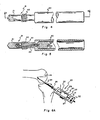
- the tunnel 18 is of a diameter to just accommodate a self-tapping suture anchor stud 19, that is also known as an isometric testing stud; hereinafter referred to as stud, and driver 20, shown in Figs. 4 and 5.
- a self-tapping suture anchor stud 19 that is also known as an isometric testing stud; hereinafter referred to as stud, and driver 20, shown in Figs. 4 and 5.
- the stud 19 is mounted on the end of driver 20 and passed into the tunnel.
- the surgeon guides the stud and driver by observing the fluoroscopic monitor 17 to where a stud drill 21 pointed end engages the femur at what the surgeon believes to be the femoral isometric point of origin.
- the stud 19 is then carefully turned into the bone, until medial self-tapping screws 22 that follow the drill end are fully turned into the bone, the stud rearmost end 23 coming to rest proximate to or aligned with the bone surface.
- suture a double strand radio-opaque flexible suture 24, hereinafter referred to as suture, extending therefrom.
- suture which suture is connected on its end and extending from the stud rearmost end 23.
- the suture 24 is thereby pulled from the driver to without the tibial tunnel 19.
- the suture 24 is to function as a mock anterior cruciate ligament for verifying that the selected tibial and femoral points of origin are isometrically correct.
- the mock ligament or suture 24 end is connected, under appropriate tension, to a tension isometer, as shown in Figs. 6A and 6B.
- a tension isometer With a certain preload on the scale of the tension isometer the knee is flexed through appropriate angular configurations and the exerted forces at the various knee attitudes are measured.
- For correct isometry there will be no more than a three (3) pound change in force and no more than a two (2) mm change in suture length or distance between the tibial and femoral points of origin, through a full range of knee motion.
- FIGS. 6A and 6B show a tension isometer 25 as including a tilting collar 26 that is for putting against the tibial tunnel entrance and wherethrough suture 24 is fitted and attached to a block 27.
- Block 17 is preferably arranged to travel within a housing 28 of the isometer. Housing 28 is open at one face to expose the block with sequential numbering 29 scribed along the housing face adjacent to the one edge of block 27, with a pointer 30 scribed on the adjacent block 27 edge, at its approximate mid-point.
- the pointer 30 is to point to a number 29 to indicate a force that is being applied on the block that is in opposition to a spring biasing acting on the block, not shown.
- the block 27 position or force applied thereto can further be preset to a certain force by operation of a set screw arrangement consisting of a threaded rod 31 that is turned through a caged manually turnable collar 32.
- the end of threaded rod 31 to butt against a block 27 and the suture is shown tied through a ring 33 on the opposite block end to pull that block against its spring biasing, as reflected by the positioning of pointer 30 relative to the scale 29. So arranged, as the tension on suture 24 is increased and decreased during knee movement through its full range of motion, that change is reflected as a greater or lesser force relative to the pre-set value or force on the tension isometer.
- Fig. 6A In practice, as illustrated in Fig. 6A, with the knee maintained at approximately a ninety (90) degree angle, the suture is attached under tension to the tension isometer 25, as set out above. The knee is then flexed through its full range of motion, to include a full extension as shown in Fig. 6B. During that knee flexure forces exerted on suture 24 are displayed on the tension isometer 25 as a change in position of pointer 30 relative to scale 29. For a correct selection of femoral and tibial points of origin, there will be no more than a three (3) pound change in force and no more than a two (2) mm change in ligament length or the distance between the points of origin throughout a full range of knee motion.
- a missed selection of one or both points of origin will show up as a much larger force differential.
- a large force and progressive elongation of the mock ligament occurred to a flexion of approximately ninety (90) degrees whereat an added or differential force of twenty five (25) pounds of tension was recorded and the mock ligament failed.
- test or trial points of origin and attaching the stud 19 with sutures 24 extending therebetween, as a mock ligament enables a reliable and precise test of isometry before the ligament tunnel is formed. Accordingly, it is desirable that the initial tibial tunnel and femoral site wherein the stud 19 is turned be as narrow as possible. So arranged, where an erroneous point of origin is selected, the test will be minimally invasive facilitating a re-selection of another femoral point or even a redrilling of the tibial tunnel 18 without an appreciable weakening of the bone integrity.
- the tibial tunnel 18 can be enlarged and a tandem femoral tunnel formed, as shown in Fig. 7.
- the femoral cortex at 35 is then tapped, the tandem tunnels to receive the ligament.
- Fig. 8 shows an allograft ligament 36 that has been rolled around a driver 37 and sutured and includes a threaded fitting 38 secured to the ligament end that has been turned in the tapped cortex 35, securing the one allograft ligament 36 end thereto.
- the other allograft ligament 36 end is secured to the tibia cortex as with a staple or staples, not shown, after the handle 37 has been pulled out from the ligament roll and a desired tension force applied to that ligament.
- a staple or staples not shown
- other arrangements of biologic grafts or prosthetic ligaments can be utilized as can other arrangements for securing them under tension, within the scope of this disclosure.
- the described procedure and components are applicable to a surgical replacement of the posterior cruciate ligament allowing, of course, for different tunnel forming as are appropriate for a posterior cruciate ligament replacement.
- the present invention is also directed to another embodiment of an isometric testing stud 40 shown in Figs. 9 and 9A and to a still another embodiment of an isometric testing stud 50, shown in Fig. 10 and 10A.
- Fig. 9 shows the isometric testing stud 40, hereinafter referred to as stud, that is substantially like the stud 19 of Figs. 4 and 5.
- stud 40 includes a fluted drill end 41 and medial cutting threads 42.
- stud 40 includes a hex-shaped rear end 43 that is to receive a driver, not shown, fitted thereover, the stud 40 and driver to otherwise function as does the driver 20 with stud 19 of Figs. 4 and 5.
- stud 40 at its hex end, to accommodate a wire suture 44, is drilled longitudinally at 45, as shown in Fig. 9A, and includes a lateral hole 46 that is shown in broken lines in Fig.
- the lateral hole 46 is shown at 47 sloped towards the fluted drill end 41, which slope is to guide the suture wire end 44a into and through longitudinal hole 45.
- the wire suture 44 is further shown in broken lines to include a bead 48 that is formed on its other end that is of greater diameter than the longitudinal hole 45. So arranged, the wire suture 44 is fitted through the longitudinal hole 45 to the bead 48 end that butts against the edge of longitudinal hole 45, blocking travel therethrough. The wire suture 44 is thereby fixed to the stud 40 and is, in turn, fitted longitudinally through the driver, not shown, to function like the suture 24 described as a mock ligament.
- Figs. 10 and 10A show still another embodiment of an isometric testing stud 50, hereinafter referred to as stud.
- Stud 50 like the above-described studs 19 and 40 is for implanting, by the above-described process, at a designated femoral or tibial point of ligament origin, with a suture extending therefrom that serves as a mock ligament for connection to a tension isometer.
- stud 50 does not include a drill end and in use, a hole must be formed into the bone surface of a diameter and depth to where the stud screw threads 51 will turn in that formed hole.
- stud 50 includes the threads 51 formed therearound over its entire length from a tapered nose end 52. Shown in Fig. 10, the stud nose end 52 tapers outwardly from a first tooth starting edge 53 that, when the stud is turned into a hole formed into a bone surface, will bite into that bone surface, the teeth 51 turning also into that bone.
- the stud 50 is holed longitudinally from end to end at 54, which hole 54, at a rearmost end, is enlarge to hve hexagonal shaped walls 55.
- the hexagon shaped opening walls 5 are to receive a hexagonal end 59 of a driver 58.
- the longitudinal hole 54 is to accommodate a suture, either fabric or wire fitted therethrough.
- the suture that is preferably wire 56 is fitted through hole 54 and through a longitudinal center passage 60, shown in broken lines, through driver 50 and includes a button 57 secured across the wire end.
- the button 57 has a diameter that is greater than the diameter of the longitudinal hole 54, prohibiting the withdrawal of the suture wire 56 therethrough.
- the tandem tibial and/or femoral tunnels for testing for proper ligament isometry are preferably as narrow a diameter as practical.
- a small diameter of tool is achieved.
- the driver end is fitted into the stud an even smaller diameter of driver can be utilized.
- studs 40 and 50 have been constructed to have, respectively, diameters of from 1/8 inch for stud 40, and 1/4 inch for stud 50. Stud 40, of course, requires a driver of greater diameter to fit over the hexagonal end 43 thereof.
Abstract
For knee reconstruction surgery involving replacement of an anterior or posterior cruciate ligament the present invention is in a process for verifying isometric ligament positioning at the femoral and tibial points of origin that includes, as apparatus, an arrangement of a stud (19) with attached suture (24) to serve as a mock ligament for testing isometry. In practice, as for an anterior cruciate ligament replacement procedure, a surgeon, observing on a fluoroscopic monitor (17), forms a tibial tunnel (18) from a point medial to the tibial tuberosity that exits a test or proposed tibial point of ligament origin. The stud (19) is arranged for turning on a driver (20) that is then passed through that formed tunnel and the stud (19) is turned into the test or proposed femoral point of ligament origin. The driver (20) is then pulled out of engagement with the stud (19) exposing the suture (24) that extends from that stud (19), which suture (24) is attached under tension to a tension isometer (25), and the knee (10) is flexed through its full range of motion. With an isometrically correct selection of the femoral and tibial ligament points of origin, the tension isometer (25) will show no more than a three (3) pound change in force and no more than a two (2) mm change in ligament length or distance between the two points of origin over a full range of knee (10) flexure.
Description
- The present invention relates to arthroscopic surgical procedures for ligament reconstruction and particularly to apparatus and a procedure for isometrically locating either an anterior or posterior cruciate ligament femoral and tibial points of attachment.
- In anterior and posterior ligament replacement surgery both ligament tension and positioning of that ligament between tibial and femoral surfaces must be optimumized for a successful surgery. Prior to the present invention such positioning involved a surgeon utilizing a fluoroscopic monitor or visually forming a tunnel to pass through the approximate ruptured ligament tibial and femoral points of origin, and attaching a ligament therein to test for correct isometry. An example of such procedure is shown in a patent to Daniel, et al., U.S. Patent No. 4,712,542. If the ligament positioning was found not to be isometrically correct the tunnel had to be altered or reformed until correct isometry was obtained. Essentially, a trial and error procedure with the surgeon's skill determining the outcome.
- Unlike the trial and error process set out above, the present invention provides a process for testing femoral and tibial ligament origin points that is both accurate and minimally invasive. The procedure further utilizes a mock ligament and a tension isometer to measure, when the knee is flexed through a full range of motion, a change in tension of no more than a certain force verifying proper isometric selection of the femoral and tibial points of origin.
- It is a principal object of the present invention to provide apparatus and a surgical procedure for knee ligament replacement surgery for determining optimum femoral and tibial anterior and/or posterior cruciate ligament points of origin whereafter a surgeon can form finished femoral and tibial tunnels through those points and maintain a ligament under tension therein.
- Another object of the present invention is to provide, as apparatus for performing the surgical procedure, an isometric testing stud, with attached suture for use as a mock ligament, for turning into a bone surface at a test posterior or anterior point of origin, the suture to extend therefrom through a tunnel in the opposite bone that has, as its one end, the other test point or origin, the suture free end to fit through the tunnel for connectin to a tension isometer for measuring applied tension at different knee positions.
- Still another object of the present invention is to provide apparatus and process for locating the isometric tibial and femoral points of origin on the opposing bone surface for an interior or posterior cruciate ligament that is performed fluoroarthroscopically and is minimally invasive
- The present invention is an apparatus and procedure for locating and testing for proper isometry test points of origin for a cruciate ligament. With the test points located, a tunnel that consists of aligned or divergent tunnel segments formed through the respective distal femoral and proximal tibial bone ends, intersecting the points of origin. In practice, once the proper tunnels through points of origin are properly formed to receive the ligament, with one end of the ligament secured in place, a desired tension is applied to the other ligament end, and that end is then secured in place. Assuming that the ligament is properly aligned through the correct ligament points of origin, this tensioning is routine.
- It is, therefore, the locating of the ligament points of origin on the femoral and tibial surfaces that is critical to the success of the procedure. Through experimentation, for replacement of the anterior cruciate ligament, it has been determined that the femoral origin will be approximately three (3) mm anterior to the junction of the posterior cortex and the intercondylar seam; with the site of the tibial origin at a point that is approximately one third of (1/3) the anteroposterior distance posterior to the anterior tibia, or approximately eighteen (18) to twenty two (22) mm posterior to the front of the bony tibia. In the replacement of a posterior cruciate ligament the tibial point of origin has been determined to be at the posterior margin of the mid-portion of the tibial plateau and the femoral point of origin is located within the intercondylar notch at varying points in the medial femoral condyle. These are the approximate points that a tunnel needs to pass through to provide for proper replacement of an anterior or posterior cruciate ligament with either a biologic graft or prosthetic ligament.
- For performing this procedure the present invention preferably employs an isometric testing stud with attached suture that may be like the self-drilling and tapping titanium metal stud shown in a U.S. Patent No. 4,632,100 that the present inventors are the inventors of. Though, it should be understood, other arrangements of isometric testing studs with radio-opaque fabric, or metal sutures, or the like, can be used for the described procedure.
- For replacement of an anterior cruciate ligament the isometric testing stud is inserted through a medial parapatellar arthroscopy tunnel or portal that is passed through the test or intended tibial point of origin. Which isometric testing stud is turned by a driver into the test femoral point of ligament origin. The driver is then removed by pulling it back through the tunnel. In that driver removal, which is contained in the driver and attached on one end of the stud, is thereby pulled from the driver as the driver is removed from the tunnel or portal. The suture free end is then attached under tension to a tension isometer. To test for proper isometry, the patient's knee is flexed appropriately through its full range of motion, with differences in tension shown on the tension isometer. If there is less than a three (3) pound change in tension over the full range of knee motion the selected test femoral and tibial point of origin are confirmed as being correct.
- When correct femoral and tibial point of origin selection is verified the isometric testing stud is turned out of the bone and the knee is drilled with successively larger drills until a tunnel of sufficient diameter to accommodate a replacement ligament is available. One ligament end is secured within a cortex tunnel end and the other end of the ligament is secured to the bone surface. A U.S. Patent No. 4,772,286 that the present inventors are the inventors of show a process for attaching an anterior cruciate ligament within such tandem tunnels in knee reconstruction surgery.
- These and other objects and features of the present invention will become more fully apparent from the following description in which the invention is described in detail in conjunction with the accompanying drawings.
- Fig. 1 is a side elevation view of the distal femur and proximal tibia bone ends showing a longitudinal section of the distal femur removed to the intercondylar notch, and showing a "K" wire inserted from the anterior medial tibia through the anterior cruciate ligament, to illustrate the femoral and tibia points of ligament origin;
- Fig. 2 is a side elevation view of a patient's leg, the knee shown flexed at approximately a ninety (90) degree angle with a vertical line above the tibial tuberosity shown in broken lines;
- Fig. 3 is a side elevation view of a surgeon observing a monitor and positioned in front of the knee of Fig. 2, drilling a tunnel from the tibial tuberosity that is shown on the monitor exiting the ligament tibial origin;
- Fig. 4 shows a side elevation view of a suture anchor for use as an isometric testing stud with driver therefore;
- Fig. 5 shows a sectional view taken along the line 5-5 of Fig. 4;
- Fig. 6A shows the knee of Figs. 2 and 3 with the suture anchor of Fig. 4 fitted through the tibial tunnel of Fig. 3 and turned into the femur at the ligament femoral origin, the suture thereof shown connected to a tension isometer;
- Fig. 6B shows the knee of Fig. 6A in a straightened attitude;
- Fig. 7 shows the knee of Figs. 2 and 3 after aligned tunnels have been drilled through the femoral and tibial ligament origins and femur cortex to receive a ligament installed therein;
- Fig. 8 shows an allograft ligament mounted to a driver being installed in the tandem tunnels of Fig. 7, with a threaded connector shown attached to the ligament end for turning in a tapped hole formed in the femur cortex;
- Fig. 9 is a side elevation view of another embodiment of an isometric testing stud that includes a suture wire for use as a mock ligament in practicing the process of the present invention;
- Fig. 9A is a rear end view of the isometric testing stud of Fig. 9;
- Fig. 10 is a side elevation view of still another embodiment of an isometric testing stud for use as a mock ligament in practicing the process of the present invention;
- Fig. 10A is a rear end view of the isometric testing stud of Fig. 10; and
- Fig. 11 is a side elevation view of a driver for coupling at a hexagonal shaped end thereof into the isometric testing stud of Figs. 10 and 10A, and showing, in broken lines, a longitudinal cavity formed therethrough.
- In knee reconstruction surgery it is recognized that the surgical procedure should be minimally invasive and yet be adequate to accomplish the goal to accurately re-establish the patient's four bar chain-like system. To this end the surgical entrance should be of minimal size to avoid unnecessary pain, poor cosmoses, and loss of normal joint proprioception. Further, the procedure should be performed in minimal time to limit tourniquet application time. The present procedure addresses and meets these needs and considerations.
- Fig. 1 is included to illustrate that an optimum ligament replacement of an anterior cruciate ligament in
knee 10 involves exactly connecting the replacement ligament, either a biological graft or prosthetic, at the femoral and tibial points of origin. This is illustrated by the arrangement of a pin or drill 11 that is shown passed through the ligament and its points of origin. Unfortunately, a ligament rupture necessitating the procedure may involve a separation of the ligament end from the bone surface making it difficult or impossible to determine a point of origin, particularly when that point of origin must be determined viewing a fluoroscopic monitor. - Human cadaveric dissections have revealed the precise points of attachment as are necessary to achieve a "check rein" replacement for a deficient anterior cruciate ligament. Experimentally, as viewed from a lateral knee radiograph, the isometric anterior cruciate ligament femoral origin is at a point that is approximately three (3) mm anterior to the junction of the posterior cortex and the intercondylar seam, with the site of the isometric tibial insertion located at a point that is approximately one third (1/3) of the anteroposterior distance posterior to the anterior tibia, or approximately eighteen (18) to twenty two (22) mm posterior to the front of the bony tibia. These insertion points are, as shown in Fig. 1, for the anterior cruciate ligament. For the posterior cruciate ligament the points of origin are similarly determined and, it should be understood, the present process is applicable to both cruciate ligament replacement. Of course, the points of origin and tunnels are appropriately selected and formed for the particular cruciate ligament being replaced.
- In Fig. 2 the
knee 10 is shown in broken lines. Therein, a verticalbroken line 12 located alongside a surgeon'sthumb 13 marks a point above the tibial tuberosity that is the target for forming the tibial tunnel, as shown in Fig. 3. In Fig. 3 a surgeon 14, seated in from ofknee 10 that is flexed to approximately one hundred ten (110) degrees, operates adrill 15 as he observes on a fluoroscopic monitor 17 drill end 16 progress intoknee 10. Shown on the fluoroscopic monitor 17, the drill end 16 has passed into a medial point on the anterior tibial tuberosity and exits the test tibial point of origin of the anterior cruciate ligament formingtibial tunnel 18. Which tunnel exiting the test tibial point of origin is directly opposite to the test femoral point of origin of the ligament. Thetunnel 18 is of a diameter to just accommodate a self-tappingsuture anchor stud 19, that is also known as an isometric testing stud; hereinafter referred to as stud, anddriver 20, shown in Figs. 4 and 5. - To locate the test of trial tibial and femoral points of origin, with the
tibial tunnel 18 formed as set out above, thestud 19 is mounted on the end ofdriver 20 and passed into the tunnel. The surgeon guides the stud and driver by observing the fluoroscopic monitor 17 to where a stud drill 21 pointed end engages the femur at what the surgeon believes to be the femoral isometric point of origin. Thestud 19 is then carefully turned into the bone, until medial self-tappingscrews 22 that follow the drill end are fully turned into the bone, the studrearmost end 23 coming to rest proximate to or aligned with the bone surface. Thereafter, thedriver 20 is pulled out from engagement within thestud 19, leaving a double strand radio-opaqueflexible suture 24, hereinafter referred to as suture, extending therefrom. Which suture is connected on its end and extending from the studrearmost end 23. Thesuture 24 is thereby pulled from the driver to without thetibial tunnel 19. Thesuture 24 is to function as a mock anterior cruciate ligament for verifying that the selected tibial and femoral points of origin are isometrically correct. - To determine that the
tibia tunnel 18 end and selected femoral point are the true isometric points, the mock ligament orsuture 24 end is connected, under appropriate tension, to a tension isometer, as shown in Figs. 6A and 6B. With a certain preload on the scale of the tension isometer the knee is flexed through appropriate angular configurations and the exerted forces at the various knee attitudes are measured. For correct isometry there will be no more than a three (3) pound change in force and no more than a two (2) mm change in suture length or distance between the tibial and femoral points of origin, through a full range of knee motion. For example, Figs. 6A and 6B show atension isometer 25 as including atilting collar 26 that is for putting against the tibial tunnel entrance andwherethrough suture 24 is fitted and attached to ablock 27. Block 17 is preferably arranged to travel within ahousing 28 of the isometer.Housing 28 is open at one face to expose the block withsequential numbering 29 scribed along the housing face adjacent to the one edge ofblock 27, with apointer 30 scribed on theadjacent block 27 edge, at its approximate mid-point. Thepointer 30 is to point to anumber 29 to indicate a force that is being applied on the block that is in opposition to a spring biasing acting on the block, not shown. Theblock 27 position or force applied thereto can further be preset to a certain force by operation of a set screw arrangement consisting of a threadedrod 31 that is turned through a caged manuallyturnable collar 32. The end of threadedrod 31 to butt against ablock 27 and the suture is shown tied through aring 33 on the opposite block end to pull that block against its spring biasing, as reflected by the positioning ofpointer 30 relative to thescale 29. So arranged, as the tension onsuture 24 is increased and decreased during knee movement through its full range of motion, that change is reflected as a greater or lesser force relative to the pre-set value or force on the tension isometer. - In practice, as illustrated in Fig. 6A, with the knee maintained at approximately a ninety (90) degree angle, the suture is attached under tension to the
tension isometer 25, as set out above. The knee is then flexed through its full range of motion, to include a full extension as shown in Fig. 6B. During that knee flexure forces exerted onsuture 24 are displayed on thetension isometer 25 as a change in position ofpointer 30 relative toscale 29. For a correct selection of femoral and tibial points of origin, there will be no more than a three (3) pound change in force and no more than a two (2) mm change in ligament length or the distance between the points of origin throughout a full range of knee motion. A missed selection of one or both points of origin will show up as a much larger force differential. For example, in a cadaver study, where the femoral origin was placed just three (3) mm anterior to the desired isometric point, in full extension a large force and progressive elongation of the mock ligament occurred to a flexion of approximately ninety (90) degrees whereat an added or differential force of twenty five (25) pounds of tension was recorded and the mock ligament failed. - Also, of course, where the ligament undergoes laxity, such is also unacceptable. Accordingly, a femoral origin placement where the placement is passed or "over the top" of the isometric point was found to result in progressive anterior laxity in flexion. Experimentally, with a pre-load of ten (10) pounds at ninety (90) degrees flexion, there was no force shown on the tension isometer, with laxity further progressing as the knee was flexed to one hundred forty (140) degrees.
- As set out above, locating test or trial points of origin and attaching the
stud 19 withsutures 24 extending therebetween, as a mock ligament, enables a reliable and precise test of isometry before the ligament tunnel is formed. Accordingly, it is desirable that the initial tibial tunnel and femoral site wherein thestud 19 is turned be as narrow as possible. So arranged, where an erroneous point of origin is selected, the test will be minimally invasive facilitating a re-selection of another femoral point or even a redrilling of thetibial tunnel 18 without an appreciable weakening of the bone integrity. With the femoral and tibial isometric points determined thetibial tunnel 18 can be enlarged and a tandem femoral tunnel formed, as shown in Fig. 7. The femoral cortex at 35 is then tapped, the tandem tunnels to receive the ligament. - Fig. 8 shows an
allograft ligament 36 that has been rolled around a driver 37 and sutured and includes a threadedfitting 38 secured to the ligament end that has been turned in the tappedcortex 35, securing the oneallograft ligament 36 end thereto. Theother allograft ligament 36 end is secured to the tibia cortex as with a staple or staples, not shown, after the handle 37 has been pulled out from the ligament roll and a desired tension force applied to that ligament. Of course, other arrangements of biologic grafts or prosthetic ligaments can be utilized as can other arrangements for securing them under tension, within the scope of this disclosure. Further, it should be understood, the described procedure and components are applicable to a surgical replacement of the posterior cruciate ligament allowing, of course, for different tunnel forming as are appropriate for a posterior cruciate ligament replacement. - Where the
stud 19 has been found in practice to be usable as a mock ligament, it is recognized that another configuration of a isometric testing stud and driver than those shown in Figs. 4 and 5 could also be used. Accordingly, the present invention is also directed to another embodiment of anisometric testing stud 40 shown in Figs. 9 and 9A and to a still another embodiment of anisometric testing stud 50, shown in Fig. 10 and 10A. - Fig. 9 shows the
isometric testing stud 40, hereinafter referred to as stud, that is substantially like thestud 19 of Figs. 4 and 5. Likestud 19,stud 40 includes afluted drill end 41 and medial cutting threads 42. Distinct from thestud 19,stud 40 includes a hex-shapedrear end 43 that is to receive a driver, not shown, fitted thereover, thestud 40 and driver to otherwise function as does thedriver 20 withstud 19 of Figs. 4 and 5. Further distinct fromstud 19,stud 40, at its hex end, to accommodate awire suture 44, is drilled longitudinally at 45, as shown in Fig. 9A, and includes alateral hole 46 that is shown in broken lines in Fig. 9, intersecting thatlongitudinally hole 45. Thelateral hole 46 is shown at 47 sloped towards thefluted drill end 41, which slope is to guide the suture wire end 44a into and throughlongitudinal hole 45. Thewire suture 44 is further shown in broken lines to include abead 48 that is formed on its other end that is of greater diameter than thelongitudinal hole 45. So arranged, thewire suture 44 is fitted through thelongitudinal hole 45 to thebead 48 end that butts against the edge oflongitudinal hole 45, blocking travel therethrough. Thewire suture 44 is thereby fixed to thestud 40 and is, in turn, fitted longitudinally through the driver, not shown, to function like thesuture 24 described as a mock ligament. - Figs. 10 and 10A show still another embodiment of an
isometric testing stud 50, hereinafter referred to as stud.Stud 50, like the above-describedstuds studs stud 50 does not include a drill end and in use, a hole must be formed into the bone surface of a diameter and depth to where thestud screw threads 51 will turn in that formed hole. Preferably,stud 50 includes thethreads 51 formed therearound over its entire length from a taperednose end 52. Shown in Fig. 10, the stud nose end 52 tapers outwardly from a firsttooth starting edge 53 that, when the stud is turned into a hole formed into a bone surface, will bite into that bone surface, theteeth 51 turning also into that bone. - Shown in broken lines in Fig. 10, the
stud 50 is holed longitudinally from end to end at 54, which hole 54, at a rearmost end, is enlarge to hve hexagonal shapedwalls 55. The hexagon shaped opening walls 5 are to receive a hexagonal end 59 of adriver 58. Shown in Fig. 11, for guiding the stud on the end thereof through a prepared femoral or tibial tunnel and into the hole formed in the opposing bone surface for turning therein. From the hexagonalwalled end 55 the longitudinal hole 54 is to accommodate a suture, either fabric or wire fitted therethrough. As shown in Fig. 10, the suture that is preferably wire 56, is fitted through hole 54 and through alongitudinal center passage 60, shown in broken lines, throughdriver 50 and includes abutton 57 secured across the wire end. Thebutton 57 has a diameter that is greater than the diameter of the longitudinal hole 54, prohibiting the withdrawal of the suture wire 56 therethrough. - As set out above, the tandem tibial and/or femoral tunnels for testing for proper ligament isometry are preferably as narrow a diameter as practical. With the suture attaching arrangements of
studs stud 50, the driver end is fitted into the stud an even smaller diameter of driver can be utilized. In practice,studs stud 40, and 1/4 inch forstud 50.Stud 40, of course, requires a driver of greater diameter to fit over thehexagonal end 43 thereof. - While a preferred embodiment of a process and embodiments of apparatus for practicing that process have been shown and described herein, it should be apparent that the present disclosure is made by way of example only and that variations are possible within the scope of this disclosure without departing from the subject matter coming within the scope of the following claims, which claims we regard as our invention.
Claims (17)
1. Apparatus for verifying isometric ligament positioning in an arthroscopic surgical procedure for replacing a knee anterior or posterior cruciate ligament, where a surgeon operates observing the procedure on a fluoroscopic monitor, by forming a tunnel from the cortex through the femur or tibia, exiting a first test ligament point of origin, the tunnel aligning with the other test or second ligament point of origin comprising, an isometric testing stud means having a cylindrical body with means for attaching a suture means thereto and is arranged to be inserted through a tunnel and to be turned by a removable driver means, said isometric testing stud further including thread means formed around the outer circumference for turning into bone; a removable driver means arranged to fit over or into for turning said isometric testing stud body; suture means secured to said isometric testing stud means to extend through said removable driver means to be pulled therefrom as said removable driver means is pulled out of engagement with said isometric testing stud; and a tension isometer means that receives said suture attached thereto under tension for recording changes in tensile force as the knee is flexed through its full range of motion.
2. Apparatus as recited in Claim 1, wherein the isometric testing stud incorporates a fluted drill forward of the thread means.
3. Apparatus as recited in Claim 1, wherein the means for attaching a suture means is a longitudinal hole formed in the driver engaging end of the isometric testing stud body to receive a suture fitted therein; and means for maintaining said suture end within said longitudinal hole.
4. Apparatus as recited in Claim 3, wherein the suture is a metal wire that includes a bead secured across an end thereof, which bead has a diameter that is greater than the longitudinal hole; and a lateral hole formed through the isometric testing stud body to intersect said longitudinal hole, said lateral hole to receive said suture wire passed therethrough and through said longitudinal hole;
5. Apparatus as recited in Claim 1, wherein the removable driver means includes a longitudinal passage therethrough and includes intersecting internal or external sides formed around one end for fitting into or over a complimentary sided end surface of the isometric testing stud body.
6. Apparatus as recited in Claim 1, wherein the thread means are formed along the length of the isometric testing stud body, which body has a center longitudinal passage formed therethrough, with a rearmost end of which passage enlarged into a side section for accommodating a complimentary end of the removable driver means fitted therein.
7. Apparatus as recited in Claim 6, wherein the isometric testing stud body tapers outwardly at a forward end form the center opening to approximately a mid-point; and the first flight of threads includes a cutting edge means for turning into a bone material.
8. A process to verify proper isometric ligament positioning in an arthroscopic surgical procedure on a human knee to replace the anterior or posterior cruciate ligament as performed by a surgeon viewing a fluoroscopic monitor, comprising the steps of, with a patient's knee maintained appropriately forming a test passage from a point on the anterior medial portion of the tibia for an anterior cruciate ligament replacement or of the femur for a posterior cruciate ligament replacement, through the bone to intersect and pass through a first proposed or test ligament point of origin; guiding an isometric testing stud mounted to the end of a driver through the passage and turning a drill end thereof followed by a threaded portion of which isometric testing stud into the bone at a second proposed or test ligament point of origin on the femur for an anterior cruciate ligament replacement or on the tibia for a posterior cruciate ligament replacement; pulling the driver out of engagement with the isometric testing stud and withdrawing said driver out of said test passage exposing a suture connected to the exposed end of said isometric testing stud; connecting, under tension, said exposed portion of said suture to a tension isometer that will read a load condition on said suture; flexing the knee through its full range of motion; and observing the tension isometer during the knee flexure, where providing the proposed or test points of origin are isometrically correct, there will be no more than a three (3) pound change in tension on said suture.
9. A process as recited in Claim 8, wherein through a full range of knee flexure there will be no more than a two (2) mm change in the suture length of distance between the test points of origin for an isometrically correct selection of points of origin.
10. A isometric testing stud comprising, a cylindrical body that includes circumferential threads, a longitudinal hole formed in a rear end thereof and includes means for receiving a driver means end fitted therethrough for turning; a suture; button means for arrangement to said suture, extending thereacross, which button means is of greater diameter than said longitudinal hole; and means for installing said suture through said longitudinal hole, said button means prohibiting withdrawal of said suture through said longitudinal hole.
11. An isometric testing stud as recited in Claim 10, wherein the suture is a wire.
12. An isometric testing stud as recited in Claim 10, further including a fluted drill arranged as the forward end of the cylindrical body followed by the circumferential threads around the cylindrical body mid-section; and the means for installing said future through said longitudinal hole is a lateral hole formed in said cylindrical body to intersect said longitudinal hole that is of greater diameter than said longitudinal hole.
13. An isometric testing stud as recited in Claim 12, wherein the lateral hole is sloped away from said longitudinal hole.
14. An isometric testing stud as recited in Claim 12, wherein the means for receiving a driver means are hexagon sides formed around the cylindrical body rear end.
15. An isometric testing stud as recited in Claim 10, wherein the circumferential threads are formed around the entire cylindrical body, a leading or first flight of threads arranged to cut into the side of a hole formed into a bone.
16. An isometric testing stud as recited in Claim 15, wherein the longitudinal hole is formed through the cylindrical body, which cylindrical body is flat on a forward end to accommodate the button thereover, and tapers outwardly from that flat portion.
17. An isometric testing stud as recited in Claim 15, wherein the longitudinal hole at the rear end of the cylindrical body is enlarged into a hexagonal shaped sided cavity.
Applications Claiming Priority (2)
| Application Number | Priority Date | Filing Date | Title |
|---|---|---|---|
| US07/246,324 US5037426A (en) | 1988-09-19 | 1988-09-19 | Procedure for verifying isometric ligament positioning |
| US246324 | 1988-09-19 |
Publications (1)
| Publication Number | Publication Date |
|---|---|
| EP0361756A1 true EP0361756A1 (en) | 1990-04-04 |
Family
ID=22930194
Family Applications (1)
| Application Number | Title | Priority Date | Filing Date |
|---|---|---|---|
| EP89309489A Withdrawn EP0361756A1 (en) | 1988-09-19 | 1989-09-19 | Apparatus and procedure for verifying isometric ligament positioning |
Country Status (5)
| Country | Link |
|---|---|
| US (2) | US5037426A (en) |
| EP (1) | EP0361756A1 (en) |
| JP (1) | JPH02109551A (en) |
| AU (1) | AU619043B2 (en) |
| CA (1) | CA1320404C (en) |
Cited By (14)
| Publication number | Priority date | Publication date | Assignee | Title |
|---|---|---|---|---|
| EP0440991A1 (en) * | 1990-01-31 | 1991-08-14 | Acufex Microsurgical Inc. | Method and instruments for the reconstruction of the anterior cruciate ligament |
| EP0465910A1 (en) * | 1990-07-13 | 1992-01-15 | American Cyanamid Company | Improved suture anchor and driver assembly |
| EP0686373A1 (en) * | 1994-06-09 | 1995-12-13 | Bristol-Myers Squibb Company | Suture anchor |
| FR2720921A1 (en) * | 1994-06-09 | 1995-12-15 | Vergnolle Jean Pierre | Instrument for determining isometric point of knee joint |
| WO1996009797A1 (en) * | 1994-09-28 | 1996-04-04 | Innovasive Devices, Inc. | Suture tensioning device |
| WO1996041573A1 (en) * | 1995-06-13 | 1996-12-27 | Synthes Ag Chur | Self-drilling bone securing component |
| DE19814564C1 (en) * | 1998-04-01 | 2000-01-27 | Aesculap Ag & Co Kg | Hand implement for attaching caps to bone channels |
| WO2004069099A1 (en) * | 2003-02-06 | 2004-08-19 | Nihon University | Tension probe for ligament |
| WO2006113948A2 (en) * | 2005-04-27 | 2006-11-02 | Austria Wirtschaftsservice Gesellschaft mit beschränkter Haftung | Device and method for measuring the tensile force acting upon two body parts |
| WO2011116208A1 (en) * | 2010-03-18 | 2011-09-22 | Smith & Nephew, Inc. | A device for use during ligament reconstruction surgery |
| WO2012026915A1 (en) * | 2010-08-23 | 2012-03-01 | Ebi, Llc | Driver-screw retention mechanism |
| US8444652B2 (en) | 2006-03-23 | 2013-05-21 | Imperial Innovations Ltd. | Reconstruction of anterior cruciate ligaments |
| US9386997B2 (en) | 2013-03-29 | 2016-07-12 | Smith & Nephew, Inc. | Tunnel gage |
| USD819432S1 (en) | 2014-03-11 | 2018-06-05 | Ziptek LLC. | Screw |
Families Citing this family (147)
| Publication number | Priority date | Publication date | Assignee | Title |
|---|---|---|---|---|
| US5366457A (en) * | 1991-12-13 | 1994-11-22 | David A. McGuire | Method and apparatus for preparing a bone and tendon graft |
| US5520693A (en) * | 1992-02-19 | 1996-05-28 | Mcguire; David A. | Femoral guide and methods of precisely forming bone tunnels in cruciate ligament reconstruction of the knee |
| US5562664A (en) * | 1992-02-20 | 1996-10-08 | Arthrex Inc. | Drill guide with target PCL-oriented marking hook |
| US5269786A (en) * | 1992-02-20 | 1993-12-14 | Arthrex Inc. | PCL oriented placement tibial guide method |
| FR2699271B1 (en) * | 1992-12-15 | 1995-03-17 | Univ Joseph Fourier | Method for determining the femoral anchor point of a cruciate knee ligament. |
| US5507812A (en) * | 1992-12-28 | 1996-04-16 | Moore; David E. | Modular prosthetic ligament |
| US5431651A (en) * | 1993-02-08 | 1995-07-11 | Goble; E. Marlowe | Cross pin and set screw femoral and tibial fixation method |
| US5507750A (en) * | 1993-09-16 | 1996-04-16 | Goble; E. Marlowe | Method and apparatus for tensioning grafts or ligaments |
| US5527342A (en) | 1993-12-14 | 1996-06-18 | Pietrzak; William S. | Method and apparatus for securing soft tissues, tendons and ligaments to bone |
| US5417692A (en) * | 1994-01-04 | 1995-05-23 | Goble; E. Marlowe | Bone fixation and fusion system |
| US5601566A (en) * | 1994-02-22 | 1997-02-11 | Osteonics Corp. | Method and apparatus for the alignment of a femoral knee prosthesis |
| US5411523A (en) * | 1994-04-11 | 1995-05-02 | Mitek Surgical Products, Inc. | Suture anchor and driver combination |
| US5411506A (en) * | 1994-04-11 | 1995-05-02 | Mitek Surgical Products, Inc. | Anchor driver |
| US5645589A (en) * | 1994-08-22 | 1997-07-08 | Li Medical Technologies, Inc. | Anchor and method for securement into a bore |
| US5843127A (en) * | 1994-08-22 | 1998-12-01 | Le Medical Technologies, Inc. | Fixation device and method for installing same |
| US5611801A (en) * | 1994-11-29 | 1997-03-18 | Pioneer Laboratories, Inc. | Method and apparatus for bone fracture fixation |
| US5643320A (en) * | 1995-03-13 | 1997-07-01 | Depuy Inc. | Soft tissue anchor and method |
| US5702215A (en) * | 1995-06-05 | 1997-12-30 | Li Medical Technologies, Inc. | Retractable fixation device |
| US5643266A (en) * | 1995-06-05 | 1997-07-01 | Li Medical Technologies, Inc. | Method and apparatus for securing ligaments |
| US6117161A (en) * | 1995-06-06 | 2000-09-12 | Li Medical Tecnologies, Inc. | Fastener and fastening method, particularly for fastening sutures to bone |
| US5690649A (en) * | 1995-12-05 | 1997-11-25 | Li Medical Technologies, Inc. | Anchor and anchor installation tool and method |
| US5741300A (en) * | 1996-09-10 | 1998-04-21 | Li Medical Technologies, Inc. | Surgical anchor and package and cartridge for surgical anchor |
| US6264676B1 (en) | 1996-11-08 | 2001-07-24 | Scimed Life Systems, Inc. | Protective sheath for transvaginal anchor implantation devices |
| DE69734606T2 (en) | 1996-11-21 | 2006-08-03 | Ethicon, Inc. | DEVICE FOR FIXING BODY-FREE OR ARTIFICIAL TENANTS IN BONES |
| US8496705B2 (en) | 1996-11-21 | 2013-07-30 | DePuy Mitek, LLCR | Method of anchoring autologous or artificial tendon grafts in bone |
| US5707395A (en) * | 1997-01-16 | 1998-01-13 | Li Medical Technologies, Inc. | Surgical fastener and method and apparatus for ligament repair |
| US5713897A (en) * | 1997-03-06 | 1998-02-03 | Goble; E. Marlowe | Anterior cruciate ligament tensioning device and method for its use |
| US6001106A (en) * | 1997-09-03 | 1999-12-14 | M & R Medical, Inc. | System for tensioning ligament grafts |
| US5944724A (en) * | 1997-10-30 | 1999-08-31 | Mitek Surgical Products, Inc. | Suture anchor insertion system |
| US5968050A (en) * | 1997-12-05 | 1999-10-19 | Smith & Nephew, Inc. | Positioning a tibial tunnel |
| US6660010B2 (en) * | 1998-01-27 | 2003-12-09 | Scimed Life Systems, Inc. | Bone anchor placement device with recessed anchor mount |
| US6096041A (en) * | 1998-01-27 | 2000-08-01 | Scimed Life Systems, Inc. | Bone anchors for bone anchor implantation device |
| US6146406A (en) | 1998-02-12 | 2000-11-14 | Smith & Nephew, Inc. | Bone anchor |
| US6175760B1 (en) * | 1998-02-17 | 2001-01-16 | University Of Iowa Research Foundation | Lesion localizer for nuclear medicine |
| DE69916045T2 (en) | 1998-05-12 | 2004-08-05 | Boston Scientific Ltd., St. Michael | HAND-OPERATED BONE ANCHOR SETTING DEVICE |
| US6036694A (en) * | 1998-08-03 | 2000-03-14 | Innovasive Devices, Inc. | Self-tensioning soft tissue fixation device and method |
| WO2000054687A1 (en) * | 1999-03-17 | 2000-09-21 | Synthes Ag Chur | Imaging and planning device for ligament graft placement |
| US6132442A (en) * | 1999-03-25 | 2000-10-17 | Smith & Nephew | Graft clamp |
| US6599289B1 (en) | 2000-03-10 | 2003-07-29 | Smith & Nephew, Inc. | Graft anchor |
| GB0013037D0 (en) * | 2000-05-31 | 2000-07-19 | Atlantech Medical Devices Limi | Tension measuring device |
| US6679889B1 (en) * | 2000-11-13 | 2004-01-20 | Hs West Investments, Llc | Apparatus and methods for independently conditioning and pretensioning a plurality of ligament grafts during joint repair surgery |
| US20040153153A1 (en) * | 2001-05-31 | 2004-08-05 | Elson Robert J. | Anterior cruciate ligament reconstruction system and method of implementing same |
| US20050065533A1 (en) * | 2001-05-31 | 2005-03-24 | Magen Hugh E. | Apparatus for assembling anterior cruciate ligament reconstruction system |
| WO2003068090A1 (en) * | 2002-02-11 | 2003-08-21 | Smith & Nephew, Inc. | Image-guided fracture reduction |
| GB0208667D0 (en) | 2002-04-16 | 2002-05-29 | Atlantech Medical Devices Ltd | A transverse suspension device |
| US7319897B2 (en) * | 2002-12-02 | 2008-01-15 | Aesculap Ag & Co. Kg | Localization device display method and apparatus |
| JP3760920B2 (en) * | 2003-02-28 | 2006-03-29 | 株式会社デンソー | Sensor |
| US7686810B2 (en) * | 2003-08-29 | 2010-03-30 | Hs West Investments, Llc | Suture separation and organization devices for use with graft tensioning device |
| US20050049598A1 (en) * | 2003-08-29 | 2005-03-03 | West Hugh S. | Suture pulley for use with graft tensioning device |
| US7905924B2 (en) * | 2003-09-03 | 2011-03-15 | Ralph Richard White | Extracapsular surgical procedure |
| US7862570B2 (en) | 2003-10-03 | 2011-01-04 | Smith & Nephew, Inc. | Surgical positioners |
| US8162967B1 (en) | 2003-10-16 | 2012-04-24 | Biomet Sports Medicine Llc | Method and apparatus for coring and reaming of bone |
| US7764985B2 (en) | 2003-10-20 | 2010-07-27 | Smith & Nephew, Inc. | Surgical navigation system component fault interfaces and related processes |
| WO2005048851A1 (en) * | 2003-11-14 | 2005-06-02 | Smith & Nephew, Inc. | Adjustable surgical cutting systems |
| US7901404B2 (en) | 2004-01-16 | 2011-03-08 | Arthrocare Corporation | Bone harvesting device and method |
| JP2007523696A (en) * | 2004-01-16 | 2007-08-23 | スミス アンド ネフュー インコーポレーテッド | Computer-aided ligament balancing in total knee arthroplasty |
| EP1734884B1 (en) | 2004-03-16 | 2021-06-16 | Guidance Endodontics, LLC | Endodontic files |
| EP1729665A1 (en) | 2004-03-31 | 2006-12-13 | Smith and Nephew, Inc. | Methods and apparatuses for providing a reference array input device |
| WO2005104978A1 (en) | 2004-04-21 | 2005-11-10 | Smith & Nephew, Inc. | Computer-aided methods, systems, and apparatuses for shoulder arthroplasty |
| US7749268B2 (en) * | 2004-05-26 | 2010-07-06 | Warsaw Orthopedic, Inc. | Methods for treating the spine |
| US7905904B2 (en) | 2006-02-03 | 2011-03-15 | Biomet Sports Medicine, Llc | Soft tissue repair device and associated methods |
| US8303604B2 (en) | 2004-11-05 | 2012-11-06 | Biomet Sports Medicine, Llc | Soft tissue repair device and method |
| US8361113B2 (en) | 2006-02-03 | 2013-01-29 | Biomet Sports Medicine, Llc | Method and apparatus for coupling soft tissue to a bone |
| US8128658B2 (en) | 2004-11-05 | 2012-03-06 | Biomet Sports Medicine, Llc | Method and apparatus for coupling soft tissue to bone |
| US7909851B2 (en) | 2006-02-03 | 2011-03-22 | Biomet Sports Medicine, Llc | Soft tissue repair device and associated methods |
| US9017381B2 (en) | 2007-04-10 | 2015-04-28 | Biomet Sports Medicine, Llc | Adjustable knotless loops |
| US9801708B2 (en) | 2004-11-05 | 2017-10-31 | Biomet Sports Medicine, Llc | Method and apparatus for coupling soft tissue to a bone |
| US8088130B2 (en) | 2006-02-03 | 2012-01-03 | Biomet Sports Medicine, Llc | Method and apparatus for coupling soft tissue to a bone |
| US8840645B2 (en) | 2004-11-05 | 2014-09-23 | Biomet Sports Medicine, Llc | Method and apparatus for coupling soft tissue to a bone |
| US8298262B2 (en) | 2006-02-03 | 2012-10-30 | Biomet Sports Medicine, Llc | Method for tissue fixation |
| US7749250B2 (en) | 2006-02-03 | 2010-07-06 | Biomet Sports Medicine, Llc | Soft tissue repair assembly and associated method |
| US8118836B2 (en) | 2004-11-05 | 2012-02-21 | Biomet Sports Medicine, Llc | Method and apparatus for coupling soft tissue to a bone |
| US8137382B2 (en) | 2004-11-05 | 2012-03-20 | Biomet Sports Medicine, Llc | Method and apparatus for coupling anatomical features |
| US7658751B2 (en) | 2006-09-29 | 2010-02-09 | Biomet Sports Medicine, Llc | Method for implanting soft tissue |
| US8998949B2 (en) | 2004-11-09 | 2015-04-07 | Biomet Sports Medicine, Llc | Soft tissue conduit device |
| EP1814463A4 (en) * | 2004-11-15 | 2013-10-02 | Scandius Biomedical Inc | Method and apparatus for the repair of a rotator cuff (rtc) tendon or ligament |
| JP2008531091A (en) | 2005-02-22 | 2008-08-14 | スミス アンド ネフュー インコーポレーテッド | In-line milling system |
| US7591850B2 (en) | 2005-04-01 | 2009-09-22 | Arthrocare Corporation | Surgical methods for anchoring and implanting tissues |
| US7842042B2 (en) * | 2005-05-16 | 2010-11-30 | Arthrocare Corporation | Convergent tunnel guide apparatus and method |
| US8968364B2 (en) | 2006-02-03 | 2015-03-03 | Biomet Sports Medicine, Llc | Method and apparatus for fixation of an ACL graft |
| US11259792B2 (en) | 2006-02-03 | 2022-03-01 | Biomet Sports Medicine, Llc | Method and apparatus for coupling anatomical features |
| US8506597B2 (en) | 2011-10-25 | 2013-08-13 | Biomet Sports Medicine, Llc | Method and apparatus for interosseous membrane reconstruction |
| US8562645B2 (en) | 2006-09-29 | 2013-10-22 | Biomet Sports Medicine, Llc | Method and apparatus for forming a self-locking adjustable loop |
| US8574235B2 (en) | 2006-02-03 | 2013-11-05 | Biomet Sports Medicine, Llc | Method for trochanteric reattachment |
| US9538998B2 (en) | 2006-02-03 | 2017-01-10 | Biomet Sports Medicine, Llc | Method and apparatus for fracture fixation |
| US8562647B2 (en) | 2006-09-29 | 2013-10-22 | Biomet Sports Medicine, Llc | Method and apparatus for securing soft tissue to bone |
| US9149267B2 (en) | 2006-02-03 | 2015-10-06 | Biomet Sports Medicine, Llc | Method and apparatus for coupling soft tissue to a bone |
| US8936621B2 (en) | 2006-02-03 | 2015-01-20 | Biomet Sports Medicine, Llc | Method and apparatus for forming a self-locking adjustable loop |
| US8597327B2 (en) | 2006-02-03 | 2013-12-03 | Biomet Manufacturing, Llc | Method and apparatus for sternal closure |
| US8652172B2 (en) | 2006-02-03 | 2014-02-18 | Biomet Sports Medicine, Llc | Flexible anchors for tissue fixation |
| US8251998B2 (en) | 2006-08-16 | 2012-08-28 | Biomet Sports Medicine, Llc | Chondral defect repair |
| US8652171B2 (en) | 2006-02-03 | 2014-02-18 | Biomet Sports Medicine, Llc | Method and apparatus for soft tissue fixation |
| US8771352B2 (en) | 2011-05-17 | 2014-07-08 | Biomet Sports Medicine, Llc | Method and apparatus for tibial fixation of an ACL graft |
| US9078644B2 (en) | 2006-09-29 | 2015-07-14 | Biomet Sports Medicine, Llc | Fracture fixation device |
| US11311287B2 (en) | 2006-02-03 | 2022-04-26 | Biomet Sports Medicine, Llc | Method for tissue fixation |
| US8801783B2 (en) | 2006-09-29 | 2014-08-12 | Biomet Sports Medicine, Llc | Prosthetic ligament system for knee joint |
| US10517587B2 (en) | 2006-02-03 | 2019-12-31 | Biomet Sports Medicine, Llc | Method and apparatus for forming a self-locking adjustable loop |
| US8197485B2 (en) * | 2006-06-26 | 2012-06-12 | Tyco Healthcare Group Lp | Graft ligament strand tensioner |
| US8500818B2 (en) | 2006-09-29 | 2013-08-06 | Biomet Manufacturing, Llc | Knee prosthesis assembly with ligament link |
| US11259794B2 (en) | 2006-09-29 | 2022-03-01 | Biomet Sports Medicine, Llc | Method for implanting soft tissue |
| US9918826B2 (en) | 2006-09-29 | 2018-03-20 | Biomet Sports Medicine, Llc | Scaffold for spring ligament repair |
| US8672969B2 (en) | 2006-09-29 | 2014-03-18 | Biomet Sports Medicine, Llc | Fracture fixation device |
| US7686838B2 (en) | 2006-11-09 | 2010-03-30 | Arthrocare Corporation | External bullet anchor apparatus and method for use in surgical repair of ligament or tendon |
| US8540734B2 (en) * | 2006-11-21 | 2013-09-24 | Cayenne Medical, Inc. | Suture management and tensioning devices and methods for soft tissue reconstruction or bone-to-bone fixation |
| US7875057B2 (en) * | 2007-01-19 | 2011-01-25 | Arthrex, Inc. | Method and suture-button construct for stabilization of cranial cruciate ligament deficient stifle |
| US7678147B2 (en) * | 2007-05-01 | 2010-03-16 | Moximed, Inc. | Extra-articular implantable mechanical energy absorbing systems and implantation method |
| US8894714B2 (en) | 2007-05-01 | 2014-11-25 | Moximed, Inc. | Unlinked implantable knee unloading device |
| US8657880B2 (en) * | 2008-04-15 | 2014-02-25 | Lonnie E. Paulos | Surgical tensioning assembly and methods of use |
| US20100049258A1 (en) * | 2008-08-19 | 2010-02-25 | Dougherty Christopher P | Single tunnel double bundle posterior cruciate ligament reconstruction |
| US8343227B2 (en) | 2009-05-28 | 2013-01-01 | Biomet Manufacturing Corp. | Knee prosthesis assembly with ligament link |
| US8911474B2 (en) * | 2009-07-16 | 2014-12-16 | Howmedica Osteonics Corp. | Suture anchor implantation instrumentation system |
| US9232954B2 (en) | 2009-08-20 | 2016-01-12 | Howmedica Osteonics Corp. | Flexible ACL instrumentation, kit and method |
| US8449612B2 (en) | 2009-11-16 | 2013-05-28 | Arthrocare Corporation | Graft pulley and methods of use |
| US8641718B2 (en) | 2010-10-19 | 2014-02-04 | Biomet Manufacturing, Llc | Method and apparatus for harvesting cartilage for treatment of a cartilage defect |
| EP2486856B1 (en) * | 2011-02-09 | 2014-07-09 | Arthrex, Inc. | Bone anchor for scapholunate construct |
| US9795398B2 (en) | 2011-04-13 | 2017-10-24 | Howmedica Osteonics Corp. | Flexible ACL instrumentation, kit and method |
| US9357991B2 (en) | 2011-11-03 | 2016-06-07 | Biomet Sports Medicine, Llc | Method and apparatus for stitching tendons |
| US9370350B2 (en) | 2011-11-10 | 2016-06-21 | Biomet Sports Medicine, Llc | Apparatus for coupling soft tissue to a bone |
| US9381013B2 (en) | 2011-11-10 | 2016-07-05 | Biomet Sports Medicine, Llc | Method for coupling soft tissue to a bone |
| US9357992B2 (en) | 2011-11-10 | 2016-06-07 | Biomet Sports Medicine, Llc | Method for coupling soft tissue to a bone |
| US9445803B2 (en) | 2011-11-23 | 2016-09-20 | Howmedica Osteonics Corp. | Filamentary suture anchor |
| US9808242B2 (en) | 2012-04-06 | 2017-11-07 | Howmedica Osteonics Corp. | Knotless filament anchor for soft tissue repair |
| US8821494B2 (en) | 2012-08-03 | 2014-09-02 | Howmedica Osteonics Corp. | Surgical instruments and methods of use |
| US9078740B2 (en) | 2013-01-21 | 2015-07-14 | Howmedica Osteonics Corp. | Instrumentation and method for positioning and securing a graft |
| US9402620B2 (en) | 2013-03-04 | 2016-08-02 | Howmedica Osteonics Corp. | Knotless filamentary fixation devices, assemblies and systems and methods of assembly and use |
| US9757119B2 (en) | 2013-03-08 | 2017-09-12 | Biomet Sports Medicine, Llc | Visual aid for identifying suture limbs arthroscopically |
| US9788826B2 (en) | 2013-03-11 | 2017-10-17 | Howmedica Osteonics Corp. | Filamentary fixation device and assembly and method of assembly, manufacture and use |
| US9463013B2 (en) | 2013-03-13 | 2016-10-11 | Stryker Corporation | Adjustable continuous filament structure and method of manufacture and use |
| US9918827B2 (en) | 2013-03-14 | 2018-03-20 | Biomet Sports Medicine, Llc | Scaffold for spring ligament repair |
| US10292694B2 (en) | 2013-04-22 | 2019-05-21 | Pivot Medical, Inc. | Method and apparatus for attaching tissue to bone |
| CN103479417B (en) * | 2013-10-14 | 2015-08-26 | 天津正天医疗器械有限公司 | Inferior tibiofibular joint hinge type flexible retainer |
| US10610211B2 (en) | 2013-12-12 | 2020-04-07 | Howmedica Osteonics Corp. | Filament engagement system and methods of use |
| US10136886B2 (en) | 2013-12-20 | 2018-11-27 | Biomet Sports Medicine, Llc | Knotless soft tissue devices and techniques |
| US9615822B2 (en) | 2014-05-30 | 2017-04-11 | Biomet Sports Medicine, Llc | Insertion tools and method for soft anchor |
| US9700291B2 (en) | 2014-06-03 | 2017-07-11 | Biomet Sports Medicine, Llc | Capsule retractor |
| US10039543B2 (en) | 2014-08-22 | 2018-08-07 | Biomet Sports Medicine, Llc | Non-sliding soft anchor |
| US9986992B2 (en) | 2014-10-28 | 2018-06-05 | Stryker Corporation | Suture anchor and associated methods of use |
| US10568616B2 (en) | 2014-12-17 | 2020-02-25 | Howmedica Osteonics Corp. | Instruments and methods of soft tissue fixation |
| CN104434291A (en) * | 2014-12-24 | 2015-03-25 | 叶川 | Functional anti-looseness absorbable screw used in orthopaedics department |
| US9955980B2 (en) | 2015-02-24 | 2018-05-01 | Biomet Sports Medicine, Llc | Anatomic soft tissue repair |
| US9974534B2 (en) | 2015-03-31 | 2018-05-22 | Biomet Sports Medicine, Llc | Suture anchor with soft anchor of electrospun fibers |
| US10182808B2 (en) | 2015-04-23 | 2019-01-22 | DePuy Synthes Products, Inc. | Knotless suture anchor guide |
| US10265157B2 (en) | 2016-06-30 | 2019-04-23 | Medos International Sarl | Methods and devices for tensioning grafts |
| WO2018085537A2 (en) * | 2016-11-03 | 2018-05-11 | Edge Surgical, Inc. | Surgical depth instrument having neuromonitoring capabilities |
| US10792080B2 (en) | 2017-06-14 | 2020-10-06 | Edge Surgical, Inc. | Devices for minimally invasive procedures |
| CN108245262A (en) * | 2017-12-07 | 2018-07-06 | 复旦大学附属华山医院 | The isometric measuring device of ligament reconstructive |
| USD902405S1 (en) | 2018-02-22 | 2020-11-17 | Stryker Corporation | Self-punching bone anchor inserter |
Citations (3)
| Publication number | Priority date | Publication date | Assignee | Title |
|---|---|---|---|---|
| US4632100A (en) * | 1985-08-29 | 1986-12-30 | Marlowe E. Goble | Suture anchor assembly |
| US4712542A (en) * | 1986-06-30 | 1987-12-15 | Medmetric Corporation | System for establishing ligament graft orientation and isometry |
| EP0280572A1 (en) * | 1987-02-27 | 1988-08-31 | Synthes Ag Chur | Tension isometer |
Family Cites Families (7)
| Publication number | Priority date | Publication date | Assignee | Title |
|---|---|---|---|---|
| SE442083B (en) * | 1984-03-14 | 1985-12-02 | Magnus Odensten | DEVICE FOR ALIGNMENT AND CONTROL OF A FRONT AND RELEASABLE DRILLING ROD FOR DRILLING A CIRCULAR HALL IN ATMINSTONE ONE OF TWO KNEELED MAKING RAILS AND LARBES |
| US4708132A (en) * | 1986-01-24 | 1987-11-24 | Pfizer-Hospital Products Group, Inc. | Fixation device for a ligament or tendon prosthesis |
| US4738255A (en) * | 1986-04-07 | 1988-04-19 | Biotron Labs, Inc. | Suture anchor system |
| US4781182A (en) * | 1986-10-03 | 1988-11-01 | Purnell Mark L | Apparatus and method for use in performing a surgical operation |
| US4922897A (en) * | 1986-10-03 | 1990-05-08 | Temple University | Apparatus and method for reconstructive surgery |
| US4739751A (en) * | 1986-10-03 | 1988-04-26 | Temple University | Apparatus and method for reconstructive surgery |
| US4772286A (en) * | 1987-02-17 | 1988-09-20 | E. Marlowe Goble | Ligament attachment method and apparatus |
-
1988
- 1988-09-19 US US07/246,324 patent/US5037426A/en not_active Ceased
-
1989
- 1989-09-13 AU AU41411/89A patent/AU619043B2/en not_active Ceased
- 1989-09-18 JP JP1240304A patent/JPH02109551A/en active Pending
- 1989-09-18 CA CA000611754A patent/CA1320404C/en not_active Expired - Fee Related
- 1989-09-19 EP EP89309489A patent/EP0361756A1/en not_active Withdrawn
-
1993
- 1993-08-03 US US08/101,040 patent/USRE34762E/en not_active Expired - Lifetime
Patent Citations (3)
| Publication number | Priority date | Publication date | Assignee | Title |
|---|---|---|---|---|
| US4632100A (en) * | 1985-08-29 | 1986-12-30 | Marlowe E. Goble | Suture anchor assembly |
| US4712542A (en) * | 1986-06-30 | 1987-12-15 | Medmetric Corporation | System for establishing ligament graft orientation and isometry |
| EP0280572A1 (en) * | 1987-02-27 | 1988-08-31 | Synthes Ag Chur | Tension isometer |
Cited By (21)
| Publication number | Priority date | Publication date | Assignee | Title |
|---|---|---|---|---|
| EP0440991A1 (en) * | 1990-01-31 | 1991-08-14 | Acufex Microsurgical Inc. | Method and instruments for the reconstruction of the anterior cruciate ligament |
| EP0465910A1 (en) * | 1990-07-13 | 1992-01-15 | American Cyanamid Company | Improved suture anchor and driver assembly |
| EP0686373A1 (en) * | 1994-06-09 | 1995-12-13 | Bristol-Myers Squibb Company | Suture anchor |
| FR2720921A1 (en) * | 1994-06-09 | 1995-12-15 | Vergnolle Jean Pierre | Instrument for determining isometric point of knee joint |
| US5573548A (en) * | 1994-06-09 | 1996-11-12 | Zimmer, Inc. | Suture anchor |
| WO1996009797A1 (en) * | 1994-09-28 | 1996-04-04 | Innovasive Devices, Inc. | Suture tensioning device |
| US5649940A (en) * | 1994-09-28 | 1997-07-22 | Innovasive Devices, Inc. | Suture tensioning device |
| US5690655A (en) * | 1994-09-28 | 1997-11-25 | Innovasive Devices, Inc. | Suture tensioning device |
| WO1996041573A1 (en) * | 1995-06-13 | 1996-12-27 | Synthes Ag Chur | Self-drilling bone securing component |
| US6171310B1 (en) | 1998-04-01 | 2001-01-09 | Aesculap Ag & Co. Kg | Device and method for handling an implant covering a bone tunnel |
| DE19814564C1 (en) * | 1998-04-01 | 2000-01-27 | Aesculap Ag & Co Kg | Hand implement for attaching caps to bone channels |
| WO2004069099A1 (en) * | 2003-02-06 | 2004-08-19 | Nihon University | Tension probe for ligament |
| WO2006113948A2 (en) * | 2005-04-27 | 2006-11-02 | Austria Wirtschaftsservice Gesellschaft mit beschränkter Haftung | Device and method for measuring the tensile force acting upon two body parts |
| WO2006113948A3 (en) * | 2005-04-27 | 2007-07-26 | Austria Wirtschaftsserv Gmbh | Device and method for measuring the tensile force acting upon two body parts |
| US8444652B2 (en) | 2006-03-23 | 2013-05-21 | Imperial Innovations Ltd. | Reconstruction of anterior cruciate ligaments |
| WO2011116208A1 (en) * | 2010-03-18 | 2011-09-22 | Smith & Nephew, Inc. | A device for use during ligament reconstruction surgery |
| US9839464B2 (en) | 2010-03-18 | 2017-12-12 | Smith & Nephew, Inc. | Device and method for use during ligament reconstruction |
| US9883899B2 (en) | 2010-03-18 | 2018-02-06 | Smith & Nephew, Inc. | Device and method for use during ligament reconstruction |
| WO2012026915A1 (en) * | 2010-08-23 | 2012-03-01 | Ebi, Llc | Driver-screw retention mechanism |
| US9386997B2 (en) | 2013-03-29 | 2016-07-12 | Smith & Nephew, Inc. | Tunnel gage |
| USD819432S1 (en) | 2014-03-11 | 2018-06-05 | Ziptek LLC. | Screw |
Also Published As
| Publication number | Publication date |
|---|---|
| JPH02109551A (en) | 1990-04-23 |
| CA1320404C (en) | 1993-07-20 |
| USRE34762E (en) | 1994-10-18 |
| AU4141189A (en) | 1990-03-22 |
| US5037426A (en) | 1991-08-06 |
| AU619043B2 (en) | 1992-01-16 |
Similar Documents
| Publication | Publication Date | Title |
|---|---|---|
| CA1320404C (en) | Apparatus and procedure for verifying isometric ligament positioning | |
| US5374269A (en) | Method and instruments for ACL reconstruction | |
| US7713300B2 (en) | Apparatus and method for manipulating a flexible strand and soft tissue replacement during surgery | |
| US7270666B2 (en) | Cross-pin graft fixation, instruments, and methods | |
| US7338492B2 (en) | Cross-pin graft fixation, instruments, and methods | |
| EP1917921B1 (en) | Devices for ligament repair | |
| US8382835B2 (en) | Apparatus and method for manipulating a flexible strand and soft tissue replacement during surgery | |
| EP0794738B1 (en) | Replacement ligament graft passer | |
| US7931657B2 (en) | Apparatus and method for manipulating a flexible strand and soft tissue replacement during surgery | |
| US5674224A (en) | Bone mulch screw assembly for endosteal fixation of soft tissue grafts and method for using same | |
| US7175632B2 (en) | Cross-pin graft fixation instruments and method | |
| US7896901B2 (en) | Tissue fixation device | |
| JPH01209055A (en) | Surgical apparatus and method for replacing tendon using the same | |
| AU8278198A (en) | Apparatus and methods for anchoring autologous or artificial tendon grafts in bone | |
| KR20200083537A (en) | How to fix bone grafts to joints and bones and how to implement them | |
| EP2841016B1 (en) | Apparatus for ligament reconstruction | |
| McGuire et al. | Use of an endoscopic aimer for femoral tunnel placement in anterior cruciate ligament reconstruction | |
| US10939992B2 (en) | Apparatus and method for ligament reconstruction | |
| Tendons | Revision Anterior Cruciate Ligament Reconstruction Using Autologous | |
| AU5070602A (en) | Methods for anchoring autologous or artificial tendon grafts in bone |
Legal Events
| Date | Code | Title | Description |
|---|---|---|---|
| PUAI | Public reference made under article 153(3) epc to a published international application that has entered the european phase |
Free format text: ORIGINAL CODE: 0009012 |
|
| AK | Designated contracting states |
Kind code of ref document: A1 Designated state(s): DE FR GB |
|
| 17P | Request for examination filed |
Effective date: 19900427 |
|
| 17Q | First examination report despatched |
Effective date: 19930223 |
|
| STAA | Information on the status of an ep patent application or granted ep patent |
Free format text: STATUS: THE APPLICATION IS DEEMED TO BE WITHDRAWN |
|
| 18D | Application deemed to be withdrawn |
Effective date: 19930706 |